EP2927627A1 - Kältegerät und verdunstungsschalenbaugruppe dafür - Google Patents
Kältegerät und verdunstungsschalenbaugruppe dafür Download PDFInfo
- Publication number
- EP2927627A1 EP2927627A1 EP15157194.0A EP15157194A EP2927627A1 EP 2927627 A1 EP2927627 A1 EP 2927627A1 EP 15157194 A EP15157194 A EP 15157194A EP 2927627 A1 EP2927627 A1 EP 2927627A1
- Authority
- EP
- European Patent Office
- Prior art keywords
- evaporation tray
- fan
- assembly according
- evaporation
- tray assembly
- Prior art date
- Legal status (The legal status is an assumption and is not a legal conclusion. Google has not performed a legal analysis and makes no representation as to the accuracy of the status listed.)
- Granted
Links
- 238000001704 evaporation Methods 0.000 title claims abstract description 119
- 230000008020 evaporation Effects 0.000 title claims abstract description 118
- 238000005057 refrigeration Methods 0.000 title claims abstract description 7
- 238000009434 installation Methods 0.000 claims description 9
- 238000002347 injection Methods 0.000 claims description 3
- 239000007924 injection Substances 0.000 claims description 3
- 239000002991 molded plastic Substances 0.000 claims 1
- XLYOFNOQVPJJNP-UHFFFAOYSA-N water Substances O XLYOFNOQVPJJNP-UHFFFAOYSA-N 0.000 description 28
- 230000005494 condensation Effects 0.000 description 7
- 238000009833 condensation Methods 0.000 description 7
- 238000004519 manufacturing process Methods 0.000 description 2
- 239000002918 waste heat Substances 0.000 description 2
- 240000006829 Ficus sundaica Species 0.000 description 1
- 238000009825 accumulation Methods 0.000 description 1
- 238000004873 anchoring Methods 0.000 description 1
- 230000006735 deficit Effects 0.000 description 1
- 230000002349 favourable effect Effects 0.000 description 1
- 238000010438 heat treatment Methods 0.000 description 1
- 239000007787 solid Substances 0.000 description 1
- 230000003797 telogen phase Effects 0.000 description 1
- 238000010257 thawing Methods 0.000 description 1
- 238000009423 ventilation Methods 0.000 description 1
Images



Classifications
-
- F—MECHANICAL ENGINEERING; LIGHTING; HEATING; WEAPONS; BLASTING
- F25—REFRIGERATION OR COOLING; COMBINED HEATING AND REFRIGERATION SYSTEMS; HEAT PUMP SYSTEMS; MANUFACTURE OR STORAGE OF ICE; LIQUEFACTION SOLIDIFICATION OF GASES
- F25D—REFRIGERATORS; COLD ROOMS; ICE-BOXES; COOLING OR FREEZING APPARATUS NOT OTHERWISE PROVIDED FOR
- F25D21/00—Defrosting; Preventing frosting; Removing condensed or defrost water
- F25D21/14—Collecting or removing condensed and defrost water; Drip trays
-
- F—MECHANICAL ENGINEERING; LIGHTING; HEATING; WEAPONS; BLASTING
- F25—REFRIGERATION OR COOLING; COMBINED HEATING AND REFRIGERATION SYSTEMS; HEAT PUMP SYSTEMS; MANUFACTURE OR STORAGE OF ICE; LIQUEFACTION SOLIDIFICATION OF GASES
- F25D—REFRIGERATORS; COLD ROOMS; ICE-BOXES; COOLING OR FREEZING APPARATUS NOT OTHERWISE PROVIDED FOR
- F25D2321/00—Details or arrangements for defrosting; Preventing frosting; Removing condensed or defrost water, not provided for in other groups of this subclass
- F25D2321/14—Collecting condense or defrost water; Removing condense or defrost water
- F25D2321/141—Removal by evaporation
- F25D2321/1411—Removal by evaporation using compressor heat
-
- F—MECHANICAL ENGINEERING; LIGHTING; HEATING; WEAPONS; BLASTING
- F25—REFRIGERATION OR COOLING; COMBINED HEATING AND REFRIGERATION SYSTEMS; HEAT PUMP SYSTEMS; MANUFACTURE OR STORAGE OF ICE; LIQUEFACTION SOLIDIFICATION OF GASES
- F25D—REFRIGERATORS; COLD ROOMS; ICE-BOXES; COOLING OR FREEZING APPARATUS NOT OTHERWISE PROVIDED FOR
- F25D2321/00—Details or arrangements for defrosting; Preventing frosting; Removing condensed or defrost water, not provided for in other groups of this subclass
- F25D2321/14—Collecting condense or defrost water; Removing condense or defrost water
- F25D2321/144—Collecting condense or defrost water; Removing condense or defrost water characterised by the construction of drip water collection pans
- F25D2321/1442—Collecting condense or defrost water; Removing condense or defrost water characterised by the construction of drip water collection pans outside a refrigerator
-
- F—MECHANICAL ENGINEERING; LIGHTING; HEATING; WEAPONS; BLASTING
- F25—REFRIGERATION OR COOLING; COMBINED HEATING AND REFRIGERATION SYSTEMS; HEAT PUMP SYSTEMS; MANUFACTURE OR STORAGE OF ICE; LIQUEFACTION SOLIDIFICATION OF GASES
- F25D—REFRIGERATORS; COLD ROOMS; ICE-BOXES; COOLING OR FREEZING APPARATUS NOT OTHERWISE PROVIDED FOR
- F25D2323/00—General constructional features not provided for in other groups of this subclass
- F25D2323/002—Details for cooling refrigerating machinery
- F25D2323/0028—Details for cooling refrigerating machinery characterised by the fans
- F25D2323/00284—Details thereof
Definitions
- the present invention relates to a refrigeration appliance, in particular a household refrigeration appliance, as well as an evaporative dish assembly which can be used in such a refrigeration appliance.
- Domestic refrigerators such as refrigerators or self-defrosting freezers generally have an evaporation tray in an engine room, which is supplied with condensation water deposited on an evaporator of the refrigerator to be evaporated therein, usually by utilizing waste heat from a compressor on which Evaporation tray is mounted.
- Object of the present invention is to provide means that ensure efficient evaporation even when compressors come with different heights used.
- an evaporation tray assembly for a refrigeration device which comprises an evaporation tray and a fan holder attached to the evaporation tray.
- Such an assembly allows the fan to be in a favorable position to produce a stream of air passing over the evaporation tray regardless of which mounting position of the evaporation tray within the engine room results from the housing dimensions of the particular compressor used.
- the fan bracket is integrally molded with the evaporation tray.
- both may be injection molded together from plastic.
- fan holder and evaporation tray separately and to lock them to one another, in particular if the evaporation tray does not have a sufficiently long straight edge which is suitable for the realization of an evaporation tray and fan holder connecting film hinge.
- the fan bracket may be formed as a housing housing the fan or as part of a housing housing the fan.
- Such a housing may also serve to redirect the air flow generated by the fan in the direction of the evaporation tray.
- One of the evaporation tray facing outlet opening of the housing may be limited by a surge rib, the upper edge is higher than an upper edge of the evaporation tray.
- a surge rib can protect the fan from water if a refrigerator in which the evaporation tray is installed in assembly, is moved while the evaporation tray contains water.
- the housing may be designed to accommodate an axial fan to save space with a substantially vertical axis of rotation.
- the fan is laterally offset from the evaporation tray and finds completely or partially below the water level of the evaporation tray, as well as those in which it overlaps in plan view wholly or partially with the evaporation tray. In the latter case, it should be located above the water level.
- the axis of rotation of the axial fan is oriented vertically, is expediently between an installation space of the axial fan and an air outlet opening of the housing provided a deflection space to deflect the air flow driven by the axial fan in the horizontal.
- a cover plate of the housing may extend over the evaporation tray to direct the airflow driven by the fan close above the water level to ensure efficient drainage of water vapor.
- the ceiling plate may be provided with the evaporation tray facing air guide ribs.
- the covering of the evaporation tray by the ceiling panel should be incomplete so that unobstructed evaporation remains possible in a region of the water surface not covered by the ceiling panel, preferably on a downstream side of the ceiling panel, even when the fan is not in operation.
- a lid attached to the bottom plate may be limited.
- the bottom plate may slope down to the evaporation cup to minimize the angle at which the airflow in the baffle is deflected and to minimize efficiency losses of the fan due to the deflection.
- the inclination of the bottom plate should be less than 15 °; it is preferably between 5 ° and 10 °.
- the lid may have a drip edge on an edge facing the evaporation tray, in order to ensure that moisture condensing on an inside of the lid drips off the sides of the evaporation tray, in particular on the side of the surge rack facing the evaporation tray, and does not reach the fan.
- the lid is preferably connected to the bottom plate via a hinge, in particular a film hinge. This allows a production of lid and base plate with a single, simple design mold.
- the fan Due to the deflection of the air flow, it is possible to arrange the fan to save space below a top edge of the evaporation tray.
- the installation space is preferably limited by a housing part fixed to the evaporation tray and a housing part movable relative to this fixed housing part.
- this movable part is preferably hinged to the fixed housing part via a hinge, in particular a film hinge.
- a lead-through for the supply cable of the fan may be formed by overlapping notches and / or slots of the fixed and movable housing parts.
- a suction opening formed in the movable housing part is preferably divided several times, in particular lattice-like, in order to prevent accidental contact with the rotating fan arranged behind it.
- the suction opening is preferably located on a side of the housing facing away from the evaporation tray in order to minimize a short-circuit current in which air ejected at the air outlet opening flows back to the suction opening and is sucked in again.
- the object is further achieved by a refrigerator in which an evaporation tray assembly of the type described above is mounted on a compressor.
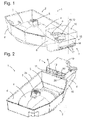
- Fig. 1 and 2 show an evaporation shell assembly 1 according to the invention in perspective views.
- An approximately rectangular in plan view evaporation tray 2 of the evaporation tray assembly 1 has a bottom 3, in which a central bulge 4 is formed.
- the bulge 4 is shaped to fit tightly to the Top of a (in Fig. 1 not shown) compressor, on which the evaporation tray 2 is placed and to which it is anchored with the aid of formed at the top of the bulge 4 locking clips 5.
- the bottom 3 is surrounded by a circumferential, substantially vertical wall 6.
- a fan housing 7 On a narrow side of this wall 6, a fan housing 7 is arranged. It comprises two of the wall 6 at right angles immovably protruding triangular Fighter plates 8, which are connected at their upper edges to each other by a bottom plate 9.
- the bottom plate 9 is hidden in the assembled state under a cover 10.
- One corner of the lid 10 is in the FIGS. 1 to 3 broken away to give insight into a deflection space 11 between the lid 10 and the bottom plate 9; in Fig. 1 can be seen through the broken corner through an axial fan 12, which at the bottom of the bottom plate 9, below a large-scale central opening 13 (see Fig. 5 ) of the bottom plate 9 is mounted.
- An installation space 14 (see Fig. 5 ), which receives the axial fan 12 is limited by a lower housing part 15.
- a lower housing part 15 At one in the perspective of Fig. 1 the observer facing end wall 16 of the lower housing part 15 are parts of slots 17 can be seen, focusing on a in the Fig. 1 continue invisible oblique edge 18 and together form an intake opening for the axial fan 12.
- the outlet opening 19 is bounded at the bottom by a surge rib 20 whose upper edge is higher than an upper edge 24 of the evaporation shell 2 surrounding wall 6 and which serves to keep the water in the evaporation tray 2 from the axial fan 12, if it is due to a vibration of the refrigerator spilling over.
- Fig. 3 shows the evaporation tray assembly 1 in a partially unfolded configuration.
- the lower housing part 15 is opposite to in Fig. 1 and 2 shown configuration pivoted by 180 ° about an axis 21 which extends along a side facing away from the evaporation tray 2 edge of the bottom plate 9.
- the inclined edge 18 with the slots 17 extending thereon is now fully visible, and the Installation space 14 is open, so that parts of the suspended under the bottom plate 9, flat parallelepiped axial fan 12 can be seen below the viewer facing the fighter plate 8.
- Fig. 4 shows the evaporation tray assembly 1, again in a partially unfolded configuration, in a perspective view from below without the axial fan 12. Clearly visible is the bottom plate 9 with the opening 13 therein. On one of the fighter plates 8 a notch 40 is cut out. A slot 41 is placed in one of the side walls 36 so that it overlaps with the notch 40 in the folded position of the lower housing part and forms a passage for a supply cable of the axial fan 12. Brackets 42, in which the supply cable can be positively locked, are distributed along the wall 6 of the evaporation tray 2.
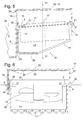
- Fig. 5 shows a section through the fan housing 7 along in Fig. 1 level designated IV-IV.
- the bottom plate 9 is slightly sloping down to the evaporation cup 2, which is only fragmentarily shown, at an angle of 5-10 °, so that air which is blown by the axial fan 12 in the direction of its axis 22 through the opening 13 of the bottom plate 9 is slightly less must be deflected at 90 ° in order to then sweep horizontally over the water level in the evaporation tray 2.
- the opening 13 may be surrounded by a second surge rib 23 as additional protection against splash water or against condensation, which may be reflected on the walls of the deflection space 11. Since the bottom plate 9 is over its entire extent above the upper edge 24 of the wall 6, it is possible to deduce condensation from the bottom plate 9 in the evaporation tray 2.
- the surge rib 20 may be provided with a narrow passage in the form of a bore or a slot. Although such a narrow passage does not allow appreciable amount of it to pass through during the short time that surge water may be present on the outside of the surge fin 20; However, drops of condensation, which may come from the bottom plate 9 coming forth the surge rib 20 and constantly abut the passage, but this can happen.
- a flat top 25 of the lid 10 is here as the bottom plate 9, albeit at a smaller angle than this, down to the evaporation tray 2 down to condensation, which may be reflected in a rest phase of the axial fan 12 under the lid 10, for draining into Direction of the outlet opening 19 to cause.
- a downwardly directed Abtropfvorsprung 26 is formed at the outlet opening 19 limiting edge of the upper side 25 .
- the drip projection 26 may be in the form of a continuous solid edge, or it may be as shown in FIG Fig. 6 shown to be divided into a plurality of spaced apart along the edge Abtropfnasen. The lowest point of the drip projection 26 should in any case be beyond the surge rib 20, on the side of the evaporation tray 2, so that falling from the projection 26 drops are not prevented by the surge rib 20 from reaching the evaporation tray 2.
- axis 21 about which the lower housing part 15 is pivotable is formed by a film hinge 27 which connects the edge of the bottom plate 9 facing away from the evaporation tray 2 with the end wall 16.
- the lower housing part 15 is secured by latching, for example, as shown here, in which a bottom plate 28 of the housing part 15 engages behind the wall 6 projecting locking lugs 29 and is supported on this.
- Fig. 6 shows a section through the fan housing 7 along in Fig. 5 Level named VI-VI. It can be seen the flat top 25 and two side walls 30, 31 of the lid 10. Between a lower edge of the side wall 31 and one of the fighter plates 8, another film hinge 32 is formed, which supports a 180 ° pivoting movement of the lid 10. In the in Fig. 6 shown closed position, the lid 10 is latched to the bottom plate 9, in the case shown here by means of a latching tongue 33 of the side wall 30, which, as shown, engages in a recess 34 of the adjacent fighter plate 8 or engages around the lower edge.
- the locking tongue 33 passes through a passage 35 of the bottom plate 9 to extend below this in a narrow space between the fighter plate 8 and a side wall 36 of the lower housing part 15.
- the space is so narrow that the latching tongue 33, the recess 34 can not leave.
- the evaporation tray assembly 1 is injection molded from plastic in one piece in a configuration in which both the lid 10 and the lower housing part 15 in the in Fig. 3 are unfolded for the lower housing part 15 shown manner.
- the lid 10 in the position of Fig. 6 folded and fixed by engagement of the latching tongue 33 in the recess 34.
- the axial fan 12 is mounted under the bottom plate 9.
- the installation space 14 around the axial fan 12 is closed by pivoting the lower housing part 15.
- the freedom of movement of the latching tongue 33 is restricted by the side wall 36 so that latching tongue 33, the recess 34 can not leave, that is, the lid 10 is locked.
- Fig. 7 shows a schematic view of a recessed on the back of a household refrigerator engine room 37.
- the evaporation tray assembly 1 is mounted on a compressor 38 here.
- the axial fan 12 accommodated in the fan housing 7 drives an air flow illustrated by arrows, which flows via a condenser 39 to the fan housing 7 and from there sweeps horizontally across the evaporation tray 2. If compressors 38 are used with different heights, although the position of the evaporation tray assembly 1 in the machine room 37, but not the air flow relative to the water level changes in the evaporation tray 2. Therefore, a constant effectiveness of the evaporation is guaranteed regardless of the model of the compressor 38.
- the fan housing 7 is located at a central location of the machine room 37, far away from all walls.
- the anchored to the brackets 42 of the evaporation tray 2 supply cable 43 connects the hidden in the fan housing 7 axial fan 12 with an arranged on a side wall of the engine room 37 electrical distributor.
- Fig. 8 shows an evaporative shell assembly 1 according to a second embodiment of the invention in a perspective view.
- An evaporation tray 2 is as in the case of Fig. 1 in plan view substantially rectangular with four walls 6a, 6b, 6c, 6d, one of which, 6d, in Fig. 8 is not visible.
- a bottom 3 of the evaporation tray 2 has a central bulge 4, which is provided to a compressor in close contact to be put over.
- From the wall 6d of the evaporation tray 2 is an in Fig. 8 not visible plate 45 to the outside (s. Fig. 9 ).
- the plate 45 may be down to the center of the shell 2, so that it is washed over at high water level in the evaporation tray 2 and the water level at which evaporation can take place increased.
- the fan housing 7 which is injection-molded in one piece from plastic, comprises a fan receptacle 46 and a ceiling plate 48.
- the fan receptacle 46 is shaped as a flat block-shaped box open at the bottom and provided with suction slots 47 at its upper side Fig. 9 shown covers a large part of the plate 45 and extends to a small part over the bottom 3 of the evaporation tray 2, and in which an axial fan 12 is mounted with a vertically oriented axis of rotation.
- the ceiling plate 48 extends over the entire depth of the evaporation tray 2, from the wall 6a to the wall 6c. On its underside air guide ribs 49 are formed, whose downstream ends in Fig. 8 are visible. In the embodiment considered here, the air guide ribs 49 are arranged on a strip of the ceiling plate 48, which extends between the fan receptacle 46 and a downstream edge 50 of the ceiling plate 48 from the side wall 6a to the side wall 6c, and extend parallel to each other and in the same length perpendicular to the edge 50.
- the air guide ribs 49 distribute the driven by the fan 12 and deflected in a gap 51 between the fan 12 and the plate 45 and the water level 52 of the evaporation tray 2 in the horizontal air flow evenly over the depth of the evaporation tray 2 and direct him, parallel to the walls 6a, 6c of the evaporation tray 2 are aligned, laminar over the water level 52.
- a water level sensor can be provided on the evaporation tray 2.
Landscapes
- Engineering & Computer Science (AREA)
- Chemical & Material Sciences (AREA)
- Combustion & Propulsion (AREA)
- Physics & Mathematics (AREA)
- Mechanical Engineering (AREA)
- Thermal Sciences (AREA)
- General Engineering & Computer Science (AREA)
- Removal Of Water From Condensation And Defrosting (AREA)
Abstract
Description
- Die vorliegende Erfindung betrifft ein Kältegerät, insbesondere ein Haushaltskältegerät, sowie eine in einem solchen Kältegerät verwendbare Verdunstungsschalenbaugruppe.
- Haushaltskältegeräte wie etwa Kühlschränke oder selbst abtauende Gefriergeräte weisen im Allgemeinen in einem Maschinenraum eine Verdunstungsschale auf, der Kondenswasser, das sich an einem Verdampfer des Kältegeräts niederschlägt, zugeführt wird, um darin verdunstet zu werden, üblicherweise unter Ausnutzung von Abwärme eines Verdichters, auf dem die Verdunstungsschale montiert ist.
- In modernen, energieeffizienten Kältegeräten ist die Menge der vom Verdichter freigesetzten Abwärme gering, so dass es nötig sein kann, die Verdunstung mithilfe eines Lüfters zu unterstützen, der einen über der Verdunstungsschale herstreichenden Luftstrom antreibt. Herkömmlicherweise ist ein solcher Lüfter an einer Begrenzungsfläche des Maschinenraums mit Hilfe eines Adapters befestigt. Wenn unterschiedliche Modelle von Verdichtern, insbesondere solche mit unterschiedlichen Bauhöhen, verbaut werden, ist auch die Position der auf dem Verdichter angeordneten Verdunstungsschale variabel. Wenn dies nicht zu Beeinträchtigungen bei der Durchlüftung des Maschinenraums führen soll, dann müssen unterschiedliche Typen von Adaptern verbaut werden, um den Lüfter jeweils passend zur Einbaulage der Verdunstungsschale so montieren zu können, dass er eine optimale Durchströmung des Maschinenraums gewährleistet. Der damit verbundene erhöhte Aufwand bei Logistik und Montage kann die wirtschaftlichen Vorteile der Verwendung unterschiedlicher Verdichtermodelle zunichte machen.
- Aufgabe der vorliegenden Erfindung ist, Mittel zu schaffen, die eine effiziente Verdunstung auch dann gewährleisten, wenn Verdichter mit unterschiedlichen Bauhöhen zum Einsatz kommen.
- Die Aufgabe wird zum einen gelöst durch eine Verdunstungsschalen-Baugruppe für ein Kältegerät, die eine Verdunstungsschale und eine an der Verdunstungsschale befestigte Lüfterhalterung umfasst. Eine solche Baugruppe erlaubt es, den Lüfter in einer zum Erzeugen eines die Verdunstungsschale überstreichenden Luftstroms günstigen Position zu montieren, unabhängig davon, welche Einbaulage der Verdunstungsschale innerhalb des Maschinenraums aus den Gehäusemaßen des jeweils verwendeten Verdichters resultiert.
- Vorzugsweise ist die Lüfterhalterung einteilig mit der Verdunstungsschale geformt. Insbesondere können beide zusammen aus Kunststoff spritzgeformt sein.
- Es kann aber auch zweckmäßig sein, Lüfterhalterung und Verdunstungsschale getrennt zu fertigen und aneinander zu verrasten, insbesondere wenn die Verdunstungsschale keine hinreichend lange gerade Kante hat, die für die Realisierung eines Verdunstungsschale und Lüfterhalterung verbindenden Folienscharniers geeignet ist.
- Die Lüfterhalterung kann als ein den Lüfter aufnehmendes Gehäuse oder als Teil eines den Lüfter aufnehmenden Gehäuses ausgebildet sein.
- Ein solches Gehäuse kann ferner dazu dienen, den vom Lüfter erzeugten Luftstrom in Richtung der Verdunstungsschale umzulenken.
- Eine der Verdunstungsschale zugewandte Austrittsöffnung des Gehäuses kann durch eine Schwallrippe begrenzt sein, deren Oberkante höher liegt als eine Oberkante der Verdunstungsschale. Eine solche Schwallrippe kann den Lüfter vor Wasser schützen, falls ein Kältegerät, in dem die Verdunstungsschale in Baugruppe verbaut ist, bewegt wird, während die Verdunstungsschale Wasser enthält.
- Das Gehäuse kann ausgelegt sein, um einen Axiallüfter platzsparend mit im Wesentlichen vertikaler Drehachse aufzunehmen. Dabei sind sowohl Ausgestaltungen denkbar, bei denen der Lüfter seitlich gegen die Verdunstungsschale versetzt ist und ganz oder teilweise unterhalb des Wasserspiegels der Verdunstungsschale Platz findet, als auch solche, bei denen er in Draufsicht ganz oder teilweise mit der Verdunstungsschale überlappt. In letzterem Fall sollte er über dem Wasserspiegel angeordnet sein.
- Wenn die Drehachse des Axiallüfters vertikal orientiert ist,ist zweckmäßigerweise zwischen einem Einbauraum des Axiallüfters und einer Luftaustrittsöffnung des Gehäuses ein Umlenkraum vorgesehen, um den vom Axiallüfter angetriebenen Luftstrom in die Horizontale umzulenken.
- Je nach Anordnung des Lüfters, seitlich versetzt oder oberhalb der Verdunstungsschale, kann auch der Umlenkraum seitlich gegen die Verdunstungsschale versetzt oder vom Wasserspiegel der Verdunstungsschale begrenzt sein.
Eine Deckenplatte des Gehäuses kann sich über die Verdunstungsschale erstrecken, um den vom Lüfter angetriebenen Luftstrom dicht über dem Wasserspiegel zu führen und so eine effiziente Ableitung von Wasserdampf zu gewährleisten. - Um Turbulenz zu vermeiden und eine gleichmäßige Überspülung der Wasseroberfläche zu gewährleisten, kann die Deckenplatte mit der Verdunstungsschale zugewandten Luftführungsrippen versehen sein.
- Die Überdeckung der Verdunstungsschale durch die Deckenplatte sollte unvollständig sein, damit in einem nicht von der Deckenplatte überdeckten Bereich der Wasseroberfläche, vorzugsweise an einer stromabwärtigen Seite der Deckenplatte, eine ungehinderte Verdunstung möglich bleibt, auch wenn der Lüfter nicht in Betrieb ist.
- Insbesondere bei seitlich versetzter Anordnung kann der Umlenkraum von einer Bodenplatte, an der der Axiallüfter befestigt ist, und einem auf die Bodenplatte aufgesetzten Deckel begrenzt sein.
- Die Bodenplatte kann zur Verdunstungsschale hin abschüssig sein, um den Winkel, um den der Luftstrom in dem Umlenkraum umgelenkt wird, klein zu machen und Effizienzverluste des Lüfters aufgrund der Umlenkung zu minimieren.
- Die Neigung der Bodenplatte sollte kleiner als 15° sein; vorzugsweise beträgt sie zwischen 5° und 10°.
- Der Deckel kann an einem der Verdunstungsschale zugewandten Rand eine Tropfnase aufweisen, um sicherzustellen, dass an einer Innenseite des Deckels kondensierende Feuchtigkeit auf Seiten der Verdunstungsschale, insbesondere an der der Verdunstungsschale zugewandten Seite der Schwallrippe, abtropft und nicht den Lüfter erreicht.
- Der Deckel ist vorzugsweise mit der Bodenplatte über ein Scharnier, insbesondere ein Folienscharnier, verbunden. Dies ermöglicht eine Fertigung von Deckel und Bodenplatte mit einem einzigen, einfach aufgebauten Formwerkzeug.
- Aufgrund der Umlenkung des Luftstroms ist es möglich, den Lüfter platzsparend unterhalb einer Oberkante der Verdunstungsschale anzuordnen.
- Um den Einbau des Lüfters zu vereinfachen, ist der Einbauraum vorzugsweise von einem an der Verdunstungsschale festen Gehäuseteil und einem bezüglich dieses festen Gehäuseteils bewegbaren Gehäuseteil begrenzt.
- Auch dieser bewegbare Teil ist vorzugsweise über ein Scharnier, insbesondere ein Folienscharnier, an den festen Gehäuseteil angelenkt.
- Eine Durchführung für ein Versorgungskabel des Lüfters kann durch überlappende Kerben und/oder Schlitze des festen und des bewegbaren Gehäuseteils gebildet sein.
- An der Verdunstungsschale können Klammern für eine formschlüssige Verankerung des Versorgungskabels verteilt sein.
- Eine in dem bewegbaren Gehäuseteil gebildete Ansaugöffnung ist vorzugsweise mehrfach, insbesondere gitterartig unterteilt, um eine versehentliche Berührung des dahinter angeordneten rotierenden Lüfters zu verhindern.
- Die Ansaugöffnung befindet sich vorzugsweise an einer von der Verdunstungsschale abgewandten Seite des Gehäuses, um einen Kurzschlussstrom, bei dem an der Luftaustrittsöffnung ausgestoßene Luft zurück zur Ansaugöffnung fließt und erneut angesaugt wird, zu minimieren.
- Die Aufgabe wird ferner gelöst durch ein Kältegerät, bei dem eine Verdunstungsschalenbaugruppe des oben beschriebenen Typs auf einem Verdichter montiert ist.
- Weitere Merkmale und Vorteile der Erfindung ergeben sich aus der nachfolgenden Beschreibung von Ausführungsbeispielen unter Bezugnahme auf die beigefügten Figuren. Es zeigen:
- Fig. 1
- eine perspektivische Ansicht einer Verdunstungsschalenbaugruppe mit darin montiertem Lüfter gemäß einer ersten Ausgestaltung der Erfindung;
- Fig. 2
- eine zweite perspektivische Ansicht der Verdunstungsschalenbaugruppe;
- Fig. 3
- eine dritte perspektivische Ansicht der Verdunstungsschalenbaugruppe mit teilweise aufgeklapptem Gehäuse;
- Fig. 4
- die Verdunstungsschalenbaugruppe in einer perspektivischen Ansicht von unten;
- Fig. 5
- einen schematischen Schnitt durch ein Lüftergehäuse der Verdunstungsschalenbaugruppe;
- Fig. 6
- einen Schnitt entlang der Ebene VI-VI aus
Fig. 5 ; - Fig. 7
- eine schematische Rückansicht des unteren Teils eines Kältegeräts, in dem die Verdunstungsschalenbaugruppe gemäß der ersten Ausgestaltung verbaut ist;
- Fig. 8
- eine perspektivische Ansicht einer Verdunstungsschalenbaugruppe gemäß einer zweiten Ausgestaltung der Erfindung; und
- Fig. 9
- einen partiellen Schnitt durch die Verdunstungsschalenbaugruppe der
Fig. 8 . -
Fig. 1 und 2 zeigen eine erfindungsgemäße Verdunstungsschalenbaugruppe 1 in perspektivischen Ansichten. Eine in Draufsicht angenähert rechteckige Verdunstungsschale 2 der Verdunstungsschalenbaugruppe 1 hat einen Boden 3, in dem eine zentrale Aufwölbung 4 gebildet ist. Die Aufwölbung 4 ist geformt, um sich eng an die Oberseite eines (inFig. 1 nicht dargestellten) Verdichters anzuschmiegen, auf den die Verdunstungsschale 2 aufgesetzt wird und an dem sie mit Hilfe von an der Spitze der Aufwölbung 4 gebildeten Rastklammern 5 verankert ist. Der Boden 3 ist umgeben von einer umlaufenden, im Wesentlichen vertikalen Wand 6. - An einer schmalseitigen Flanke dieser Wand 6 ist ein Lüftergehäuse 7 angeordnet. Es umfasst zwei von der Wand 6 im rechten Winkel unbeweglich abstehende dreieckige Kämpferplatten 8, die an ihren Oberkanten untereinander durch eine Bodenplatte 9 verbunden sind. Die Bodenplatte 9 ist in fertig montiertem Zustand unter einem Deckel 10 verborgen. Eine Ecke des Deckels 10 ist in den
Figuren 1 bis 3 weggebrochen, um Einblick in einen Umlenkraum 11 zwischen dem Deckel 10 und der Bodenplatte 9 zu geben; inFig. 1 sieht man durch die weggebrochene Ecke hindurch einen Axiallüfter 12, der an der Unterseite der Bodenplatte 9, unterhalb einer großflächigen zentralen Öffnung 13 (sieheFig. 5 ) der Bodenplatte 9 montiert ist. - Ein Einbauraum 14 (siehe
Fig. 5 ), der den Axiallüfter 12 aufnimmt, ist von einem unteren Gehäuseteil 15 begrenzt. An einer in der Perspektive derFig. 1 dem Betrachter zugewandten Stirnwand 16 des unteren Gehäuseteils 15 sind Teile von Schlitzen 17 zu erkennen, die sich auf eine in derFig. 1 nicht sichtbare schräge Flanke 18 fortsetzen und zusammen eine Ansaugöffnung für den Axiallüfter 12 bilden. - Wie in
Fig. 2 zu erkennen, hat der Umlenkraum 11, in den der Axiallüfter 12 die über die Ansaugöffnung aufgenommene Luft einbläst, eine Austrittsöffnung 19 an seiner der Verdunstungsschale 2 zugewandten Seite. Die Austrittsöffnung 19 ist nach unten begrenzt durch eine Schwallrippe 20, deren Oberkante höher liegt als eine Oberkante 24 der die Verdunstungsschale 2 umgebenden Wand 6 und die dazu dient, das Wasser in der Verdunstungsschale 2 vom Axiallüfter 12 fernzuhalten, falls es aufgrund einer Erschütterung des Kältegeräts überschwappt. -
Fig. 3 zeigt die Verdunstungsschalenbaugruppe 1 in einer teilweise aufgeklappten Konfiguration. Das untere Gehäuseteil 15 ist gegenüber der inFig. 1 und 2 gezeigten Konfiguration um 180° um eine Achse 21 geschwenkt, die sich entlang einer von der Verdunstungsschale 2 abgewandten Kante der Bodenplatte 9 erstreckt. Die schräge Flanke 18 mit den sich daran erstreckenden Schlitzen 17 ist nun voll sichtbar, und der Einbauraum 14 liegt offen, so dass Teile des unter der Bodenplatte 9 aufgehängten, flach quaderförmigen Axiallüfters 12 unterhalb der dem Betrachter zugewandten Kämpferplatte 8 zu erkennen sind. -
Fig. 4 zeigt die Verdunstungsschalenbaugruppe 1, wiederum in teilweise aufgeklappter Konfiguration, in einer perspektivischen Ansicht von unten ohne den Axiallüfter 12. Deutlich zu erkennen ist die Bodenplatte 9 mit der Öffnung 13 darin. An einer der Kämpferplatten 8 ist eine Kerbe 40 ausgeschnitten. Ein Schlitz 41 ist in einer der Seitenwände 36 so platziert, dass er in der zugeklappten Stellung des unteren Gehäuseteils mit der Kerbe 40 überlappt und einen Durchgang für ein Versorgungskabel des Axiallüfters 12 bildet. Klammern 42, in denen das Versorgungskabel formschlüssig verrastbar ist, sind entlang der Wand 6 der Verdunstungsschale 2 verteilt. -
Fig. 5 zeigt einen Schnitt durch das Lüftergehäuse 7 entlang der inFig. 1 mit IV-IV bezeichneten Ebene. Die Bodenplatte 9 ist zur hier nur bruchstückhaft gezeigten Verdunstungsschale 2 hin unter einem Winkel von 5-10° leicht abschüssig, so dass Luft, die vom Axiallüfter 12 in Richtung von dessen Achse 22 durch die Öffnung 13 der Bodenplatte 9 geblasen wird, um etwas weniger als 90° abgelenkt werden muss, um anschließend horizontal über den Wasserspiegel in der Verdunstungsschale 2 zu streichen. - Die Öffnung 13 kann als zusätzlicher Schutz vor Schwallwasser oder vor Kondenswasser, das sich möglicherweise an den Wänden des Umlenkraums 11 niederschlägt, von einer zweiten Schwallrippe 23 umgeben sein. Da die Bodenplatte 9 auf ihrer gesamten Ausdehnung über der Oberkante 24 der Wand 6 liegt, ist es möglich, Kondenswasser von der Bodenplatte 9 in die Verdunstungsschale 2 abzugeleiten. Zu diesem Zweck kann beispielsweise die Schwallrippe 20 mit einem engen Durchgang in Form einer Bohrung oder eines Schlitzes versehen sein. Ein solcher enger Durchgang lässt zwar während der kurzen Zeit, in der möglicherweise Schwallwasser an der Außenseite der Schwallrippe 20 ansteht, keine nennenswerte Menge davon durch; Tropfen von Kondenswasser, die eventuell von der Bodenplatte 9 her kommend die Schwallrippe 20 erreichen und dauernd am Durchgang anliegen, können diesen jedoch passieren.
- Eine ebene Oberseite 25 des Deckels 10 ist hier wie die Bodenplatte 9, wenn auch unter einem kleineren Winkel als diese, zur Verdunstungsschale 2 hin abschüssig, um Kondenswasser, das sich in einer Ruhephase des Axiallüfters 12 möglicherweise unter dem Deckel 10 niederschlägt, zum Abfließen in Richtung der Austrittsöffnung 19 zu veranlassen. An dem die Austrittsöffnung 19 begrenzenden Rand der Oberseite 25 ist ein abwärts gerichteter Abtropfvorsprung 26 gebildet. Der Abtropfvorsprung 26 kann die Form einer kontinuierlich durchgezogenen Kante haben, oder er kann, wie in
Fig. 6 gezeigt, in mehrere voneinander entlang des Randes beabstandete Abtropfnasen untergliedert sein. Der tiefste Punkt des Abtropfvorsprungs 26 sollte in jedem Falle jenseits der Schwallrippe 20, auf Seiten der Verdunstungsschale 2, liegen, so dass von dem Vorsprung 26 abfallende Tropfen nicht von der Schwallrippe 20 daran gehindert werden, die Verdunstungsschale 2 zu erreichen. - In
Fig. 5 ist ferner zu erkennen, dass die Achse 21, um die das untere Gehäuseteil 15 schwenkbar ist, durch ein Folienscharnier 27 gebildet ist, das die von der Verdunstungsschale 2 abgewandte Kante der Bodenplatte 9 mit der Stirnwand 16 verbindet. In der inFig. 5 gezeigten geschlossenen Stellung ist das untere Gehäuseteil 15 durch Verrastung gesichert, zum Beispiel, wie hier gezeigt, in dem eine Bodenplatte 28 des Gehäuseteils 15 hinter von der Wand 6 abstehende Rastnasen 29 eingreift und auf diesen abgestützt ist. -
Fig. 6 zeigt einen Schnitt durch das Lüftergehäuse 7 entlang der inFig. 5 mit VI-VI bezeichneten Ebene. Man erkennt die flache Oberseite 25 sowie zwei Seitenwände 30, 31 des Deckels 10. Zwischen einer Unterkante der Seitenwand 31 und einer der Kämpferplatten 8 ist ein weiteres Folienscharnier 32 gebildet, das eine 180°-Schwenkbewegung auch des Deckels 10 unterstützt. In der inFig. 6 gezeigten geschlossenen Stellung ist der Deckel 10 an der Bodenplatte 9 verrastet, im hier gezeigten Fall mit Hilfe einer Rastzunge 33 der Seitenwand 30, die, wie gezeigt, in eine Aussparung 34 der benachbarten Kämpferplatte 8 eingreift oder deren Unterkante umgreift. Im hier gezeigten Fall durchsetzt die Rastzunge 33 einen Durchgang 35 der Bodenplatte 9, um sich unterhalb von dieser in einem engen Zwischenraum zwischen der Kämpferplatte 8 und einer Seitenwand 36 des unteren Gehäuseteils 15 zu erstrecken. Der Zwischenraum ist so eng, dass die Rastzunge 33 die Aussparung 34 nicht verlassen kann. - Die Verdunstungsschalenbaugruppe 1 wird aus Kunststoff einteilig in einer Konfiguration spritzgeformt, in der sowohl der Deckel 10 als auch der untere Gehäuseteil 15 in der in
Fig. 3 für den unteren Gehäuseteil 15 gezeigten Weise ausgeklappt sind. Ausgehend von dieser Konfiguration wird zunächst der Deckel 10 in die Stellung derFig. 6 geklappt und durch Eingriff der Rastzunge 33 in der Aussparung 34 fixiert. Vor oder nach Zuklappen des Deckels 10 wird der Axiallüfter 12 unter der Bodenplatte 9 montiert. Nach Schließen des Deckels 10 wird durch Schwenken des unteren Gehäuseteils 15 der Einbauraum 14 um den Axiallüfter 12 herum geschlossen. Dabei wird durch die Seitenwand 36 die Bewegungsfreiheit der Rastzunge 33 so eingeengt, dass Rastzunge 33 die Aussparung 34 nicht mehr verlassen kann, d.h. der Deckel 10 wird verriegelt. -
Fig. 7 zeigt eine schematische Ansicht eines an der Rückseite eines Haushaltskältegeräts ausgesparten Maschinenraums 37. Die Verdunstungsschalenbaugruppe 1 ist hier auf einem Verdichter 38 montiert. Der in dem Lüftergehäuse 7 geschützt untergebrachte Axiallüfter 12 treibt einen durch Pfeile veranschaulichten Luftstrom an, der über einen Verflüssiger 39 zum Lüftergehäuse 7 verläuft und von dort aus horizontal über die Verdunstungsschale 2 streicht. Falls Verdichter 38 mit unterschiedlichen Bauhöhen verwendet werden, ändert sich zwar die Lage der Verdunstungsschalenbaugruppe 1 im Maschinenraum 37, nicht aber die des Luftstroms relativ zum Wasserspiegel in der Verdunstungsschale 2. Daher ist eine gleichbleibende Effektivität der Verdunstung unabhängig vom Modell des Verdichters 38 gewährleistet. - Das Lüftergehäuse 7 befindet sich an zentraler Stelle des Maschinenraums 37, weit entfernt von allen Wänden. Das an den Klammern 42 der Verdunstungsschale 2 verankerte Versorgungskabel 43 verbindet den im Lüftergehäuse 7 verborgenen Axiallüfter 12 mit einem an einer Seitenwand des Maschinenraums 37 angeordneten elektrischen Verteiler.
-
Fig. 8 zeigt eine Verdunstungsschalenbaugruppe 1 gemäß einer zweiten Ausgestaltung der Erfindung in perspektivischer Ansicht. Eine Verdunstungsschale 2 ist wie im Falle derFig. 1 in Draufsicht im Wesentlichen rechteckig mit vier Wänden 6a, 6b, 6c, 6d, von denen eine, 6d, inFig. 8 nicht sichtbar ist. Ein Boden 3 der Verdunstungsschale 2 weist eine zentrale Aufwölbung 4 auf, die vorgesehen ist, um einem Verdichter in engem Kontakt übergestülpt zu werden. Von der Wand 6d der Verdunstungsschale 2 steht eine inFig. 8 nicht sichtbare Platte 45 nach außen ab (s.Fig. 9 ). Die Platte 45 kann zur Mitte der Schale 2 hin abschüssig sein, so dass sie bei hohem Wasserstand in der Verdunstungschale 2 überspült wird und den Wasserspiegel, an dem Verdunstung stattfinden kann, vergrößert. - An den äußeren Rand der Platte 45, die Wand 6d und Teile der daran angrenzenden Wände 6a, 6c ist ein Lüftergehäuse 7 aufgerastet. Das aus Kunststoff einteilig spritzgeformte Lüftergehäuse 7 umfasst eine Lüfteraufnahme 46 sowie eine Deckenplatte 48. Die Lüfteraufnahme 46 ist als ein flach quaderförmiger, nach unten offener und an seiner Oberseite mit Ansaugschlitzen 47 versehener Kasten geformt, der wie in
Fig. 9 gezeigt einen großen Teil der Platte 45 überdeckt und sich zu einen kleinen Teil über den Boden 3 der Verdunstungsschale 2 erstreckt, und in dem ein Axiallüfter 12 mit vertikal orientierter Drehachse montierbar ist. - Die Deckenplatte 48 erstreckt sich über die gesamte Tiefe der Verdunstungsschale 2, von der Wand 6a bis zur Wand 6c. An ihrer Unterseite sind Luftführungsrippen 49 geformt, deren stromabwärtige Enden in
Fig. 8 sichtbar sind. Bei der hier betrachteten Ausgestaltung sind die Luftführungsrippen 49 an einem Streifen der Deckenplatte 48 angeordnet, der sich zwischen der Lüfteraufnahme 46 und einer stromabwärtigen Kante 50 der Deckenplatte 48 von der Seitenwand 6a zur Seitenwand 6c erstreckt, und verlaufen parallel zueinander und in gleicher Länge senkrecht zu der Kante 50. - Die Luftführungsrippen 49 verteilen den vom Lüfter 12 angetriebenen und in einem Zwischenraum 51 zwischen dem Lüfter 12 und der Platte 45 bzw. dem Wasserspiegel 52 der Verdunstungsschale 2 in die Horizontale umgelenkten Luftstrom gleichmäßig über die Tiefe der Verdunstungsschale 2 und lenken ihn, parallel zu den Wänden 6a, 6c der Verdunstungsschale 2 ausgerichtet, laminar über den Wasserspiegel 52. Indem sie so für eine gleichmäßige Strömungsgeschwindigkeit der Luft über der gesamten Wasseroberfläche sorgen, ermöglichen sie eine effiziente Abführung des Wasserdampfs von der Verdunstungsschale 2, einschließlich des nicht von dem Lüftergehäuse 7 überdeckten Teils des Wasserspiegels 52, und folglich eine zügige Verdunstung.
- Wie anhand von
Fig. 8 deutlich wird, ist der nicht vom Lüftergehäuse 7 überdeckte Teil des Wasserspiegels 52 (bzw. des Bodens 3) deutlich größer als der überdeckte. In dem nicht überdeckten Bereich der Verdunstungsschale 2 kann Luft, die sich an der Wasseroberfläche erwärmt, frei aufsteigen und dabei den in ihr enthaltenen Wasserdampf mitnehmen. So ist ein effizienter Abtransport des Wasserdampfs auch bei ausgeschaltetem Lüfter 12 möglich. Wenn das Kältegerät in einer kühlen Umgebung eingesetzt wird, in der der Anfall an Tauwasser gering ist, kann eine ausreichende Verdunstung daher auch ohne Betrieb des Lüfters 12 erreicht werden. - Um den Lüfter 12 bei Bedarf zuzuschalten, kann ein Wasserstandssensor an der Verdunstungsschale 2 vorgesehen sein.
- Insbesondere bei Geräten, die für den Einsatz in einer Umgebung mit starkem Tauwasseranfall, insbesondere in tropischen Ländern, vorgesehen sind, kann in der Verdunstungsschale zusätzlich noch eine Heizung vorgesehen sein. Um den Wirkungsgrad des Geräts nicht unnötig zu beeinträchtigen, sollte eine solche Heizung allerdings nur bei hohem Wasserstand in der Verdunstungsschale in Betrieb gehen.
-
- 1
- Verdunstungsschalenbaugruppe
- 2
- Verdunstungsschale
- 3
- Boden
- 4
- Aufwölbung
- 5
- Rastklammer
- 6
- Wand
- 7
- Lüftergehäuse
- 8
- Kämpferplatte
- 9
- Bodenplatte
- 10
- Deckel
- 11
- Umlenkraum
- 12
- Axiallüfter
- 13
- Öffnung
- 14
- Einbauraum
- 15
- unterer Gehäuseteil
- 16
- Stirnwand
- 17
- Schlitz
- 18
- schräge Flanke
- 19
- Austrittsöffnung
- 20
- Schwallrippe
- 21
- Achse
- 22
- Achse
- 23
- Schwallrippe
- 24
- Oberkante
- 25
- Oberseite
- 26
- Abtropfvorsprung
- 27
- Folienscharnier
- 28
- Bodenplatte
- 29
- Rastnase
- 30
- Seitenwand
- 31
- Seitenwand
- 32
- Folienscharnier
- 33
- Rastzunge
- 34
- Aussparung
- 35
- Durchgang
- 36
- Seitenwand
- 37
- Maschinenraum
- 38
- Verdichter
- 39
- Verflüssiger
- 40
- Kerbe
- 41
- Schlitz
- 42
- Klammer
- 43
- Versorgungskabel
- 44
- Verteiler
- 45
- Platte
- 46
- Lüfteraufnahme
- 47
- Ansaugschlitz
- 48
- Deckenplatte
- 49
- Luftführungsrippe
- 50
- Stromabwärtige Kante
- 51
- Zwischenraum
Claims (15)
- Verdunstungsschalenbaugruppe (1) für ein Kältegerät mit einer Verdunstungsschale (2) und einer an der Verdunstungsschale (2) befestigten Lüfterhalterung.
- Verdunstungsschalenbaugruppe nach Anspruch 1, dadurch gekennzeichnet, dass die Lüfterhalterung einteilig mit der Verdunstungsschale (2) geformt, insbesondere aus Kunststoff spritzgeformt, ist.
- Verdunstungsschalenbaugruppe nach Anspruch 1, dadurch gekennzeichnet, dass die Lüfterhalterung an der Verdunstungsschale (2) verrastet ist.
- Verdunstungsschalenbaugruppe nach Anspruch 1, 2 oder 3, dadurch gekennzeichnet, dass die Lüfterhalterung als einen Lüfter (12) aufnehmendes Gehäuse (7) oder als Teil eines den Lüfter (12) aufnehmenden Gehäuses ausgebildet ist.
- Verdunstungsschalenbaugruppe nach Anspruch 4, dadurch gekennzeichnet, dass eine der Verdunstungsschale (2) zugewandte Luftaustrittsöffnung (19) des Gehäuses (7) durch eine Schwallrippe (20) begrenzt ist, deren Oberkante höher liegt als eine Oberkante (24) der Verdunstungsschale (2).
- Verdunstungsschalenbaugruppe nach Anspruch 4 oder 5, dadurch gekennzeichnet, dass das Gehäuse (7) ausgelegt ist, um einen Axiallüfter (12) mit im Wesentlichen vertikaler Drehachse (22) aufzunehmen.
- Verdunstungsschalenbaugruppe nach Anspruch 3, dadurch gekennzeichnet, dass eine Deckenplatte (48) des Gehäuses (7) sich über die Verdunstungsschale (2) erstreckt.
- Verdunstungsschalenbaugruppe nach Anspruch 7, dadurch gekennzeichnet, dass die Deckenplatte (48) der Verdunstungsschale (2) zugewandte Luftführungsrippen (49) trägt.
- Verdunstungsschalenbaugruppe nach Anspruch 7 oder 8, dadurch gekennzeichnet, dass die Verdunstungsschale (2) von der Deckenplatte (48) unvollständig überdeckt ist.
- Verdunstungsschalenbaugruppe nach einem der Ansprüche 7 bis 9, dadurch gekennzeichnet, dass der Lüfter (12) mit der Verdunstungsschale (2) in Draufsicht überlappt.
- Verdunstungsbaugruppe nach Anspruch 6, dadurch gekennzeichnet, dass das Gehäuse (7) zwischen einem Einbauraum (14) des Axiallüfters (12) und einer Luftaustrittsöffnung (19) einen Umlenkraum (11) zum Umlenken des von dem Axiallüfter (12) angetriebenen Luftstroms in die Horizontale aufweist.
- Verdunstungsschalenbaugruppe nach Anspruch 11, dadurch gekennzeichnet, dass der Umlenkraum (11) von einer Bodenplatte (9), an der der Axiallüfter (12) befestigt ist, und einem auf die Bodenplatte (9) aufgesetzten Deckel (10) begrenzt ist.
- Verdunstungsschalenbaugruppe nach Anspruch 12, dadurch gekennzeichnet, dass die Bodenplatte (9) zur Verdunstungsschale (2) hin abschüssig ist.
- Verdunstungsschalenbaugruppe nach einem der Ansprüche 12 bis 13, dadurch gekennzeichnet, dass der Deckel (10) mit der Bodenplatte (9) über ein Scharnier, insbesondere ein Folienscharnier (27), verbunden ist.
- Kältegerät, bei dem eine Verdunstungsschalenbaugruppe (1) nach einem der vorhergehenden Ansprüche auf einem Verdichter (38) montiert ist.
Priority Applications (1)
| Application Number | Priority Date | Filing Date | Title |
|---|---|---|---|
| PL15157194T PL2927627T3 (pl) | 2014-03-31 | 2015-03-02 | Urządzenie chłodnicze i zespół tac wyparnych do niego |
Applications Claiming Priority (2)
| Application Number | Priority Date | Filing Date | Title |
|---|---|---|---|
| DE102014206085 | 2014-03-31 | ||
| DE102014222258.3A DE102014222258A1 (de) | 2014-03-31 | 2014-10-31 | Kältegerät und Verdunstungsschalenbaugruppe dafür |
Publications (2)
| Publication Number | Publication Date |
|---|---|
| EP2927627A1 true EP2927627A1 (de) | 2015-10-07 |
| EP2927627B1 EP2927627B1 (de) | 2018-05-30 |
Family
ID=52598620
Family Applications (1)
| Application Number | Title | Priority Date | Filing Date |
|---|---|---|---|
| EP15157194.0A Active EP2927627B1 (de) | 2014-03-31 | 2015-03-02 | Kältegerät und verdunstungsschalenbaugruppe dafür |
Country Status (4)
| Country | Link |
|---|---|
| EP (1) | EP2927627B1 (de) |
| DE (1) | DE102014222258A1 (de) |
| PL (1) | PL2927627T3 (de) |
| TR (1) | TR201809768T4 (de) |
Cited By (1)
| Publication number | Priority date | Publication date | Assignee | Title |
|---|---|---|---|---|
| EP4414638A1 (de) | 2023-02-13 | 2024-08-14 | BSH Hausgeräte GmbH | Kältegerät und verdunstungseinrichtung für ein kältegerät |
Citations (5)
| Publication number | Priority date | Publication date | Assignee | Title |
|---|---|---|---|---|
| KR20010092062A (ko) * | 2000-03-20 | 2001-10-24 | 구자홍 | 냉장고의 기계실 팬가이드 장착구조 |
| JP2008002797A (ja) * | 2006-02-01 | 2008-01-10 | Matsushita Electric Ind Co Ltd | 冷蔵庫 |
| JP2009030864A (ja) * | 2007-07-26 | 2009-02-12 | Hitachi Appliances Inc | 冷蔵庫 |
| JP2010279550A (ja) * | 2009-06-04 | 2010-12-16 | Mitsubishi Electric Corp | 蒸発装置 |
| JP2011185472A (ja) * | 2010-03-05 | 2011-09-22 | Panasonic Corp | 冷蔵庫 |
-
2014
- 2014-10-31 DE DE102014222258.3A patent/DE102014222258A1/de not_active Withdrawn
-
2015
- 2015-03-02 EP EP15157194.0A patent/EP2927627B1/de active Active
- 2015-03-02 TR TR2018/09768T patent/TR201809768T4/tr unknown
- 2015-03-02 PL PL15157194T patent/PL2927627T3/pl unknown
Patent Citations (5)
| Publication number | Priority date | Publication date | Assignee | Title |
|---|---|---|---|---|
| KR20010092062A (ko) * | 2000-03-20 | 2001-10-24 | 구자홍 | 냉장고의 기계실 팬가이드 장착구조 |
| JP2008002797A (ja) * | 2006-02-01 | 2008-01-10 | Matsushita Electric Ind Co Ltd | 冷蔵庫 |
| JP2009030864A (ja) * | 2007-07-26 | 2009-02-12 | Hitachi Appliances Inc | 冷蔵庫 |
| JP2010279550A (ja) * | 2009-06-04 | 2010-12-16 | Mitsubishi Electric Corp | 蒸発装置 |
| JP2011185472A (ja) * | 2010-03-05 | 2011-09-22 | Panasonic Corp | 冷蔵庫 |
Cited By (2)
| Publication number | Priority date | Publication date | Assignee | Title |
|---|---|---|---|---|
| EP4414638A1 (de) | 2023-02-13 | 2024-08-14 | BSH Hausgeräte GmbH | Kältegerät und verdunstungseinrichtung für ein kältegerät |
| DE102023201153A1 (de) | 2023-02-13 | 2024-08-14 | BSH Hausgeräte GmbH | Kältegerät und Verdunstungseinrichtung für ein Kältegerät |
Also Published As
| Publication number | Publication date |
|---|---|
| EP2927627B1 (de) | 2018-05-30 |
| PL2927627T3 (pl) | 2018-10-31 |
| TR201809768T4 (tr) | 2018-07-23 |
| DE102014222258A1 (de) | 2015-10-01 |
Similar Documents
| Publication | Publication Date | Title |
|---|---|---|
| DE19609687C2 (de) | Wandkühlgerät für einen Schaltsschrank mit einem Lüfter und einem Lamellen-Wärmetauscher | |
| DE19734146C2 (de) | Luftzuführeinrichtung | |
| EP2678623B1 (de) | Kältegerät mit verdunstungsschale | |
| WO2004001306A1 (de) | Verdichter-verdunstungsschale-anordnung für ein kältegerät | |
| EP2697578B1 (de) | Kältegerät mit verdunstungsschale | |
| EP2160553A1 (de) | Kältegerät mit lüfteraggregat | |
| EP2927627B1 (de) | Kältegerät und verdunstungsschalenbaugruppe dafür | |
| DE102017213972A1 (de) | Kältegerät mit Verdunstungsschale | |
| DE102010013639A1 (de) | Kühlaggregat für Schaltschränke | |
| EP2492620A1 (de) | Kältegerät mit Verdichterkondensator | |
| WO2004083750A1 (de) | Kältegerät mit innenraumbeleuchtung und gebläse | |
| DE102005021560A1 (de) | Kältegerät mit Umluftkühlung | |
| EP2396612B1 (de) | Kältegerät mit innen liegendem verdampfer | |
| EP2618084B1 (de) | Ablagevorrichtung aufweisend eine Klappenbefestigungsvorrichtung und Haushaltskältegerät mit einer solchen Ablagevorrichtung | |
| EP2419687B1 (de) | No-frost-kältegerät | |
| DE102005021535A1 (de) | Kältegerät mit Umluftkühlung | |
| EP1934541A2 (de) | Abstellplatte für ein kältegerät | |
| DE102017217673A1 (de) | Haushaltskältegerät mit Abdeckung eines Spalts zwischen einer Schäumtraverse und einer Elektronikbox | |
| EP2691711B1 (de) | Kältegerät mit axiallüfter | |
| EP0338343A2 (de) | Kühleinschubeinheit für Schalt- und Steuerschränke | |
| EP4348134A1 (de) | Haushaltskältegerät mit wandelement, welches eine heissgeprägte folie aufweist | |
| DE102011006254A1 (de) | Kältegerät mit einer Kälteschublade | |
| EP2426446A2 (de) | Einbaukältegerät | |
| DE8123465U1 (de) | Kuehlaggregat fuer elektrische schaltschraenke | |
| DE102022108074A1 (de) | Kühl- und/oder Gefriergerät |
Legal Events
| Date | Code | Title | Description |
|---|---|---|---|
| PUAI | Public reference made under article 153(3) epc to a published international application that has entered the european phase |
Free format text: ORIGINAL CODE: 0009012 |
|
| AK | Designated contracting states |
Kind code of ref document: A1 Designated state(s): AL AT BE BG CH CY CZ DE DK EE ES FI FR GB GR HR HU IE IS IT LI LT LU LV MC MK MT NL NO PL PT RO RS SE SI SK SM TR |
|
| AX | Request for extension of the european patent |
Extension state: BA ME |
|
| 17P | Request for examination filed |
Effective date: 20160407 |
|
| RBV | Designated contracting states (corrected) |
Designated state(s): AL AT BE BG CH CY CZ DE DK EE ES FI FR GB GR HR HU IE IS IT LI LT LU LV MC MK MT NL NO PL PT RO RS SE SI SK SM TR |
|
| STAA | Information on the status of an ep patent application or granted ep patent |
Free format text: STATUS: EXAMINATION IS IN PROGRESS |
|
| 17Q | First examination report despatched |
Effective date: 20170407 |
|
| GRAP | Despatch of communication of intention to grant a patent |
Free format text: ORIGINAL CODE: EPIDOSNIGR1 |
|
| STAA | Information on the status of an ep patent application or granted ep patent |
Free format text: STATUS: GRANT OF PATENT IS INTENDED |
|
| INTG | Intention to grant announced |
Effective date: 20171207 |
|
| GRAS | Grant fee paid |
Free format text: ORIGINAL CODE: EPIDOSNIGR3 |
|
| GRAA | (expected) grant |
Free format text: ORIGINAL CODE: 0009210 |
|
| STAA | Information on the status of an ep patent application or granted ep patent |
Free format text: STATUS: THE PATENT HAS BEEN GRANTED |
|
| AK | Designated contracting states |
Kind code of ref document: B1 Designated state(s): AL AT BE BG CH CY CZ DE DK EE ES FI FR GB GR HR HU IE IS IT LI LT LU LV MC MK MT NL NO PL PT RO RS SE SI SK SM TR |
|
| REG | Reference to a national code |
Ref country code: GB Ref legal event code: FG4D Free format text: NOT ENGLISH |
|
| REG | Reference to a national code |
Ref country code: CH Ref legal event code: EP |
|
| REG | Reference to a national code |
Ref country code: AT Ref legal event code: REF Ref document number: 1004030 Country of ref document: AT Kind code of ref document: T Effective date: 20180615 |
|
| REG | Reference to a national code |
Ref country code: DE Ref legal event code: R096 Ref document number: 502015004426 Country of ref document: DE |
|
| REG | Reference to a national code |
Ref country code: IE Ref legal event code: FG4D Free format text: LANGUAGE OF EP DOCUMENT: GERMAN |
|
| REG | Reference to a national code |
Ref country code: NL Ref legal event code: MP Effective date: 20180530 |
|
| REG | Reference to a national code |
Ref country code: LT Ref legal event code: MG4D |
|
| PG25 | Lapsed in a contracting state [announced via postgrant information from national office to epo] |
Ref country code: SE Free format text: LAPSE BECAUSE OF FAILURE TO SUBMIT A TRANSLATION OF THE DESCRIPTION OR TO PAY THE FEE WITHIN THE PRESCRIBED TIME-LIMIT Effective date: 20180530 Ref country code: LT Free format text: LAPSE BECAUSE OF FAILURE TO SUBMIT A TRANSLATION OF THE DESCRIPTION OR TO PAY THE FEE WITHIN THE PRESCRIBED TIME-LIMIT Effective date: 20180530 Ref country code: ES Free format text: LAPSE BECAUSE OF FAILURE TO SUBMIT A TRANSLATION OF THE DESCRIPTION OR TO PAY THE FEE WITHIN THE PRESCRIBED TIME-LIMIT Effective date: 20180530 Ref country code: NO Free format text: LAPSE BECAUSE OF FAILURE TO SUBMIT A TRANSLATION OF THE DESCRIPTION OR TO PAY THE FEE WITHIN THE PRESCRIBED TIME-LIMIT Effective date: 20180830 Ref country code: CY Free format text: LAPSE BECAUSE OF FAILURE TO SUBMIT A TRANSLATION OF THE DESCRIPTION OR TO PAY THE FEE WITHIN THE PRESCRIBED TIME-LIMIT Effective date: 20180530 Ref country code: FI Free format text: LAPSE BECAUSE OF FAILURE TO SUBMIT A TRANSLATION OF THE DESCRIPTION OR TO PAY THE FEE WITHIN THE PRESCRIBED TIME-LIMIT Effective date: 20180530 Ref country code: BG Free format text: LAPSE BECAUSE OF FAILURE TO SUBMIT A TRANSLATION OF THE DESCRIPTION OR TO PAY THE FEE WITHIN THE PRESCRIBED TIME-LIMIT Effective date: 20180830 |
|
| PG25 | Lapsed in a contracting state [announced via postgrant information from national office to epo] |
Ref country code: RS Free format text: LAPSE BECAUSE OF FAILURE TO SUBMIT A TRANSLATION OF THE DESCRIPTION OR TO PAY THE FEE WITHIN THE PRESCRIBED TIME-LIMIT Effective date: 20180530 Ref country code: LV Free format text: LAPSE BECAUSE OF FAILURE TO SUBMIT A TRANSLATION OF THE DESCRIPTION OR TO PAY THE FEE WITHIN THE PRESCRIBED TIME-LIMIT Effective date: 20180530 Ref country code: GR Free format text: LAPSE BECAUSE OF FAILURE TO SUBMIT A TRANSLATION OF THE DESCRIPTION OR TO PAY THE FEE WITHIN THE PRESCRIBED TIME-LIMIT Effective date: 20180831 Ref country code: HR Free format text: LAPSE BECAUSE OF FAILURE TO SUBMIT A TRANSLATION OF THE DESCRIPTION OR TO PAY THE FEE WITHIN THE PRESCRIBED TIME-LIMIT Effective date: 20180530 |
|
| PG25 | Lapsed in a contracting state [announced via postgrant information from national office to epo] |
Ref country code: NL Free format text: LAPSE BECAUSE OF FAILURE TO SUBMIT A TRANSLATION OF THE DESCRIPTION OR TO PAY THE FEE WITHIN THE PRESCRIBED TIME-LIMIT Effective date: 20180530 |
|
| PG25 | Lapsed in a contracting state [announced via postgrant information from national office to epo] |
Ref country code: DK Free format text: LAPSE BECAUSE OF FAILURE TO SUBMIT A TRANSLATION OF THE DESCRIPTION OR TO PAY THE FEE WITHIN THE PRESCRIBED TIME-LIMIT Effective date: 20180530 Ref country code: SK Free format text: LAPSE BECAUSE OF FAILURE TO SUBMIT A TRANSLATION OF THE DESCRIPTION OR TO PAY THE FEE WITHIN THE PRESCRIBED TIME-LIMIT Effective date: 20180530 Ref country code: EE Free format text: LAPSE BECAUSE OF FAILURE TO SUBMIT A TRANSLATION OF THE DESCRIPTION OR TO PAY THE FEE WITHIN THE PRESCRIBED TIME-LIMIT Effective date: 20180530 Ref country code: RO Free format text: LAPSE BECAUSE OF FAILURE TO SUBMIT A TRANSLATION OF THE DESCRIPTION OR TO PAY THE FEE WITHIN THE PRESCRIBED TIME-LIMIT Effective date: 20180530 Ref country code: CZ Free format text: LAPSE BECAUSE OF FAILURE TO SUBMIT A TRANSLATION OF THE DESCRIPTION OR TO PAY THE FEE WITHIN THE PRESCRIBED TIME-LIMIT Effective date: 20180530 |
|
| PG25 | Lapsed in a contracting state [announced via postgrant information from national office to epo] |
Ref country code: SM Free format text: LAPSE BECAUSE OF FAILURE TO SUBMIT A TRANSLATION OF THE DESCRIPTION OR TO PAY THE FEE WITHIN THE PRESCRIBED TIME-LIMIT Effective date: 20180530 |
|
| REG | Reference to a national code |
Ref country code: DE Ref legal event code: R097 Ref document number: 502015004426 Country of ref document: DE |
|
| PLBE | No opposition filed within time limit |
Free format text: ORIGINAL CODE: 0009261 |
|
| STAA | Information on the status of an ep patent application or granted ep patent |
Free format text: STATUS: NO OPPOSITION FILED WITHIN TIME LIMIT |
|
| 26N | No opposition filed |
Effective date: 20190301 |
|
| PG25 | Lapsed in a contracting state [announced via postgrant information from national office to epo] |
Ref country code: SI Free format text: LAPSE BECAUSE OF FAILURE TO SUBMIT A TRANSLATION OF THE DESCRIPTION OR TO PAY THE FEE WITHIN THE PRESCRIBED TIME-LIMIT Effective date: 20180530 |
|
| PG25 | Lapsed in a contracting state [announced via postgrant information from national office to epo] |
Ref country code: MC Free format text: LAPSE BECAUSE OF FAILURE TO SUBMIT A TRANSLATION OF THE DESCRIPTION OR TO PAY THE FEE WITHIN THE PRESCRIBED TIME-LIMIT Effective date: 20180530 |
|
| REG | Reference to a national code |
Ref country code: CH Ref legal event code: PL |
|
| GBPC | Gb: european patent ceased through non-payment of renewal fee |
Effective date: 20190302 |
|
| PG25 | Lapsed in a contracting state [announced via postgrant information from national office to epo] |
Ref country code: LU Free format text: LAPSE BECAUSE OF NON-PAYMENT OF DUE FEES Effective date: 20190302 Ref country code: AL Free format text: LAPSE BECAUSE OF FAILURE TO SUBMIT A TRANSLATION OF THE DESCRIPTION OR TO PAY THE FEE WITHIN THE PRESCRIBED TIME-LIMIT Effective date: 20180530 |
|
| REG | Reference to a national code |
Ref country code: BE Ref legal event code: MM Effective date: 20190331 |
|
| PG25 | Lapsed in a contracting state [announced via postgrant information from national office to epo] |
Ref country code: IE Free format text: LAPSE BECAUSE OF NON-PAYMENT OF DUE FEES Effective date: 20190302 Ref country code: GB Free format text: LAPSE BECAUSE OF NON-PAYMENT OF DUE FEES Effective date: 20190302 Ref country code: LI Free format text: LAPSE BECAUSE OF NON-PAYMENT OF DUE FEES Effective date: 20190331 Ref country code: CH Free format text: LAPSE BECAUSE OF NON-PAYMENT OF DUE FEES Effective date: 20190331 |
|
| PG25 | Lapsed in a contracting state [announced via postgrant information from national office to epo] |
Ref country code: FR Free format text: LAPSE BECAUSE OF NON-PAYMENT OF DUE FEES Effective date: 20190331 Ref country code: BE Free format text: LAPSE BECAUSE OF NON-PAYMENT OF DUE FEES Effective date: 20190331 |
|
| PGFP | Annual fee paid to national office [announced via postgrant information from national office to epo] |
Ref country code: IT Payment date: 20200325 Year of fee payment: 6 |
|
| PG25 | Lapsed in a contracting state [announced via postgrant information from national office to epo] |
Ref country code: PT Free format text: LAPSE BECAUSE OF FAILURE TO SUBMIT A TRANSLATION OF THE DESCRIPTION OR TO PAY THE FEE WITHIN THE PRESCRIBED TIME-LIMIT Effective date: 20181001 Ref country code: MT Free format text: LAPSE BECAUSE OF FAILURE TO SUBMIT A TRANSLATION OF THE DESCRIPTION OR TO PAY THE FEE WITHIN THE PRESCRIBED TIME-LIMIT Effective date: 20180530 |
|
| REG | Reference to a national code |
Ref country code: AT Ref legal event code: MM01 Ref document number: 1004030 Country of ref document: AT Kind code of ref document: T Effective date: 20200302 |
|
| PG25 | Lapsed in a contracting state [announced via postgrant information from national office to epo] |
Ref country code: IS Free format text: LAPSE BECAUSE OF FAILURE TO SUBMIT A TRANSLATION OF THE DESCRIPTION OR TO PAY THE FEE WITHIN THE PRESCRIBED TIME-LIMIT Effective date: 20180930 |
|
| PG25 | Lapsed in a contracting state [announced via postgrant information from national office to epo] |
Ref country code: HU Free format text: LAPSE BECAUSE OF FAILURE TO SUBMIT A TRANSLATION OF THE DESCRIPTION OR TO PAY THE FEE WITHIN THE PRESCRIBED TIME-LIMIT; INVALID AB INITIO Effective date: 20150302 |
|
| PG25 | Lapsed in a contracting state [announced via postgrant information from national office to epo] |
Ref country code: AT Free format text: LAPSE BECAUSE OF NON-PAYMENT OF DUE FEES Effective date: 20200302 |
|
| PG25 | Lapsed in a contracting state [announced via postgrant information from national office to epo] |
Ref country code: IT Free format text: LAPSE BECAUSE OF NON-PAYMENT OF DUE FEES Effective date: 20210302 |
|
| PGFP | Annual fee paid to national office [announced via postgrant information from national office to epo] |
Ref country code: DE Payment date: 20220331 Year of fee payment: 8 |
|
| PGFP | Annual fee paid to national office [announced via postgrant information from national office to epo] |
Ref country code: TR Payment date: 20220218 Year of fee payment: 8 Ref country code: PL Payment date: 20220221 Year of fee payment: 8 |
|
| PG25 | Lapsed in a contracting state [announced via postgrant information from national office to epo] |
Ref country code: MK Free format text: LAPSE BECAUSE OF FAILURE TO SUBMIT A TRANSLATION OF THE DESCRIPTION OR TO PAY THE FEE WITHIN THE PRESCRIBED TIME-LIMIT Effective date: 20180530 |
|
| REG | Reference to a national code |
Ref country code: DE Ref legal event code: R119 Ref document number: 502015004426 Country of ref document: DE |
|
| PG25 | Lapsed in a contracting state [announced via postgrant information from national office to epo] |
Ref country code: DE Free format text: LAPSE BECAUSE OF NON-PAYMENT OF DUE FEES Effective date: 20231003 |
|
| PG25 | Lapsed in a contracting state [announced via postgrant information from national office to epo] |
Ref country code: PL Free format text: LAPSE BECAUSE OF NON-PAYMENT OF DUE FEES Effective date: 20230302 |
|
| PG25 | Lapsed in a contracting state [announced via postgrant information from national office to epo] |
Ref country code: PL Free format text: LAPSE BECAUSE OF NON-PAYMENT OF DUE FEES Effective date: 20230302 |