EP2925473B1 - A sleeve for a sawing bead obtained by metal injection moulding - Google Patents
A sleeve for a sawing bead obtained by metal injection moulding Download PDFInfo
- Publication number
- EP2925473B1 EP2925473B1 EP13792656.4A EP13792656A EP2925473B1 EP 2925473 B1 EP2925473 B1 EP 2925473B1 EP 13792656 A EP13792656 A EP 13792656A EP 2925473 B1 EP2925473 B1 EP 2925473B1
- Authority
- EP
- European Patent Office
- Prior art keywords
- sleeve
- metal
- sawing
- mould cavity
- cord
- Prior art date
- Legal status (The legal status is an assumption and is not a legal conclusion. Google has not performed a legal analysis and makes no representation as to the accuracy of the status listed.)
- Not-in-force
Links
Images
Classifications
-
- B—PERFORMING OPERATIONS; TRANSPORTING
- B28—WORKING CEMENT, CLAY, OR STONE
- B28D—WORKING STONE OR STONE-LIKE MATERIALS
- B28D1/00—Working stone or stone-like materials, e.g. brick, concrete or glass, not provided for elsewhere; Machines, devices, tools therefor
- B28D1/02—Working stone or stone-like materials, e.g. brick, concrete or glass, not provided for elsewhere; Machines, devices, tools therefor by sawing
- B28D1/12—Saw-blades or saw-discs specially adapted for working stone
- B28D1/124—Saw chains; rod-like saw blades; saw cables
-
- B—PERFORMING OPERATIONS; TRANSPORTING
- B22—CASTING; POWDER METALLURGY
- B22F—WORKING METALLIC POWDER; MANUFACTURE OF ARTICLES FROM METALLIC POWDER; MAKING METALLIC POWDER; APPARATUS OR DEVICES SPECIALLY ADAPTED FOR METALLIC POWDER
- B22F3/00—Manufacture of workpieces or articles from metallic powder characterised by the manner of compacting or sintering; Apparatus specially adapted therefor ; Presses and furnaces
- B22F3/004—Filling molds with powder
-
- B—PERFORMING OPERATIONS; TRANSPORTING
- B22—CASTING; POWDER METALLURGY
- B22F—WORKING METALLIC POWDER; MANUFACTURE OF ARTICLES FROM METALLIC POWDER; MAKING METALLIC POWDER; APPARATUS OR DEVICES SPECIALLY ADAPTED FOR METALLIC POWDER
- B22F3/00—Manufacture of workpieces or articles from metallic powder characterised by the manner of compacting or sintering; Apparatus specially adapted therefor ; Presses and furnaces
- B22F3/12—Both compacting and sintering
-
- B—PERFORMING OPERATIONS; TRANSPORTING
- B22—CASTING; POWDER METALLURGY
- B22F—WORKING METALLIC POWDER; MANUFACTURE OF ARTICLES FROM METALLIC POWDER; MAKING METALLIC POWDER; APPARATUS OR DEVICES SPECIALLY ADAPTED FOR METALLIC POWDER
- B22F5/00—Manufacture of workpieces or articles from metallic powder characterised by the special shape of the product
- B22F5/10—Manufacture of workpieces or articles from metallic powder characterised by the special shape of the product of articles with cavities or holes, not otherwise provided for in the preceding subgroups
- B22F5/106—Tube or ring forms
-
- B—PERFORMING OPERATIONS; TRANSPORTING
- B23—MACHINE TOOLS; METAL-WORKING NOT OTHERWISE PROVIDED FOR
- B23D—PLANING; SLOTTING; SHEARING; BROACHING; SAWING; FILING; SCRAPING; LIKE OPERATIONS FOR WORKING METAL BY REMOVING MATERIAL, NOT OTHERWISE PROVIDED FOR
- B23D61/00—Tools for sawing machines or sawing devices; Clamping devices for these tools
- B23D61/18—Sawing tools of special type, e.g. wire saw strands, saw blades or saw wire equipped with diamonds or other abrasive particles in selected individual positions
- B23D61/185—Saw wires; Saw cables; Twisted saw strips
-
- B—PERFORMING OPERATIONS; TRANSPORTING
- B23—MACHINE TOOLS; METAL-WORKING NOT OTHERWISE PROVIDED FOR
- B23D—PLANING; SLOTTING; SHEARING; BROACHING; SAWING; FILING; SCRAPING; LIKE OPERATIONS FOR WORKING METAL BY REMOVING MATERIAL, NOT OTHERWISE PROVIDED FOR
- B23D65/00—Making tools for sawing machines or sawing devices for use in cutting any kind of material
Definitions
- the invention relates to a metal sleeve that is specifically adapted for use as the carrier sleeve of an abrasive layer in a sawing bead, the sawing bead built around such sleeve and a sawing cord using such beads.
- the sleeve is made by means of a metal injection moulding process that brings particular advantages for the sawing beads in its use and in its making.
- Document JP 10 006 329 A discloses an example of a method to produce a metal sleeve and a metal sleeve as per the preamble of claims 1 and 9 respectively.
- Sawing cords - sometimes also referred to as sawing wires - are extensively used for sawing stones in quarries and on stationary slabbing machines.
- Sawing cords are for the purpose of this application understood to be an assembly of sawing beads threaded on a steel cord and spaced apart by a polymer that is injection moulded around the cord.
- the sawing bead itself is generally made up of a sleeve to which an abrasive layer is attached.
- the abrasive layer is made of a compound of metal and abrasive particles that is obtained by powder metallurgy. A mixture of metal powder and abrasive particles are pressed together in an annular shape to form a compact. The compact itself is sintered under a reducing gas atmosphere. The thus densified compact is then brazed onto a small metal sleeve.
- DE 195 22655 suggests to make the sleeve in plastic.
- the primary object of the invention is to provide a sleeve that is cheaper to manufacture in big quantities.
- a further object is to provide a sleeve that is specifically adapted for attaching an abrasive layer on it by laser cladding.
- Another objective is to offer a method that enables to make the metal sleeves with a large degree of freedom in terms of shape and material composition.
- the final object of the invention is to provide a sawing bead and a sawing cord comprising sawing beads that have particular advantages to currently known sawing cords by virtue of their metal sleeves.
- a metal sleeve for use as a carrier of an abrasive layer of a sawing bead according to claim 9 is defined.
- the metal sleeve for use as a carrier of an abrasive layer of a sawing bead has a an axial bore with an axial middle part and chamfered openings at either end. Specific about the sleeve is that it is made by 'metal injection moulding'.
- the technique of metal injection moulding allows to make large series (for example more than hundred thousand) of small metallic objects (e.g. less than twenty grams) at low cost.
- the technique comprises the steps of:
- Binders are mixtures of organic molecules such as paraffin wax, polyolefins (such as polyethylenes, polypropylenes, polystyrenes, polyvinylchlorides, polyethyleneglycol, polyoxymehtylene and many others) and stearic acids.
- polyolefins such as polyethylenes, polypropylenes, polystyrenes, polyvinylchlorides, polyethyleneglycol, polyoxymehtylene and many others
- stearic acids such as paraffin wax, polyolefins (such as polyethylenes, polypropylenes, polystyrenes, polyvinylchlorides, polyethyleneglycol, polyoxymehtylene and many others) and stearic acids.
- composition of the binders determines the debinding mode for the green sleeve.
- Sintering is carried out either in the same furnace as debinding (in case of thermal debinding) or in dedicated furnaces. Temperatures used depend on the kind of metal powder used but for steels this is usually above 1200°C. Protective gases such as nitrogen, hydrogen or argon are used in order to prevent oxidation of the metal powders.
- the purpose of sintering is to melt the powder and consolidate the part. The fact that the sleeve has been made by metal injection moulding remains traceable on the final product in that minute spherical cavities remain visible in a metallographic cross section.
- the use of metal injection moulding allows to produce metal sleeves at low cost with a large degree of freedom in form.
- the linear shrinkage factor 'f' i.e. the shrinkage in one dimension only, and not in volume
- f ( ⁇ / ⁇ ) 1/3 . This is under the assumption that shrinkage is isotropic. In general ' ⁇ ' must be higher than 95% in order to have sufficient densification.
- metal powder used will to a great extent determine the mechanical and geometrical properties of the resulting sleeve.
- Particularly preferred metal powder compositions are steel based for their strength and temperature resistance.
- a preferred composition is a steel comprising up to 0.8 wt% of carbon, less than 0.5 wt% of silicon, and one or more metals out of the group comprising nickel, manganese, molybdenum, chromium, copper the balance being iron.
- an ultimate tensile strength (UTS) of 250 MPa is considered a minimum by the inventors. More preferred is if the ultimate tensile strength is larger than 500 MPa or even more than 1000 MPa. On the other hand some ductility is expected from the metal sleeve as it may be impacted severely during use and it is best that the impact energy is taken up plastically. Therefore the ratio between yield strength R p0.2 and UTS of about between 50 and 85 % is preferred.
- the metal of the metal sleeve must be able to survive temperatures in excess of 1000°C that occur during laser cladding of the bead.
- the melting point should not be too high to enable the formation of a binding layer when the abrasive layer is applied through laser cladding. Therefore it is best if the sintering temperature for the metal powder feedstock is about the same as that of the temperature occurring during laser cladding. The window for the sintering temperature between from 1200°C to 1400°C is therefore considered a good balance between both requirements.
- Feedstock mixtures are preferably obtained in the form of pre-mixed pellets.
- the type of debinding system is not essential to the invention.
- the magnitude of the metal powder in the feedstock has some importance to obtain a metal sleeve suitable for use as carrier of an abrasive layer.
- the metal powder particles coalesce into larger grains resulting in a tiled pattern at the surface of the metal sleeve whose dimensional features are largely determined by the size of the coalesced grains.
- These coalesced grains result in a certain roughness of the outer surface of the sleeve with advantageous properties for use of the metal sleeve as a carrier for the abrasive layer of the sawing bead.
- the inventors prefer the median particle size of the metal powders to be at least 2 ⁇ m, preferably 5 ⁇ m or 10 ⁇ m or more. When the powders are too small the surface becomes too smooth. Particle sizes in excess of 50 ⁇ m result in problems to keep the overall geometrical tolerance of the metal sleeve.
- the outer surface roughness of the sleeve is also influenced by the internal surface of the mould in which the sleeve is produced.
- This internal surface can be textured (e.g. by sandblasting) so as to impose an isotropic roughness pattern on the surface of the sleeve. This leads to a highly reproducible surface roughness which is desirable for laser cladding.
- any kind of additional feature such as the internal or external shaping of the sleeve, an internal threading or surface treatment all give rise to extra handling which means extra cost.
- these additional features add a negligible cost for the large series envisioned.
- the size of the metal sleeve is about 11 mm long with an outer diameter of 7 mm and an inner diameter of 5 mm (which weighs about 1.6 grams).
- the abrasive layer on top of it gives it an outer diameter of 9 to 11 mm.
- Bead sleeves for slabbing are about 11 mm long with an inner diameter of 3.7 mm, an outer diameter of 5.0 mm (7.0 to 7.5 mm with abrasive layer). They weigh only 0.77 grams.
- sleeves with even smaller internal diameters such as 3.0 mm or even lower than 2.5 mm, an outer diameter of at the most 4 mm with a wall thickness of less than 0.5 mm, a length of 11 mm or lower with a weight of less than 0.5 gram and an overall diameter of less than 7.0 mm are considered.
- a sleeve with an axial length 'L' have an axial bore with an axial middle part and chamfered or stepwise openings at either end.
- the axial middle part is cylindrical with a length of between 0.25 ⁇ L to 0.75 ⁇ L.
- the axial middle part is exactly in the middle. It suffices that the axial middle part comprises the midpoint of the sleeve.
- the chamfered openings are such that the inner diameter 'd min ' is minimal midways of said sleeve and open up to an inner diameter 'd max ' at the ends of the sleeve.
- the radii of curvature are at least (d max -d min )/2 in a cross section comprising the axis of the sleeve.
- the chamfered openings at either end can be conical in shape.
- the inner surface of the chamfered openings at either end are described by an axial revolution of a curve of second degree. For example an ellipse or a parabola.
- the chamfered opening show a radius of curvature that follows the curve of the steel cord when bent.
- the radius of curvature of the cord is determined by the stiffness of the steel cord, the tension applied and the exit angle of the sawing cord. With 'exit angle' is meant the deviating angle the sawing cord makes when coming out of the stone (or entering it).
- the radius of curvature of the chamfered opening should be between 10 and 30 mm, preferably between 10 and 20 mm.
- the axial bore has an internal helical threading of which the grooves are deepest at the middle part of the axial bore and less deep at the chamfered openings.
- the threading serves to improve the anchorage of the sleeve to the polymer on the steel cord. Such anchorage is of importance in order to transfer the forces acting on the abrasive layer to the steel cord. A smooth inner surface does not give enough grip.
- the threading has a certain 'thread angle' that corresponds to the angle between the threading and the axis of the sleeve when projected onto an axial plane.
- a particular preferred embodiment of the metal sleeve is when the angle between the internal threading of the sleeve and the strands of the cord is close to perpendicular. As the forces acting on the steel cord are transferred over the strands, the maximum holding force is when the ribs formed in the threading by the polymer are about perpendicular to the strands. It is therefore preferred that the lay direction of the strands in the cord is opposite to the threading direction of the metal sleeve. For example if the cord is right handed ('Z' lay), the threading must be left handed ('S' helix).
- the threading angle of the strands is generally below 25°, typically around 15° but it can also be lower than that, the threading angle must be the complement of that angle.
- the threading angle should be less than 86° or more preferred less than 75°, but more than 15° or more than 25°.
- the threading has grooves with plateaus in between wherein the plateaus are wider than the grooves. This is to prevent that the sleeve would become structurally too weak due to lack of material.
- the inventive advantage of the metallic sleeves as made by metal injection moulding is that the outer surface of the sleeve has a specified surface roughness that is isotropic. The presence of an isotropic surface roughness is helpful for the manufacturing of the bead later.
- surface roughness helps to increase the bonding strength between the abrasive ring and the sleeve.
- the outer surface of the metal sleeve must have a measurable degree of roughness. If the roughness is too low, there will be no advantages in the use of the sleeve in terms of bonding force or ability to clad with a laser.
- the roughness must be isotropic. A surface is said to have an isotropic surface roughness when it presents identical roughness characteristics regardless of the direction of measurement.
- z ( x , y ) is the measured ordinate value at position ( x,y ) relative the reference surface that is in this case is a cylinder surface that is least square fitted to the measured points.
- Other measures of roughness are possible - such as 'root mean square height' - but are not considered here.
- the inventors find that the 'arithmetical mean height S a ' must at least be 0.8 ⁇ m.
- a method to produce a metal sleeve for use as a carrier of an abrasive layer of a sawing bead is claimed as defined by claim 1. Further specific and inventive features are added to the method in the dependent method claims.
- the metal sleeve has the geometry as described and at least has an axial bore with an axial middle part and chamfered openings at either end.
- the method is metal injection moulding that comprises the known steps of injection moulding a mixture of metal powder and binder into the cavity of a mould thereby forming a 'green sleeve'.
- the mould cavity is specifically designed to produce metal sleeves for use as a carrier of an abrasive layer of a sawing bead.
- the mould cavity is formed by an outer shell having an interior surface delimited by a surface of revolution. This can e.g. be the cylindrical surface obtained by rotating a line parallel to the axis of the sleeve around the sleeve. Alternatively, if that line is oblique to the axis but does not cross it, the surface formed will be a hyperboloid of one sheet.
- the circular dale in the middle can serve to receive the abrasive layer during laser cladding.
- the rims of the sleeve can become thin due to the chamfered openings at either end, the rims maybe provided with extra outer material to resist the impact during use. While such rims make it impossible to slide an annular abrasive ring (as in the existing powder metallurgy route) over the sleeve this is not a problem for a laser cladded bead.
- Advantageously such protruding rim end may help as an indicator for the wear of the bead.
- circumferential protrusions can be provided at either end of the cavity that will form recesses at the end of the finished metal sleeve. These recesses can receive polymer material and provide extra anchorage. Advantageously these recesses are obtained at no extra cost.
- the interior surface of the outer shell can be textured to imprint a roughness on the outer surface of the metal sleeve. This is an alternative way to obtain sufficient roughness.
- the outer shell must be made of two halves that can be separated over a plane comprising the axis of the mould cavity in order to remove the green sleeve from the mould.
- a first and second pin are entered and extracted from either side of the outer shell. When entered the first and second pin match one another midways the mould cavity and at the same time close the mould cavity.
- the first and second pin define the interior surface of the metal sleeve.
- the first and second pin are tapered toward their matching point. They can be axially extracted with or without a small rotative movement.
- the thus formed green sleeve is internally threaded prior to turning it into a brown sleeve. As the green sleeve is still very soft this can be easily done.
- first and second pin show a protruding screw.
- the screw direction is equal for both first and second pin.
- the helix formed by the top of the screw has a constant radius.
- the pitch of the screw is such that the angle of the screw helix to its axis is less than 86°.
- the mould has from 4 to 12 individual cavities. This should suffice to make series of more than one million pieces economically.
- Gates to inject the hot feedstock in the mould cavity can be provided at the outer surface of the outer shell.
- gates can be situated at the basis of the first or second pins. This may be somewhat better as it avoids blemish at the outer surface of the sleeve. Venting can be performed by means of venting recesses a the closing rim between first or second pin and outer shell.
- the resulting sleeve is very well suited for making a sawing bead by means of laser cladding.
- an abrasive layer is deposited onto the metal sleeve by melting a metal matrix powder (fed by means of a gas flow or by means of wire feed) onto the metal sleeve by means of a high energy laser. Concurrently, abrasive materials are fed into the molten metal pool.
- a production method is extensively described in WO 2012/119946 , paragraphs [26] to [48].
- different metallographic structures in the abrasive layer can be obtained by laser cladding - such as cellular, layered or dendritic - the inventors find the dendritic structure most appropriate.
- the metal sleeve according the invention is particularly suited for laser cladding because the isotropic roughness of the sleeve prevents specular reflection of the laser beam thereby improving the energy coupling of the laser light into the sleeve material.
- Prior art sleeves are either too shiny and/or have anisotropic roughness in circular direction that does not eliminate specular reflection enough.
- the inventors find that in order to allow sufficient ingress of polymer into the sawing bead when sealing the sawing cord with polymer there must be sufficient clearance between the cord and the axial bore of the sleeve.
- the minimal inner diameter of the metal sleeve must be between 2 and 8%, more preferably between 3 and 6% larger than the diameter of the steel cord. It has been observed that a clearance below 2% results in inferior fatigue behaviour for the steel cord. At the other hand when the clearance is higher than 8% the overall diameter of the sleeve becomes too large leading to an increased sawing bead diameter.
- an internal threading additionally helps the ingress of polymer during the polymer injection.
- the injection mould as described in WO 2013/102542 A1 by the current applicant is used to this end.
- the mould ensures centric moulding of the steel cord and good penetration of the polymer under the sleeves.
- the internal screw direction of the sleeve is opposite to the lay direction of the steel cord.
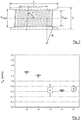
- Figure 1 shows a cross section of the inventive sleeve.
- the sleeve has an overall length 'L' and an outer diameter 'D'. It has an axial bore with axial middle part with minimal diameter 'd min ' and length 'l'.
- the openings at either end are chamfered and show a radius of curvature of 'R'.
- the middle part is a cylinder co-axial with the axis of the sleeve.
- the chamfering is trumpet shaped with a constant radius of curvature.
- ' ⁇ ' When a threading is present it has a certain pitch angle denoted by ' ⁇ '.
- test sleeves (identified with S3.6/'l') were made of the following dimensions:
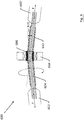
- the sleeves were subjected to a fatigue test rig 600 as schematically described in Figure 6 .
- a steel cord 604 of type 7x7 with a diameter of 3.5 mm is held taut between rotary drill chucks 602, 602'.
- the tension force 'F' on the cord is held constant at 2000 N (which is about the normal working tension of a sawing cord).
- the axes of the drill chucks 602, 602' are mounted under a small angle 610 of 12°.
- a sleeve under test 606 is mounted in a rotary sleeve holder 608.
- the cord exits at either end of the sleeve holder at 6° relative to the rotary axis of the sleeve holder 608.
- the cord with sleeve is embedded into polyurethane prior to the testing.
- the cord is made to rotate at 400 rpm.
- the number of revolutions till break of the cord is registered for at least five repetitions. Thereafter another sleeve under test is mounted.
- Table I Sleeve Average cycles Standard deviation S3.6/0 128023 54856 S3.6/3 208302 95748 S3.6/5 233462 74899 S3.6/7 155649 39952 S3.6/11 140573 3360
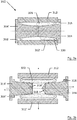
- Sleeves with the above geometry can be made by metal injection moulding as described in figures 3a and 3b .
- a cylindrical mould 310 is made from two half moulds 312, 312' that are joinable at a plane comprising the axis of the sleeve.
- the two half moulds 312, 312' form an outer shell wherein the inner surface shows a surface of revolution with the axis of the sleeve as the axis of revolution.
- First and second metal pins 314 and 314' are insertable from either end of the outer shell.
- the pins have mating ends at 318, 318' that are jointed when inserted into the outer shell.
- the inner surface of the outer shell is provided with an annular rim 330 for filling with polyurethane when the sawing cord is made to provide for a better seal between polyurethane and sleeve.
- Feedstock 320 is injected at high pressure by a standard plunger injection screw through spout hole 316 while vent hole 316' allows for the escape of air and superfluous feedstock.
- the internal cavity of the mould is filled within milliseconds. Thereafter the mould is opened and a green sleeve is obtained.
- the first and second pins 314, 314' are tapered towards the middle and are smooth the pins can be retracted axially from the mould.
- a 'green sleeve' 322 is obtained. This green sleeve can easily be threaded internally as it is still very soft and easily deformable.
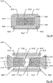
- FIG. 4a An alternative design of the mould 410 is shown in Figure 4a .
- a mould cavity is formed by an outer shell made of two half moulds 412, 412'.
- the first and second pin 414, 414' both show a protruding screw 424 in this case in 'S' direction.
- spout 416 and vent holes 416' are provided.
- the injection in axial direction of the feedstock is preferred as this gives no blemish to the outer surface of the sleeve.
- Green sleeve 422 is now released by screwing first and second pins 414, 414' out of the outer shell, prior to opening the two half moulds 412,412'.
- the unscrewing is done while the green sleeve is still hot in order to prevent gripping of the pins in the green sleeve and to prevent degradation of the threading.
- half-moulds 412, 412' are also provided with a circular recess 413, 413' at either end of the mould cavity. After injection this results in extra material 426, 426' being present at the rim at either end of the sleeve. This extra material 426, 426' reinforces the sleeve and makes it better resistant to impact at entry into the work piece.
- the recesses 413, 413' here have a semi-circular cross section but they can of course have any cross section such as rectangular ar triangular.
- the PolyMIM system allows for water based debinding of the green sleeve (demin water at 40-60°C for about 5 hours, plus 2 hours drying).
- the mold is kept at 40 to 60°C, the temperature of the feedstock at the nozzle at 190°C while an injection pressure of between 750 to 950 is needed.
- Feed rate is between 3 to 25 cm 3 /s
- Feedstock according Catamold® system of BASF (see e.g. US5802437 ):
- the Catamold® system is based on catalytic debinding at 110°C in a HNO 3 environment (afterburn required).
- Sintering cycles are prescribed by the feedstock supplier. Typically they include a hold step for about 1 to 2 hours at 600°C and a 2 to 3 hour hold step at final temperature (1290°C to 1380°C depending on the alloy).
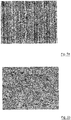
- the sintered sleeves showed a good density of over 95 % of the theoretically possible density. In an metallographic cross section micron sized (1 to 5 ⁇ m) pores remain visible. This is proof that sleeves have been made by metal injection moulding.
- Samples C1,C2, and C3 are made in the conventional way. Samples 11 and 12 were made by metal injection moulding. Sample 11 was a Stainless 316L sample made by the Catamold® route, while sample 12 was made of MIM 17-4PH obtained via the PolyMIM route. There is a marked difference in roughness between both samples: the MIM type samples clearly show a higher roughness than the conventional samples.
- Preliminary laser cladding test showed that the inventive sleeves need 10 to 20% less laser power to start cladding compared to conventional, machined sleeves.
- the inventors attribute this reduction to the increased surface roughness leading to a less specular reflection of the laser beam and thus better coupling-in of the laser energy.
- the sleeves of type S36/5 made of FN02 were successfully used to produce sawing beads by means of laser cladding.
- the sleeves were used on cord of type 7x7 of diameter 3.5.
- the outer strands in this cord were laid in direction 'Z' opposite to the 'S' threading inside the sleeve.
Priority Applications (2)
| Application Number | Priority Date | Filing Date | Title |
|---|---|---|---|
| PL13792656T PL2925473T3 (pl) | 2012-11-30 | 2013-11-15 | Tuleja na koralik do piłowania uzyskiwana za pomocą formowania wtryskowego metalu |
| EP13792656.4A EP2925473B1 (en) | 2012-11-30 | 2013-11-15 | A sleeve for a sawing bead obtained by metal injection moulding |
Applications Claiming Priority (3)
| Application Number | Priority Date | Filing Date | Title |
|---|---|---|---|
| EP12195008 | 2012-11-30 | ||
| EP13792656.4A EP2925473B1 (en) | 2012-11-30 | 2013-11-15 | A sleeve for a sawing bead obtained by metal injection moulding |
| PCT/EP2013/073905 WO2014082870A1 (en) | 2012-11-30 | 2013-11-15 | A sleeve for a sawing bead obtained by metal injection moulding |
Publications (2)
| Publication Number | Publication Date |
|---|---|
| EP2925473A1 EP2925473A1 (en) | 2015-10-07 |
| EP2925473B1 true EP2925473B1 (en) | 2018-02-21 |
Family
ID=47594338
Family Applications (1)
| Application Number | Title | Priority Date | Filing Date |
|---|---|---|---|
| EP13792656.4A Not-in-force EP2925473B1 (en) | 2012-11-30 | 2013-11-15 | A sleeve for a sawing bead obtained by metal injection moulding |
Country Status (9)
| Country | Link |
|---|---|
| US (1) | US9827690B2 (zh) |
| EP (1) | EP2925473B1 (zh) |
| CN (1) | CN104884203B (zh) |
| BR (1) | BR112015012508B1 (zh) |
| ES (1) | ES2662573T3 (zh) |
| PL (1) | PL2925473T3 (zh) |
| PT (1) | PT2925473T (zh) |
| TR (1) | TR201807003T4 (zh) |
| WO (1) | WO2014082870A1 (zh) |
Families Citing this family (11)
| Publication number | Priority date | Publication date | Assignee | Title |
|---|---|---|---|---|
| US10377053B1 (en) * | 2010-06-29 | 2019-08-13 | Bisso Marine, LLC | Cutting apparatus and method |
| CN104884203B (zh) * | 2012-11-30 | 2017-10-03 | 贝卡尔特公司 | 一种制造用作锯珠的磨料层的载体的金属套筒的方法 |
| WO2014166786A1 (en) | 2013-04-10 | 2014-10-16 | Nv Bekaert Sa | Sawing beads and method for making the same |
| ITVI20130192A1 (it) * | 2013-07-29 | 2015-01-30 | Ilario Bidese | Metodo per la realizzazione di supporti tubolari per le perle diamantate di un filo di taglio per materiale lapideo |
| WO2015168332A2 (en) * | 2014-04-30 | 2015-11-05 | Osseodyne Surgical Solutions, Llc | Osseointegrative surgical implant |
| US20170189978A1 (en) * | 2014-05-27 | 2017-07-06 | Nv Bekaert Sa | Metal sleeve for carrying the abrasive layer of a saw bead in a saw cord |
| CN104191528B (zh) * | 2014-07-31 | 2016-06-22 | 泉州金山石材工具科技有限公司 | 一种金刚石串珠及其制造方法 |
| JP6395217B2 (ja) * | 2014-12-12 | 2018-09-26 | 住友電工焼結合金株式会社 | 焼結部品の製造方法 |
| ITUA20163683A1 (it) * | 2016-05-23 | 2017-11-23 | Bonomi Srl | Catena da taglio per il taglio di calcestruzzo armato ed altro |
| EP3580004A1 (en) | 2017-02-08 | 2019-12-18 | NV Bekaert SA | Saw beads with reduced flattening behavior and a saw cord comprising such beads |
| CN113523277B (zh) * | 2021-07-15 | 2022-11-18 | 山东宝元硬质合金有限公司 | 一种通过两次压制实现成型的成型方法 |
Family Cites Families (16)
| Publication number | Priority date | Publication date | Assignee | Title |
|---|---|---|---|---|
| US1909344A (en) * | 1930-02-24 | 1933-05-16 | Roeblings John A Sons Co | Attachment for wire ropes |
| GB2243094A (en) * | 1990-04-17 | 1991-10-23 | Neil George Reid | Wire saws |
| DE4435904A1 (de) * | 1994-10-07 | 1996-04-11 | Basf Ag | Verfahren und Spritzgußmasse für die Herstellung metallischer Formkörper |
| IT235789Y1 (it) * | 1995-02-23 | 2000-07-18 | Veglio Hs Srl | Filo diamantato per il taglio di pietre. |
| DE19522655A1 (de) | 1995-06-22 | 1997-01-02 | Hubert Hillmaier | Diamantsägeseil |
| JPH09314544A (ja) | 1996-05-28 | 1997-12-09 | Asahi Daiyamondo Kogyo Kk | ワイヤソー |
| JPH106329A (ja) * | 1996-06-21 | 1998-01-13 | Asahi Daiyamondo Kogyo Kk | ワイヤソーかしめ用スリーブ |
| JP2955754B1 (ja) * | 1998-06-01 | 1999-10-04 | 有限会社モールドリサーチ | 金属粉末の射出成形用組成物と、その組成物を用いた射出成形及び焼結法 |
| JP2000176737A (ja) * | 1998-12-18 | 2000-06-27 | Asahi Diamond Industrial Co Ltd | ワイヤソービーズ及びその製造方法 |
| MXPA05003960A (es) * | 2002-10-29 | 2005-06-22 | Basf Ag | Material de moldeo por inyeccion de metal y pieza moldeada por inyeccion de metal. |
| ITVR20060016A1 (it) * | 2006-01-23 | 2007-07-24 | Aros Srl | Procedimento per la realizzazione di un elemento anulare di abrasione o perla per un filo da taglio per materiali relativamente duri |
| IN2012DN03295A (zh) * | 2009-11-17 | 2015-10-23 | Bekaert Sa Nv | |
| ES2618914T3 (es) | 2011-03-04 | 2017-06-22 | Nv Bekaert Sa | Método para producir un perla de aserrado |
| EP2495062A1 (en) * | 2011-03-04 | 2012-09-05 | NV Bekaert SA | Sawing Bead |
| KR20140110894A (ko) | 2012-01-05 | 2014-09-17 | 엔브이 베카에르트 에스에이 | 와이어 쏘오용 사출 몰드, 와이어 쏘오의 제조 방법 및 이로부터 제조되는 와이어 쏘오 |
| CN104884203B (zh) * | 2012-11-30 | 2017-10-03 | 贝卡尔特公司 | 一种制造用作锯珠的磨料层的载体的金属套筒的方法 |
-
2013
- 2013-11-15 CN CN201380068954.XA patent/CN104884203B/zh not_active Expired - Fee Related
- 2013-11-15 EP EP13792656.4A patent/EP2925473B1/en not_active Not-in-force
- 2013-11-15 BR BR112015012508-5A patent/BR112015012508B1/pt not_active IP Right Cessation
- 2013-11-15 WO PCT/EP2013/073905 patent/WO2014082870A1/en active Application Filing
- 2013-11-15 ES ES13792656.4T patent/ES2662573T3/es active Active
- 2013-11-15 PL PL13792656T patent/PL2925473T3/pl unknown
- 2013-11-15 TR TR2018/07003T patent/TR201807003T4/tr unknown
- 2013-11-15 US US14/647,637 patent/US9827690B2/en not_active Expired - Fee Related
- 2013-11-15 PT PT137926564T patent/PT2925473T/pt unknown
Also Published As
| Publication number | Publication date |
|---|---|
| CN104884203A (zh) | 2015-09-02 |
| PL2925473T3 (pl) | 2018-07-31 |
| PT2925473T (pt) | 2018-04-05 |
| TR201807003T4 (tr) | 2018-06-21 |
| ES2662573T3 (es) | 2018-04-09 |
| BR112015012508B1 (pt) | 2022-01-18 |
| CN104884203B (zh) | 2017-10-03 |
| US9827690B2 (en) | 2017-11-28 |
| WO2014082870A1 (en) | 2014-06-05 |
| EP2925473A1 (en) | 2015-10-07 |
| US20150298353A1 (en) | 2015-10-22 |
| BR112015012508A2 (pt) | 2017-07-11 |
Similar Documents
| Publication | Publication Date | Title |
|---|---|---|
| EP2925473B1 (en) | A sleeve for a sawing bead obtained by metal injection moulding | |
| EP3148736B1 (en) | Metal sleeve for carrying the abrasive layer of a saw bead in a saw cord and method to produce the same | |
| US20100266438A1 (en) | Method and device for producing annular, rotationally symmetrical workpieces made of metal and/or ceramic powder | |
| US20080120889A1 (en) | Processing of rifled gun barrels from advanced materials | |
| CA2493445C (fr) | Piece mecanique, et procede de fabrication d'une telle piece mecanique | |
| KR102351841B1 (ko) | 소결 부품의 제조 방법 | |
| CA2762461A1 (en) | Process for producing shaped metal bodies having a structured surface | |
| US20020178862A1 (en) | Tungsten-carbide articles made by metal injection molding and method | |
| WO2013150855A1 (ja) | 鋳造用部材及びその製造方法、ダイカスト用スリーブ、並びにダイカスト装置 | |
| CN105855534A (zh) | 粉末冶金用金属粉末、复合物、造粒粉末及烧结体 | |
| EP0651166B1 (fr) | Procédé de fabrication de pieces frittées conjuguées | |
| EP2840155B1 (en) | Magnesium alloy member and method for manufacturing same | |
| JP3681354B2 (ja) | 金属基複合材と、それを用いたピストン | |
| CN112292223B (zh) | 金刚石接合体和金刚石接合体的制造方法 | |
| US20150336172A1 (en) | A method of producing a metallic body provided with a metallic cladding | |
| JPS61186406A (ja) | 耐摩耗性および耐食性にすぐれた射出成形機用ノズルおよびその製造方法 | |
| EP3677402A1 (en) | Molding-machine cylinder and method for producing same | |
| CN115007865B (zh) | 一种碳纳米管化学镀镍增强镍基合金衬套的制备工艺 | |
| EP0163718A1 (en) | A method for manufacturing a tool suitable for cutting and/or shaping work, and a tool which has preferably been manufactured in accordance with the method | |
| CN117506230B (zh) | 一种焊条焊芯和耐磨堆焊焊条 | |
| JPS61218869A (ja) | 耐摩耗性および耐食性にすぐれたシリンダ−およびその製造方法 | |
| US2941281A (en) | Hot workable, heat resistant metal bodies | |
| Zhang et al. | Joining of two materials by powder injection moulding | |
| Harvey | Mechanical design and manufacture of microwave structures | |
| SU1368599A1 (ru) | Способ изготовлени футеровочного элемента |
Legal Events
| Date | Code | Title | Description |
|---|---|---|---|
| PUAI | Public reference made under article 153(3) epc to a published international application that has entered the european phase |
Free format text: ORIGINAL CODE: 0009012 |
|
| 17P | Request for examination filed |
Effective date: 20150508 |
|
| AK | Designated contracting states |
Kind code of ref document: A1 Designated state(s): AL AT BE BG CH CY CZ DE DK EE ES FI FR GB GR HR HU IE IS IT LI LT LU LV MC MK MT NL NO PL PT RO RS SE SI SK SM TR |
|
| AX | Request for extension of the european patent |
Extension state: BA ME |
|
| DAX | Request for extension of the european patent (deleted) | ||
| 17Q | First examination report despatched |
Effective date: 20170206 |
|
| REG | Reference to a national code |
Ref country code: DE Ref legal event code: R079 Ref document number: 602013033415 Country of ref document: DE Free format text: PREVIOUS MAIN CLASS: B23D0061180000 Ipc: B22F0003000000 |
|
| GRAP | Despatch of communication of intention to grant a patent |
Free format text: ORIGINAL CODE: EPIDOSNIGR1 |
|
| RIC1 | Information provided on ipc code assigned before grant |
Ipc: B28D 1/12 20060101ALI20170914BHEP Ipc: B23D 65/00 20060101ALI20170914BHEP Ipc: B22F 5/10 20060101ALI20170914BHEP Ipc: B23D 61/18 20060101ALI20170914BHEP Ipc: B22F 3/12 20060101ALI20170914BHEP Ipc: B22F 3/00 20060101AFI20170914BHEP |
|
| INTG | Intention to grant announced |
Effective date: 20171010 |
|
| GRAS | Grant fee paid |
Free format text: ORIGINAL CODE: EPIDOSNIGR3 |
|
| GRAA | (expected) grant |
Free format text: ORIGINAL CODE: 0009210 |
|
| AK | Designated contracting states |
Kind code of ref document: B1 Designated state(s): AL AT BE BG CH CY CZ DE DK EE ES FI FR GB GR HR HU IE IS IT LI LT LU LV MC MK MT NL NO PL PT RO RS SE SI SK SM TR |
|
| REG | Reference to a national code |
Ref country code: GB Ref legal event code: FG4D |
|
| REG | Reference to a national code |
Ref country code: CH Ref legal event code: EP |
|
| REG | Reference to a national code |
Ref country code: AT Ref legal event code: REF Ref document number: 971155 Country of ref document: AT Kind code of ref document: T Effective date: 20180315 |
|
| REG | Reference to a national code |
Ref country code: IE Ref legal event code: FG4D |
|
| REG | Reference to a national code |
Ref country code: DE Ref legal event code: R096 Ref document number: 602013033415 Country of ref document: DE |
|
| REG | Reference to a national code |
Ref country code: PT Ref legal event code: SC4A Ref document number: 2925473 Country of ref document: PT Date of ref document: 20180405 Kind code of ref document: T Free format text: AVAILABILITY OF NATIONAL TRANSLATION Effective date: 20180328 |
|
| REG | Reference to a national code |
Ref country code: ES Ref legal event code: FG2A Ref document number: 2662573 Country of ref document: ES Kind code of ref document: T3 Effective date: 20180409 |
|
| REG | Reference to a national code |
Ref country code: NL Ref legal event code: MP Effective date: 20180221 |
|
| REG | Reference to a national code |
Ref country code: LT Ref legal event code: MG4D |
|
| PG25 | Lapsed in a contracting state [announced via postgrant information from national office to epo] |
Ref country code: FI Free format text: LAPSE BECAUSE OF FAILURE TO SUBMIT A TRANSLATION OF THE DESCRIPTION OR TO PAY THE FEE WITHIN THE PRESCRIBED TIME-LIMIT Effective date: 20180221 Ref country code: CY Free format text: LAPSE BECAUSE OF FAILURE TO SUBMIT A TRANSLATION OF THE DESCRIPTION OR TO PAY THE FEE WITHIN THE PRESCRIBED TIME-LIMIT Effective date: 20180221 Ref country code: LT Free format text: LAPSE BECAUSE OF FAILURE TO SUBMIT A TRANSLATION OF THE DESCRIPTION OR TO PAY THE FEE WITHIN THE PRESCRIBED TIME-LIMIT Effective date: 20180221 Ref country code: HR Free format text: LAPSE BECAUSE OF FAILURE TO SUBMIT A TRANSLATION OF THE DESCRIPTION OR TO PAY THE FEE WITHIN THE PRESCRIBED TIME-LIMIT Effective date: 20180221 Ref country code: NL Free format text: LAPSE BECAUSE OF FAILURE TO SUBMIT A TRANSLATION OF THE DESCRIPTION OR TO PAY THE FEE WITHIN THE PRESCRIBED TIME-LIMIT Effective date: 20180221 Ref country code: NO Free format text: LAPSE BECAUSE OF FAILURE TO SUBMIT A TRANSLATION OF THE DESCRIPTION OR TO PAY THE FEE WITHIN THE PRESCRIBED TIME-LIMIT Effective date: 20180521 |
|
| PG25 | Lapsed in a contracting state [announced via postgrant information from national office to epo] |
Ref country code: BG Free format text: LAPSE BECAUSE OF FAILURE TO SUBMIT A TRANSLATION OF THE DESCRIPTION OR TO PAY THE FEE WITHIN THE PRESCRIBED TIME-LIMIT Effective date: 20180521 Ref country code: RS Free format text: LAPSE BECAUSE OF FAILURE TO SUBMIT A TRANSLATION OF THE DESCRIPTION OR TO PAY THE FEE WITHIN THE PRESCRIBED TIME-LIMIT Effective date: 20180221 Ref country code: LV Free format text: LAPSE BECAUSE OF FAILURE TO SUBMIT A TRANSLATION OF THE DESCRIPTION OR TO PAY THE FEE WITHIN THE PRESCRIBED TIME-LIMIT Effective date: 20180221 Ref country code: SE Free format text: LAPSE BECAUSE OF FAILURE TO SUBMIT A TRANSLATION OF THE DESCRIPTION OR TO PAY THE FEE WITHIN THE PRESCRIBED TIME-LIMIT Effective date: 20180221 Ref country code: GR Free format text: LAPSE BECAUSE OF FAILURE TO SUBMIT A TRANSLATION OF THE DESCRIPTION OR TO PAY THE FEE WITHIN THE PRESCRIBED TIME-LIMIT Effective date: 20180522 |
|
| PG25 | Lapsed in a contracting state [announced via postgrant information from national office to epo] |
Ref country code: EE Free format text: LAPSE BECAUSE OF FAILURE TO SUBMIT A TRANSLATION OF THE DESCRIPTION OR TO PAY THE FEE WITHIN THE PRESCRIBED TIME-LIMIT Effective date: 20180221 Ref country code: RO Free format text: LAPSE BECAUSE OF FAILURE TO SUBMIT A TRANSLATION OF THE DESCRIPTION OR TO PAY THE FEE WITHIN THE PRESCRIBED TIME-LIMIT Effective date: 20180221 Ref country code: AL Free format text: LAPSE BECAUSE OF FAILURE TO SUBMIT A TRANSLATION OF THE DESCRIPTION OR TO PAY THE FEE WITHIN THE PRESCRIBED TIME-LIMIT Effective date: 20180221 |
|
| REG | Reference to a national code |
Ref country code: DE Ref legal event code: R097 Ref document number: 602013033415 Country of ref document: DE |
|
| PG25 | Lapsed in a contracting state [announced via postgrant information from national office to epo] |
Ref country code: DK Free format text: LAPSE BECAUSE OF FAILURE TO SUBMIT A TRANSLATION OF THE DESCRIPTION OR TO PAY THE FEE WITHIN THE PRESCRIBED TIME-LIMIT Effective date: 20180221 Ref country code: SK Free format text: LAPSE BECAUSE OF FAILURE TO SUBMIT A TRANSLATION OF THE DESCRIPTION OR TO PAY THE FEE WITHIN THE PRESCRIBED TIME-LIMIT Effective date: 20180221 Ref country code: SM Free format text: LAPSE BECAUSE OF FAILURE TO SUBMIT A TRANSLATION OF THE DESCRIPTION OR TO PAY THE FEE WITHIN THE PRESCRIBED TIME-LIMIT Effective date: 20180221 Ref country code: CZ Free format text: LAPSE BECAUSE OF FAILURE TO SUBMIT A TRANSLATION OF THE DESCRIPTION OR TO PAY THE FEE WITHIN THE PRESCRIBED TIME-LIMIT Effective date: 20180221 |
|
| PLBE | No opposition filed within time limit |
Free format text: ORIGINAL CODE: 0009261 |
|
| STAA | Information on the status of an ep patent application or granted ep patent |
Free format text: STATUS: NO OPPOSITION FILED WITHIN TIME LIMIT |
|
| 26N | No opposition filed |
Effective date: 20181122 |
|
| PGFP | Annual fee paid to national office [announced via postgrant information from national office to epo] |
Ref country code: HU Payment date: 20181203 Year of fee payment: 6 |
|
| PG25 | Lapsed in a contracting state [announced via postgrant information from national office to epo] |
Ref country code: SI Free format text: LAPSE BECAUSE OF FAILURE TO SUBMIT A TRANSLATION OF THE DESCRIPTION OR TO PAY THE FEE WITHIN THE PRESCRIBED TIME-LIMIT Effective date: 20180221 |
|
| PGFP | Annual fee paid to national office [announced via postgrant information from national office to epo] |
Ref country code: TR Payment date: 20181025 Year of fee payment: 6 |
|
| REG | Reference to a national code |
Ref country code: CH Ref legal event code: PL |
|
| GBPC | Gb: european patent ceased through non-payment of renewal fee |
Effective date: 20181115 |
|
| PG25 | Lapsed in a contracting state [announced via postgrant information from national office to epo] |
Ref country code: MC Free format text: LAPSE BECAUSE OF FAILURE TO SUBMIT A TRANSLATION OF THE DESCRIPTION OR TO PAY THE FEE WITHIN THE PRESCRIBED TIME-LIMIT Effective date: 20180221 Ref country code: LU Free format text: LAPSE BECAUSE OF NON-PAYMENT OF DUE FEES Effective date: 20181115 |
|
| PGFP | Annual fee paid to national office [announced via postgrant information from national office to epo] |
Ref country code: PL Payment date: 20181105 Year of fee payment: 6 |
|
| REG | Reference to a national code |
Ref country code: IE Ref legal event code: MM4A |
|
| PG25 | Lapsed in a contracting state [announced via postgrant information from national office to epo] |
Ref country code: LI Free format text: LAPSE BECAUSE OF NON-PAYMENT OF DUE FEES Effective date: 20181130 Ref country code: CH Free format text: LAPSE BECAUSE OF NON-PAYMENT OF DUE FEES Effective date: 20181130 |
|
| REG | Reference to a national code |
Ref country code: AT Ref legal event code: UEP Ref document number: 971155 Country of ref document: AT Kind code of ref document: T Effective date: 20180221 |
|
| PG25 | Lapsed in a contracting state [announced via postgrant information from national office to epo] |
Ref country code: FR Free format text: LAPSE BECAUSE OF NON-PAYMENT OF DUE FEES Effective date: 20181130 Ref country code: IE Free format text: LAPSE BECAUSE OF NON-PAYMENT OF DUE FEES Effective date: 20181115 |
|
| PG25 | Lapsed in a contracting state [announced via postgrant information from national office to epo] |
Ref country code: GB Free format text: LAPSE BECAUSE OF NON-PAYMENT OF DUE FEES Effective date: 20181115 |
|
| REG | Reference to a national code |
Ref country code: AT Ref legal event code: MM01 Ref document number: 971155 Country of ref document: AT Kind code of ref document: T Effective date: 20181115 |
|
| PG25 | Lapsed in a contracting state [announced via postgrant information from national office to epo] |
Ref country code: MT Free format text: LAPSE BECAUSE OF NON-PAYMENT OF DUE FEES Effective date: 20181115 Ref country code: AT Free format text: LAPSE BECAUSE OF NON-PAYMENT OF DUE FEES Effective date: 20181115 |
|
| PG25 | Lapsed in a contracting state [announced via postgrant information from national office to epo] |
Ref country code: HU Free format text: LAPSE BECAUSE OF FAILURE TO SUBMIT A TRANSLATION OF THE DESCRIPTION OR TO PAY THE FEE WITHIN THE PRESCRIBED TIME-LIMIT; INVALID AB INITIO Effective date: 20131115 Ref country code: MK Free format text: LAPSE BECAUSE OF NON-PAYMENT OF DUE FEES Effective date: 20180221 |
|
| PG25 | Lapsed in a contracting state [announced via postgrant information from national office to epo] |
Ref country code: PT Free format text: LAPSE BECAUSE OF NON-PAYMENT OF DUE FEES Effective date: 20200618 Ref country code: IS Free format text: LAPSE BECAUSE OF FAILURE TO SUBMIT A TRANSLATION OF THE DESCRIPTION OR TO PAY THE FEE WITHIN THE PRESCRIBED TIME-LIMIT Effective date: 20180621 |
|
| PGFP | Annual fee paid to national office [announced via postgrant information from national office to epo] |
Ref country code: DE Payment date: 20201119 Year of fee payment: 8 Ref country code: IT Payment date: 20201124 Year of fee payment: 8 |
|
| PGFP | Annual fee paid to national office [announced via postgrant information from national office to epo] |
Ref country code: BE Payment date: 20201125 Year of fee payment: 8 |
|
| PGFP | Annual fee paid to national office [announced via postgrant information from national office to epo] |
Ref country code: ES Payment date: 20210122 Year of fee payment: 8 |
|
| PG25 | Lapsed in a contracting state [announced via postgrant information from national office to epo] |
Ref country code: PL Free format text: LAPSE BECAUSE OF NON-PAYMENT OF DUE FEES Effective date: 20191115 |
|
| REG | Reference to a national code |
Ref country code: DE Ref legal event code: R119 Ref document number: 602013033415 Country of ref document: DE |
|
| PG25 | Lapsed in a contracting state [announced via postgrant information from national office to epo] |
Ref country code: TR Free format text: LAPSE BECAUSE OF NON-PAYMENT OF DUE FEES Effective date: 20191115 |
|
| PG25 | Lapsed in a contracting state [announced via postgrant information from national office to epo] |
Ref country code: BE Free format text: LAPSE BECAUSE OF NON-PAYMENT OF DUE FEES Effective date: 20211130 |
|
| REG | Reference to a national code |
Ref country code: BE Ref legal event code: MM Effective date: 20211130 |
|
| PG25 | Lapsed in a contracting state [announced via postgrant information from national office to epo] |
Ref country code: DE Free format text: LAPSE BECAUSE OF NON-PAYMENT OF DUE FEES Effective date: 20220601 |
|
| PG25 | Lapsed in a contracting state [announced via postgrant information from national office to epo] |
Ref country code: IT Free format text: LAPSE BECAUSE OF NON-PAYMENT OF DUE FEES Effective date: 20211115 |
|
| REG | Reference to a national code |
Ref country code: ES Ref legal event code: FD2A Effective date: 20230224 |
|
| PG25 | Lapsed in a contracting state [announced via postgrant information from national office to epo] |
Ref country code: ES Free format text: LAPSE BECAUSE OF NON-PAYMENT OF DUE FEES Effective date: 20211116 |