EP2924839A1 - Régime de secours monophasé d'un onduleur triphasé et onduleur correspondant - Google Patents
Régime de secours monophasé d'un onduleur triphasé et onduleur correspondant Download PDFInfo
- Publication number
- EP2924839A1 EP2924839A1 EP15158984.3A EP15158984A EP2924839A1 EP 2924839 A1 EP2924839 A1 EP 2924839A1 EP 15158984 A EP15158984 A EP 15158984A EP 2924839 A1 EP2924839 A1 EP 2924839A1
- Authority
- EP
- European Patent Office
- Prior art keywords
- phase
- power
- network
- inverter
- bridge branches
- Prior art date
- Legal status (The legal status is an assumption and is not a legal conclusion. Google has not performed a legal analysis and makes no representation as to the accuracy of the status listed.)
- Granted
Links
- 238000000034 method Methods 0.000 claims abstract description 51
- 230000007935 neutral effect Effects 0.000 description 16
- 238000009434 installation Methods 0.000 description 6
- 239000004020 conductor Substances 0.000 description 5
- 239000003990 capacitor Substances 0.000 description 4
- 238000012806 monitoring device Methods 0.000 description 4
- 239000004065 semiconductor Substances 0.000 description 4
- 230000008878 coupling Effects 0.000 description 3
- 238000010168 coupling process Methods 0.000 description 3
- 238000005859 coupling reaction Methods 0.000 description 3
- 230000008569 process Effects 0.000 description 3
- 238000000926 separation method Methods 0.000 description 3
- 230000008859 change Effects 0.000 description 2
- 150000001875 compounds Chemical class 0.000 description 2
- 238000010586 diagram Methods 0.000 description 2
- 230000001960 triggered effect Effects 0.000 description 2
- 230000004913 activation Effects 0.000 description 1
- 230000002457 bidirectional effect Effects 0.000 description 1
- 238000006243 chemical reaction Methods 0.000 description 1
- 238000004891 communication Methods 0.000 description 1
- 230000001419 dependent effect Effects 0.000 description 1
- 238000011161 development Methods 0.000 description 1
- 230000018109 developmental process Effects 0.000 description 1
- 238000011017 operating method Methods 0.000 description 1
Images

Classifications
-
- H—ELECTRICITY
- H02—GENERATION; CONVERSION OR DISTRIBUTION OF ELECTRIC POWER
- H02J—CIRCUIT ARRANGEMENTS OR SYSTEMS FOR SUPPLYING OR DISTRIBUTING ELECTRIC POWER; SYSTEMS FOR STORING ELECTRIC ENERGY
- H02J9/00—Circuit arrangements for emergency or stand-by power supply, e.g. for emergency lighting
- H02J9/04—Circuit arrangements for emergency or stand-by power supply, e.g. for emergency lighting in which the distribution system is disconnected from the normal source and connected to a standby source
- H02J9/06—Circuit arrangements for emergency or stand-by power supply, e.g. for emergency lighting in which the distribution system is disconnected from the normal source and connected to a standby source with automatic change-over, e.g. UPS systems
- H02J9/062—Circuit arrangements for emergency or stand-by power supply, e.g. for emergency lighting in which the distribution system is disconnected from the normal source and connected to a standby source with automatic change-over, e.g. UPS systems for AC powered loads
-
- H—ELECTRICITY
- H02—GENERATION; CONVERSION OR DISTRIBUTION OF ELECTRIC POWER
- H02M—APPARATUS FOR CONVERSION BETWEEN AC AND AC, BETWEEN AC AND DC, OR BETWEEN DC AND DC, AND FOR USE WITH MAINS OR SIMILAR POWER SUPPLY SYSTEMS; CONVERSION OF DC OR AC INPUT POWER INTO SURGE OUTPUT POWER; CONTROL OR REGULATION THEREOF
- H02M7/00—Conversion of ac power input into dc power output; Conversion of dc power input into ac power output
- H02M7/42—Conversion of dc power input into ac power output without possibility of reversal
- H02M7/44—Conversion of dc power input into ac power output without possibility of reversal by static converters
- H02M7/48—Conversion of dc power input into ac power output without possibility of reversal by static converters using discharge tubes with control electrode or semiconductor devices with control electrode
- H02M7/483—Converters with outputs that each can have more than two voltages levels
- H02M7/487—Neutral point clamped inverters
-
- Y—GENERAL TAGGING OF NEW TECHNOLOGICAL DEVELOPMENTS; GENERAL TAGGING OF CROSS-SECTIONAL TECHNOLOGIES SPANNING OVER SEVERAL SECTIONS OF THE IPC; TECHNICAL SUBJECTS COVERED BY FORMER USPC CROSS-REFERENCE ART COLLECTIONS [XRACs] AND DIGESTS
- Y02—TECHNOLOGIES OR APPLICATIONS FOR MITIGATION OR ADAPTATION AGAINST CLIMATE CHANGE
- Y02B—CLIMATE CHANGE MITIGATION TECHNOLOGIES RELATED TO BUILDINGS, e.g. HOUSING, HOUSE APPLIANCES OR RELATED END-USER APPLICATIONS
- Y02B10/00—Integration of renewable energy sources in buildings
- Y02B10/70—Hybrid systems, e.g. uninterruptible or back-up power supplies integrating renewable energies
-
- Y—GENERAL TAGGING OF NEW TECHNOLOGICAL DEVELOPMENTS; GENERAL TAGGING OF CROSS-SECTIONAL TECHNOLOGIES SPANNING OVER SEVERAL SECTIONS OF THE IPC; TECHNICAL SUBJECTS COVERED BY FORMER USPC CROSS-REFERENCE ART COLLECTIONS [XRACs] AND DIGESTS
- Y02—TECHNOLOGIES OR APPLICATIONS FOR MITIGATION OR ADAPTATION AGAINST CLIMATE CHANGE
- Y02E—REDUCTION OF GREENHOUSE GAS [GHG] EMISSIONS, RELATED TO ENERGY GENERATION, TRANSMISSION OR DISTRIBUTION
- Y02E10/00—Energy generation through renewable energy sources
- Y02E10/50—Photovoltaic [PV] energy
- Y02E10/56—Power conversion systems, e.g. maximum power point trackers
Definitions
- the invention relates to a method for operating an inverter, in particular a photovoltaic inverter, in order to provide a single-phase AC power for supplying consumers in an emergency operation, and an inverter, which by means of the method in an emergency operation, a single-phase AC power provides for the supply of consumers.
- DC power DC
- AC power Alternating Current
- photovoltaic inverters which transform the DC power of a photovoltaic generator, here referred to as photovoltaic inverters, feed into a larger interconnected grid. Household, industrial or similar consumers are also connected to this interconnected grid and, depending on their power consumption, require different voltages for their operation.
- backup systems or "uninterruptible power supplies” are known, for example, here is the DE 10 2011 000 394 A1 called.
- a battery and another inverter are connected to the local grid of the house or the industrial plant connected in order to provide a local island network after failure of the interconnected network and after separation of the local network from the interconnected network by means of the further inverter and to cover a base load with the energy stored in the battery. This means that some consumers can be safely supplied with the stored energy.
- the local grid allows the photovoltaic inverters to feed back into a grid without their having to adapt their regulation to the island situation.
- the document shows DE 10 2005 008 809 A1 an inverter for feeding into a power grid, the three bridge arms are individually switched on and off.
- a comparable inverter discloses the document US 2011/0267857 , which can implement either a single-phase, a two-phase or a three-phase feed into a network.
- a method according to the invention is arranged for converting DC power of a source into AC power by means of an inverter comprising three bridge branches each having a phase output.
- the DC power is preferably provided by a photovoltaic generator.
- the bridge arms are controlled in such a way that the AC power is fed as a three-phase grid-conforming power into a grid.
- Three-phase systems are referred to here, which work with three alternating currents or alternating voltages of the same frequency, which are mutually shifted in their phase angles by 120 °, in which, also known as "three-phase system” systems, the neutral point must not be grounded.
- network-conforming conditions is meant that the conditions of the grid operator (Grid Code) are complied with at the place of supply.
- the inverter If the inverter is disconnected from the grid, for example, because the interconnected network is disturbed, faulty or turned off, an emergency operation is realized.
- AC power is provided as a single-phase isolated grid at two of the three phase outputs. This operation is also referred to here as isolated operation.
- the inverter builds a single-phase stand-alone grid, which means that the voltage level and frequency are now specified by the inverter. So single-phase consumers can be supplied.
- a single-phase island network is provided by a part of the inverter bridge branches present in the inverter, without the need for further components or devices.
- the three bridge branches of the inverter are driven in the network-bound operation in a first cycle.
- two of the three inverter bridge branches are driven in a second clocking process, the first and second clocking methods being different.
- a three-phase AC power is fed only by means of different clock methods in network operation, while in island operation a single-phase AC power is provided to supply consumers.
- a peak voltage between the two phase outputs, at which single-phase isolated network is provided in the island mode is different from a peak voltage between the same two phase outputs in the network-connected mode.
- the peak voltage is generally understood as the maximum value of an alternating voltage, as a reference value for the Connection of consumers to an AC voltage network is usually the effective value of the voltage specified, RMS values and peak voltage can be converted into each other in a known manner by means of a factor.
- the voltage between any two phase outputs in a three-phase operation is different than the voltage required by single-phase loads.
- consumers with high power consumption often require a three-phase three-phase connection, while domestic small consumers are operated with a single-phase connection.
- the first clock method is an N-level clock method, where N> 2 and the second clock method is a two-level clock method. Because of their greater efficiency, three-phase systems in particular often use multi-level topologies, which are operated using the corresponding clocking methods. In island operation, some of the switches will not be clocked and will be switched to a two-level clocking process.
- the single-phase AC power is provided in the island operation at the same connection point for consumers as in network-connected operation.
- the phase outputs can be switched locally to the supply lines of the consumers so that the consumers do not have to be reconnected to a special power outlet. They remain in their place and are supplied by the same supply line of the house installation.
- the two phase outputs which provide the single-phase AC power are switched to a different output. If connection conditions of supervisory authorities do not permit switching of the supply lines, as mentioned above, or if, for example, a supply in the island operation is demanded in Japan, the single-phase AC power can also be separated to another, for example, from the rest of the domestic installation , Output are switched. In this way, no changes to the existing house installation are needed.
- one of the phase outputs is connected to the ground potential in the island operation.
- single-phase loads are operated between a phase and a grounded neutral. There is no need to connect to a neutral to provide three-phase AC power. If a single-phase AC power with neutral reference is to be provided in stand-alone operation, then a connection from one of the phase outputs to the ground potential must be established.
- An inverter converts DC power of a source into AC power. It comprises three bridge branches, each with a phase output. Between the source of the DC power and the bridge arms an intermediate circuit is arranged, which consists for example of one or more capacitors and is able to store energy. The DC link potential is displaceable relative to the ground potential, which means in particular that the DC link is not earthed. Thus, the inverter according to the invention requires no neutral connection for three-phase operation.
- an inverter according to the invention may be a photovoltaic inverter which converts DC power of a photovoltaic generator at its input into AC power and provides it at its output.
- the displaceable DC link potential brings efficiency advantages in the operation of the inverter, since the inverter can be operated in three-phase operation with a lower DC link voltage than with a grounded DC link.
- the DC link voltage can correspond to the maximum potential difference of the three phases, and the DC link potential with respect to the midpoint of the three-phase mains voltage oscillates at 3 times the mains frequency, also called "moving center point voltage".
- the peak voltage between the two phase outputs, at which a single-phase isolated network is provided in the island operation different from the peak voltage between the same two phase outputs in the network operation. Since, in particular, photovoltaic generators have a strongly fluctuating power output due to weather conditions, it may be advantageous to provide only the most important consumers and in particular consumers with a not too large power consumption for island operation. Such consumers are usually operated in single phase and can continue to be operated in the event of a failure of the grid to the inverter of the invention.
- the bridge arms are constructed of at least two semiconductor switches.
- an inventive inverter could be constructed with the so-called B6 topology. Preference is given to using known three or more level topologies, such as Neutral Point Clamped (NPC), Bipolar Switch Neutral Point Clamped (BSNPC), Active Neutral Point Clamped (ANPC) or Flying Capacitor (FLC) that require significantly more semiconductor switches, but often have advantages in terms of their efficiency.
- NPC Neutral Point Clamped
- BSNPC Bipolar Switch Neutral Point Clamped
- ANPC Active Neutral Point Clamped
- FLC Flying Capacitor
- the AC power can be provided by the operation of two switches each in each of the two bridge branches used in island operation.
- the remaining switches can be opened, but at least they are not clocked to form the single-phase AC power.
- two switches can each be clocked as a so-called H4 bridge in two of the three bridge branches.
- the single-phase AC power is switched to the same connection point for consumers in island operation, to which they are also connected in network operation.
- consumers can be operated at the same socket as in grid-connected operation.
- the inverter has a switching device for establishing a connection between the two of the three bridge arms, at which the single-phase AC power in island operation and a connection point for consumers.
- the phase outputs can be switched to the supply lines of the consumers in a local network so that the consumers do not have to be reconnected to a special power outlet. They remain in their place and are supplied by the same supply line of the house installation.
- a switching of the single-phase AC power in island operation takes place on a different connection point for the consumers, which is separate from the rest of the local network. If supervisory conditions do not permit switching of the feeder lines or if, as in Japan, a stand-alone supply is required in the island mode, the single-phase AC power can also be switched to another output, for example a socket housed in a separate housing , In this way, no changes to the existing house installation necessary, the separate outlet can be connected via a cable to the inverter and activated automatically or manually if necessary.
- FIG. 1 shows as a first embodiment, an inverter 1 with three bridge branches 4, 5, 6 which is suitable for carrying out the method according to the invention.
- the bridge branches 4, 5, 6 consist here of two switches connected in series, as a rule, these are semiconductor switches, such as IGBT. This switch arrangement is also called B6 topology.
- a network-connected operation that is, when the circuit breaker 11 is closed, the two switches of the bridge branches 4, 5, 6 are operated so clocked by a controller 12 that at the phase outputs 7, 8, 9, here between the two switches of the respective Bridge branches 4, 5, 6 are located, a network-compliant power is fed into a network 10.
- the energy is thereby provided by a source 2, which can provide a DC power, such as a battery or a photovoltaic generator. If it is a rechargeable battery, power can be consumed and output, in which case the inverter 1 must be set up for bidirectional operation.
- the DC power provided by the source 2 is usually buffered by a DC link 13.
- the grid 10 is assumed to be a three-phase grid, therefore, the inverter 1 outputs at the three phase outputs 7, 8, 9, a three-phase AC power whose height and frequency is set by the interconnected network 10.
- the interconnected network 10 may in this case have a grounded star point, but may also be ungrounded.
- the inverter 1 is ungrounded, that is, it has no connection to ground potential, in particular it is not designed in 4-wire topology and has no DC link center, which would be outwardly connected as a terminal and connected to a neutral conductor.
- a network monitoring device 16 monitors the state of the interconnected network 10 by z. B. voltage, frequency and / or phase angle of the interconnected network 10 are measured and compared with normative or network operator specifications. In this way, a failure of the interconnected network 10 can be detected and transmitted to the controller 12 through a wireless or wired communication link. If a failure of the interconnected network 10 is detected, the inverter 1 be separated from the interconnected network 10 by means of disconnector 11. This can both automatically, z. B. triggered by the controller 12, or done manually. After the separation of the inverter 1 from the interconnected network 10, according to the inventive method, single-phase stand-alone network is provided at two of the three phase outputs 7, 8, 9, for example at the phase outputs 7 and 8. For this purpose, the voltage and frequency of the single-phase power supply provided are predetermined by the inverter 1 ,
- single-phase loads are powered by connecting them to a phase and ground potential.
- the interconnected network itself is often a three-phase network, which operates with three alternating currents or alternating voltages of the same frequency, which are shifted from each other in their phase angles by 120 °.
- the voltages between two phases for example, 360 V rms , are then usually greater in the west than the voltage from one phase to ground, for example, 220 V rms , which is why consumers with a higher power consumption are usually connected to all three phases. These consumers can not be operated when using the method according to the invention in emergency mode.
- both the voltage level and the phase position between the phase outputs 7, 8, at which the single-phase AC power is provided in the island mode must be changed at the beginning of the emergency operation.
- the clock pattern, after which the switches of the bridge arms 4, 5, 6 are controlled, must be changed.
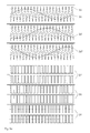
- FIG. 2 a shows a possible embodiment of the clock method for controlling the switches of the inverter 1 in a network-connected operation.
- PWM signals for driving the switches of the bridge branches 4, 5, 6 by the controller 12 in be generated in a known manner by a reference signal 36 is compared with a carrier signal 35.
- the upper three diagrams are assigned to the three phase outputs 7, 8, 9. They represent the respective input variables for the controller 12, the reference signals 36, 36 ', 36 "representing the shape of the desired output voltage, It can be seen that the three reference signals 36, 36', 36" are out of phase with each other by 120 °. This leads to the output of a three-phase power at the three phase outputs 7, 8, 9 of the inverter 1.
- the controller 12 generates PWM signals 37, 38, 39 from the comparison of the respective reference signal 36 and carrier signal 35, which is the same for all phases for the bridge branches 4, 5, 6, wherein, for example, the PWM signals 37 can represent the activation of the two switches of the bridge branch 4.
- FIG. 2b shows a possible embodiment of the clock method for controlling the switches of the inverter 1 in an emergency operation.
- the upper two diagrams are assigned to the two phase outputs 7, 8 at which the single-phase network is to be set.
- a first reference signal 40, a second reference signal 40 'and the carrier signal 35 represent the respective input variables for the controller 12.
- the controller 12 calculates the PMW signals 41 for the switches of the bridge branch 4 second reference signal 40 'and carrier signal 35, the PMW signals 42 of the bridge branch 5.
- the switches of the bridge branch 6 are not driven, as indicated in 43.
- the two reference signals 40, 40 ' are mutually phase-shifted by 180 °.
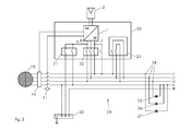
- FIG. 3 shows as another embodiment, an inverter 20 with switching devices 21, 22, 23, which allows consumers 25, 26, 27 at their connection points 28 in a local network 29, such as a power outlet of a domestic installation, during an emergency operation with energy from a source. 2 to supply, for example, a photovoltaic system located on the house.
- all required switching devices 21, 22, 23, for example, as a structural unit, preferably housed in the housing of the inverter 20.
- the switching devices 21, 22, 23 can also be independent Be provided components or, for example, together with the circuit breaker 11, integrated in the service connection box.
- the local network 29 is also a three-phase network in which the loads 25, 26, 27 are connected in three phases in order to achieve a better load distribution.
- the inverter 20 separates by means of its inverter switching device 22 from the local network 29 and separates by controlling the circuit breaker 11 all-pole, the local network 29 with the consumers 25, 26, 27 from Compound network 10, to prevent a later feedback from the inverter 20 in the interconnected network 10.
- the local area network 29 represents a local island network.
- phase output 7 is connected to the phase L1 of the local network 29, the switches on the phase outputs 8, 9 remain open.
- neutral conductor switching device 21 phase output 9 is connected to the neutral conductor N.
- phase output 9 can also be connected directly to earth, the PE connection.
- a coupling switching device 23 can establish a connection between L2 and L3 of the local network 29 to L1, so that in the sequence all the consumers 25, 26, 27 with the phase output 7 of Inverter 20 and are connected via their neutral terminal N to the phase output 9 of the inverter 20. So all consumers are connected to the same single-phase voltage of the isolated grid. Likewise, it is also conceivable to couple only two of the three phases with each other, whereby only part of the consumers would be supplied in emergency mode.
- the network monitoring device 16 further monitors the state of the interconnected network 10.
- the inverter 20 disconnects from the local network 29 by means of its inverter switching device 22, disconnects the phases L2 and L3 with L1 by means of coupling switching device 23, solves the connection of phase output 9 with the neutral conductor N and ground by means of neutral conductor switching device 21 and connects the local network 29 again with the interconnected network 10.
- the inverter 20 resets its clock cycle to "normal operation", synchronizes with the interconnected network 10 and outputs again a three-phase network-compliant performance.
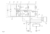
- FIG. 4 shows a further embodiment, an inverter 1 with three bridge branches 4, 5, 6, which is suitable for carrying out the method according to the invention.
- the functioning as a buffer for the DC power DC link 13 is executed here shared, ie it comprises at least two series-connected capacitors.
- the bridge branches 4, 5, 6 each comprise two series-connected bridge switches 44, 45, each with antiparallel-connected diodes 51, 52, wherein the connection point between the two series-connected bridge switches 44, 45 via two parallel series circuits each comprising a midpoint switch 46, 47th and a diode 53, 54 is connected to the center 55 of the divided intermediate circuit 13.
- This arrangement of the switches is also referred to as a BSNPC (bipolar switched neutral point clamped) topology and is a variant of so-called multi-level inverters - especially here "three-level” - which have a particularly good conversion efficiency.
- BSNPC bipolar switched neutral point clamped
- a request switch 61 is provided in this embodiment, with which a user of the controller 12 can signal that an emergency operation is desired.
- the controller 12 can check whether there is a power failure, in principle, it may also depend only on the choice of the user, whether to switch to emergency operation.
- the circuit breaker 11 is first opened, then the clock method is switched so that at the phase outputs 7, 8 a single-phase network by clocking the bridge switch 44, 45, 58, 59 is provided.
- the phase outputs 7, 8 are switched by means of emergency power switch 56, 57 to another connection point 31. Except for the request switch 61 all switching operations are triggered by the controller 12.
- connection point 31 may, for example, be located in a separate, mobile housing with a special socket together with the request switch 61. If the emergency operation function is desired, the user can connect the device 25 of his choice with the other connection point 31 and actuate the request switch 61. Then, the DC power of the source 2, for example, the private PV system, exclusively for the supply of the selected device 25 is used. To switch back to network operation, the request switch 61 is again to operate, the controller 12 sets the clock method back to three-phase, opens the emergency power switch 56, 57 and closes the circuit breaker 11th
- a check of the state of the interconnected network 10 can be provided and the operation of the request switch 61 or the function of the emergency power switches 56, 57 can be disabled in the event that the interconnected network 10 is functional is.
- the topology described here is actuated in network-bound operation in a known three-level clocking method, ie the bridge switches 44, 45 and the center switches 46, 47 of the respective bridge branches can connect the respective phase output 7 with three different potentials. These Potentials are applied to the DC plus pole 17, DC negative pole 18 and the center point 55 of the divided DC link.
- multi-level topologies would also switch between networked operation in a multi-level clocking mode and emergency mode in a two-level clocking mode.
Applications Claiming Priority (1)
| Application Number | Priority Date | Filing Date | Title |
|---|---|---|---|
| DE102014104216.6A DE102014104216B3 (de) | 2014-03-26 | 2014-03-26 | Einphasiger Notbetrieb eines dreiphasigen Wechselrichters und entsprechender Wechselrichter |
Publications (2)
| Publication Number | Publication Date |
|---|---|
| EP2924839A1 true EP2924839A1 (fr) | 2015-09-30 |
| EP2924839B1 EP2924839B1 (fr) | 2016-09-21 |
Family
ID=52706007
Family Applications (1)
| Application Number | Title | Priority Date | Filing Date |
|---|---|---|---|
| EP15158984.3A Active EP2924839B1 (fr) | 2014-03-26 | 2015-03-13 | Régime de secours monophasé d'un onduleur triphasé et onduleur correspondant |
Country Status (5)
| Country | Link |
|---|---|
| US (1) | US9369062B2 (fr) |
| EP (1) | EP2924839B1 (fr) |
| JP (1) | JP6388845B2 (fr) |
| CN (1) | CN104953879B (fr) |
| DE (1) | DE102014104216B3 (fr) |
Families Citing this family (13)
| Publication number | Priority date | Publication date | Assignee | Title |
|---|---|---|---|---|
| DE102013113000A1 (de) * | 2013-11-25 | 2015-05-28 | Sma Solar Technology Ag | Verfahren zum Betreiben eines Wechselrichters und Wechselrichter mit einem Schalter zwischen einem Mittelpunkt eines Gleichspannungszwischenkreises und einem Anschluss für einen Nullleiter eines Wechselstromnetzes |
| JP2015228778A (ja) * | 2014-06-03 | 2015-12-17 | 株式会社日立製作所 | 電力変換装置 |
| EP3252937A1 (fr) | 2016-06-03 | 2017-12-06 | Fronius International GmbH | Onduleur et procédé de fonctionnement d'un onduleur |
| US10050558B2 (en) * | 2016-06-13 | 2018-08-14 | Toyota Industries Electric Systems North America, Inc. | Alternating current (AC) inverter and method of controlling the same |
| CN108270366A (zh) * | 2016-12-30 | 2018-07-10 | 艾思玛新能源技术(江苏)有限公司 | 一种基于三相中点箝位型逆变器的调制方法和装置 |
| DE102017131042A1 (de) | 2017-12-21 | 2019-06-27 | Sma Solar Technology Ag | Umrichter mit mindestens einem wandlermodul mit drei brückenzweigen, verfahren zum betreiben und verwendung eines solchen umrichters |
| CN110071521B (zh) * | 2018-01-23 | 2021-09-03 | 台达电子企业管理(上海)有限公司 | 配电设备及配电方法 |
| US11271406B2 (en) * | 2018-01-24 | 2022-03-08 | Bloom Energy Corporation | Selective grounding of grid parallel inverter systems |
| CN110994968B (zh) | 2019-11-22 | 2021-06-01 | 华为技术有限公司 | 一种预充电电路、逆变器以及发电系统 |
| WO2021191434A1 (fr) | 2020-03-27 | 2021-09-30 | Fronius International Gmbh | Onduleur pouvant commuter entre un fonctionnement monophasé et un fonctionnement triphasé |
| DE102020112723B4 (de) | 2020-05-11 | 2021-11-25 | Sma Solar Technology Ag | Wechselrichter mit drei Brückenzweigen und Verfahren zum Betreiben eines derartigen Wechselrichters |
| CN112564532A (zh) * | 2020-12-16 | 2021-03-26 | 苏州绿控传动科技股份有限公司 | 基于电动汽车逆变器的单相逆变系统 |
| CN116780926B (zh) * | 2023-08-24 | 2023-12-05 | 深圳闻储创新科技有限公司 | 逆变器和逆变器控制方法 |
Citations (10)
| Publication number | Priority date | Publication date | Assignee | Title |
|---|---|---|---|---|
| DE19937410A1 (de) | 1999-08-07 | 2001-02-15 | Elektro & Automatisierungstech | Dreiphasiger Solarwechselrichter für Netz- und Inselbetrieb |
| EP1226996A2 (fr) * | 2001-01-25 | 2002-07-31 | Mitsubishi Heavy Industries, Ltd. | Régulateur pour un chariot de fourche à accumulateur |
| EP1286455A1 (fr) * | 2000-03-08 | 2003-02-26 | Kabushiki Kaisha Yaskawa Denki | Cycloconvertisseur mid et detecteur de pannes electriques |
| EP1443634A2 (fr) * | 2003-01-24 | 2004-08-04 | Toshiba International Corporation | Entraínement à onduleur ayant une configuration pouvant être changée |
| US20050018460A1 (en) * | 2003-07-11 | 2005-01-27 | Tai-Jou Chen | Method and apparatus for implementing same phase power supply scheme |
| DE102005008809A1 (de) | 2005-02-26 | 2006-10-12 | Kostal Industrie Elektrik Gmbh | Wechselrichter |
| US20110267857A1 (en) | 2010-04-29 | 2011-11-03 | Enphase Energy, Inc. | Method and apparatus for distributed power generation |
| DE102011000394A1 (de) | 2011-01-28 | 2012-08-02 | Sma Solar Technology Ag | Lokale Energieversorgungsanlage |
| WO2013004585A1 (fr) | 2011-07-04 | 2013-01-10 | Sma Solar Technology Ag | Procédé pour faire fonctionner un onduleur et onduleur tolérant aux pannes de secteur |
| US20130155736A1 (en) * | 2011-12-16 | 2013-06-20 | Milan Ilic | Bi-directional energy converter with multiple dc sources |
Family Cites Families (4)
| Publication number | Priority date | Publication date | Assignee | Title |
|---|---|---|---|---|
| US6853940B2 (en) * | 2002-01-16 | 2005-02-08 | Ballard Power Systems Corporation | Anti-islanding device and method for grid connected inverters using random noise injection |
| US7427815B1 (en) * | 2003-11-14 | 2008-09-23 | General Electric Company | Method, memory media and apparatus for detection of grid disconnect |
| WO2013080877A1 (fr) * | 2011-11-29 | 2013-06-06 | 三洋電機株式会社 | Dispositif de connexion au réseau électrique |
| JP5755191B2 (ja) * | 2012-07-17 | 2015-07-29 | 三菱電機株式会社 | パワーコンディショナシステム |
-
2014
- 2014-03-26 DE DE102014104216.6A patent/DE102014104216B3/de not_active Expired - Fee Related
-
2015
- 2015-03-13 EP EP15158984.3A patent/EP2924839B1/fr active Active
- 2015-03-17 US US14/660,346 patent/US9369062B2/en active Active
- 2015-03-23 JP JP2015058863A patent/JP6388845B2/ja active Active
- 2015-03-24 CN CN201510129376.7A patent/CN104953879B/zh active Active
Patent Citations (10)
| Publication number | Priority date | Publication date | Assignee | Title |
|---|---|---|---|---|
| DE19937410A1 (de) | 1999-08-07 | 2001-02-15 | Elektro & Automatisierungstech | Dreiphasiger Solarwechselrichter für Netz- und Inselbetrieb |
| EP1286455A1 (fr) * | 2000-03-08 | 2003-02-26 | Kabushiki Kaisha Yaskawa Denki | Cycloconvertisseur mid et detecteur de pannes electriques |
| EP1226996A2 (fr) * | 2001-01-25 | 2002-07-31 | Mitsubishi Heavy Industries, Ltd. | Régulateur pour un chariot de fourche à accumulateur |
| EP1443634A2 (fr) * | 2003-01-24 | 2004-08-04 | Toshiba International Corporation | Entraínement à onduleur ayant une configuration pouvant être changée |
| US20050018460A1 (en) * | 2003-07-11 | 2005-01-27 | Tai-Jou Chen | Method and apparatus for implementing same phase power supply scheme |
| DE102005008809A1 (de) | 2005-02-26 | 2006-10-12 | Kostal Industrie Elektrik Gmbh | Wechselrichter |
| US20110267857A1 (en) | 2010-04-29 | 2011-11-03 | Enphase Energy, Inc. | Method and apparatus for distributed power generation |
| DE102011000394A1 (de) | 2011-01-28 | 2012-08-02 | Sma Solar Technology Ag | Lokale Energieversorgungsanlage |
| WO2013004585A1 (fr) | 2011-07-04 | 2013-01-10 | Sma Solar Technology Ag | Procédé pour faire fonctionner un onduleur et onduleur tolérant aux pannes de secteur |
| US20130155736A1 (en) * | 2011-12-16 | 2013-06-20 | Milan Ilic | Bi-directional energy converter with multiple dc sources |
Also Published As
| Publication number | Publication date |
|---|---|
| DE102014104216B3 (de) | 2015-06-11 |
| JP2015188307A (ja) | 2015-10-29 |
| US9369062B2 (en) | 2016-06-14 |
| CN104953879A (zh) | 2015-09-30 |
| US20150280607A1 (en) | 2015-10-01 |
| EP2924839B1 (fr) | 2016-09-21 |
| CN104953879B (zh) | 2018-06-26 |
| JP6388845B2 (ja) | 2018-09-12 |
Similar Documents
| Publication | Publication Date | Title |
|---|---|---|
| EP2924839B1 (fr) | Régime de secours monophasé d'un onduleur triphasé et onduleur correspondant | |
| EP2463980B1 (fr) | Fonctionnement d'un générateur d'énergie dans un réseau d'alimentation en énergie | |
| EP2009763A2 (fr) | Dispositif d'alimentation en courant | |
| DE102010026778A1 (de) | Vorrichtung zur Bereitstellung einer Eingangsgleichspannung für einen Photovol taikwechselrichter und Photovoltaikanlage mit dieser | |
| EP3252937A1 (fr) | Onduleur et procédé de fonctionnement d'un onduleur | |
| EP3467990A1 (fr) | Dispositif de fourniture d'énergie destiné à fournir de l'énergie électrique à au moins un terminal ainsi que procédé de fonctionnement d'un dispositif de fourniture d'énergie | |
| WO2014083083A1 (fr) | Dispositif électrique et installation électrique équipée d'un dispositif électrique | |
| WO2016207026A1 (fr) | Procédé de stabilisation d'un réseau électrique alternatif | |
| DE102011000394A1 (de) | Lokale Energieversorgungsanlage | |
| WO2011131655A2 (fr) | Système de production de courant et procédé destiné à faire fonctionner un tel système | |
| EP3647108A1 (fr) | Système de charge pour véhicules automobiles doté d'une pluralité de sources d'énergie | |
| WO2012104333A1 (fr) | Procédé de fourniture de courant réactif au moyen d'un convertisseur et ensemble convertisseur et installation d'alimentation en énergie | |
| EP2478420B1 (fr) | Circuit doté d'une partie onduleur comprenant une unité de commande centrale | |
| WO2015004034A2 (fr) | Ensemble électrique pourvu d'un onduleur et commutateur intermédiaire pour l'ensemble électrique | |
| DE102018111154B4 (de) | Ladesystem | |
| DE102014100256B4 (de) | Modularer Stromrichter | |
| WO2009056573A1 (fr) | Unité onduleur photovoltaïque présentant une possibilité de commutation entre un réseau d'alimentation électrique à fréquence fixe et une charge à fréquence variable | |
| EP3363091B1 (fr) | Dispositif et procédé pour commander un flux de charge dans un réseau à tension alternative | |
| DE102017130992A1 (de) | Lade-/Entladeeinheit zur Anbindung eines mobilen elektrischen Energiespeichers an ein Spannungsnetz | |
| EP3331118B1 (fr) | Installation de transfert d'énergie électrique | |
| DE102014100257A1 (de) | Modularer Umrichter und Energieübertragungseinrichtung | |
| DE102011075658B4 (de) | Verfahren zum Erzeugen von Energie mittels einer Photovoltaikanlage und Photovoltaikanlage | |
| DE202012013242U1 (de) | Batteriewechselrichter und Vorrichtung zur Versorgung eines Hauses mit elektrischer Energie | |
| DE102020130539B4 (de) | Verfahren zum Betrieb eines Energieversorgungssystems, Energieversorgungssystem und Steuerungseinheit für ein Energieversorgungssystem | |
| DE202012001297U1 (de) | Dreiphasiger Stromrichter |
Legal Events
| Date | Code | Title | Description |
|---|---|---|---|
| PUAI | Public reference made under article 153(3) epc to a published international application that has entered the european phase |
Free format text: ORIGINAL CODE: 0009012 |
|
| AK | Designated contracting states |
Kind code of ref document: A1 Designated state(s): AL AT BE BG CH CY CZ DE DK EE ES FI FR GB GR HR HU IE IS IT LI LT LU LV MC MK MT NL NO PL PT RO RS SE SI SK SM TR |
|
| AX | Request for extension of the european patent |
Extension state: BA ME |
|
| 17P | Request for examination filed |
Effective date: 20160314 |
|
| RBV | Designated contracting states (corrected) |
Designated state(s): AL AT BE BG CH CY CZ DE DK EE ES FI FR GB GR HR HU IE IS IT LI LT LU LV MC MK MT NL NO PL PT RO RS SE SI SK SM TR |
|
| RIC1 | Information provided on ipc code assigned before grant |
Ipc: H02M 7/48 20070101ALI20160429BHEP Ipc: H02J 3/00 20060101AFI20160429BHEP Ipc: H02M 7/42 20060101ALI20160429BHEP Ipc: H02J 9/06 20060101ALI20160429BHEP Ipc: H02J 3/38 20060101ALI20160429BHEP Ipc: H02M 7/487 20070101ALN20160429BHEP Ipc: H02J 9/00 20060101ALI20160429BHEP |
|
| RIC1 | Information provided on ipc code assigned before grant |
Ipc: H02M 7/42 20060101ALI20160509BHEP Ipc: H02M 7/487 20070101ALN20160509BHEP Ipc: H02J 3/38 20060101ALI20160509BHEP Ipc: H02M 7/48 20070101ALI20160509BHEP Ipc: H02J 9/06 20060101ALI20160509BHEP Ipc: H02J 3/00 20060101AFI20160509BHEP Ipc: H02J 9/00 20060101ALI20160509BHEP |
|
| GRAP | Despatch of communication of intention to grant a patent |
Free format text: ORIGINAL CODE: EPIDOSNIGR1 |
|
| INTG | Intention to grant announced |
Effective date: 20160621 |
|
| GRAS | Grant fee paid |
Free format text: ORIGINAL CODE: EPIDOSNIGR3 |
|
| GRAA | (expected) grant |
Free format text: ORIGINAL CODE: 0009210 |
|
| AK | Designated contracting states |
Kind code of ref document: B1 Designated state(s): AL AT BE BG CH CY CZ DE DK EE ES FI FR GB GR HR HU IE IS IT LI LT LU LV MC MK MT NL NO PL PT RO RS SE SI SK SM TR |
|
| REG | Reference to a national code |
Ref country code: GB Ref legal event code: FG4D Free format text: NOT ENGLISH |
|
| REG | Reference to a national code |
Ref country code: CH Ref legal event code: EP |
|
| REG | Reference to a national code |
Ref country code: AT Ref legal event code: REF Ref document number: 831730 Country of ref document: AT Kind code of ref document: T Effective date: 20161015 |
|
| REG | Reference to a national code |
Ref country code: IE Ref legal event code: FG4D Free format text: LANGUAGE OF EP DOCUMENT: GERMAN |
|
| REG | Reference to a national code |
Ref country code: DE Ref legal event code: R096 Ref document number: 502015000172 Country of ref document: DE |
|
| REG | Reference to a national code |
Ref country code: NL Ref legal event code: FP |
|
| REG | Reference to a national code |
Ref country code: LT Ref legal event code: MG4D |
|
| PG25 | Lapsed in a contracting state [announced via postgrant information from national office to epo] |
Ref country code: NO Free format text: LAPSE BECAUSE OF FAILURE TO SUBMIT A TRANSLATION OF THE DESCRIPTION OR TO PAY THE FEE WITHIN THE PRESCRIBED TIME-LIMIT Effective date: 20161221 Ref country code: LT Free format text: LAPSE BECAUSE OF FAILURE TO SUBMIT A TRANSLATION OF THE DESCRIPTION OR TO PAY THE FEE WITHIN THE PRESCRIBED TIME-LIMIT Effective date: 20160921 Ref country code: RS Free format text: LAPSE BECAUSE OF FAILURE TO SUBMIT A TRANSLATION OF THE DESCRIPTION OR TO PAY THE FEE WITHIN THE PRESCRIBED TIME-LIMIT Effective date: 20160921 Ref country code: FI Free format text: LAPSE BECAUSE OF FAILURE TO SUBMIT A TRANSLATION OF THE DESCRIPTION OR TO PAY THE FEE WITHIN THE PRESCRIBED TIME-LIMIT Effective date: 20160921 |
|
| PG25 | Lapsed in a contracting state [announced via postgrant information from national office to epo] |
Ref country code: GR Free format text: LAPSE BECAUSE OF FAILURE TO SUBMIT A TRANSLATION OF THE DESCRIPTION OR TO PAY THE FEE WITHIN THE PRESCRIBED TIME-LIMIT Effective date: 20161222 Ref country code: LV Free format text: LAPSE BECAUSE OF FAILURE TO SUBMIT A TRANSLATION OF THE DESCRIPTION OR TO PAY THE FEE WITHIN THE PRESCRIBED TIME-LIMIT Effective date: 20160921 Ref country code: SE Free format text: LAPSE BECAUSE OF FAILURE TO SUBMIT A TRANSLATION OF THE DESCRIPTION OR TO PAY THE FEE WITHIN THE PRESCRIBED TIME-LIMIT Effective date: 20160921 |
|
| REG | Reference to a national code |
Ref country code: FR Ref legal event code: PLFP Year of fee payment: 3 |
|
| PG25 | Lapsed in a contracting state [announced via postgrant information from national office to epo] |
Ref country code: RO Free format text: LAPSE BECAUSE OF FAILURE TO SUBMIT A TRANSLATION OF THE DESCRIPTION OR TO PAY THE FEE WITHIN THE PRESCRIBED TIME-LIMIT Effective date: 20160921 Ref country code: EE Free format text: LAPSE BECAUSE OF FAILURE TO SUBMIT A TRANSLATION OF THE DESCRIPTION OR TO PAY THE FEE WITHIN THE PRESCRIBED TIME-LIMIT Effective date: 20160921 |
|
| PG25 | Lapsed in a contracting state [announced via postgrant information from national office to epo] |
Ref country code: CZ Free format text: LAPSE BECAUSE OF FAILURE TO SUBMIT A TRANSLATION OF THE DESCRIPTION OR TO PAY THE FEE WITHIN THE PRESCRIBED TIME-LIMIT Effective date: 20160921 Ref country code: PT Free format text: LAPSE BECAUSE OF FAILURE TO SUBMIT A TRANSLATION OF THE DESCRIPTION OR TO PAY THE FEE WITHIN THE PRESCRIBED TIME-LIMIT Effective date: 20170123 Ref country code: PL Free format text: LAPSE BECAUSE OF FAILURE TO SUBMIT A TRANSLATION OF THE DESCRIPTION OR TO PAY THE FEE WITHIN THE PRESCRIBED TIME-LIMIT Effective date: 20160921 Ref country code: BG Free format text: LAPSE BECAUSE OF FAILURE TO SUBMIT A TRANSLATION OF THE DESCRIPTION OR TO PAY THE FEE WITHIN THE PRESCRIBED TIME-LIMIT Effective date: 20161221 Ref country code: ES Free format text: LAPSE BECAUSE OF FAILURE TO SUBMIT A TRANSLATION OF THE DESCRIPTION OR TO PAY THE FEE WITHIN THE PRESCRIBED TIME-LIMIT Effective date: 20160921 Ref country code: SK Free format text: LAPSE BECAUSE OF FAILURE TO SUBMIT A TRANSLATION OF THE DESCRIPTION OR TO PAY THE FEE WITHIN THE PRESCRIBED TIME-LIMIT Effective date: 20160921 Ref country code: IS Free format text: LAPSE BECAUSE OF FAILURE TO SUBMIT A TRANSLATION OF THE DESCRIPTION OR TO PAY THE FEE WITHIN THE PRESCRIBED TIME-LIMIT Effective date: 20170121 Ref country code: SM Free format text: LAPSE BECAUSE OF FAILURE TO SUBMIT A TRANSLATION OF THE DESCRIPTION OR TO PAY THE FEE WITHIN THE PRESCRIBED TIME-LIMIT Effective date: 20160921 |
|
| REG | Reference to a national code |
Ref country code: DE Ref legal event code: R097 Ref document number: 502015000172 Country of ref document: DE |
|
| PLBE | No opposition filed within time limit |
Free format text: ORIGINAL CODE: 0009261 |
|
| STAA | Information on the status of an ep patent application or granted ep patent |
Free format text: STATUS: NO OPPOSITION FILED WITHIN TIME LIMIT |
|
| PG25 | Lapsed in a contracting state [announced via postgrant information from national office to epo] |
Ref country code: DK Free format text: LAPSE BECAUSE OF FAILURE TO SUBMIT A TRANSLATION OF THE DESCRIPTION OR TO PAY THE FEE WITHIN THE PRESCRIBED TIME-LIMIT Effective date: 20160921 |
|
| 26N | No opposition filed |
Effective date: 20170622 |
|
| PG25 | Lapsed in a contracting state [announced via postgrant information from national office to epo] |
Ref country code: MC Free format text: LAPSE BECAUSE OF FAILURE TO SUBMIT A TRANSLATION OF THE DESCRIPTION OR TO PAY THE FEE WITHIN THE PRESCRIBED TIME-LIMIT Effective date: 20160921 Ref country code: SI Free format text: LAPSE BECAUSE OF FAILURE TO SUBMIT A TRANSLATION OF THE DESCRIPTION OR TO PAY THE FEE WITHIN THE PRESCRIBED TIME-LIMIT Effective date: 20160921 |
|
| REG | Reference to a national code |
Ref country code: IE Ref legal event code: MM4A |
|
| PG25 | Lapsed in a contracting state [announced via postgrant information from national office to epo] |
Ref country code: LU Free format text: LAPSE BECAUSE OF NON-PAYMENT OF DUE FEES Effective date: 20170313 |
|
| PG25 | Lapsed in a contracting state [announced via postgrant information from national office to epo] |
Ref country code: IE Free format text: LAPSE BECAUSE OF NON-PAYMENT OF DUE FEES Effective date: 20170313 |
|
| REG | Reference to a national code |
Ref country code: FR Ref legal event code: PLFP Year of fee payment: 4 |
|
| PG25 | Lapsed in a contracting state [announced via postgrant information from national office to epo] |
Ref country code: MT Free format text: LAPSE BECAUSE OF FAILURE TO SUBMIT A TRANSLATION OF THE DESCRIPTION OR TO PAY THE FEE WITHIN THE PRESCRIBED TIME-LIMIT Effective date: 20160921 |
|
| PG25 | Lapsed in a contracting state [announced via postgrant information from national office to epo] |
Ref country code: AL Free format text: LAPSE BECAUSE OF FAILURE TO SUBMIT A TRANSLATION OF THE DESCRIPTION OR TO PAY THE FEE WITHIN THE PRESCRIBED TIME-LIMIT Effective date: 20160921 |
|
| REG | Reference to a national code |
Ref country code: CH Ref legal event code: PL |
|
| PG25 | Lapsed in a contracting state [announced via postgrant information from national office to epo] |
Ref country code: CH Free format text: LAPSE BECAUSE OF NON-PAYMENT OF DUE FEES Effective date: 20180331 Ref country code: LI Free format text: LAPSE BECAUSE OF NON-PAYMENT OF DUE FEES Effective date: 20180331 |
|
| PG25 | Lapsed in a contracting state [announced via postgrant information from national office to epo] |
Ref country code: HU Free format text: LAPSE BECAUSE OF FAILURE TO SUBMIT A TRANSLATION OF THE DESCRIPTION OR TO PAY THE FEE WITHIN THE PRESCRIBED TIME-LIMIT; INVALID AB INITIO Effective date: 20150313 |
|
| PG25 | Lapsed in a contracting state [announced via postgrant information from national office to epo] |
Ref country code: CY Free format text: LAPSE BECAUSE OF FAILURE TO SUBMIT A TRANSLATION OF THE DESCRIPTION OR TO PAY THE FEE WITHIN THE PRESCRIBED TIME-LIMIT Effective date: 20160921 |
|
| PG25 | Lapsed in a contracting state [announced via postgrant information from national office to epo] |
Ref country code: MK Free format text: LAPSE BECAUSE OF FAILURE TO SUBMIT A TRANSLATION OF THE DESCRIPTION OR TO PAY THE FEE WITHIN THE PRESCRIBED TIME-LIMIT Effective date: 20160921 |
|
| PG25 | Lapsed in a contracting state [announced via postgrant information from national office to epo] |
Ref country code: TR Free format text: LAPSE BECAUSE OF FAILURE TO SUBMIT A TRANSLATION OF THE DESCRIPTION OR TO PAY THE FEE WITHIN THE PRESCRIBED TIME-LIMIT Effective date: 20160921 |
|
| PG25 | Lapsed in a contracting state [announced via postgrant information from national office to epo] |
Ref country code: HR Free format text: LAPSE BECAUSE OF FAILURE TO SUBMIT A TRANSLATION OF THE DESCRIPTION OR TO PAY THE FEE WITHIN THE PRESCRIBED TIME-LIMIT Effective date: 20160921 |
|
| REG | Reference to a national code |
Ref country code: AT Ref legal event code: MM01 Ref document number: 831730 Country of ref document: AT Kind code of ref document: T Effective date: 20200313 |
|
| PG25 | Lapsed in a contracting state [announced via postgrant information from national office to epo] |
Ref country code: AT Free format text: LAPSE BECAUSE OF NON-PAYMENT OF DUE FEES Effective date: 20200313 |
|
| PGFP | Annual fee paid to national office [announced via postgrant information from national office to epo] |
Ref country code: FR Payment date: 20230321 Year of fee payment: 9 |
|
| PGFP | Annual fee paid to national office [announced via postgrant information from national office to epo] |
Ref country code: GB Payment date: 20230323 Year of fee payment: 9 Ref country code: DE Payment date: 20230320 Year of fee payment: 9 Ref country code: BE Payment date: 20230321 Year of fee payment: 9 |
|
| PGFP | Annual fee paid to national office [announced via postgrant information from national office to epo] |
Ref country code: NL Payment date: 20230322 Year of fee payment: 9 |
|
| P01 | Opt-out of the competence of the unified patent court (upc) registered |
Effective date: 20230614 |
|
| PGFP | Annual fee paid to national office [announced via postgrant information from national office to epo] |
Ref country code: IT Payment date: 20230331 Year of fee payment: 9 |
|
| PGFP | Annual fee paid to national office [announced via postgrant information from national office to epo] |
Ref country code: NL Payment date: 20240320 Year of fee payment: 10 |