EP2922610B1 - Verfahren und vorrichtung zum herstellen eines konturierten plissierten filterelementes - Google Patents
Verfahren und vorrichtung zum herstellen eines konturierten plissierten filterelementes Download PDFInfo
- Publication number
- EP2922610B1 EP2922610B1 EP13779751.0A EP13779751A EP2922610B1 EP 2922610 B1 EP2922610 B1 EP 2922610B1 EP 13779751 A EP13779751 A EP 13779751A EP 2922610 B1 EP2922610 B1 EP 2922610B1
- Authority
- EP
- European Patent Office
- Prior art keywords
- filter element
- punch
- clamped
- filter medium
- counterholder
- Prior art date
- Legal status (The legal status is an assumption and is not a legal conclusion. Google has not performed a legal analysis and makes no representation as to the accuracy of the status listed.)
- Active
Links
- 238000000034 method Methods 0.000 title claims description 20
- 238000005520 cutting process Methods 0.000 claims description 44
- 238000009966 trimming Methods 0.000 claims description 22
- 238000010438 heat treatment Methods 0.000 claims description 11
- 238000004080 punching Methods 0.000 claims description 10
- 238000004519 manufacturing process Methods 0.000 claims description 3
- 239000004952 Polyamide Substances 0.000 claims description 2
- 238000007599 discharging Methods 0.000 claims description 2
- 229920002647 polyamide Polymers 0.000 claims description 2
- 229920001169 thermoplastic Polymers 0.000 claims description 2
- 239000004416 thermosoftening plastic Substances 0.000 claims 1
- 239000000463 material Substances 0.000 description 5
- 239000012815 thermoplastic material Substances 0.000 description 4
- 238000001816 cooling Methods 0.000 description 3
- 238000007711 solidification Methods 0.000 description 3
- 230000008023 solidification Effects 0.000 description 3
- 230000006835 compression Effects 0.000 description 2
- 238000007906 compression Methods 0.000 description 2
- 239000004744 fabric Substances 0.000 description 2
- 238000010276 construction Methods 0.000 description 1
- 230000001419 dependent effect Effects 0.000 description 1
- 238000010586 diagram Methods 0.000 description 1
- 230000008030 elimination Effects 0.000 description 1
- 238000003379 elimination reaction Methods 0.000 description 1
- 238000002844 melting Methods 0.000 description 1
- 230000008018 melting Effects 0.000 description 1
- 239000012528 membrane Substances 0.000 description 1
- 230000002093 peripheral effect Effects 0.000 description 1
- 238000005554 pickling Methods 0.000 description 1
- 239000004033 plastic Substances 0.000 description 1
- 238000003825 pressing Methods 0.000 description 1
- 230000006641 stabilisation Effects 0.000 description 1
- 238000011105 stabilization Methods 0.000 description 1
- 239000007858 starting material Substances 0.000 description 1
- 239000002759 woven fabric Substances 0.000 description 1
Images
Classifications
-
- B—PERFORMING OPERATIONS; TRANSPORTING
- B01—PHYSICAL OR CHEMICAL PROCESSES OR APPARATUS IN GENERAL
- B01D—SEPARATION
- B01D46/00—Filters or filtering processes specially modified for separating dispersed particles from gases or vapours
- B01D46/0001—Making filtering elements
-
- B—PERFORMING OPERATIONS; TRANSPORTING
- B01—PHYSICAL OR CHEMICAL PROCESSES OR APPARATUS IN GENERAL
- B01D—SEPARATION
- B01D29/00—Filters with filtering elements stationary during filtration, e.g. pressure or suction filters, not covered by groups B01D24/00 - B01D27/00; Filtering elements therefor
- B01D29/01—Filters with filtering elements stationary during filtration, e.g. pressure or suction filters, not covered by groups B01D24/00 - B01D27/00; Filtering elements therefor with flat filtering elements
- B01D29/012—Making filtering elements
-
- B—PERFORMING OPERATIONS; TRANSPORTING
- B01—PHYSICAL OR CHEMICAL PROCESSES OR APPARATUS IN GENERAL
- B01D—SEPARATION
- B01D29/00—Filters with filtering elements stationary during filtration, e.g. pressure or suction filters, not covered by groups B01D24/00 - B01D27/00; Filtering elements therefor
- B01D29/01—Filters with filtering elements stationary during filtration, e.g. pressure or suction filters, not covered by groups B01D24/00 - B01D27/00; Filtering elements therefor with flat filtering elements
- B01D29/05—Filters with filtering elements stationary during filtration, e.g. pressure or suction filters, not covered by groups B01D24/00 - B01D27/00; Filtering elements therefor with flat filtering elements supported
- B01D29/07—Filters with filtering elements stationary during filtration, e.g. pressure or suction filters, not covered by groups B01D24/00 - B01D27/00; Filtering elements therefor with flat filtering elements supported with corrugated, folded or wound filtering sheets
-
- B—PERFORMING OPERATIONS; TRANSPORTING
- B01—PHYSICAL OR CHEMICAL PROCESSES OR APPARATUS IN GENERAL
- B01D—SEPARATION
- B01D46/00—Filters or filtering processes specially modified for separating dispersed particles from gases or vapours
- B01D46/10—Particle separators, e.g. dust precipitators, using filter plates, sheets or pads having plane surfaces
-
- B—PERFORMING OPERATIONS; TRANSPORTING
- B01—PHYSICAL OR CHEMICAL PROCESSES OR APPARATUS IN GENERAL
- B01D—SEPARATION
- B01D46/00—Filters or filtering processes specially modified for separating dispersed particles from gases or vapours
- B01D46/52—Particle separators, e.g. dust precipitators, using filters embodying folded corrugated or wound sheet material
- B01D46/521—Particle separators, e.g. dust precipitators, using filters embodying folded corrugated or wound sheet material using folded, pleated material
Definitions
- the invention relates to a method for producing a contoured pleated filter element, in which a pleated filter medium with a fold pattern between a counter-holder and a stamp is clamped exactly, wherein the counter-holder and the stamp have a matched to the fold pattern surface structure and each have a side edge, which desired contour of the filter element to be produced corresponds, and the clamped filter element along the side edge of the filter medium is cut out with the desired contour.
- the invention further relates to a device for producing a contoured pleated filter element with a punch and a counter-holder, which are provided for the dimensionally accurate clamping of the pleated filter medium with a surface structure which is adapted to a fold pattern of the pleated filter medium and each having a side edge which a desired Contour of the filter element to be produced corresponds.
- Pleated filter media provided with a zigzag pattern have been known for a long time. These are used in particular in a variety of filter devices, in which a relatively large filter surface is needed in a small footprint.
- Filter media are usually produced as a roll or in rectangular sheets, from which then the filter element required for the specific filter device is cut out with a predetermined contour. Due to the form instable is cut out with a predetermined contour. Due to the shape instability pleated filter media special cutting devices are necessary for a precise cutting of filter elements.
- a generic method and a generic device are from the WO 01/70371 A1 known.
- the pleated filter medium is in this case axially clamped between a punch and a die, wherein the surface of the punch and counter-holder are adapted to the fold pattern of the pleated filter medium.
- a rotating cylindrical cutting blade By a rotating cylindrical cutting blade a circular disk-shaped filter element is cut out of the filter medium as a base material.
- This known method and the relevant device can therefore only be used for rotationally symmetrical shapes.
- stresses can be built up by cutting in the pleated filter element, which can lead to undesired deformations of the edge contour after removal of the filter element from the cutting device. This complicates further processing of the filter element.
- the invention has for its object to provide a method and apparatus for producing a filter element of a pleated filter medium, with which a variety of contours can be accurately generated.
- the inventive method is characterized in that for trimming a cutting die is used with any closed ring contour, which corresponds to the desired contour of the filter element, and that as Cutting die a punching knife is used, which is moved to cut exclusively axially to the clamped filter medium.
- a basic idea of the invention is that, for trimming, a cutting die having an arbitrary closed annular contour is used, which corresponds to the desired contour of the filter element. Basically, a cylindrical shape can be used. However, it is now also possible according to the invention to use any non-rotationally symmetrical ring contours.
- a punching knife is used as cutting die, which is moved only for a clean cut axially to the clamped filter medium.
- It can be a hollow, annular punching knife can be used with any ring wall contour.
- the axial cutting direction can in particular correspond to an axial clamping direction between the counter-holder and the punch. With such punching blades a variety of possible contours of the filter element to be formed virtually no limit set.
- a cutting edge of the punching knife may lie in a plane or be designed in three dimensions.
- the inventive method is preferably further developed in that a filter medium made of a thermoplastic material is used and which is fused for trimming a rim of the trimmed filter element under heat and solidified while the filter element between the anvil and the stamp is clamped.
- the filter element can be clamped over its entire surface between counter-holder and punch or only in an edge region along the cut, in order to avoid unnecessary compression of the filter material.
- an ejector may be provided to hold in a Auswerfeposition the pleat on the counter-holder side and then push out with the ejector can. By arranging a restholder, the punch cut can be further improved.
- One aspect of the invention is therefore to use a filter medium made of a thermoplastic material, in particular a thermoplastic material.
- the filter medium as the starting product may in particular be a woven fabric, a fleece, a knitted fabric, a membrane or a combination of these materials.
- a plastic material in particular polyamide or another thermoplastic polymer come into question.
- the trimmed edge of the filter element after trimming to trimming wherein the trimmed filter element remains clamped between the punch and the counter-holder.
- the trimming is carried out under the action of heat, for example by radiant heaters or electrically heated contact plates.
- the edge contour is solidified and stabilized.
- a fraying of the edge can be avoided.
- stresses formed during the cutting operation can still break down during the clamping between counterholder and punch. As a result, the risk of undesired deformations after removal of the filter element from the cutting device is further reduced.
- the filter element can now be cut out of the filter medium by almost any cutting method without having to use rotating cutting blades with a relatively high cutting speed.
- a preferred embodiment of the invention is that at least one peripheral edge of the counter-holder or the punch is formed as a cutting edge.
- the opposite clamping part that is to say the counter-holder or the punch, can thus be provided with a cutting edge on the outer circumference of the pleated surface.
- a scissor-like cutting motion is formed between this cutting edge and the cutting edge and contoured cutting die, which leads to a particularly clean cut and thus a dimensionally accurate edge.
- the pressure between counter-holder and punch can be set to a first high value, so that there is a correspondingly smaller gap distance between the counter-holder and punch. This promotes a clean cut result.
- the pressing force can be set to a second lower value, so that a larger gap distance between counterholder and punch is established. This is advantageous for trimming.
- the filter element is formed with a C-shaped contour.
- This contour can be designed arcuate or semi-annular.
- the fold pattern can be arranged almost arbitrarily in this contour. It is preferred that the folds are arranged parallel to each other and in particular to align themselves with a center or symmetry plane of the C-shaped contour.
- a heating device and / or a laser is used for trimming.
- the heating device may in particular comprise one or more radiant heaters. Also electrically heated contact elements, inductively heated contact elements or a burner device with one or more heating flames are suitable.
- a laser can also be used. The laser can be controlled in its beam in order to follow a non-linear course of the rim can. For this purpose, a corresponding adjusting device or corresponding deflection elements may be provided and controlled on a laser.
- a trimming could also be achieved according to a variant of the invention in that the clamped filter element is rotated together with the anvil and the punch during trimming.
- the rotation can be done relative to the heater. It is thus possible that counter-holder and punch and / or the heating device are driven in rotation.
- the trimmed and trimmed filter element is ejected.
- the ejection takes place after cooling and solidification of the molten edge region.
- the ejection can be done by means of a pusher or one or more compressed air nozzles. Ejecting can also take place via a removal device, which has approximately a removal arm with a suction device.
- the inventive device is characterized in that a cutting die with any closed ring contour for cutting the clamped filter element along the side edge is provided with the desired contour of the filter medium, and that the cutting die is formed as a punching knife, which for cutting exclusively axially to the clamped filter medium is movable.
- the counter-holder and / or the punch are axially movably mounted in a frame and are axially movable by means of at least one actuating cylinder. Due to the movability, in particular of counter-holder and punch, the filter element can be moved from a cutting position to a pickling position while it remains clamped.
- a further development of the device according to the invention is characterized in that a heating device and / or a laser are provided, with which a border seam can be melted and solidified under heat for trimming the filter element clamped between counter-holder and punch.
- a rotating device is provided, with which the filter element clamped between the counter-holder and the punch is rotatable relative to the heating device.
- the heater is linearly movable in the frame, while counter-holder and stamp are fixed when trimming.
- the heater may be formed in segments over the entire circumference.
- a feed device for feeding the filter medium and a discharge device for discharging the trimmed filter element are provided.
- the feeding device and the discharge device may in particular be gripping arms with suitable suction device, which are suitable for receiving elastic filter elements.
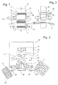
- FIG Fig. 1 and Fig. 2 A device 10 for producing a contoured pleated filter element 1 from a pleated pre-cut filter medium 5 is shown in FIG Fig. 1 and Fig. 2 clarified in different operating states.
- the device 10 comprises a lower counter-holder 12 and a punch 14 axially movable therewith.
- the counter-holder 12 and the punch 14 each have a first surface structure 13 or a second surface structure 15 with a serrated pattern which is adapted to a fold pattern 2 of the filter medium 5 to be trimmed is.
- the filter medium 5 can thus be clamped in a form-accurate manner between the counter-holder 12 and the punch 14, wherein an edge portion 7 of the filter medium 5 projects outwards relative to a first side edge 16 of the counter-holder 12 and a second side edge 17 of the punch 14.
- the first side edge 16 and the second side edge 17 correspond to a contour of the filter element 1 to be produced and are flush with one another.
- the counter-holder 12 and the punch 14 with the clamped filter medium 5 are moved relative to a surrounding annular cutting die 20, the cutting edge rests directly on the two side edges 16, 17.
- By a relative movement of the outwardly projecting edge portion 7 is cut off, wherein the filter element 1 with a defined Edge contour is formed.
- the side edges 16, 17 may have 20 cutting edge edges together with the cutting die to achieve a scissor-like cutting action.
- a rim 4 of the trimmed filter element 1 can be trimmed, in particular flamed.
- the existing of a thermoplastic material filter element 1 is melted along the edge seam 4.
- a layered filter element 1 thus obtains a stabilization and solidification in the edge region.
- the clamped filter element 1 can be moved to an ejection position, wherein the trimmed and trimmed filter element 1 can be removed from the device 10 by axially moving apart of counter-holder 12 and punch 14. This can be done via a discharge device 28 with a laterally movable ejector.
- the discharge device 28 may in the illustration of the Figures 1 and 2 be arranged below the annular cutter and a feed device 26 arranged above it for feeding the filter medium 5 to be contoured.
- FIG. 3 A similar but different device 10 is Fig. 3 refer to.
- a rectangular filter medium 5 as the starting workpiece is placed on a counter holder 12 by a pallet via a feeding device 26, not shown. Subsequently, the filter medium 5 is clamped by axial movement by means of indicated actuating cylinder 22 in a dimensionally accurate manner between the counter-holder 12 and a punch 14 supplied from above.
- the pleated filter medium 5 is, as described above, cropped and provided in the illustrated embodiment with an approximately C-shaped contour 6. Even while the trimmed and contoured filter element 1 is clamped between counter-holder 12 and punch 14, a rim 4 of the filter element 1 is flamed by means of a heater 30, so that the rim 4 is melted and solidified after cooling. For trimming, segments of the heating device 30 can be delivered to the clamped filter element 1 on a holding device 36 linearly to the edge seam 4 in the operating position.
- the trimmed filter element 1 is discharged from the device 10 to a pallet.
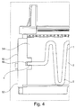
- Fig. 4 shows a filter device 50, in which a according to the invention trimmed and trimmed pleated filter element 1 is installed.
- the pleated filter element 1 has a fold pattern 2 with folds 3 and an outer edge seam 4, which has been melted and stabilized by the method described above.
- the filter element 1 with a defined, stable edge seam 4 can be arranged precisely in a receiving slot 46 on an inner side of a housing 52 of the filter device 50.
- a holding shoulder 54 is formed on the inside of the housing 52, in which the receiving slot 56 is provided.
Landscapes
- Chemical & Material Sciences (AREA)
- Chemical Kinetics & Catalysis (AREA)
- Filtering Materials (AREA)
Description
- Die Erfindung betrifft ein Verfahren zum Herstellen eines konturierten plissierten Filterelementes, bei welchem ein plissiertes Filtermedium mit einem Faltenmuster zwischen einem Gegenhalter und einem Stempel formgenau eingespannt wird, wobei der Gegenhalter und der Stempel eine an das Faltenmuster angepasste Oberflächenstruktur und jeweils einen Seitenrand aufweisen, welcher einer gewünschten Kontur des herzustellenden Filterelementes entspricht, und das eingespannte Filterelement entlang dem Seitenrand aus dem Filtermedium mit der gewünschten Kontur ausgeschnitten wird.
- Die Erfindung betrifft weiterhin eine Vorrichtung zum Herstellen eines konturierten plissierten Filterelementes mit einem Stempel und einem Gegenhalter, welche zum formgenauen Einspannen des plissierten Filtermediums mit einer Oberflächenstruktur versehen sind, welche an ein Faltenmuster des plissierten Filtermediums angepasst ist und jeweils einen Seitenrand aufweist, welcher einer gewünschten Kontur des herzustellenden Filterelementes entspricht.
- Plissierte, mit einem Zickzack-Faltenmuster versehene Filtermedien sind seit Langem bekannt. Diese werden insbesondere in verschiedensten Filtereinrichtungen eingesetzt, bei welchen eine relativ große Filterfläche bei einem geringen Platzbedarf benötigt wird.
- Filtermedien werden üblicherweise als Rollenware oder in rechteckigen Bögen hergestellt, aus welchen dann für die konkrete Filtereinrichtung das benötigte Filterelement mit einer vorgegebenen Kontur ausgeschnitten wird. Aufgrund der Forminstabiment mit einer vorgegebenen Kontur ausgeschnitten wird. Aufgrund der Forminstabilität plissierter Filtermedien sind für ein formgenaues Ausschneiden von Filterelementen besondere Schneidvorrichtungen notwendig.
- Aus der
US 4,976,857 geht eine Vorrichtung und ein Verfahren hervor, bei welchen das plissierte Filtermedium als Ausgangsmaterial in einen gestauchten Zustand gebracht wird, in welchem dann das Filterelement durch ein rotierendes Schneidmesser ausgeschnitten wird. Aufgrund der Rückfederung des gefalteten Filtermateriales nach Wegfall der Stauchkraft treten jedoch Formänderungen und damit Abweichungen in der Randkontur des Filterelementes auf. - Ein gattungsgemäßes Verfahren und eine gattungsgemäße Vorrichtung sind aus der
WO 01/70371 A1 - Ähnliche Verfahren, bei welchen plissierte Filterelemente mit rotierenden, topfförmigen Schneidmessern ausgeschnitten werden, gehen aus der
DE 10 93 188 B oderDE 28 07 546 B1 hervor. - Der Erfindung liegt die Aufgabe zugrunde, ein Verfahren und eine Vorrichtung zum Herstellen eines Filterelementes aus einem plissierten Filtermedium anzugeben, mit welchen unterschiedlichste Konturen formgenau erzeugt werden können.
- Die Erfindung wird zum einen durch ein Verfahren mit dem Merkmal des Anspruchs 1 und zum anderen durch eine Vorrichtung mit den Merkmalen des Anspruchs 8 gelöst. Bevorzugte Ausführungsformen der Erfindung sind in den jeweils abhängigen Ansprüchen angegeben.
- Das erfindungsgemäße Verfahren ist dadurch gekennzeichnet, dass zum Beschneiden eine Schneidmatrize mit einer beliebigen, geschlossenen Ringkontur verwendet wird, welche der gewünschten Kontur des Filterelementes entspricht, und dass als Schneidmatrize ein Stanzmesser verwendet wird, welches zum Beschneiden ausschließlich axial zu dem eingespannten Filtermedium verfahren wird.
- Ein Grundgedanke der Erfindung besteht darin, dass zum Beschneiden eine Schneidmatrize mit einer beliebigen geschlossenen Ringkontur verwendet wird, welche der gewünschten Kontur des Filterelementes entspricht. Grundsätzlich kann eine Zylinderform eingesetzt werden. Es ist nach der Erfindung jedoch nunmehr auch möglich, beliebige, nicht rotationssymmetrische Ringkonturen zu verwenden.
- Nach der Erfindung ist es vorgesehen, dass als Schneidmatrize ein Stanzmesser verwendet wird, welches für einen sauberen Schnitt ausschließlich axial zu dem eingespannten Filtermedium verfahren wird. Es kann ein hohles, ringförmiges Stanzmesser mit einer beliebigen Ringwandkontur eingesetzt werden. Die axiale Schnittrichtung kann insbesondere einer axialen Spannrichtung zwischen Gegenhalter und Stempel entsprechen. Mit derartigen Stanzmessern sind einer Vielfalt der möglichen Konturen des zu bildenden Filterelementes praktisch keine Grenze mehr gesetzt. Eine Schneidkante des Stanzmessers kann in einer Ebene liegen oder dreidimensional gestaltet sein.
- Das erfindungsgemäße Verfahren ist bevorzugt dadurch weitergebildet, dass ein Filtermedium aus einem thermoplastischen Material verwendet wird und das zum Besäumen ein Randsaum des beschnittenen Filterelementes unter Hitzeeinwirkung aufgeschmolzen und verfestigt wird, während das Filterelement zwischen dem Gegenhalter und dem Stempel eingespannt ist. Das Filterelement kann zwischen Gegenhalter und Stempel vollflächig eingespannt sein oder nur in einem Randbereich entlang des Schnittes, um eine unnötige Kompression des Filtermaterials zu vermeiden. Im Stempel kann ein Auswerfer vorgesehen sein, um in einer Auswerfeposition das Plissee auf der Gegenhalterseite zu halten und dann mit dem Auswerfer ausschieben zu können. Durch Anordnung eines Resteniederhalters kann der Stanzschnitt weiter verbessert werden.
- Ein Aspekt der Erfindung besteht daher darin, ein Filtermedium aus einem thermoplastischen Material, insbesondere einem thermoplastischen Kunststoff, zu verwenden. Das Filtermedium als Ausgangsprodukt kann insbesondere ein Gewebe, ein Vlies, ein Gewirk, eine Membran oder eine Kombination aus diesen Materialien sein. Als Kunststoffmaterial kommen insbesondere Polyamid oder ein anderes thermoplastisches Polymer infrage.
- Dabei ist es nach der Erfindung vorgesehen, den beschnittenen Rand des Filterelementes nach dem Beschneiden zu Besäumen, wobei das beschnittene Filterelement zwischen dem Stempel und dem Gegenhalter eingespannt verbleibt. Das Besäumen erfolgt dabei unter Hitzeeinwirkung, etwa durch Heizstrahler oder elektrisch beheizte Kontaktplatten. Durch dieses Aufschmelzen und anschließende Erstarren durch Abkühlen wird die Randkontur verfestigt und stabilisiert. Insbesondere bei einem Gewebe oder bei einem Schichtaufbau kann zudem ein Ausfasern des Randes vermieden werden. Durch ein zeitweises Erweichen des Filterelementes zumindest im Randbereich können sich auch beim Schneidvorgang gebildete Spannungen noch während der Einspannung zwischen Gegenhalter und Stempel abbauen. Hierdurch wird die Gefahr unerwünschter Verformungen nach Entnahme des Filterelementes aus der Schneidvorrichtung weiter vermindert.
- Durch diese insgesamt stabilitätserhöhenden Maßnahmen am Randbereich kann das Filterelement nunmehr durch nahezu beliebige Schneidverfahren aus dem Filtermedium ausgeschnitten werden, ohne dass rotierende Schneidmesser mit relativ hoher Schnittgeschwindigkeit eingesetzt werden müssten.
- Eine bevorzugte Ausführungsform der Erfindung besteht darin, dass zumindest eine Randkante des Gegenhalters oder des Stempels als eine Schneidkante ausgebildet ist. Beim axialen Verfahren der Schneidmatrize relativ zum eingespannten Filtermedium kann so das gegenüberliegende Spannteil, also der Gegenhalter oder der Stempel, mit einer schneidartigen Randkante am Außenumfang der plissierten Fläche versehen sein. Hierdurch bildet sich zwischen dieser Schneidkante und der Schneidkante und konturierten Schneidmatrize eine scherenartige Schnittbewegung aus, welche zu einem besonders sauberen Schnitt und damit einer formgenauen Randkante führt.
- Beim Schneidvorgang kann der Andruck zwischen Gegenhalter und Stempel auf einen ersten hohen Wert eingestellt werden, so dass sich ein entsprechend kleiner Spaltabstand zwischen Gegenhalter und Stempel ergibt. Dies fördert ein sauberes Schnittergebnis.
- Beim anschließenden Besäumen unter Hitzeeinwirkung kann die Andruckkraft auf einen zweiten niedrigeren Wert eingestellt werden, so dass sich auch ein größerer Spaltabstand zwischen Gegenhalter und Stempel einstellt. Dies ist vorteilhaft für das Besäumen.
- Nach einer Ausführungsform der Erfindung ist es vorteilhaft, dass das Filterelement mit einer C-förmigen Kontur ausgebildet wird. Diese Kontur kann bogenförmig oder teilringförmig gestaltet sein. Das Faltenmuster kann in dieser Kontur nahezu beliebig angeordnet sein. Bevorzugt ist, dass die Falten parallel zueinander angeordnet sind und insbesondere sich nach einer Mitten- oder Symmetrieebene der C-förmigen Kontur ausrichten.
- Weiterhin ist es nach der Erfindung vorteilhaft, dass zum Besäumen eine Heizeinrichtung und/oder ein Laser eingesetzt wird. Die Heizeinrichtung kann insbesondere einen oder mehrere Heizstrahler aufweisen. Auch sind elektrisch beheizte Kontaktelemente, induktiv beheizbare Kontaktelemente oder eine Brennereinrichtung mit einer oder mehreren Heizflammen geeignet. Zur Erzeugung der Hitzeeinwirkung kann auch ein Laser verwendet werden. Der Laser kann dabei in seinem Strahl gesteuert sein, um einem nicht linearen Verlauf des Randsaumes folgen zu können. Hierzu kann eine entsprechende Stelleinrichtung oder entsprechende Ablenkelemente an einem Laser vorgesehen und gesteuert sein.
- Ein Besäumen könnte nach einer Variante der Erfindung auch dadurch erreicht werden, dass das eingespannte Filterelement zusammen mit dem Gegenhalter und dem Stempel beim Besäumen gedreht wird. Die Drehung kann dabei relativ zu der Heizeinrichtung erfolgen. Es ist also möglich, dass Gegenhalter und Stempel und/oder die Heizeinrichtung drehend angetrieben sind.
- Weiterhin ist es nach der Erfindung bevorzugt, dass nach dem Besäumen der Gegenhalter und der Stempel axial auseinandergefahren werden und das beschnittene und besäumte Filterelement ausgeworfen wird. Das Auswerfen erfolgt nach einem Abkühlen und Verfestigen des aufgeschmolzenen Randbereiches. Das Auswerfen kann mittels eines Ausstoßers oder einer oder mehrerer Druckluftdüsen erfolgen. Ein Auswerfen kann auch über eine Entnahmeeinrichtung erfolgen, welche etwa einen Entnahmearm mit einer Ansaugeinrichtung aufweist.
- Die erfindungsgemäße Vorrichtung ist dadurch gekennzeichnet, dass eine Schneidmatrize mit einer beliebigen, geschlossenen Ringkontur zum Ausschneiden des eingespannten Filterelementes entlang dem Seitenrand mit der gewünschten Kontur aus dem Filtermedium vorgesehen ist, und dass die Schneidmatrize als Stanzmesser ausgebildet ist, welches zum Beschneiden ausschließlich axial zu dem eingespannten Filtermedium verfahrbar ist.
- Mit der Vorrichtung kann das vorbeschriebene Verfahren durchgeführt und die vorbeschriebenen Vorteile erreicht werden.
- Bei einer Weiterbildung der erfindungsgemäßen Vorrichtung ist es bevorzugt, dass der Gegenhalter und/oder der Stempel in einem Rahmen axial bewegbar gelagert und mittels mindestens eines Stellzylinders axial verfahrbar sind. Durch die Verfahrbarkeit insbesondere von Gegenhalter und Stempel kann das Filterelement von einer Schneidposition zu einer Besäumposition verfahren werden, während es weiter eingespannt bleibt.
- Eine Weiterbildung der erfindungsgemäßen Vorrichtung ist dadurch gekennzeichnet, dass eine Heizeinrichtung und/oder ein Laser vorgesehen sind, mit welchen zum Besäumen des zwischen Gegenhalter und Stempel eingespannten Filterelementes ein Randsaum unter Hitzeeinwirkung aufschmelzbar und verfestigbar ist.
- Dabei besteht eine weitere mögliche Ausführungsform darin, dass eine Dreheinrichtung vorgesehen ist, mit welcher das zwischen dem Gegenhalter und dem Stempel eingespannte Filterelement relativ zu der Heizeinrichtung drehbar ist. Alternativ ist die Heizeinrichtung im Rahmen linear bewegbar, während Gegenhalter und Stempel beim Besäumen feststehen. Die Heizeinrichtung kann in Segmenten über den gesamten Umfang ausgebildet sein.
- Zum Durchführen einer automatischen Fertigung ist es nach der Erfindung bevorzugt, dass eine Zuführeinrichtung zum Zuführen des Filtermediums und eine Abführeinrichtung zum Abführen des beschnittenen Filterelementes vorgesehen sind. Die Zuführeinrichtung und die Abführeinrichtung können insbesondere Greifarme mit geeigneter Saugeinrichtung sein, welche zum Aufnehmen elastischer Filterelemente geeignet sind.
- Mit dieser erfindungsgemäßen Vorrichtung kann insbesondere das zuvor beschriebene Verfahren durchgeführt und die in diesem Zusammenhang beschriebenen Vorteile erreicht werden.
- Die Erfindung wird nachfolgend anhand von bevorzugten Ausführungsbeispielen weiter beschrieben, welche stark schematisiert in den beigefügten Zeichnungen dargestellt sind. In den Zeichnungen zeigen:
- Fig. 1:
- eine stark schematisierte Querschnittsansicht durch eine erfindungsgemäße Vorrichtung;
- Fig. 2:
- eine schematisierte Seiten-Querschnittsansicht der Vorrichtung von
Fig. 1 ; - Fig. 3:
- eine stark schematisierte Prinzipskizze zum Aufbau einer weiteren erfindungsgemäßen Vorrichtung und
- Fig. 4:
- eine schematische Teilquerschnittsansicht durch eine Filtervorrichtung mit einem Filterelement nach der Erfindung.
- Eine Vorrichtung 10 zum Herstellen eines konturierten plissierten Filterelementes 1 aus einem plissierten vorbeschnittenen Filtermedium 5 ist in
Fig. 1 und Fig. 2 in verschiedenen Betriebszuständen verdeutlicht. Die Vorrichtung 10 umfasst einen unteren Gegenhalter 12 und einen dazu axial verfahrbaren Stempel 14. Der Gegenhalter 12 und der Stempel 14 weisen jeweils eine erste Oberflächenstruktur 13 beziehungsweise eine zweite Oberflächenstruktur 15 mit einem Zackenmuster auf, welches an ein Faltenmuster 2 des zu beschneidenden Filtermediums 5 angepasst ist. Das Filtermedium 5 kann so zwischen Gegenhalter 12 und Stempel 14 formgenau eingespannt werden, wobei ein Randabschnitt 7 des Filtermediums 5 gegenüber einem ersten Seitenrand 16 des Gegenhalters 12 und einem zweiten Seitenrand 17 des Stempels 14 nach außen vorsteht. Der erste Seitenrand 16 und der zweite Seitenrand 17 entsprechen einer Kontur des herzustellenden Filterelementes 1 und verlaufen bündig zueinander. Der Gegenhalter 12 und der Stempel 14 mit dem eingespannten Filtermedium 5 werden relativ zu einer umgebenden ringförmigen Schneidmatrize 20 verfahren, dessen Schneidkante unmittelbar an den beiden Seitenrändern 16, 17 anliegt. Durch eine Relativbewegung wird der nach außen vorstehende Randabschnitt 7 abgeschnitten, wobei das Filterelement 1 mit einer definierten Randkontur gebildet wird. Die Seitenränder 16, 17 können dabei zum Erzielen einer scherenartigen Schneidwirkung zusammen mit der Schneidmatrize 20 schneidenartige Randkanten aufweisen. - Durch eine weitere axiale Relativbewegung zu einer Heizeinrichtung 30 kann ein Randsaum 4 des beschnittenen Filterelementes 1 besäumt, insbesondere beflammt werden. Hierbei wird das aus einem thermoplastischen Material bestehende Filterelement 1 entlang des Randsaumes 4 aufgeschmolzen. Insbesondere ein schichtförmig aufgebautes Filterelement 1 erhält so eine Stabilisierung und Verfestigung im Randbereich.
- Anschließend kann das eingespannte Filterelement 1 zu einer Auswurfposition verfahren werden, wobei durch axiales Auseinanderfahren von Gegenhalter 12 und Stempel 14 das beschnittene und besäumte Filterelement 1 aus der Vorrichtung 10 entnommen werden kann. Dies kann über eine Abführeinrichtung 28 mit einem seitlich verfahrbaren Ausstoßer erfolgen. Die Abführeinrichtung 28 kann bei der Darstellung nach den
Figuren 1 und 2 unterhalb der ringförmigen Schneideinrichtung und einer darüber angeordneten Zuführeinrichtung 26 zum Zuführen des zu konturierenden Filtermediums 5 angeordnet sein. - Eine ähnliche, jedoch abweichende Vorrichtung 10 ist
Fig. 3 zu entnehmen. Ein rechteckiges Filtermedium 5 als Ausgangswerkstück wird von einer Palette über eine nicht näher dargestellte Zuführeinrichtung 26 auf einen Gegenhalter 12 aufgelegt. Anschließend wird das Filtermedium 5 durch axiales Verfahren mittels angedeuteter Stellzylinder 22 formgenau zwischen dem Gegenhalter 12 und einem von oben zugeführten Stempel 14 eingespannt. Das plissierte Filtermedium 5 wird, wie oben beschrieben, beschnitten und im gezeigten Ausführungsbeispiel mit einer etwa C-förmigen Kontur 6 versehen. Noch während das beschnittene und konturierte Filterelement 1 zwischen Gegenhalter 12 und Stempel 14 eingespannt ist, wird ein Randsaum 4 des Filterelementes 1 mittels einer Heizeinrichtung 30 beflammt, so dass der Randsaum 4 aufgeschmolzen und nach Abkühlen verfestigt wird. Zum Besäumen können an das eingespannte Filterelement 1 auf einer Haltereinrichtung 36 Segmente der Heizeinrichtung 30 linear an den Randsaum 4 in Betriebsposition zugestellt werden. - Nach Abschluss des Besäumens werden Gegenhalter 12 und Stempel 14 axial auseinander gefahren. Über eine nicht näher dargestellte Abführeinrichtung 28 wird das beschnittene Filterelement 1 aus der Vorrichtung 10 zu einer Palette abgeführt.
-
Fig. 4 zeigt eine Filtervorrichtung 50, in welche ein erfindungsgemäß beschnittenes und besäumtes plissiertes Filterelement 1 eingebaut ist. Das plissierte Filterelement 1 weist ein Faltenmuster 2 mit Falten 3 sowie einen äußeren Randsaum 4 auf, welcher nach dem vorbeschriebenen Verfahren aufgeschmolzen und stabilisiert worden ist. - Aufgrund dieser erfindungsgemäßen Besäumung kann das Filterelement 1 mit einem definierten, stabilen Randsaum 4 formgenau in einen Aufnahmeschlitz 46 an einer Innenseite eines Gehäuses 52 der Filtervorrichtung 50 angeordnet werden. Hierzu ist an der Innenseite des Gehäuses 52 ein Halteabsatz 54 ausgebildet, in welchem der Aufnahmeschlitz 56 vorgesehen ist.
Claims (10)
- Verfahren zum Herstellen eines konturierten plissierten Filterelementes (1), bei welchem- ein plissiertes Filtermedium (5) aus einem thermoplastischen Kunststoff und mit einem Faltenmuster (2) zwischen einem Gegenhalter (12) und einem Stempel (14) formgenau eingespannt wird, wobei der Gegenhalter (12) und der Stempel (14) eine an das Faltenmuster (2) angepasste Oberflächenstruktur (13, 15) und jeweils einen Seitenrand (16, 17) aufweisen, welcher einer gewünschten Kontur (6) des herzustellenden Filterelementes (1) entspricht, und- das eingespannte Filterelement (1) entlang dem Seitenrand (16, 17) aus dem Filtermedium (5) mit der gewünschten Kontur (6) mittels eines Schneidwerkzeugs (20) ausgeschnitten wird,dadurch gekennzeichnet,
dass als Schneidwerkzeug (20) ein Stanzmesser verwendet wird, welches zum Beschneiden ausschließlich axial zu dem eingespannten Filtermedium (5) verfahren wird,
dass ein Stanzmesser mit einer beliebigen geschlossenen Ringkontur verwendet wird, welche der gewünschten Kontur (6) des Filterelementes (1) entspricht, und dass zum Besäumen ein Randsaum (4) des beschnittenen Filterelementes (1) unter Hitzeeinwirkung aufgeschmolzen und verfestigt wird, während das Filterelement (1) zwischen dem Gegenhalter (12) und dem Stempel (14) eingespannt ist. - Verfahren nach Anspruch 1,
dadurch gekennzeichnet,
dass zumindest eine Randkante des Gegenhalters (12) oder des Stempels (14) als eine Schneidkante ausgebildet ist. - Verfahren nach Anspruch 1 oder 2,
dadurch gekennzeichnet,
dass ein Filtermedium (5) aus Polyamid verwendet wird. - Verfahren nach einem der Ansprüche 1 bis 3,
dadurch gekennzeichnet,
dass das Filterelement (1) mit einer C-förmigen Kontur (6) ausgebildet wird. - Verfahren nach einem der Ansprüche 1 bis 4,
dadurch gekennzeichnet,
dass zum Besäumen eine Heizeinrichtung (30) und/oder ein Laser eingesetzt wird. - Verfahren nach einem der Ansprüche 1 bis 5,
dadurch gekennzeichnet,
dass die Heizeinrichtung (30) linear an das eingespannte Filterelement (1) zum Besäumen zugestellt wird. - Verfahren nach einem der Ansprüche 1 bis 6,
dadurch gekennzeichnet,
dass nach dem Besäumen der Gegenhalter (12) und der Stempel (14) axial auseinander gefahren werden und das beschnittene und besäumte Filterelement (1) ausgeworfen wird. - Vorrichtung zum Herstellen eines konturierten plissierten Filterelementes (1), insbesondere nach einem Verfahren nach einem der Ansprüche 1 bis 7,
mit einem Gegenhalter (12) und einem Stempel (14), welche zum formgenauen Einspannen eines plissierten Filtermediums (5) mit einer Oberflächenstruktur (13, 15) versehen sind, welche an ein Faltenmuster (2) des plissierten Filtermediums (5) angepasst sind und jeweils einen Seitenrand (16, 17) aufweisen, welcher einer gewünschten Kontur (6) des herzustellenden Filterelementes (1) entspricht, und
mit einem Schneidwerkzeug (20) zum Ausschneiden des eingespannten Filterelementes (1) entlang dem Seitenrand (16, 17) mit der gewünschten Kontur (6) aus dem Filtermedium (5),
dadurch gekennzeichnet,
dass das Schneidwerkzeug (20) als Stanzmesser ausgebildet ist, welches beim Beschneiden ausschließlich axial zu dem eingespannten Filtermedium (5) verfahrbar ist,
dass das Stanzmesser mit einer beliebigen geschlossenen Ringkontur versehen ist, welche der gewünschten Kontur (6) des Filterelementes (1) entspricht, und dass eine Heizeinrichtung (30) und/oder ein Laser vorgesehen sind, mit welchen zum Besäumen des zwischen Gegenhalter (12) und Stempel (14) eingespannten Filterelementes (1) ein Randsaum (4) unter Hitzeeinwirkung aufschmelzbar und verfestigbar ist. - Vorrichtung nach Anspruch 8,
dadurch gekennzeichnet,
dass der Gegenhalter (12) und/oder der Stempel (14) in einem Rahmen (18) axial bewegbar gelagert und mittels mindestens einem Stellzylinder (22) axial verfahrbar sind. - Vorrichtung nach Anspruch 8 oder 9,
dadurch gekennzeichnet,
dass eine Zuführeinrichtung (26) zum Zuführen des Filtermediums (5) und eine Abführeinrichtung (28) zum Abführen des beschnittenen Filterelementes (1) vorgesehen sind.
Applications Claiming Priority (2)
| Application Number | Priority Date | Filing Date | Title |
|---|---|---|---|
| DE102012022769.8A DE102012022769B4 (de) | 2012-11-22 | 2012-11-22 | Verfahren und vorrichtung zum herstellen eines konturierten plissierten filterelementes |
| PCT/EP2013/069686 WO2014079606A1 (de) | 2012-11-22 | 2013-09-23 | Verfahren und vorrichtung zum herstellen eines konturierten plissierten filterelementes |
Publications (2)
| Publication Number | Publication Date |
|---|---|
| EP2922610A1 EP2922610A1 (de) | 2015-09-30 |
| EP2922610B1 true EP2922610B1 (de) | 2016-09-21 |
Family
ID=49448107
Family Applications (1)
| Application Number | Title | Priority Date | Filing Date |
|---|---|---|---|
| EP13779751.0A Active EP2922610B1 (de) | 2012-11-22 | 2013-09-23 | Verfahren und vorrichtung zum herstellen eines konturierten plissierten filterelementes |
Country Status (4)
| Country | Link |
|---|---|
| EP (1) | EP2922610B1 (de) |
| DE (1) | DE102012022769B4 (de) |
| ES (1) | ES2607631T3 (de) |
| WO (1) | WO2014079606A1 (de) |
Families Citing this family (2)
| Publication number | Priority date | Publication date | Assignee | Title |
|---|---|---|---|---|
| EP3777989B1 (de) * | 2015-08-17 | 2025-06-04 | Parker-Hannifin Corporation | Filtermedienpacks, verfahren zur herstellung und filtermedienpressen |
| US11123946B2 (en) * | 2019-02-07 | 2021-09-21 | K&N Engineering, Inc. | Pleated filter preparation system |
Family Cites Families (4)
| Publication number | Priority date | Publication date | Assignee | Title |
|---|---|---|---|---|
| BE561717A (de) * | 1956-10-24 | |||
| DE2807546C2 (de) * | 1978-02-20 | 1984-02-16 | Auergesellschaft Gmbh, 1000 Berlin | Kreisscheibenförmiges Filterelement aus parallel gefaltetem, bahnenartigem Filtermaterial und Verfahren zu dessen Herstellung |
| US4976857A (en) | 1989-05-03 | 1990-12-11 | Newport Filters, Inc. | Filter element and fabrication methodology |
| EP1136112A1 (de) * | 2000-03-23 | 2001-09-26 | 3M Innovative Properties Company | Verfahren zur Herstellung eines im wesentlichen zylindrischen gefalteten Filterelements |
-
2012
- 2012-11-22 DE DE102012022769.8A patent/DE102012022769B4/de not_active Expired - Fee Related
-
2013
- 2013-09-23 ES ES13779751.0T patent/ES2607631T3/es active Active
- 2013-09-23 WO PCT/EP2013/069686 patent/WO2014079606A1/de not_active Ceased
- 2013-09-23 EP EP13779751.0A patent/EP2922610B1/de active Active
Non-Patent Citations (1)
| Title |
|---|
| None * |
Also Published As
| Publication number | Publication date |
|---|---|
| DE102012022769B4 (de) | 2017-08-31 |
| WO2014079606A1 (de) | 2014-05-30 |
| EP2922610A1 (de) | 2015-09-30 |
| ES2607631T3 (es) | 2017-04-03 |
| DE102012022769A1 (de) | 2014-05-22 |
Similar Documents
| Publication | Publication Date | Title |
|---|---|---|
| DE2829718C2 (de) | Vakuumtiefziehvorrichtung zum Herstellen von napfförmigen Gegenständen durch Saugunterdruck aus einer Bahn aus thermoplastischem Kunststoff | |
| EP1340584B1 (de) | Maschine zum thermischen Schneiden von Werkstücken insbesondere mittels Laser | |
| WO2017202767A1 (de) | Maschine zum trennenden bearbeiten eines plattenförmigen werkstücks und verfahren zum ausdrücken eines freigetrennten werkstückteils | |
| EP2556920B1 (de) | Vorrichtung zum Schärfen von Messern eines Messerrings für einen Messerringzerspaner | |
| DE3045095A1 (de) | Vorrichtung zum abstreifen von abfallstuecken von zuschnitten | |
| DE102010011735B3 (de) | Anordnung zum Ablängen von Nagelrohlingen von einem intermittierend zugeführten Draht | |
| DE102018215545B4 (de) | Verfahren zum Herstellen eines pressgehärteten Blechformteils und Presshärtewerkzeug | |
| DE102008008112A1 (de) | Vorrichtung zum Stanzen | |
| EP3515622B1 (de) | Werkzeug und werkzeugmaschine sowie verfahren zum schneiden und/oder umformen von plattenförmigen werkstücken | |
| DE102012022769B4 (de) | Verfahren und vorrichtung zum herstellen eines konturierten plissierten filterelementes | |
| DE2555697B2 (de) | Verfahren zum Herstellen von Doppelkontaktnieten | |
| DE2825631A1 (de) | Verfahren und vorrichtungen zum trennen von am umriss geschweissten, d.h. verschweissten oder ausgeschweissten werkstuecken aus thermoplastischem material von der sie noch umgebenden, den abfall bildenden materialbahn oder folie | |
| DE1914787B2 (de) | Vorrichtung mit einer oberen und unteren PreBplatte | |
| EP2093030B1 (de) | Verfahren und Vorrichtung zur Entfernung von Stanzabfällen | |
| DE2328368B2 (de) | Thermoformvorrichtung zum herstellen von formlingen grosser tiefe aus einem relativ dicken kunststoffband | |
| DE102014210867B4 (de) | Platinenschneidwerkzeug mit mehreren Schneidstationen | |
| DE3932571C1 (de) | ||
| DE1030669B (de) | Vorrichtung zum kontinuierlichen Herstellen von Faltbehaeltern | |
| DE102016120139A1 (de) | Verfahren, Werkzeugmaschine und Schlitzwerkzeug zum mehrhubig fortschreitenden Schlitzen von plattenförmigen Werkstücken | |
| DE3336660C1 (de) | Vorrichtung zum Herstellen von Löchern in flächenhaftem Material | |
| DE102004051143B4 (de) | Falzvorrichtung für eine Rollen-Rotationsdruckmaschine | |
| EP1914048A2 (de) | Verfahren und Vorrichtung zum Stanzen eines Filtermaterials | |
| DE2733626A1 (de) | Schneideinrichtung fuer verpackungsmaschinen | |
| DD225331A1 (de) | Vorrichtung und verfahren zum formen von buestenteilen | |
| DE336426C (de) | Maschine zum Herstellen von Hohlkoerpern aus Zelluloid oder aehnlichen Stoffen |
Legal Events
| Date | Code | Title | Description |
|---|---|---|---|
| PUAI | Public reference made under article 153(3) epc to a published international application that has entered the european phase |
Free format text: ORIGINAL CODE: 0009012 |
|
| 17P | Request for examination filed |
Effective date: 20150331 |
|
| AK | Designated contracting states |
Kind code of ref document: A1 Designated state(s): AL AT BE BG CH CY CZ DE DK EE ES FI FR GB GR HR HU IE IS IT LI LT LU LV MC MK MT NL NO PL PT RO RS SE SI SK SM TR |
|
| AX | Request for extension of the european patent |
Extension state: BA ME |
|
| DAX | Request for extension of the european patent (deleted) | ||
| GRAP | Despatch of communication of intention to grant a patent |
Free format text: ORIGINAL CODE: EPIDOSNIGR1 |
|
| INTG | Intention to grant announced |
Effective date: 20160408 |
|
| GRAJ | Information related to disapproval of communication of intention to grant by the applicant or resumption of examination proceedings by the epo deleted |
Free format text: ORIGINAL CODE: EPIDOSDIGR1 |
|
| GRAJ | Information related to disapproval of communication of intention to grant by the applicant or resumption of examination proceedings by the epo deleted |
Free format text: ORIGINAL CODE: EPIDOSDIGR1 |
|
| GRAP | Despatch of communication of intention to grant a patent |
Free format text: ORIGINAL CODE: EPIDOSNIGR1 |
|
| GRAJ | Information related to disapproval of communication of intention to grant by the applicant or resumption of examination proceedings by the epo deleted |
Free format text: ORIGINAL CODE: EPIDOSDIGR1 |
|
| GRAR | Information related to intention to grant a patent recorded |
Free format text: ORIGINAL CODE: EPIDOSNIGR71 |
|
| GRAS | Grant fee paid |
Free format text: ORIGINAL CODE: EPIDOSNIGR3 |
|
| GRAA | (expected) grant |
Free format text: ORIGINAL CODE: 0009210 |
|
| INTC | Intention to grant announced (deleted) | ||
| INTG | Intention to grant announced |
Effective date: 20160811 |
|
| AK | Designated contracting states |
Kind code of ref document: B1 Designated state(s): AL AT BE BG CH CY CZ DE DK EE ES FI FR GB GR HR HU IE IS IT LI LT LU LV MC MK MT NL NO PL PT RO RS SE SI SK SM TR |
|
| REG | Reference to a national code |
Ref country code: GB Ref legal event code: FG4D Free format text: NOT ENGLISH |
|
| REG | Reference to a national code |
Ref country code: CH Ref legal event code: EP |
|
| REG | Reference to a national code |
Ref country code: AT Ref legal event code: REF Ref document number: 830592 Country of ref document: AT Kind code of ref document: T Effective date: 20161015 |
|
| REG | Reference to a national code |
Ref country code: IE Ref legal event code: FG4D Free format text: LANGUAGE OF EP DOCUMENT: GERMAN |
|
| REG | Reference to a national code |
Ref country code: DE Ref legal event code: R096 Ref document number: 502013004705 Country of ref document: DE |
|
| REG | Reference to a national code |
Ref country code: LT Ref legal event code: MG4D Ref country code: NL Ref legal event code: MP Effective date: 20160921 |
|
| PG25 | Lapsed in a contracting state [announced via postgrant information from national office to epo] |
Ref country code: LT Free format text: LAPSE BECAUSE OF FAILURE TO SUBMIT A TRANSLATION OF THE DESCRIPTION OR TO PAY THE FEE WITHIN THE PRESCRIBED TIME-LIMIT Effective date: 20160921 Ref country code: NO Free format text: LAPSE BECAUSE OF FAILURE TO SUBMIT A TRANSLATION OF THE DESCRIPTION OR TO PAY THE FEE WITHIN THE PRESCRIBED TIME-LIMIT Effective date: 20161221 Ref country code: RS Free format text: LAPSE BECAUSE OF FAILURE TO SUBMIT A TRANSLATION OF THE DESCRIPTION OR TO PAY THE FEE WITHIN THE PRESCRIBED TIME-LIMIT Effective date: 20160921 Ref country code: FI Free format text: LAPSE BECAUSE OF FAILURE TO SUBMIT A TRANSLATION OF THE DESCRIPTION OR TO PAY THE FEE WITHIN THE PRESCRIBED TIME-LIMIT Effective date: 20160921 |
|
| PG25 | Lapsed in a contracting state [announced via postgrant information from national office to epo] |
Ref country code: GR Free format text: LAPSE BECAUSE OF FAILURE TO SUBMIT A TRANSLATION OF THE DESCRIPTION OR TO PAY THE FEE WITHIN THE PRESCRIBED TIME-LIMIT Effective date: 20161222 Ref country code: LV Free format text: LAPSE BECAUSE OF FAILURE TO SUBMIT A TRANSLATION OF THE DESCRIPTION OR TO PAY THE FEE WITHIN THE PRESCRIBED TIME-LIMIT Effective date: 20160921 Ref country code: NL Free format text: LAPSE BECAUSE OF FAILURE TO SUBMIT A TRANSLATION OF THE DESCRIPTION OR TO PAY THE FEE WITHIN THE PRESCRIBED TIME-LIMIT Effective date: 20160921 Ref country code: BE Free format text: LAPSE BECAUSE OF NON-PAYMENT OF DUE FEES Effective date: 20160930 Ref country code: SE Free format text: LAPSE BECAUSE OF FAILURE TO SUBMIT A TRANSLATION OF THE DESCRIPTION OR TO PAY THE FEE WITHIN THE PRESCRIBED TIME-LIMIT Effective date: 20160921 |
|
| PG25 | Lapsed in a contracting state [announced via postgrant information from national office to epo] |
Ref country code: RO Free format text: LAPSE BECAUSE OF FAILURE TO SUBMIT A TRANSLATION OF THE DESCRIPTION OR TO PAY THE FEE WITHIN THE PRESCRIBED TIME-LIMIT Effective date: 20160921 Ref country code: EE Free format text: LAPSE BECAUSE OF FAILURE TO SUBMIT A TRANSLATION OF THE DESCRIPTION OR TO PAY THE FEE WITHIN THE PRESCRIBED TIME-LIMIT Effective date: 20160921 |
|
| REG | Reference to a national code |
Ref country code: CH Ref legal event code: PL |
|
| PG25 | Lapsed in a contracting state [announced via postgrant information from national office to epo] |
Ref country code: SM Free format text: LAPSE BECAUSE OF FAILURE TO SUBMIT A TRANSLATION OF THE DESCRIPTION OR TO PAY THE FEE WITHIN THE PRESCRIBED TIME-LIMIT Effective date: 20160921 Ref country code: BG Free format text: LAPSE BECAUSE OF FAILURE TO SUBMIT A TRANSLATION OF THE DESCRIPTION OR TO PAY THE FEE WITHIN THE PRESCRIBED TIME-LIMIT Effective date: 20161221 Ref country code: PL Free format text: LAPSE BECAUSE OF FAILURE TO SUBMIT A TRANSLATION OF THE DESCRIPTION OR TO PAY THE FEE WITHIN THE PRESCRIBED TIME-LIMIT Effective date: 20160921 Ref country code: SK Free format text: LAPSE BECAUSE OF FAILURE TO SUBMIT A TRANSLATION OF THE DESCRIPTION OR TO PAY THE FEE WITHIN THE PRESCRIBED TIME-LIMIT Effective date: 20160921 Ref country code: PT Free format text: LAPSE BECAUSE OF FAILURE TO SUBMIT A TRANSLATION OF THE DESCRIPTION OR TO PAY THE FEE WITHIN THE PRESCRIBED TIME-LIMIT Effective date: 20170123 Ref country code: IS Free format text: LAPSE BECAUSE OF FAILURE TO SUBMIT A TRANSLATION OF THE DESCRIPTION OR TO PAY THE FEE WITHIN THE PRESCRIBED TIME-LIMIT Effective date: 20170121 |
|
| REG | Reference to a national code |
Ref country code: DE Ref legal event code: R097 Ref document number: 502013004705 Country of ref document: DE |
|
| REG | Reference to a national code |
Ref country code: IE Ref legal event code: MM4A |
|
| PLBE | No opposition filed within time limit |
Free format text: ORIGINAL CODE: 0009261 |
|
| STAA | Information on the status of an ep patent application or granted ep patent |
Free format text: STATUS: NO OPPOSITION FILED WITHIN TIME LIMIT |
|
| PG25 | Lapsed in a contracting state [announced via postgrant information from national office to epo] |
Ref country code: DK Free format text: LAPSE BECAUSE OF FAILURE TO SUBMIT A TRANSLATION OF THE DESCRIPTION OR TO PAY THE FEE WITHIN THE PRESCRIBED TIME-LIMIT Effective date: 20160921 Ref country code: LI Free format text: LAPSE BECAUSE OF NON-PAYMENT OF DUE FEES Effective date: 20160930 Ref country code: IE Free format text: LAPSE BECAUSE OF NON-PAYMENT OF DUE FEES Effective date: 20160923 Ref country code: CH Free format text: LAPSE BECAUSE OF NON-PAYMENT OF DUE FEES Effective date: 20160930 |
|
| REG | Reference to a national code |
Ref country code: FR Ref legal event code: ST Effective date: 20170726 |
|
| 26N | No opposition filed |
Effective date: 20170622 |
|
| PG25 | Lapsed in a contracting state [announced via postgrant information from national office to epo] |
Ref country code: LU Free format text: LAPSE BECAUSE OF NON-PAYMENT OF DUE FEES Effective date: 20160923 |
|
| PG25 | Lapsed in a contracting state [announced via postgrant information from national office to epo] |
Ref country code: FR Free format text: LAPSE BECAUSE OF NON-PAYMENT OF DUE FEES Effective date: 20161121 |
|
| REG | Reference to a national code |
Ref country code: BE Ref legal event code: MM Effective date: 20160930 |
|
| PG25 | Lapsed in a contracting state [announced via postgrant information from national office to epo] |
Ref country code: SI Free format text: LAPSE BECAUSE OF FAILURE TO SUBMIT A TRANSLATION OF THE DESCRIPTION OR TO PAY THE FEE WITHIN THE PRESCRIBED TIME-LIMIT Effective date: 20160921 |
|
| REG | Reference to a national code |
Ref country code: DE Ref legal event code: R082 Ref document number: 502013004705 Country of ref document: DE Representative=s name: WUNDERLICH & HEIM PATENTANWAELTE PARTNERSCHAFT, DE |
|
| GBPC | Gb: european patent ceased through non-payment of renewal fee |
Effective date: 20170923 |
|
| PG25 | Lapsed in a contracting state [announced via postgrant information from national office to epo] |
Ref country code: HU Free format text: LAPSE BECAUSE OF FAILURE TO SUBMIT A TRANSLATION OF THE DESCRIPTION OR TO PAY THE FEE WITHIN THE PRESCRIBED TIME-LIMIT; INVALID AB INITIO Effective date: 20130923 |
|
| PG25 | Lapsed in a contracting state [announced via postgrant information from national office to epo] |
Ref country code: CY Free format text: LAPSE BECAUSE OF FAILURE TO SUBMIT A TRANSLATION OF THE DESCRIPTION OR TO PAY THE FEE WITHIN THE PRESCRIBED TIME-LIMIT Effective date: 20160921 Ref country code: MK Free format text: LAPSE BECAUSE OF FAILURE TO SUBMIT A TRANSLATION OF THE DESCRIPTION OR TO PAY THE FEE WITHIN THE PRESCRIBED TIME-LIMIT Effective date: 20160921 Ref country code: MC Free format text: LAPSE BECAUSE OF FAILURE TO SUBMIT A TRANSLATION OF THE DESCRIPTION OR TO PAY THE FEE WITHIN THE PRESCRIBED TIME-LIMIT Effective date: 20160921 Ref country code: HR Free format text: LAPSE BECAUSE OF FAILURE TO SUBMIT A TRANSLATION OF THE DESCRIPTION OR TO PAY THE FEE WITHIN THE PRESCRIBED TIME-LIMIT Effective date: 20160921 Ref country code: MT Free format text: LAPSE BECAUSE OF FAILURE TO SUBMIT A TRANSLATION OF THE DESCRIPTION OR TO PAY THE FEE WITHIN THE PRESCRIBED TIME-LIMIT Effective date: 20160921 |
|
| PG25 | Lapsed in a contracting state [announced via postgrant information from national office to epo] |
Ref country code: GB Free format text: LAPSE BECAUSE OF NON-PAYMENT OF DUE FEES Effective date: 20170923 |
|
| PG25 | Lapsed in a contracting state [announced via postgrant information from national office to epo] |
Ref country code: AL Free format text: LAPSE BECAUSE OF FAILURE TO SUBMIT A TRANSLATION OF THE DESCRIPTION OR TO PAY THE FEE WITHIN THE PRESCRIBED TIME-LIMIT Effective date: 20160921 Ref country code: TR Free format text: LAPSE BECAUSE OF FAILURE TO SUBMIT A TRANSLATION OF THE DESCRIPTION OR TO PAY THE FEE WITHIN THE PRESCRIBED TIME-LIMIT Effective date: 20160921 |
|
| REG | Reference to a national code |
Ref country code: AT Ref legal event code: MM01 Ref document number: 830592 Country of ref document: AT Kind code of ref document: T Effective date: 20180923 |
|
| PG25 | Lapsed in a contracting state [announced via postgrant information from national office to epo] |
Ref country code: AT Free format text: LAPSE BECAUSE OF NON-PAYMENT OF DUE FEES Effective date: 20180923 |
|
| PGFP | Annual fee paid to national office [announced via postgrant information from national office to epo] |
Ref country code: CZ Payment date: 20220913 Year of fee payment: 10 |
|
| PGFP | Annual fee paid to national office [announced via postgrant information from national office to epo] |
Ref country code: IT Payment date: 20220930 Year of fee payment: 10 Ref country code: ES Payment date: 20221018 Year of fee payment: 10 |
|
| P01 | Opt-out of the competence of the unified patent court (upc) registered |
Effective date: 20230505 |
|
| PG25 | Lapsed in a contracting state [announced via postgrant information from national office to epo] |
Ref country code: CZ Free format text: LAPSE BECAUSE OF NON-PAYMENT OF DUE FEES Effective date: 20230923 |
|
| PGFP | Annual fee paid to national office [announced via postgrant information from national office to epo] |
Ref country code: DE Payment date: 20240920 Year of fee payment: 12 |
|
| REG | Reference to a national code |
Ref country code: ES Ref legal event code: FD2A Effective date: 20241106 |
|
| PG25 | Lapsed in a contracting state [announced via postgrant information from national office to epo] |
Ref country code: IT Free format text: LAPSE BECAUSE OF NON-PAYMENT OF DUE FEES Effective date: 20230923 |
|
| PG25 | Lapsed in a contracting state [announced via postgrant information from national office to epo] |
Ref country code: IT Free format text: LAPSE BECAUSE OF NON-PAYMENT OF DUE FEES Effective date: 20230923 |
|
| PG25 | Lapsed in a contracting state [announced via postgrant information from national office to epo] |
Ref country code: ES Free format text: LAPSE BECAUSE OF NON-PAYMENT OF DUE FEES Effective date: 20230924 |
|
| PG25 | Lapsed in a contracting state [announced via postgrant information from national office to epo] |
Ref country code: ES Free format text: LAPSE BECAUSE OF NON-PAYMENT OF DUE FEES Effective date: 20230924 |