EP2921678B1 - Brennkraftmaschine, insbesondere Gasmotor, für ein Kraftfahrzeug - Google Patents
Brennkraftmaschine, insbesondere Gasmotor, für ein Kraftfahrzeug Download PDFInfo
- Publication number
- EP2921678B1 EP2921678B1 EP15000122.0A EP15000122A EP2921678B1 EP 2921678 B1 EP2921678 B1 EP 2921678B1 EP 15000122 A EP15000122 A EP 15000122A EP 2921678 B1 EP2921678 B1 EP 2921678B1
- Authority
- EP
- European Patent Office
- Prior art keywords
- mass flow
- air mass
- intercooler
- throttle valve
- egr
- Prior art date
- Legal status (The legal status is an assumption and is not a legal conclusion. Google has not performed a legal analysis and makes no representation as to the accuracy of the status listed.)
- Active
Links
Images

Classifications
-
- F—MECHANICAL ENGINEERING; LIGHTING; HEATING; WEAPONS; BLASTING
- F02—COMBUSTION ENGINES; HOT-GAS OR COMBUSTION-PRODUCT ENGINE PLANTS
- F02B—INTERNAL-COMBUSTION PISTON ENGINES; COMBUSTION ENGINES IN GENERAL
- F02B29/00—Engines characterised by provision for charging or scavenging not provided for in groups F02B25/00, F02B27/00 or F02B33/00 - F02B39/00; Details thereof
- F02B29/04—Cooling of air intake supply
- F02B29/0406—Layout of the intake air cooling or coolant circuit
-
- F—MECHANICAL ENGINEERING; LIGHTING; HEATING; WEAPONS; BLASTING
- F02—COMBUSTION ENGINES; HOT-GAS OR COMBUSTION-PRODUCT ENGINE PLANTS
- F02B—INTERNAL-COMBUSTION PISTON ENGINES; COMBUSTION ENGINES IN GENERAL
- F02B29/00—Engines characterised by provision for charging or scavenging not provided for in groups F02B25/00, F02B27/00 or F02B33/00 - F02B39/00; Details thereof
- F02B29/04—Cooling of air intake supply
- F02B29/0406—Layout of the intake air cooling or coolant circuit
- F02B29/0425—Air cooled heat exchangers
-
- F—MECHANICAL ENGINEERING; LIGHTING; HEATING; WEAPONS; BLASTING
- F02—COMBUSTION ENGINES; HOT-GAS OR COMBUSTION-PRODUCT ENGINE PLANTS
- F02D—CONTROLLING COMBUSTION ENGINES
- F02D19/00—Controlling engines characterised by their use of non-liquid fuels, pluralities of fuels, or non-fuel substances added to the combustible mixtures
- F02D19/02—Controlling engines characterised by their use of non-liquid fuels, pluralities of fuels, or non-fuel substances added to the combustible mixtures peculiar to engines working with gaseous fuels
- F02D19/026—Measuring or estimating parameters related to the fuel supply system
- F02D19/027—Determining the fuel pressure, temperature or volume flow, the fuel tank fill level or a valve position
-
- F—MECHANICAL ENGINEERING; LIGHTING; HEATING; WEAPONS; BLASTING
- F02—COMBUSTION ENGINES; HOT-GAS OR COMBUSTION-PRODUCT ENGINE PLANTS
- F02D—CONTROLLING COMBUSTION ENGINES
- F02D41/00—Electrical control of supply of combustible mixture or its constituents
- F02D41/0025—Controlling engines characterised by use of non-liquid fuels, pluralities of fuels, or non-fuel substances added to the combustible mixtures
- F02D41/0027—Controlling engines characterised by use of non-liquid fuels, pluralities of fuels, or non-fuel substances added to the combustible mixtures the fuel being gaseous
-
- F—MECHANICAL ENGINEERING; LIGHTING; HEATING; WEAPONS; BLASTING
- F02—COMBUSTION ENGINES; HOT-GAS OR COMBUSTION-PRODUCT ENGINE PLANTS
- F02D—CONTROLLING COMBUSTION ENGINES
- F02D41/00—Electrical control of supply of combustible mixture or its constituents
- F02D41/02—Circuit arrangements for generating control signals
- F02D41/18—Circuit arrangements for generating control signals by measuring intake air flow
-
- F—MECHANICAL ENGINEERING; LIGHTING; HEATING; WEAPONS; BLASTING
- F02—COMBUSTION ENGINES; HOT-GAS OR COMBUSTION-PRODUCT ENGINE PLANTS
- F02M—SUPPLYING COMBUSTION ENGINES IN GENERAL WITH COMBUSTIBLE MIXTURES OR CONSTITUENTS THEREOF
- F02M21/00—Apparatus for supplying engines with non-liquid fuels, e.g. gaseous fuels stored in liquid form
- F02M21/02—Apparatus for supplying engines with non-liquid fuels, e.g. gaseous fuels stored in liquid form for gaseous fuels
- F02M21/0203—Apparatus for supplying engines with non-liquid fuels, e.g. gaseous fuels stored in liquid form for gaseous fuels characterised by the type of gaseous fuel
- F02M21/0215—Mixtures of gaseous fuels; Natural gas; Biogas; Mine gas; Landfill gas
-
- F—MECHANICAL ENGINEERING; LIGHTING; HEATING; WEAPONS; BLASTING
- F02—COMBUSTION ENGINES; HOT-GAS OR COMBUSTION-PRODUCT ENGINE PLANTS
- F02M—SUPPLYING COMBUSTION ENGINES IN GENERAL WITH COMBUSTIBLE MIXTURES OR CONSTITUENTS THEREOF
- F02M21/00—Apparatus for supplying engines with non-liquid fuels, e.g. gaseous fuels stored in liquid form
- F02M21/02—Apparatus for supplying engines with non-liquid fuels, e.g. gaseous fuels stored in liquid form for gaseous fuels
- F02M21/0218—Details on the gaseous fuel supply system, e.g. tanks, valves, pipes, pumps, rails, injectors or mixers
- F02M21/0248—Injectors
- F02M21/0278—Port fuel injectors for single or multipoint injection into the air intake system
-
- F—MECHANICAL ENGINEERING; LIGHTING; HEATING; WEAPONS; BLASTING
- F02—COMBUSTION ENGINES; HOT-GAS OR COMBUSTION-PRODUCT ENGINE PLANTS
- F02M—SUPPLYING COMBUSTION ENGINES IN GENERAL WITH COMBUSTIBLE MIXTURES OR CONSTITUENTS THEREOF
- F02M21/00—Apparatus for supplying engines with non-liquid fuels, e.g. gaseous fuels stored in liquid form
- F02M21/02—Apparatus for supplying engines with non-liquid fuels, e.g. gaseous fuels stored in liquid form for gaseous fuels
- F02M21/0218—Details on the gaseous fuel supply system, e.g. tanks, valves, pipes, pumps, rails, injectors or mixers
- F02M21/0284—Arrangement of multiple injectors or fuel-air mixers per combustion chamber
-
- F—MECHANICAL ENGINEERING; LIGHTING; HEATING; WEAPONS; BLASTING
- F02—COMBUSTION ENGINES; HOT-GAS OR COMBUSTION-PRODUCT ENGINE PLANTS
- F02M—SUPPLYING COMBUSTION ENGINES IN GENERAL WITH COMBUSTIBLE MIXTURES OR CONSTITUENTS THEREOF
- F02M21/00—Apparatus for supplying engines with non-liquid fuels, e.g. gaseous fuels stored in liquid form
- F02M21/02—Apparatus for supplying engines with non-liquid fuels, e.g. gaseous fuels stored in liquid form for gaseous fuels
- F02M21/04—Gas-air mixing apparatus
-
- F—MECHANICAL ENGINEERING; LIGHTING; HEATING; WEAPONS; BLASTING
- F02—COMBUSTION ENGINES; HOT-GAS OR COMBUSTION-PRODUCT ENGINE PLANTS
- F02M—SUPPLYING COMBUSTION ENGINES IN GENERAL WITH COMBUSTIBLE MIXTURES OR CONSTITUENTS THEREOF
- F02M21/00—Apparatus for supplying engines with non-liquid fuels, e.g. gaseous fuels stored in liquid form
- F02M21/02—Apparatus for supplying engines with non-liquid fuels, e.g. gaseous fuels stored in liquid form for gaseous fuels
- F02M21/04—Gas-air mixing apparatus
- F02M21/042—Mixer comprising a plurality of bores or flow passages
-
- F—MECHANICAL ENGINEERING; LIGHTING; HEATING; WEAPONS; BLASTING
- F02—COMBUSTION ENGINES; HOT-GAS OR COMBUSTION-PRODUCT ENGINE PLANTS
- F02M—SUPPLYING COMBUSTION ENGINES IN GENERAL WITH COMBUSTIBLE MIXTURES OR CONSTITUENTS THEREOF
- F02M35/00—Combustion-air cleaners, air intakes, intake silencers, or induction systems specially adapted for, or arranged on, internal-combustion engines
- F02M35/10—Air intakes; Induction systems
- F02M35/10373—Sensors for intake systems
- F02M35/1038—Sensors for intake systems for temperature or pressure
-
- F—MECHANICAL ENGINEERING; LIGHTING; HEATING; WEAPONS; BLASTING
- F02—COMBUSTION ENGINES; HOT-GAS OR COMBUSTION-PRODUCT ENGINE PLANTS
- F02D—CONTROLLING COMBUSTION ENGINES
- F02D2200/00—Input parameters for engine control
- F02D2200/02—Input parameters for engine control the parameters being related to the engine
- F02D2200/04—Engine intake system parameters
- F02D2200/0402—Engine intake system parameters the parameter being determined by using a model of the engine intake or its components
-
- F—MECHANICAL ENGINEERING; LIGHTING; HEATING; WEAPONS; BLASTING
- F02—COMBUSTION ENGINES; HOT-GAS OR COMBUSTION-PRODUCT ENGINE PLANTS
- F02D—CONTROLLING COMBUSTION ENGINES
- F02D2200/00—Input parameters for engine control
- F02D2200/02—Input parameters for engine control the parameters being related to the engine
- F02D2200/04—Engine intake system parameters
- F02D2200/0404—Throttle position
-
- F—MECHANICAL ENGINEERING; LIGHTING; HEATING; WEAPONS; BLASTING
- F02—COMBUSTION ENGINES; HOT-GAS OR COMBUSTION-PRODUCT ENGINE PLANTS
- F02D—CONTROLLING COMBUSTION ENGINES
- F02D2200/00—Input parameters for engine control
- F02D2200/02—Input parameters for engine control the parameters being related to the engine
- F02D2200/04—Engine intake system parameters
- F02D2200/0406—Intake manifold pressure
-
- F—MECHANICAL ENGINEERING; LIGHTING; HEATING; WEAPONS; BLASTING
- F02—COMBUSTION ENGINES; HOT-GAS OR COMBUSTION-PRODUCT ENGINE PLANTS
- F02D—CONTROLLING COMBUSTION ENGINES
- F02D41/00—Electrical control of supply of combustible mixture or its constituents
- F02D41/0025—Controlling engines characterised by use of non-liquid fuels, pluralities of fuels, or non-fuel substances added to the combustible mixtures
- F02D41/0047—Controlling exhaust gas recirculation [EGR]
-
- F—MECHANICAL ENGINEERING; LIGHTING; HEATING; WEAPONS; BLASTING
- F02—COMBUSTION ENGINES; HOT-GAS OR COMBUSTION-PRODUCT ENGINE PLANTS
- F02M—SUPPLYING COMBUSTION ENGINES IN GENERAL WITH COMBUSTIBLE MIXTURES OR CONSTITUENTS THEREOF
- F02M26/00—Engine-pertinent apparatus for adding exhaust gases to combustion-air, main fuel or fuel-air mixture, e.g. by exhaust gas recirculation [EGR] systems
- F02M26/02—EGR systems specially adapted for supercharged engines
- F02M26/04—EGR systems specially adapted for supercharged engines with a single turbocharger
- F02M26/05—High pressure loops, i.e. wherein recirculated exhaust gas is taken out from the exhaust system upstream of the turbine and reintroduced into the intake system downstream of the compressor
-
- F—MECHANICAL ENGINEERING; LIGHTING; HEATING; WEAPONS; BLASTING
- F02—COMBUSTION ENGINES; HOT-GAS OR COMBUSTION-PRODUCT ENGINE PLANTS
- F02M—SUPPLYING COMBUSTION ENGINES IN GENERAL WITH COMBUSTIBLE MIXTURES OR CONSTITUENTS THEREOF
- F02M26/00—Engine-pertinent apparatus for adding exhaust gases to combustion-air, main fuel or fuel-air mixture, e.g. by exhaust gas recirculation [EGR] systems
- F02M26/13—Arrangement or layout of EGR passages, e.g. in relation to specific engine parts or for incorporation of accessories
- F02M26/22—Arrangement or layout of EGR passages, e.g. in relation to specific engine parts or for incorporation of accessories with coolers in the recirculation passage
- F02M26/23—Layout, e.g. schematics
-
- Y—GENERAL TAGGING OF NEW TECHNOLOGICAL DEVELOPMENTS; GENERAL TAGGING OF CROSS-SECTIONAL TECHNOLOGIES SPANNING OVER SEVERAL SECTIONS OF THE IPC; TECHNICAL SUBJECTS COVERED BY FORMER USPC CROSS-REFERENCE ART COLLECTIONS [XRACs] AND DIGESTS
- Y02—TECHNOLOGIES OR APPLICATIONS FOR MITIGATION OR ADAPTATION AGAINST CLIMATE CHANGE
- Y02T—CLIMATE CHANGE MITIGATION TECHNOLOGIES RELATED TO TRANSPORTATION
- Y02T10/00—Road transport of goods or passengers
- Y02T10/10—Internal combustion engine [ICE] based vehicles
- Y02T10/12—Improving ICE efficiencies
-
- Y—GENERAL TAGGING OF NEW TECHNOLOGICAL DEVELOPMENTS; GENERAL TAGGING OF CROSS-SECTIONAL TECHNOLOGIES SPANNING OVER SEVERAL SECTIONS OF THE IPC; TECHNICAL SUBJECTS COVERED BY FORMER USPC CROSS-REFERENCE ART COLLECTIONS [XRACs] AND DIGESTS
- Y02—TECHNOLOGIES OR APPLICATIONS FOR MITIGATION OR ADAPTATION AGAINST CLIMATE CHANGE
- Y02T—CLIMATE CHANGE MITIGATION TECHNOLOGIES RELATED TO TRANSPORTATION
- Y02T10/00—Road transport of goods or passengers
- Y02T10/10—Internal combustion engine [ICE] based vehicles
- Y02T10/30—Use of alternative fuels, e.g. biofuels
Definitions
- the invention relates to an internal combustion engine which is designed as a gas engine for a motor vehicle according to claim 1 and to a method for operating an internal combustion engine according to claim 7.
- a cooled and regulated exhaust gas recirculation (EGR) system can be used to improve the efficiency of an internal combustion engine, particularly a gas engine.
- the recirculated exhaust gas counteracts the tendency to knock by adding inert gas to the gas mixture, so that the compression ratio can be increased and efficiency improved.
- the use of exhaust gas recirculation increases efficiency in the partial and low load range by reducing the gas exchange losses.
- MAP Manifold Absolute Pressure
- the cylinder charge is calculated based on the speed (volume efficiency model).
- the air mass flow of the entire engine is then calculated from the cylinder charge, taking the engine speed into account.
- a method for determining the air mass flow is already known, which is used in internal combustion engines, particularly in gas engines with exhaust gas recirculation (EGR).
- EGR exhaust gas recirculation
- the air mass flow in the air mass flow supply is measured directly using a special air mass meter before the fuel is added and before the recirculated exhaust gas is added.
- a hot film air mass meter (HFM) is known for this purpose.
- HFM hot film air mass meter
- Such a hot film air mass meter is expensive and can be prone to failure.
- an HFM has proven to be very prone to failure in natural gas engines (EURO V) due to its sensitivity to dirt.
- the EP 1 662 127 A2 and the US2014/034026A1 each describe a device for estimating an intake air quantity of an internal combustion engine.
- the EN 10 2013 213 351 A1 shows a method for operating a gas internal combustion engine.
- the object of the invention is to propose an internal combustion engine which is designed as a gas engine, as well as a method for operating such an internal combustion engine with a charge air cooler, with which which enables an alternative, cost-effective and reliable determination of the air mass flow.
- an internal combustion engine designed as a gas engine is proposed for a motor vehicle, which has a charge air cooler arranged in an air mass flow supply upstream of a device for fuel mixing and a measuring device for determining the air mass flow.
- a measuring device has a sensor system for measuring a pressure loss across the charge air cooler.
- the measuring device further comprises a computing unit as an evaluation unit, with which the air mass flow can be calculated or is calculated at least from the pressure loss measured by means of the sensor system in a charge air cooler model stored there, in which the charge air cooler forms a geometrically constant throttle for the air mass flow flowing through.
- a model related to a specific component for example the charge air cooler model mentioned above or the throttle valve model mentioned below, is always a mathematical function and/or characteristic curves or maps stored in a computer unit that describe this component and with which a process variable is calculated depending on defined input signals.
- Throttle is one for which the air mass flow can be calculated at least from the pressure loss measured by the sensor as an input variable.
- other parameters or input variables can of course also be taken into account, for example engine parameters, EGR parameters or the like.
- a geometrically constant throttle is a throttle with a geometry in which the pressure loss is essentially linear to the mass flow flowing through the throttle.
- the invention thus uses the physical effect of the pressure loss of a throttle in a gas flow. As tests by the inventor have shown, such a pressure loss is approximately linear to the mass flow that flows through the throttle. In concrete terms, for the present determination of the air mass flow, it is therefore necessary to determine the charge air cooler throttle characteristics in advance by means of measurements as a basis for the calculation.
- the determination of the air mass flow according to the invention makes it possible to dispense with an expensive and failure-prone hot-film air mass meter (HFM).
- HFM hot-film air mass meter
- the sensors for measuring the pressure loss at the intercooler can be formed by a pressure sensor upstream and downstream of the intercooler or alternatively by a differential pressure sensor.
- at least one temperature sensor can be used to measure the temperature of the air mass flow, whereby the temperature can then be taken into account in the calculation if necessary to increase accuracy.
- the load requirement is specified by means of an adjustable throttle valve in the air mass flow supply, which thus acts as a variable throttle
- the air mass flow can also be determined based on the pressure loss across the throttle valve measured by a sensor and the throttle valve position recorded by the sensor.
- the throttling effect of the throttle valve is sufficiently high to create easily measurable pressure differences and thus to determine the air mass accurately.
- these measurable pressure differences are so small that it is no longer possible to determine the air mass satisfactorily with sufficient accuracy for fuel metering due to the flat characteristic curve in this range.
- the throttle valve model is thus a model in which the throttle valve is assumed to be a geometrically variable throttle through which an air mass flow flows, for which the air mass flow can be calculated at least from the pressure loss measured by means of the sensor system and the throttle valve position measured by means of the sensor system as input variables.
- the air mass flow is determined in the low load range using the throttle valve model and in high load ranges using the charge air cooler model.
- both options produce sufficiently good results and can thus be used alternatively or, if appropriate, in parallel for continuous adjustment, if appropriate in conjunction with lambda control.
- the detection of the air mass flow according to the invention is advantageous in an internal combustion engine which is designed as a gas engine which has a Exhaust gas recirculation (EGR) into the air mass flow supply, preferably into the air mass flow supply downstream of the charge air cooler.
- EGR Exhaust gas recirculation
- This exhaust gas recirculation is particularly preferably a regulated and/or cooled exhaust gas recirculation, wherein the proportion of the recirculated exhaust gas is then calculated as the EGR rate or EGR actual value using the computing unit.
- the total mass flow of fresh air, fuel gas and recirculated exhaust gas is determined by measuring the intake manifold pressure (manifold absolute pressure) with a MAP sensor in a volumetric efficiency model.
- the determined and thus known air mass flow and the fuel gas mass flow are subtracted from the total mass flow.
- the fuel gas mass flow can be determined via a known blow-in duration of injectors and/or via a known combustion air ratio from a lambda measurement using a lambda probe. The difference that then remains gives the proportion of the currently recirculated exhaust gas as the EGR rate or as the EGR actual value.
- This calculation of the EGR rate or the actual EGR value can then be regulated in a control loop to predetermined EGR setpoints.
- Such an EGR controller can be integrated in an engine control unit, just like the above computing unit, whereby the EGR setpoints can be stored in a map.
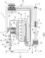
- FIG.1 is a schematic representation of an internal combustion engine as a natural gas engine 1 with a regulated and cooled exhaust gas recirculation 2:
- An air mass flow (arrow 3) is passed through a charge air cooler 6 by means of a compressor 4, which is part of an exhaust gas turbocharger 5.
- the cooled air mass flow 3 is fed via a controllable throttle valve 7 to a gas mixer 8, to which a gas mass flow (arrow 9) is also fed.
- the gas mixture flows to the intake manifold of the engine block 10 with its cylinder-piston units 11, in which the combustion process takes place.
- an exhaust gas mass flow (arrow 12) flows through a turbine 13 of the exhaust gas turbocharger 5, whereby the turbine 13 is mechanically coupled to the compressor 4 and drives it.
- an exhaust gas recirculation mass flow (EGR mass flow) is branched off at a branching point 17 and fed via an EGR control valve 15 and an EGR cooler 16 to a branching point 18 to the gas mass flow downstream of the gas mixer 8 and upstream of the engine block 10.
- a pressure sensor 19 is arranged upstream of the charge air cooler 6 (p-vLLK sensor) and further, downstream of the charge air cooler 6, a pressure sensor 20 (p-nLLK sensor) is arranged in the air mass flow 3.
- the measurement signals of the pressure sensors 19, 20 corresponding to a differential pressure are fed to a computing unit 21, in which the size of the currently requested air mass flow 3 is calculated therefrom.
- a pressure sensor 22 preferably as a MAP intake manifold pressure sensor, is arranged to measure the intake manifold pressure, with which the total mass flow of fresh air, fuel gas and recirculated exhaust gas can be determined in a delivery efficiency model, for example in the computing unit 21.
- the determined air mass flow 3 which was calculated using the pressure sensors 19, 20 via the pressure drop at the charge air cooler 6, can be deducted from this total mass flow.
- the gas mass flow 9 can be determined via a known blow-in duration of injectors and/or via a known combustion air ratio and also deducted from the total mass flow, so that the remaining difference then gives the proportion of the currently recirculated exhaust gas as an EGR mass flow corresponding to an EGR rate or an EGR actual value.
- This EGR actual value is thus calculated without its direct measurement.
- Fig. 2 is the natural gas engine 1 of Fig.1 in a more concrete representation with further details, whereby identical components from Fig.1 are marked with the same reference symbols.
- an air mass flow (arrow 3) is fed via an air filter 23 to the compressor 4 of the exhaust gas turbocharger 5 and from there is fed to the gas mixer 8 via the charge air cooler 6 and the throttle valve 7.
- the gas mass flow 9 is also fed to the gas mixer 8 from a high-pressure accumulator 24 for compressed natural gas (CNG high-pressure accumulator for compressed natural gas) via a high-pressure shut-off valve 25, a gas pressure regulator 26 in conjunction with a pressure relief valve 27 and a low-pressure shut-off valve 28.
- the gas mixer 8 is connected to an intake manifold 29 on the engine block 10, with connecting lines leading from the intake manifold 29 to the six cylinder-piston units 30, which are only examples here.
- Injection valves 31 are provided in the gas mixer 8 for metering the gas mass flow 9.
- the exhaust gas mass flow (arrow 12) is guided via the turbine 13 of the exhaust gas turbocharger 5 and via a downstream catalyst, e.g. a 3-way catalyst 32, with a silencer.
- an EGR mass flow 14 is branched off from the exhaust gas flow and returned via a cooled exhaust gas recirculation unit 33 between the throttle valve 7 and the gas mixer 8.
- the EGR mass flow 14 is cooled indirectly via a coolant, which is cooled in a water cooler 34, which is arranged here in a compact manner between the charge air cooler 6 and a further associated fan 35, to a predetermined temperature detected by a coolant temperature sensor 36.
- the fan 35, the water cooler 34 associated with it and the charge air cooler 6 associated with it can be combined to form a structural unit or can also be formed by separate components that are simply associated with one another.
- the p-vLLK sensor 19 and the p-nLLK sensor 20 are arranged in the air mass flow 3, wherein both sensors 19, 20 are preferably further equipped with a temperature sensor.
- the MAP intake manifold pressure sensor 22 is also attached to the intake manifold 29. Upstream of the gas mixer 8, a CNG pressure sensor 37 and a CNG temperature sensor 38 are arranged in the gas line for the gas mass flow 9.
- a broadband lambda probe 39 is arranged upstream of the catalyst 32 and a lambda jump probe 40 is arranged downstream of the catalyst 32.
- the currently requested air mass flow 3 is determined via a pressure loss measurement using the pressure sensors 19, 20 above the charge air cooler 6, if necessary in conjunction with a throttle valve model (not shown). The value obtained from this can be used in particular for EGR control.
Landscapes
- Engineering & Computer Science (AREA)
- Chemical & Material Sciences (AREA)
- General Engineering & Computer Science (AREA)
- Combustion & Propulsion (AREA)
- Mechanical Engineering (AREA)
- Chemical Kinetics & Catalysis (AREA)
- General Chemical & Material Sciences (AREA)
- Oil, Petroleum & Natural Gas (AREA)
- Physics & Mathematics (AREA)
- Thermal Sciences (AREA)
- Analytical Chemistry (AREA)
- Exhaust-Gas Circulating Devices (AREA)
- Combined Controls Of Internal Combustion Engines (AREA)
- Electrical Control Of Air Or Fuel Supplied To Internal-Combustion Engine (AREA)
Description
- Die Erfindung betrifft eine Brennkraftmaschine welche als Gasmotor ausgebildet ist für ein Kraftfahrzeug nach Anspruch 1 sowie ein Verfahren zum Betreiben einer Brennkraftmaschine nach Anspruch 7.
- Es ist allgemein bekannt, zur Verbesserung des Wirkungsgrades einer Brennkraftmaschine, insbesondere eines Gasmotors eine gekühlte und geregelte Abgasrückführung (AGR) zu verwenden. Das rückgeführte Abgas wirkt als Zugabe von Inertgas zum Gasgemisch einer Klopfneigung entgegen, so dass damit eine Erhöhung des Verdichtungsverhältnisses und damit eine Wirkungsgradverbesserung möglich ist. Zusätzlich erfolgt bei der Anwendung einer Abgasrückführung eine Wirkungsgradsteigerung im Teil- und Schwachlastbereich durch Absenkung der Ladungswechselverluste.
- Für den Betrieb einer Brennkraftmaschine wird in an sich bekannter Weise je nach Leistungsanforderung Kraftstoff zum zugeordneten Luftmassenstrom zudosiert. Für eine vorgegebene Zudosierung von Kraftstoff ist eine möglichst genaue Bestimmung des jeweiligen Luftmassenstroms erforderlich:
Es ist bekannt, bei Brennkraftmaschinen ohne Abgasrückführung den Luftmassenstrom durch eine Messung des Manifold Absolute Pressure (MAP) entsprechend einem Saugrohrdruck zu bestimmen. Dabei wird über ein Modell, welches das Schluckvermögen des Motors in Abhängigkeit der Drehzahl (Liefergradmodell) widerspiegelt die Zylinderfüllung berechnet. Aus der Zylinderfüllung wird wiederum unter Berücksichtigung der Motordrehzahl der Luftmassenstrom des gesamten Motors berechnet. Diese Vorgehensweise ist jedoch bei Brennkraftmaschinen mit Abgasrückführung, insbesondere bei Gasmotoren mit einer Abgasrückführung nicht möglich, da diese in der vorstehenden Berechnung nicht berücksichtigt wird. - Es ist auch bereits eine Bestimmung des Luftmassenstroms bekannt, welche bei Brennkraftmaschinen, insbesondere bei Gasmotoren mit Abgasrückführung (AGR) verwendet wird. Dabei wird der Luftmassenstrom in der Luftmassenstromzuführung vor der Zumischung des Kraftstoffs und vor Zumischung des rückgeführten Abgases direkt mit Hilfe eines speziellen Luftmassenmessers gemessen. Dazu ist ein Heißfilmluftmassenmesser (HFM) bekannt. Ein solcher Heißfilmluftmassenmesser ist teuer und kann störanfällig sein. Insbesondere hat sich ein HFM bei Erdgasmotoren (EURO V) aufgrund seiner Schmutzempfindlichkeit als sehr störanfällig erwiesen.
- Aus der
DE 10 2007 010 501 A1 ist ein Verfahren zur Bestimmung einer Abgasrückführmasse bekannt. - Die
EP 1 662 127 A2 und dieUS 2014/034026A1 beschreiben jeweils eine Vorrichtung zur Abschätzung einer Ansaugluftmenge einer Brennkraftmaschine. - Die
DE 10 2013 213 351 A1 zeigt ein Verfahren zum Betrieb einer Gas-Brennkraftmaschine. - Aufgabe der Erfindung ist es, eine Brennkraftmaschine welche als Gasmotor ausgebildet ist, sowie ein Verfahren zum Betreiben einer derartigen Brennkraftmaschine mit einem Ladeluftkühler vorzuschlagen, mit der bzw. mit dem eine alternative, kostengünstige und funktionssichere Bestimmung des Luftmassenstroms möglich ist.
- Diese Aufgabe wird gelöst mit den Merkmalen der unabhängigen Ansprüche.
- Bevorzugte Ausgestaltungen sind Gegenstand der darauf rückbezogenen Unteransprüche.
- Gemäß Anspruch 1 wird eine Brennkraftmaschine welche als Gasmotor ausgebildet ist für ein Kraftfahrzeug vorgeschlagen, die einen in einer Luftmassenstromzuführung stromauf einer Vorrichtung zur Kraftstoffzumischung angeordneten Ladeluftkühler sowie eine Messeinrichtung zur Bestimmung des Luftmassenstroms aufweist.
- Erfindungsgemäß ist vorgesehen, dass eine Messeinrichtung eine Sensorik zur Messung eines Druckverlusts über dem Ladeluftkühler aufweist. Die Messeinrichtung umfasst weiter eine Recheneinheit als Auswerteeinheit, mit der in einem dort abgelegten Ladeluftkühlermodell, in dem der Ladeluftkühler eine geometrisch konstante Drossel für den durchströmenden Luftmassenstrom bildet, wenigstens aus dem mittels der Sensorik gemessenen Druckverlust der Luftmassenstrom berechenbar ist bzw. berechnet wird.
- Bei einem auf ein bestimmtes Bauteil bezogenen Modell, zum Beispiel dem vorstehend genannten Ladeluftkühlermodell bzw. dem nachstehend noch genannten Drosselklappenmodell, handelt es sich vorliegend stets um eine in einer Rechnereinheit abgelegte, dieses Bauteil beschreibende mathematische Funktion und/oder Kennlinien bzw. Kennfelder, mit dem eine Prozessgröße in Abhängigkeit von definiert vorgegebenen Eingangssignalen berechnet wird.
- Bezogen auf das Ladeluftkühlermodell bedeutet dies, dass der Ladeluftkühler hier eine von einem Luftmassenstrom durchströmte geometrisch konstante Drossel ist, für die wenigstens aus dem mittels der Sensorik gemessenen Druckverlust als Eingangsgröße der Luftmassenstrom berechenbar ist. Neben dem Druckverlust können selbstverständlich auch noch weitere Parameter bzw. Eingangsgrößen berücksichtigt werden, zum Beispiel Motorparameter, AGR-Parameter oder dergleichen. Eine geometrisch konstante Drossel ist hierbei eine Drossel mit einer Geometrie, bei der der Druckverlust im Wesentlichen linear zu dem die Drossel durchströmenden Massenstrom ist.
- Die Erfindung nutzt somit den physikalischen Effekt des Druckverlusts einer Drosselung in einem Gasstrom. Ein solcher Druckverlust ist, wie erfinderseitige Versuche gezeigt haben, annähernd linear zum Massenstrom, der durch die Drossel fließt. Konkret ist es für die vorliegende Bestimmung des Luftmassenstroms somit erforderlich, die Ladeluftkühler-Drosselcharakteristik als Grundlage für die Berechnung vorab durch Messungen zu bestimmen.
- Vorteilhaft kann mit der erfindungsgemäßen Bestimmung des Luftmassenstroms damit ein teurer und störanfälliger Heißfilmluftmassenmesser (HFM) entfallen.
- Die Sensorik zur Messung des Druckverlusts am Ladeluftkühler kann durch jeweils einen Drucksensor stromauf und stromab des Ladeluftkühlers oder alternativ durch einen Differenzdrucksensor gebildet werden. Zusätzlich kann auch wenigstens ein Temperatursensor zur Messung der Temperatur des Luftmassenstroms verwendet werden, wobei dann die Temperatur gegebenenfalls bei der Berechnung zur Steigerung der Genauigkeit mit berücksichtigt werden kann.
- Üblicherweise wird bei einer Brennkraftmaschine welche als Gasmotor ausgebildet ist die Lastanforderung mittels einer verstellbaren Drosselklappe in der Luftmassenstromzuführung vorgegeben, welche damit als variable Drossel wirkt. Somit kann in einem Drosselklappenmodell, in dem die Drosselklappe als eine vom Luftmassenstrom durchströmte geometrisch veränderliche Drossel definiert ist, der Luftmassenstrom auch anhand des mittels einer Sensorik gemessenen Druckverlusts über der Drosselklappe und der mittels der Sensorik erfassten Drosselklappenstellung bestimmt werden. Im Schwachund unterem Teillastbereich ist die Drosselwirkung durch die Drosselklappe für die Ausbildung gut messbarer Druckunterschiede und damit für eine genaue Luftmassenbestimmung ausreichend hoch. Im volllastnahen Bereich bei weitgehend offener Drosselklappe sind diese messbaren Druckunterschiede jedoch so gering, dass damit eine zur Kraftstoff-Zudosierung ausreichend genaue Luftmassenbestimmung aufgrund der flachen Kennlinie in diesem Bereich nicht mehr befriedigend möglich ist.
- Das Drosselklappenmodell ist somit ein Modell, bei dem die Drosselklappe als eine von einem Luftmassenstrom durchströmte geometrisch veränderliche Drossel angenommen wird, für die wenigstens aus dem mittels der Sensorik gemessenen Druckverlust und der mittels der Sensorik gemessenen Drosselklappenstellung als Eingangsgrößen der Luftmassenstrom berechenbar ist.
- Erfindungsgemäß wird daher vorgeschlagen, dass im Schwachlastbereich der Luftmassenstrom mittels des Drosselklappenmodells und in hohen Lastbereichen mittels des Ladeluftkühlermodells bestimmt wird. Im dem wenigstens einen dazwischenliegenden mittleren Lastbereich ergeben beide Möglichkeiten ausreichend gute Ergebnisse und können somit alternativ oder gegebenenfalls parallel für einen kontinuierlichen Abgleich, gegebenenfalls in Verbindung mit einer Lambda-Regelung, verwendet werden.
- Die erfindungsgemäße Erfassung des Luftmassenstroms ist vorteilhaft bei einer Brennkraftmaschine welche als Gasmotor ausgebildet ist die eine Abgasrückführung (AGR) in die Luftmassenstromzuführung, vorzugsweise in die Luftmassenstromzuführung stromab des Ladeluftkühlers, aufweist. Besonders bevorzugt ist diese Abgasrückführung hierbei eine geregelte und/oder gekühlte Abgasrückführung, wobei dann der Anteil des rückgeführten Abgases als AGR-Rate bzw. AGR-Istwert mittels der Recheneinheit berechnet wird. Dazu wird der Gesamtmassenstrom aus Frischluft, Brenngas und rückgeführtem Abgas durch Messung des Saugrohrdrucks (Manifold Absolute Pressure) mit einem MAP-Sensor in einem Liefergradmodell bestimmt. Vom Gesamtmassenstrom wird der ermittelte und damit bekannte Luftmassenstrom sowie der Brenngasmassenstrom abgezogen. Der Brenngasmassenstrom kann über eine jeweils bekannte Einblasdauer von Injektoren und/oder über ein jeweils bekanntes Verbrennungsluftverhältnis aus einer Lambdamessung mittels Lambdasonde bestimmt werden. Die dann verbleibende Differenz ergibt den Anteil des aktuell rückgeführten Abgases als AGR-Rate bzw. als AGR-Istwert.
- Diese Berechnung der AGR-Rate bzw. der AGR-Istwerts kann dann in einem Regelkreis auf vorgegebene AGR-Sollwerte geregelt werden. Ein solcher AGR-Regler kann ebenso wie die vorstehende Recheneinheit in einem Motorsteuergerät integriert sein, wobei die AGR-Sollwerte in einem Kennfeld abgelegt sein können.
- Da sich eine Luftmassenstrommessung mit einem HFM-Sensor besonders bei Gasmotoren als sehr störanfällig erwiesen hat, kann die alternative, erfindungsgemäße Bestimmung des Luftmassenstroms ohne HFM-Sensor besonders vorteilhaft bei Gasmotoren verwendet werden.
- Die sich mit dem erfindungsgemäßen Verfahren und dem ebenfalls beanspruchten Fahrzeug ergebenden Vorteile sind identisch mit den zuvor zur Brennkraftmaschine genannten Vorteilen, so dass zur Vermeidung von Wiederholungen auf die vorstehenden Ausführungen verwiesen wird.
- Anhand einer Zeichnung wird ein Ausführungsbeispiel der Erfindung lediglich schematisch und beispielhaft näher erläutert.
- Es zeigen:
- Fig. 1
- eine Schemadarstellung eines Erdgasmotors mit geregelter und gekühlter Abgasrückführung, und
- Fig. 2
- eine konkretere Darstellung entsprechend
Fig. 1 . - In
Fig. 1 ist eine Schemadarstellung einer Brennkraftmaschine als Erdgasmotor 1 mit einer geregelten und gekühlten Abgasrückführung 2 dargestellt:
Ein Luftmassenstrom (Pfeil 3) wird mittels eines Verdichters 4, der Bestandteil eines Abgasturboladers 5 ist, durch einen Ladeluftkühler 6 geleitet. Von dort wird der gekühlte Luftmassenstrom 3 über eine steuerbare Drosselklappe 7 einem Gasmischer 8 zugeführt, dem weiter ein Gasmassenstrom (Pfeil 9) zugeführt wird. Von dort strömt das Gasgemisch zum Saugrohr des Motorblocks 10 mit seinen Zylinder-Kolben-Einheiten 11, in denen der Verbrennungsprozess stattfindet. Von dort strömt ein Abgasmassenstrom (Pfeil 12) über eine Turbine 13 des Abgasturboladers 5, wobei die Turbine 13 mechanisch mit dem Verdichter 4 gekoppelt ist und diesen antreibt. - Stromauf der Turbine 13 wird an einer Verzweigungsstelle 17 ein Abgasrückführ-Massenstrom (AGR-Massenstrom) entsprechend 14 abgezweigt und über ein AGR-Regelventil 15 und einen AGR-Kühler 16 an einer Verzweigungsstelle 18 dem Gasmassenstrom stromab des Gasmischers 8 sowie stromauf des Motorblocks 10 zugeführt.
- Zur Messung eines Druckverlustes über dem Ladeluftkühler 6 sind hier ein Drucksensor 19 stromauf des Ladeluftkühlers 6 (p-vLLK-Sensor) und weiter, stromab des Ladeluftkühlers 6, ein Drucksensor 20 (p-nLLK-Sensor) im Luftmassenstrom 3 angeordnet. Die Messsignale der Drucksensoren 19, 20 entsprechend einem Differenzdruck werden einer Recheneinheit 21 zugeführt, in der daraus die Größe des aktuell angeforderten Luftmassenstroms 3 berechnet wird.
- Stromauf des Motorblocks 10 und stromab der Verzweigungsstelle 18 ist ein Drucksensor 22, bevorzugt als MAP-Saugrohrdrucksensor, zur Messung des Saugrohrdrucks angeordnet, mit dem in einem Liefergradmodell der Gesamtmassenstrom aus Frischluft, Brenngas und rückgeführtem Abgas zum Beispiel in der Recheneinheit 21 bestimmt werden kann. Von diesem Gesamtmassenstrom kann der ermittelte Luftmassenstrom 3, der mittels der Drucksensoren 19, 20 über den Druckabfall am Ladeluftkühler 6 berechnet wurde, abgezogen werden. Weiter kann der Gasmassenstrom 9 über eine jeweils bekannte Einblasdauer von Injektoren und/oder über ein jeweils bekanntes Verbrennungsluftverhältnis ermittelt und ebenfalls vom Gesamtmassenstrom abgezogen werden, so dass dann die verbleibende Differenz den Anteil des aktuell rückgeführten Abgases als AGR-Massenstrom entsprechend einer AGR-Rate bzw. einem AGR-Istwert ergibt. Dieser AGR-Istwert wird somit ohne seine direkte Messung berechnet.
- In
Fig. 2 ist der Erdgasmotor 1 vonFig. 1 in einer mehr konkretisierten Darstellung mit weiteren Einzelheiten dargestellt, wobei gleiche Bauteile ausFig. 1 mit gleichen Bezugszeichen gekennzeichnet sind. - Ersichtlich ist auch hier ein Luftmassenstrom (Pfeil 3) über einen Luftfilter 23 dem Verdichter 4 des Abgasturboladers 5 zugeführt und wird von dort über den Ladeluftkühler 6 und die Drosselklappe 7 dem Gasmischer 8 zugeführt. Dem Gasmischer 8 wird zudem aus einem Hochdruckspeicher 24 für komprimiertes Erdgas (CNG-Hochdruckspeicher für Compressed Natural Gas) über ein Hochdruck-Absperrventil 25, einen Gasdruckregler 26 in Verbindung mit einem Überdruckventil 27 und einem Niederdruck-Absperrventil 28 der Gasmassenstrom 9 zugeführt. Der Gasmischer 8 ist mit einem Saugrohr 29 am Motorblock 10 verbunden, wobei vom Saugrohr 29 jeweils Verbindungsleitungen zu den hier lediglich beispielhaft sechs Zylinder-Kolben-Einheiten 30 abgehen. Zur Zudosierung des Gasmassenstroms 9 sind im Gasmischer 8 Einblasventile 31 vorgesehen.
- Der Abgasmassenstrom (Pfeil 12) wird auch hier über die Turbine 13 des Abgasturboladers 5 und über einen nachgeordneten Katalysator, z.B. einen 3-Wege-Katalysator 32, mit Schalldämpfer geführt. Auch hier wird vom Abgasstrom ein AGR-Massenstrom 14 abgezweigt und über eine gekühlte Abgasrückführeinheit 33 zwischen der Drosselklappe 7 und dem Gasmischer 8 zurückgeführt. Die Kühlung des AGR-Massenstroms 14 erfolgt hier indirekt über ein Kühlmittel, welches in einem Wasserkühler 34, der hier in kompakter Weise zwischen dem Ladeluftkühler 6 und einem weiter zugeordneten Lüfter 35 angeordnet ist, auf eine vorgegebene, mittels eines Kühlmittel-Temperatursensors 36 erfasste Temperatur gekühlt wird. Der Lüfter 35, der diesem zugeordnete Wasserkühler 34 sowie der diesen zugeordnete Ladeluftkühler 6 können dabei zu einer Baueinheit zusammengefasst sein oder aber auch durch einander lediglich zugeordnete separate Bauteile gebildet sein.
- Weiter sind der p-vLLK-Sensor 19 und der p-nLLK-Sensor 20 im Luftmassenstrom 3 angeordnet, wobei beide Sensoren 19, 20 bevorzugt weiter mit einem Temperatursensor ausgerüstet sind.
- Am Saugrohr 29 ist zudem der MAP-Saugrohrdrucksensor 22 angebracht. Stromauf des Gasmischers 8 sind in der Gasleitung für den Gasmassenstrom 9 ein CNG-Drucksensor 37 und ein CNG-Temperatursensor 38 angeordnet.
- Stromauf des Katalysators 32 sind im Abgasmassenstrom 12 hier zudem beispielhaft eine Breitbandlambdasonde 39 und stromab des Katalysators 32 eine Lambdasprungsonde 40 angeordnet.
- Auch in der konkreter dargestellten Ausführungsform eines Erdgasmotors 1 nach
Fig. 2 wird der jeweils aktuell angeforderte Luftmassenstrom 3 über eine Druckverlustmessung mittels der Drucksensoren 19, 20 über dem Ladeluftkühler 6 gegebenenfalls in Verbindung mit einem (nicht dargestellten) Drosselklappenmodell bestimmt. Der daraus gewonnene Wert kann insbesondere für eine AGR-Regelung herangezogen werden. -
- 1
- Erdgasmotor
- 2
- Abgasrückführung
- 3
- Pfeil (Luftmassenstrom)
- 4
- Verdichter
- 5
- Abgasturbolader
- 6
- Ladeluftkühler
- 7
- Drosselklappe
- 8
- Gasmischer
- 9
- Pfeil (Gasmassenstrom)
- 10
- Motorblock
- 11
- Zylinder-Kolben-Einheit
- 12
- Pfeil (Abgasmassenstrom
- 13
- Turbine
- 14
- AGR-Massenstrom
- 15
- AGR-Regelventil
- 16
- AGR-Kühler
- 17
- Verzweigungsstelle
- 18
- Verzweigungsstelle
- 19
- p-vLLK-Sensor
- 20
- p-nLLK-Sensor
- 21
- Recheneinheit
- 22
- MAP-Saugrohrdrucksensor
- 23
- Luftfilter
- 24
- Hochdruckspeicher
- 25
- Hochdruck-Absperrventil
- 26
- Gasdruckregler
- 27
- Überdruckventil
- 28
- Niederdruck-Absperrventil
- 29
- Saugrohr
- 30
- Zylinder-Kolben-Einheit
- 31
- Einblasventil
- 32
- 3-Wege-Katalysator
- 33
- Abgasrückführeinheit
- 24
- Wasserkühler
- 35
- Lüfter
- 36
- Kühlmittel-Temperatursensor
- 37
- CNG-Drucksensor
- 38
- CNG-Temperatursensor
- 39
- Breitbandlambdasonde
- 40
- Lambdasprungsonde
Claims (11)
- Brennkraftmaschine, als Gasmotor ausgebildet, für ein Kraftfahrzeug,mit einem in einer Luftmassenstromzuführung stromauf einer Vorrichtung zur Kraftstoffzumischung (8) angeordneten Ladeluftkühler (6), undmit einer Messeinrichtung zur Bestimmung des Luftmassenstroms (3), wobei die Messeinrichtung eine Sensorik (19, 20) zur Messung eines Druckverlustes über dem Ladeluftkühler (6) aufweist,wobei die Messeinrichtung weiter eine Recheneinheit (21) als Auswerteeinheit aufweist, mit der in einem dort abgelegten Ladeluftkühlermodell, in dem der Ladeluftkühler (6) eine geometrisch konstante Drossel für den durchströmenden Luftmassenstrom (3) bildet, wenigstens aus dem mittels der Sensorik (19, 20) gemessenen Druckverlust der Luftmassenstrom (3) berechenbar ist,wobei die Messeinrichtung eine Sensorik zur Messung eines Druckverlustes über einer Drosselklappe (7) und zur Messung einer Drosselklappenstellung aufweist, wobei die Drosselklappe (7) in einem in der Recheneinheit (21) abgelegten Drosselklappenmodell eine geometrisch veränderliche Drossel für den durchströmenden Luftmassenstrom (3) bildet, so dass mittels der Recheneinheit (21) wenigstens aus dem jeweiligen Druckverlust an der Drosselklappe (7) und der Drosselklappenstellung der Luftmassenstrom (3) berechenbar ist, undwobei die Messeinrichtung so ausgebildet ist, dass im Schwachlastbereich der Brennkraftmaschine (1) die Bestimmung des Luftmassenstroms (3) mittels des Drosselklappenmodells, und im hohen Lastbereich mittels des Ladeluftkühlermodells durchführbar ist, dadurch gekennzeichnet,dass in wenigstens einem dazwischen liegenden mittleren Lastbereich die Bestimmung des Luftmassenstroms (3) mittels des Drosselklappenmodells und des Ladeluftkühlermodells erfolgt und ein kontinuierlicher Abgleich der Ergebnisse beider Modelle, gegebenenfalls in Verbindung mit einer Lambda-Regelung, durchführbar ist.
- Brennkraftmaschine nach Anspruch 1, dadurch gekennzeichnet, dass die Sensorik zur Messung des Druckverlustes am Ladeluftkühler (6) einen Drucksensor (19) stromauf des Ladeluft-Kühlers (p-vLLK-Sensor) und einen Drucksensor (20) stromab des Ladeluftkühlers (p-nLLK-Sensor) aufweist, oder dass die Sensorik durch einen Differenzdrucksensor gebildet ist, wobei bevorzugt vorgesehen ist, dass die Sensorik zusätzlich einen Temperatursensor zur Messung der Temperatur des Luftmassenstroms (3) aufweist.
- Brennkraftmaschine nach einem der vorhergehenden Ansprüche, dadurch gekennzeichnet, dass die Brennkraftmaschine (1) eine Abgasrückführung (AGR) (2) in die Luftmassenstromzuführung aufweist, vorzugsweise stromab des Ladeluftkühlers (6).
- Brennkraftmaschine nach Anspruch 3, dadurch gekennzeichnet, dass die Abgasrückführung (2) eine geregelte und/oder gekühlte Abgasrückführung (2) ist, wobei der Anteil (14) des rückgeführten Abgases (AGR-Rate als AGR-Istwert) mittels der Recheneinheit (21) berechenbar ist, insbesondere dergestalt, dass dazu der Gesamtmassenstrom aus Frischluft, Brenngas und rückgeführtem Abgas durch Messung (22) des Saugrohrdrucks in einem Liefergradmodell bestimmt wird,
dass weiter vom Gesamtmassenstrom der ermittelte bekannte Luftmassenstrom (3) sowie der Brenngasmassenstrom (9) abgezogen werden, wobei der Brenngasmassenstrom (9) über eine jeweils bekannte Einblasdauer von Injektoren und/oder über ein jeweils bekanntes Verbrennungsluftverhältnis aus einer Lambdamessung mittels Lambdasonde (39, 40) bestimmt wird, und dass weiter die verbleibende Differenz den Anteil (14) des aktuell rückgeführten Abgases als AGR-Rate entsprechend einem AGR-Istwert ergibt. - Brennkraftmaschine nach Anspruch 4, dadurch gekennzeichnet, dass eine AGR-Rate (14) und/oder ein AGR-Istwert in einem Regelkreis auf vorgegebene AGR-Sollwerte regelbar ist oder sind, wobei bevorzugt vorgesehen ist, dass ein AGR-Regler, gegebenenfalls auch die Recheneinheit (21), in ein Motorsteuergerät integriert ist oder sind, und die AGR-Sollwerte in einem Kennfeld abgelegt sind.
- Brennkraftmaschine nach einem der vorhergehenden Ansprüche, dadurch gekennzeichnet, dass die Brennkraftmaschine ein mit Erdgas betriebener Gasmotor ist.
- Verfahren zum Betreiben einer als Gasmotor ausgebildeten Brennkraftmaschine für ein Kraftfahrzeug, nach einem der vorhergehenden Ansprüche,bei dem in einer Luftmassenstromzuführung stromauf einer Vorrichtung zur Kraftstoffzumischung (8) ein Ladeluftkühler (6) angeordnet ist, und bei dem eine Messeinrichtung zur Bestimmung des Luftmassenstroms (3) vorgesehen ist,wobei die Messeinrichtung eine Sensorik (19, 20) zur Messung eines Druckverlustes über dem Ladeluftkühler (6) aufweist,wobei die Messeinrichtung weiter eine Recheneinheit (21) als Auswerteeinheit aufweist, mit der in einem dort abgelegten Ladeluftkühlermodell, in dem der Ladeluftkühler (6) eine geometrisch konstante Drossel für den durchströmenden Luftmassenstrom (3) bildet, aus dem mittels der Sensorik (19, 20) gemessenen Druckverlust der Luftmassenstrom (3) berechnet wird,wobei die Messeinrichtung eine Sensorik zur Messung eines Druckverlustes über einer Drosselklappe (7) und zur Messung einer Drosselklappenstellung aufweist, wobei die Drosselklappe (7) in einem in der Recheneinheit (21) abgelegten Drosselklappenmodell eine geometrisch veränderliche Drossel für den durchströmenden Luftmassenstrom (3) bildet, so dass mittels der Recheneinheit (21) wenigstens aus dem jeweiligen Druckverlust an der Drosselklappe (7) und der Drosselklappenstellung der Luftmassenstrom (3) berechnet wird,wobei im definiert vorgegebenen Schwachlastbereich der Brennkraftmaschine (1) die Bestimmung des Luftmassenstroms (3) mittels des Drosselklappenmodells, und im definiert vorgegebenen hohen Lastbereich mittels des Ladeluftkühlermodells erfolgt, dadurch gekennzeichnet, dass in wenigstens einem dazwischen liegenden mittleren Lastbereich die Bestimmung des Luftmassenstroms (3) mittels des Drosselklappenmodells und des Ladeluftkühlermodells erfolgt und ein kontinuierlicher Abgleich der Ergebnisse beider Modelle gegebenenfalls in Verbindung mit einer Lambda-Regelung erfolgt.
- Verfahren nach Anspruch 7, dadurch gekennzeichnet,dass die Brennkraftmaschine (1) eine geregelte und/oder gekühlte Abgasrückführung (2) aufweist, wobei der Anteil (14) des rückgeführten Abgases (AGR-Rate als AGR-Istwert) mittels der Recheneinheit (21) berechnet wird,dass dazu der Gesamtmassenstrom aus Frischluft, Brenngas und rückgeführtem Abgas durch Messung (22) des Saugrohrdrucks in einem Liefergradmodell bestimmt wird,dass vom Gesamtmassenstrom der ermittelte bekannte Luftmassenstrom (3) sowie der Brenngasmassenstrom (9) abgezogen werden, wobei der Brenngasmassenstrom (9) über eine jeweils bekannte Einblasdauer von Injektoren und/oder über ein jeweils bekanntes Verbrennungsluftverhältnis aus einer Lambdamessung mittels Lambdasonde (39, 40) bestimmt wird, unddass die verbleibende Differenz den Anteil (14) des aktuell rückgeführten Abgases als AGR-Rate entsprechend einem AGR-Istwert ergibt.
- Verfahren nach Anspruch 8, dadurch gekennzeichnet, dass eine AGR-Rate (14) und/oder ein AGR-Istwert in einem Regelkreis auf vorgegebene AGR-Sollwerte geregelt wird.
- Verfahren nach einem der Ansprüche 7 bis 9, dadurch gekennzeichnet, dass für das Ladeluftkühlermodell die Luftkühler-Drosselcharakteristik als konstante Charakteristik gemessen wird und für die Berechnung des Luftmassenstroms (3) ein annähernd linearer Zusammenhang zwischen Druckverlust und Massenstrom zugrunde gelegt wird.
- Fahrzeug, insbesondere Nutzfahrzeug, mit einer Brennkraftmaschine (1) nach einem der vorhergehenden Ansprüche 1 bis 6, insbesondere zur Durchführung eines Verfahrens nach einem der Ansprüche 7 bis 10.
Applications Claiming Priority (1)
| Application Number | Priority Date | Filing Date | Title |
|---|---|---|---|
| DE102014003276.0A DE102014003276A1 (de) | 2014-03-12 | 2014-03-12 | Brennkraftmaschine,insbesondere Gasmotor,für ein Kraftfahrzeug |
Publications (2)
| Publication Number | Publication Date |
|---|---|
| EP2921678A1 EP2921678A1 (de) | 2015-09-23 |
| EP2921678B1 true EP2921678B1 (de) | 2024-08-21 |
Family
ID=52394080
Family Applications (1)
| Application Number | Title | Priority Date | Filing Date |
|---|---|---|---|
| EP15000122.0A Active EP2921678B1 (de) | 2014-03-12 | 2015-01-17 | Brennkraftmaschine, insbesondere Gasmotor, für ein Kraftfahrzeug |
Country Status (6)
| Country | Link |
|---|---|
| US (1) | US9500153B2 (de) |
| EP (1) | EP2921678B1 (de) |
| CN (1) | CN104963780B (de) |
| BR (1) | BR102015003834B1 (de) |
| DE (1) | DE102014003276A1 (de) |
| RU (1) | RU2675645C2 (de) |
Families Citing this family (8)
| Publication number | Priority date | Publication date | Assignee | Title |
|---|---|---|---|---|
| DE102014013284A1 (de) * | 2014-09-12 | 2016-03-17 | Man Truck & Bus Ag | Brennkraftmaschine, insbesondere Gasmotor, für ein Fahrzeug, insbesondere für ein Nutzfahrzeug |
| DE102016106068A1 (de) * | 2016-04-04 | 2017-10-05 | Iav Gmbh Ingenieurgesellschaft Auto Und Verkehr | Verfahren zur Bestimmung der Temperatur eines Kühlmediums im Vorlauf eines Wärmeübertragers |
| DE102016205680A1 (de) * | 2016-04-06 | 2017-10-12 | Robert Bosch Gmbh | Verfahren und Vorrichtung zum Bestimmen eines Frischluftmassenstroms in einen Verbrennungsmotor |
| DE102017209127A1 (de) * | 2017-05-31 | 2018-12-06 | Robert Bosch Gmbh | Verfahren zum Berechnen eines Massenstroms von einem Tankentlüftungssystem in ein Saugrohr eines Verbrennungsmotors |
| DE102018220391A1 (de) * | 2018-11-28 | 2020-05-28 | Robert Bosch Gmbh | Verfahren zur Ermittlung eines Luftmassenstroms für eine Verbrennungskraftmaschine |
| DE102020106531B4 (de) * | 2020-03-10 | 2026-04-23 | Bayerische Motoren Werke Aktiengesellschaft | Betriebsverfahren einer Frischluftzuführeinrichtung, Verwendung einer solchen Frischluftzuführungseinrichtung in einer Brennkraftmaschine und Brennkraftmaschine mit einer derartigen Frischluftzuführeinrichtung |
| CN112664361B (zh) * | 2020-12-24 | 2022-08-26 | 天津大学 | 内燃机清洁燃烧的分层喷射再循环废气系统装置 |
| CN115387940B (zh) * | 2022-07-29 | 2024-02-27 | 中国第一汽车股份有限公司 | 多缸发动机的压力控制方法、装置、存储介质及处理器 |
Citations (1)
| Publication number | Priority date | Publication date | Assignee | Title |
|---|---|---|---|---|
| DE102007010501A1 (de) * | 2007-03-05 | 2008-09-11 | Robert Bosch Gmbh | Verfahren zur Bestimmung einer Abgasrückführmasse |
Family Cites Families (34)
| Publication number | Priority date | Publication date | Assignee | Title |
|---|---|---|---|---|
| US5191789A (en) * | 1990-11-27 | 1993-03-09 | Japan Electronic Control Systems Co., Ltd. | Method and system for detecting intake air flow rate in internal combustion engine coupled with supercharger |
| US5904131A (en) * | 1995-12-28 | 1999-05-18 | Cummins Engine Company, Inc. | Internal combustion engine with air/fuel ratio control |
| JP2001516421A (ja) * | 1997-04-01 | 2001-09-25 | ローベルト ボツシユ ゲゼルシヤフト ミツト ベシユレンクテル ハフツング | 内燃機関のシリンダ内に過給器を用いて供給される空気量を決定するための装置 |
| DE19963358A1 (de) * | 1999-12-28 | 2001-07-12 | Bosch Gmbh Robert | Verfahren und Vorrichtung zur Steuerung einer Brennkraftmaschine mit einem Luftsystem |
| DE10122293A1 (de) * | 2001-05-08 | 2002-11-21 | Audi Ag | Verfahren zur Regelung einer Ladedruckbegrenzung eines Turboladers bei einem Verbrennungsmotor in Abhängigkeit von der Dichte der Umgebungsluft |
| JP4148263B2 (ja) * | 2003-07-10 | 2008-09-10 | トヨタ自動車株式会社 | 内燃機関の吸入空気量推定装置 |
| JP4352830B2 (ja) * | 2003-09-19 | 2009-10-28 | トヨタ自動車株式会社 | 内燃機関の制御装置 |
| DE102005032067A1 (de) * | 2004-07-09 | 2006-02-16 | Denso Corp., Kariya | Steuervorrichtung für eine Brennkraftmaschine mit einem Turbolader |
| JP3922277B2 (ja) * | 2004-09-06 | 2007-05-30 | トヨタ自動車株式会社 | 内燃機関の空気量推定装置 |
| JP4143862B2 (ja) * | 2004-11-29 | 2008-09-03 | トヨタ自動車株式会社 | 内燃機関の空気量推定装置 |
| KR100749620B1 (ko) * | 2005-03-02 | 2007-08-14 | 가부시키가이샤 덴소 | 과급기 부착 내연 기관용 제어 장치 |
| US7380448B2 (en) * | 2005-06-09 | 2008-06-03 | Denso Corporation | Malfunction detection apparatus for pressure sensor |
| DE102005046504A1 (de) * | 2005-09-29 | 2007-04-05 | Bayerische Motoren Werke Ag | Vorrichtung zur druckbasierten Lasterfassung |
| JP2007205298A (ja) * | 2006-02-03 | 2007-08-16 | Honda Motor Co Ltd | 空気流量検出器の故障判定装置 |
| KR100887968B1 (ko) * | 2007-11-09 | 2009-03-09 | 현대자동차주식회사 | 디젤 엔진에서 이지알 제어방법 |
| GB2460053B (en) * | 2008-05-14 | 2012-06-13 | Gm Global Tech Operations Inc | A method for controlling the EGR and the throttle valves in an internal combustion engine |
| DE112009002079T5 (de) * | 2008-09-01 | 2012-07-05 | Toyota Jidosha K.K. | Brennkraftmaschinensystemsteuerungsvorrichtung |
| EP2333275B1 (de) * | 2009-07-16 | 2014-08-20 | Toyota Jidosha Kabushiki Kaisha | Vorrichtung zur feststellung von anomalien an steuerungsventilen für einen verbrennungsmotor |
| CN102482992B (zh) * | 2009-07-16 | 2014-06-11 | 丰田自动车株式会社 | 内燃机的控制阀异常判断装置 |
| US8677748B2 (en) * | 2010-06-03 | 2014-03-25 | Cummins Inc. | Fresh air flow estimation |
| EP2636875A4 (de) * | 2010-11-22 | 2014-03-19 | Toyota Motor Co Ltd | Luftmengen-messvorrichtung für einen verbrennungsmotor mit superlader |
| US9175597B2 (en) * | 2011-04-18 | 2015-11-03 | Toyota Jidosha Kabushiki Kaisha | Control device for supercharged engine |
| US8567192B2 (en) * | 2011-09-25 | 2013-10-29 | Cummins, Inc. | System for controlling an air handling system including a dual-stage variable geometry turbocharger |
| US20140326213A1 (en) * | 2011-12-07 | 2014-11-06 | Toyota Jidosha Kabushiki Kaisha | Control device for supercharged engine |
| DE102011088763A1 (de) * | 2011-12-15 | 2013-06-20 | Robert Bosch Gmbh | Verfahren und Vorrichtung zur Ermittlung eines Modellierungswerts für eine physikalische Größe in einem Motorsystem mit einem Verbrennungsmotor |
| JP5692104B2 (ja) * | 2012-01-27 | 2015-04-01 | トヨタ自動車株式会社 | 過給機付き内燃機関の空気量推定装置 |
| US9080499B2 (en) * | 2012-08-20 | 2015-07-14 | Ford Global Technologies, Llc | Method for controlling a variable charge air cooler |
| FR2995354B1 (fr) * | 2012-09-11 | 2014-09-12 | IFP Energies Nouvelles | Procede de determination d'une pression en amont d'un compresseur pour un moteur equipe d'une double suralimentation |
| FR2995355B1 (fr) * | 2012-09-11 | 2017-03-10 | Ifp Energies Now | Procede de commande d'un moteur thermique equipe d'une double suralimentation |
| FR2998924B1 (fr) * | 2012-11-30 | 2014-11-21 | IFP Energies Nouvelles | Procede de commande d'un moteur thermique equipe d'une double suralimentation |
| DE102013213351B4 (de) * | 2013-03-28 | 2018-03-22 | Mtu Friedrichshafen Gmbh | Verfahren zum Betrieb einer Gas-Brennkraftmaschine, Regelung für eine Gas-Brennkraftmaschine und Gas-Brennkraftmaschine |
| US9206751B2 (en) * | 2013-06-25 | 2015-12-08 | Achates Power, Inc. | Air handling control for opposed-piston engines with uniflow scavenging |
| JP6228763B2 (ja) * | 2013-07-03 | 2017-11-08 | 日野自動車株式会社 | 異常判定システム及び異常判定方法 |
| US20160131057A1 (en) * | 2014-11-12 | 2016-05-12 | Deere And Company | Fresh air flow and exhaust gas recirculation control system and method |
-
2014
- 2014-03-12 DE DE102014003276.0A patent/DE102014003276A1/de not_active Ceased
-
2015
- 2015-01-17 EP EP15000122.0A patent/EP2921678B1/de active Active
- 2015-02-23 BR BR102015003834-8A patent/BR102015003834B1/pt active IP Right Grant
- 2015-03-11 US US14/644,649 patent/US9500153B2/en active Active
- 2015-03-11 RU RU2015108585A patent/RU2675645C2/ru active
- 2015-03-12 CN CN201510108170.6A patent/CN104963780B/zh not_active Expired - Fee Related
Patent Citations (1)
| Publication number | Priority date | Publication date | Assignee | Title |
|---|---|---|---|---|
| DE102007010501A1 (de) * | 2007-03-05 | 2008-09-11 | Robert Bosch Gmbh | Verfahren zur Bestimmung einer Abgasrückführmasse |
Also Published As
| Publication number | Publication date |
|---|---|
| RU2015108585A (ru) | 2016-10-10 |
| CN104963780A (zh) | 2015-10-07 |
| US9500153B2 (en) | 2016-11-22 |
| CN104963780B (zh) | 2019-07-16 |
| EP2921678A1 (de) | 2015-09-23 |
| RU2675645C2 (ru) | 2018-12-21 |
| RU2015108585A3 (de) | 2018-10-15 |
| DE102014003276A1 (de) | 2015-09-17 |
| BR102015003834A2 (pt) | 2016-04-19 |
| US20150260120A1 (en) | 2015-09-17 |
| BR102015003834B1 (pt) | 2022-05-10 |
Similar Documents
| Publication | Publication Date | Title |
|---|---|---|
| EP2921678A1 (de) | Brennkraftmaschine, insbesondere Gasmotor, für ein Kraftfahrzeug | |
| DE102010027882B4 (de) | Verfahren und Vorrichtung zur Messung der Luftfeuchtigkeit | |
| DE102015016095B4 (de) | Verfahren und Systeme zur Diagnose eines Einlasssauerstoffsensors basierend auf Druck | |
| DE102016117139B4 (de) | Verfahren und System zur Pumpregelung | |
| DE102014201947B3 (de) | Verfahren und Vorrichtung zur Bestimmung eines Ladeluftmassenstroms | |
| EP2995803B1 (de) | Gasmotor für ein fahrzeug | |
| DE102013114449A1 (de) | BI-Turbolader-Ladedruckregelklappensteuerung | |
| DE102010037650B4 (de) | O2-Regelungssystem für einen Verbrennungsmotor und Verfahren zur Regelung der O2-Konzentration | |
| DE102015211808A1 (de) | Steuervorrichtung für Verbrennungskraftmaschine | |
| WO2016198299A1 (de) | Luftfüllungsbestimmung, motorsteuergerät und verbrennungskraftmaschine | |
| AT515306A4 (de) | Kraftstoffverbrauchsmesssystem sowie Verfahren zur Messung eines Kraftstoffverbrauchs einer Verbrennungskraftmaschine | |
| EP2990631A1 (de) | Verbrennungsmotor und verfahren zum betrieb desselben | |
| DE102008043975B4 (de) | Verfahren und Vorrichtung zum Bereitstellen einer Luftmassenstromangabe bei einem aufgeladenen Verbrennungsmotor | |
| DE102016205680A1 (de) | Verfahren und Vorrichtung zum Bestimmen eines Frischluftmassenstroms in einen Verbrennungsmotor | |
| DE102006009920A1 (de) | Bestimmung zylinderindividueller Korrekturwerte der Einspritzmenge einer Brennkraftmaschine | |
| DE102011089847A1 (de) | Maschinensteuervorrichtung | |
| DE102015211275A1 (de) | Ansaugluftzumesseinheit eines Motors und Motorsystem | |
| DE102015120910A1 (de) | Rückstandserfassung und Ausgleich für das stufenlos variable Verdichterrückführungsventil | |
| EP2447516A1 (de) | Verfahren zur Bestimmung eines Drucks am Ausgang einer Abgasanlage | |
| DE102016105291B4 (de) | Kraftmaschinensteuerung unter Verwendung einer berechneten Zylinderluftladung | |
| DE102004038733A1 (de) | Verfahren und Vorrichtung zum Betreiben einer Brennkraftmaschine | |
| DE102012004556B4 (de) | Verfahren und Vorrichtung zum Bestimmen eines Verbrennungsluftmassenstroms | |
| DE102009055120A1 (de) | Verfahren und Vorrichtung zur Durchführung einer Onboard-Diagnose | |
| EP3662152B1 (de) | Verfahren zum bestimmen eines grundladedrucks eines gasführungssystems einer verbrennungskraftmaschine und motorsteuerung zum durchführen eines solchen verfahrens | |
| DE102010055641B4 (de) | Verfahren und Steuereinrichtung zur Ermittlung einer Rußbeladung eines Partikelfilters |
Legal Events
| Date | Code | Title | Description |
|---|---|---|---|
| PUAI | Public reference made under article 153(3) epc to a published international application that has entered the european phase |
Free format text: ORIGINAL CODE: 0009012 |
|
| AK | Designated contracting states |
Kind code of ref document: A1 Designated state(s): AL AT BE BG CH CY CZ DE DK EE ES FI FR GB GR HR HU IE IS IT LI LT LU LV MC MK MT NL NO PL PT RO RS SE SI SK SM TR |
|
| AX | Request for extension of the european patent |
Extension state: BA ME |
|
| 17P | Request for examination filed |
Effective date: 20151209 |
|
| RAP1 | Party data changed (applicant data changed or rights of an application transferred) |
Owner name: MAN TRUCK & BUS SE |
|
| STAA | Information on the status of an ep patent application or granted ep patent |
Free format text: STATUS: EXAMINATION IS IN PROGRESS |
|
| 17Q | First examination report despatched |
Effective date: 20210805 |
|
| RIC1 | Information provided on ipc code assigned before grant |
Ipc: F02M 21/04 20060101ALI20230821BHEP Ipc: F02M 35/10 20060101ALI20230821BHEP Ipc: F02M 26/23 20160101ALI20230821BHEP Ipc: F02M 26/05 20160101ALI20230821BHEP Ipc: F02M 21/02 20060101ALI20230821BHEP Ipc: F02B 29/04 20060101ALI20230821BHEP Ipc: F02D 41/00 20060101ALI20230821BHEP Ipc: F02D 19/02 20060101ALI20230821BHEP Ipc: F02D 41/18 20060101AFI20230821BHEP |
|
| GRAP | Despatch of communication of intention to grant a patent |
Free format text: ORIGINAL CODE: EPIDOSNIGR1 |
|
| STAA | Information on the status of an ep patent application or granted ep patent |
Free format text: STATUS: GRANT OF PATENT IS INTENDED |
|
| INTG | Intention to grant announced |
Effective date: 20231016 |
|
| GRAJ | Information related to disapproval of communication of intention to grant by the applicant or resumption of examination proceedings by the epo deleted |
Free format text: ORIGINAL CODE: EPIDOSDIGR1 |
|
| STAA | Information on the status of an ep patent application or granted ep patent |
Free format text: STATUS: EXAMINATION IS IN PROGRESS |
|
| GRAP | Despatch of communication of intention to grant a patent |
Free format text: ORIGINAL CODE: EPIDOSNIGR1 |
|
| STAA | Information on the status of an ep patent application or granted ep patent |
Free format text: STATUS: GRANT OF PATENT IS INTENDED |
|
| INTC | Intention to grant announced (deleted) | ||
| INTG | Intention to grant announced |
Effective date: 20240322 |
|
| GRAS | Grant fee paid |
Free format text: ORIGINAL CODE: EPIDOSNIGR3 |
|
| GRAA | (expected) grant |
Free format text: ORIGINAL CODE: 0009210 |
|
| STAA | Information on the status of an ep patent application or granted ep patent |
Free format text: STATUS: THE PATENT HAS BEEN GRANTED |
|
| AK | Designated contracting states |
Kind code of ref document: B1 Designated state(s): AL AT BE BG CH CY CZ DE DK EE ES FI FR GB GR HR HU IE IS IT LI LT LU LV MC MK MT NL NO PL PT RO RS SE SI SK SM TR |
|
| REG | Reference to a national code |
Ref country code: GB Ref legal event code: FG4D Free format text: NOT ENGLISH |
|
| REG | Reference to a national code |
Ref country code: CH Ref legal event code: EP |
|
| REG | Reference to a national code |
Ref country code: IE Ref legal event code: FG4D Free format text: LANGUAGE OF EP DOCUMENT: GERMAN |
|
| REG | Reference to a national code |
Ref country code: DE Ref legal event code: R096 Ref document number: 502015016922 Country of ref document: DE |
|
| REG | Reference to a national code |
Ref country code: NL Ref legal event code: FP |
|
| REG | Reference to a national code |
Ref country code: SE Ref legal event code: TRGR |
|
| REG | Reference to a national code |
Ref country code: LT Ref legal event code: MG9D |
|
| PG25 | Lapsed in a contracting state [announced via postgrant information from national office to epo] |
Ref country code: NO Free format text: LAPSE BECAUSE OF FAILURE TO SUBMIT A TRANSLATION OF THE DESCRIPTION OR TO PAY THE FEE WITHIN THE PRESCRIBED TIME-LIMIT Effective date: 20241121 |
|
| PG25 | Lapsed in a contracting state [announced via postgrant information from national office to epo] |
Ref country code: FI Free format text: LAPSE BECAUSE OF FAILURE TO SUBMIT A TRANSLATION OF THE DESCRIPTION OR TO PAY THE FEE WITHIN THE PRESCRIBED TIME-LIMIT Effective date: 20240821 Ref country code: PT Free format text: LAPSE BECAUSE OF FAILURE TO SUBMIT A TRANSLATION OF THE DESCRIPTION OR TO PAY THE FEE WITHIN THE PRESCRIBED TIME-LIMIT Effective date: 20241223 Ref country code: GR Free format text: LAPSE BECAUSE OF FAILURE TO SUBMIT A TRANSLATION OF THE DESCRIPTION OR TO PAY THE FEE WITHIN THE PRESCRIBED TIME-LIMIT Effective date: 20241122 Ref country code: PL Free format text: LAPSE BECAUSE OF FAILURE TO SUBMIT A TRANSLATION OF THE DESCRIPTION OR TO PAY THE FEE WITHIN THE PRESCRIBED TIME-LIMIT Effective date: 20240821 |
|
| PG25 | Lapsed in a contracting state [announced via postgrant information from national office to epo] |
Ref country code: BG Free format text: LAPSE BECAUSE OF FAILURE TO SUBMIT A TRANSLATION OF THE DESCRIPTION OR TO PAY THE FEE WITHIN THE PRESCRIBED TIME-LIMIT Effective date: 20240821 |
|
| PG25 | Lapsed in a contracting state [announced via postgrant information from national office to epo] |
Ref country code: LV Free format text: LAPSE BECAUSE OF FAILURE TO SUBMIT A TRANSLATION OF THE DESCRIPTION OR TO PAY THE FEE WITHIN THE PRESCRIBED TIME-LIMIT Effective date: 20240821 |
|
| PG25 | Lapsed in a contracting state [announced via postgrant information from national office to epo] |
Ref country code: IS Free format text: LAPSE BECAUSE OF FAILURE TO SUBMIT A TRANSLATION OF THE DESCRIPTION OR TO PAY THE FEE WITHIN THE PRESCRIBED TIME-LIMIT Effective date: 20241221 |
|
| PG25 | Lapsed in a contracting state [announced via postgrant information from national office to epo] |
Ref country code: HR Free format text: LAPSE BECAUSE OF FAILURE TO SUBMIT A TRANSLATION OF THE DESCRIPTION OR TO PAY THE FEE WITHIN THE PRESCRIBED TIME-LIMIT Effective date: 20240821 |
|
| PG25 | Lapsed in a contracting state [announced via postgrant information from national office to epo] |
Ref country code: ES Free format text: LAPSE BECAUSE OF FAILURE TO SUBMIT A TRANSLATION OF THE DESCRIPTION OR TO PAY THE FEE WITHIN THE PRESCRIBED TIME-LIMIT Effective date: 20240821 Ref country code: RS Free format text: LAPSE BECAUSE OF FAILURE TO SUBMIT A TRANSLATION OF THE DESCRIPTION OR TO PAY THE FEE WITHIN THE PRESCRIBED TIME-LIMIT Effective date: 20241121 |
|
| PG25 | Lapsed in a contracting state [announced via postgrant information from national office to epo] |
Ref country code: RS Free format text: LAPSE BECAUSE OF FAILURE TO SUBMIT A TRANSLATION OF THE DESCRIPTION OR TO PAY THE FEE WITHIN THE PRESCRIBED TIME-LIMIT Effective date: 20241121 Ref country code: PT Free format text: LAPSE BECAUSE OF FAILURE TO SUBMIT A TRANSLATION OF THE DESCRIPTION OR TO PAY THE FEE WITHIN THE PRESCRIBED TIME-LIMIT Effective date: 20241223 Ref country code: PL Free format text: LAPSE BECAUSE OF FAILURE TO SUBMIT A TRANSLATION OF THE DESCRIPTION OR TO PAY THE FEE WITHIN THE PRESCRIBED TIME-LIMIT Effective date: 20240821 Ref country code: NO Free format text: LAPSE BECAUSE OF FAILURE TO SUBMIT A TRANSLATION OF THE DESCRIPTION OR TO PAY THE FEE WITHIN THE PRESCRIBED TIME-LIMIT Effective date: 20241121 Ref country code: LV Free format text: LAPSE BECAUSE OF FAILURE TO SUBMIT A TRANSLATION OF THE DESCRIPTION OR TO PAY THE FEE WITHIN THE PRESCRIBED TIME-LIMIT Effective date: 20240821 Ref country code: IS Free format text: LAPSE BECAUSE OF FAILURE TO SUBMIT A TRANSLATION OF THE DESCRIPTION OR TO PAY THE FEE WITHIN THE PRESCRIBED TIME-LIMIT Effective date: 20241221 Ref country code: HR Free format text: LAPSE BECAUSE OF FAILURE TO SUBMIT A TRANSLATION OF THE DESCRIPTION OR TO PAY THE FEE WITHIN THE PRESCRIBED TIME-LIMIT Effective date: 20240821 Ref country code: GR Free format text: LAPSE BECAUSE OF FAILURE TO SUBMIT A TRANSLATION OF THE DESCRIPTION OR TO PAY THE FEE WITHIN THE PRESCRIBED TIME-LIMIT Effective date: 20241122 Ref country code: FI Free format text: LAPSE BECAUSE OF FAILURE TO SUBMIT A TRANSLATION OF THE DESCRIPTION OR TO PAY THE FEE WITHIN THE PRESCRIBED TIME-LIMIT Effective date: 20240821 Ref country code: ES Free format text: LAPSE BECAUSE OF FAILURE TO SUBMIT A TRANSLATION OF THE DESCRIPTION OR TO PAY THE FEE WITHIN THE PRESCRIBED TIME-LIMIT Effective date: 20240821 Ref country code: BG Free format text: LAPSE BECAUSE OF FAILURE TO SUBMIT A TRANSLATION OF THE DESCRIPTION OR TO PAY THE FEE WITHIN THE PRESCRIBED TIME-LIMIT Effective date: 20240821 |
|
| PG25 | Lapsed in a contracting state [announced via postgrant information from national office to epo] |
Ref country code: RO Free format text: LAPSE BECAUSE OF FAILURE TO SUBMIT A TRANSLATION OF THE DESCRIPTION OR TO PAY THE FEE WITHIN THE PRESCRIBED TIME-LIMIT Effective date: 20240821 Ref country code: DK Free format text: LAPSE BECAUSE OF FAILURE TO SUBMIT A TRANSLATION OF THE DESCRIPTION OR TO PAY THE FEE WITHIN THE PRESCRIBED TIME-LIMIT Effective date: 20240821 Ref country code: SM Free format text: LAPSE BECAUSE OF FAILURE TO SUBMIT A TRANSLATION OF THE DESCRIPTION OR TO PAY THE FEE WITHIN THE PRESCRIBED TIME-LIMIT Effective date: 20240821 |
|
| PG25 | Lapsed in a contracting state [announced via postgrant information from national office to epo] |
Ref country code: EE Free format text: LAPSE BECAUSE OF FAILURE TO SUBMIT A TRANSLATION OF THE DESCRIPTION OR TO PAY THE FEE WITHIN THE PRESCRIBED TIME-LIMIT Effective date: 20240821 |
|
| PG25 | Lapsed in a contracting state [announced via postgrant information from national office to epo] |
Ref country code: CZ Free format text: LAPSE BECAUSE OF FAILURE TO SUBMIT A TRANSLATION OF THE DESCRIPTION OR TO PAY THE FEE WITHIN THE PRESCRIBED TIME-LIMIT Effective date: 20240821 |
|
| PG25 | Lapsed in a contracting state [announced via postgrant information from national office to epo] |
Ref country code: SK Free format text: LAPSE BECAUSE OF FAILURE TO SUBMIT A TRANSLATION OF THE DESCRIPTION OR TO PAY THE FEE WITHIN THE PRESCRIBED TIME-LIMIT Effective date: 20240821 |
|
| REG | Reference to a national code |
Ref country code: DE Ref legal event code: R097 Ref document number: 502015016922 Country of ref document: DE |
|
| PLBE | No opposition filed within time limit |
Free format text: ORIGINAL CODE: 0009261 |
|
| STAA | Information on the status of an ep patent application or granted ep patent |
Free format text: STATUS: NO OPPOSITION FILED WITHIN TIME LIMIT |
|
| 26N | No opposition filed |
Effective date: 20250522 |
|
| REG | Reference to a national code |
Ref country code: CH Ref legal event code: PL |
|
| PG25 | Lapsed in a contracting state [announced via postgrant information from national office to epo] |
Ref country code: LU Free format text: LAPSE BECAUSE OF NON-PAYMENT OF DUE FEES Effective date: 20250117 Ref country code: MC Free format text: LAPSE BECAUSE OF FAILURE TO SUBMIT A TRANSLATION OF THE DESCRIPTION OR TO PAY THE FEE WITHIN THE PRESCRIBED TIME-LIMIT Effective date: 20240821 |
|
| GBPC | Gb: european patent ceased through non-payment of renewal fee |
Effective date: 20250117 |
|
| PG25 | Lapsed in a contracting state [announced via postgrant information from national office to epo] |
Ref country code: BE Free format text: LAPSE BECAUSE OF NON-PAYMENT OF DUE FEES Effective date: 20250131 Ref country code: GB Free format text: LAPSE BECAUSE OF NON-PAYMENT OF DUE FEES Effective date: 20250117 |
|
| PG25 | Lapsed in a contracting state [announced via postgrant information from national office to epo] |
Ref country code: CH Free format text: LAPSE BECAUSE OF NON-PAYMENT OF DUE FEES Effective date: 20250131 |
|
| REG | Reference to a national code |
Ref country code: BE Ref legal event code: MM Effective date: 20250131 |
|
| PG25 | Lapsed in a contracting state [announced via postgrant information from national office to epo] |
Ref country code: IE Free format text: LAPSE BECAUSE OF NON-PAYMENT OF DUE FEES Effective date: 20250117 |
|
| PGFP | Annual fee paid to national office [announced via postgrant information from national office to epo] |
Ref country code: NL Payment date: 20260122 Year of fee payment: 12 |
|
| REG | Reference to a national code |
Ref country code: AT Ref legal event code: MM01 Ref document number: 1715679 Country of ref document: AT Kind code of ref document: T Effective date: 20250117 |
|
| PGFP | Annual fee paid to national office [announced via postgrant information from national office to epo] |
Ref country code: SE Payment date: 20260126 Year of fee payment: 12 |
|
| PGFP | Annual fee paid to national office [announced via postgrant information from national office to epo] |
Ref country code: DE Payment date: 20260127 Year of fee payment: 12 |
|
| PG25 | Lapsed in a contracting state [announced via postgrant information from national office to epo] |
Ref country code: AT Free format text: LAPSE BECAUSE OF NON-PAYMENT OF DUE FEES Effective date: 20250117 |
|
| PGFP | Annual fee paid to national office [announced via postgrant information from national office to epo] |
Ref country code: IT Payment date: 20260123 Year of fee payment: 12 |
|
| PGFP | Annual fee paid to national office [announced via postgrant information from national office to epo] |
Ref country code: FR Payment date: 20260127 Year of fee payment: 12 |