EP2921631A1 - Bodenschwelle - Google Patents
Bodenschwelle Download PDFInfo
- Publication number
- EP2921631A1 EP2921631A1 EP14160195.5A EP14160195A EP2921631A1 EP 2921631 A1 EP2921631 A1 EP 2921631A1 EP 14160195 A EP14160195 A EP 14160195A EP 2921631 A1 EP2921631 A1 EP 2921631A1
- Authority
- EP
- European Patent Office
- Prior art keywords
- einlegestützteile
- threshold according
- threshold
- profile
- cover
- Prior art date
- Legal status (The legal status is an assumption and is not a legal conclusion. Google has not performed a legal analysis and makes no representation as to the accuracy of the status listed.)
- Granted
Links
Images

Classifications
-
- E—FIXED CONSTRUCTIONS
- E06—DOORS, WINDOWS, SHUTTERS, OR ROLLER BLINDS IN GENERAL; LADDERS
- E06B—FIXED OR MOVABLE CLOSURES FOR OPENINGS IN BUILDINGS, VEHICLES, FENCES OR LIKE ENCLOSURES IN GENERAL, e.g. DOORS, WINDOWS, BLINDS, GATES
- E06B1/00—Border constructions of openings in walls, floors, or ceilings; Frames to be rigidly mounted in such openings
- E06B1/70—Sills; Thresholds
-
- E—FIXED CONSTRUCTIONS
- E06—DOORS, WINDOWS, SHUTTERS, OR ROLLER BLINDS IN GENERAL; LADDERS
- E06B—FIXED OR MOVABLE CLOSURES FOR OPENINGS IN BUILDINGS, VEHICLES, FENCES OR LIKE ENCLOSURES IN GENERAL, e.g. DOORS, WINDOWS, BLINDS, GATES
- E06B3/00—Window sashes, door leaves, or like elements for closing wall or like openings; Layout of fixed or moving closures, e.g. windows in wall or like openings; Features of rigidly-mounted outer frames relating to the mounting of wing frames
- E06B3/32—Arrangements of wings characterised by the manner of movement; Arrangements of movable wings in openings; Features of wings or frames relating solely to the manner of movement of the wing
- E06B3/34—Arrangements of wings characterised by the manner of movement; Arrangements of movable wings in openings; Features of wings or frames relating solely to the manner of movement of the wing with only one kind of movement
- E06B3/42—Sliding wings; Details of frames with respect to guiding
- E06B3/46—Horizontally-sliding wings
Definitions
- the invention relates to a threshold, in particular for a sliding door or a sliding window, with a base profile and a cover profile.
- Such a threshold is for example from the GB 2 297 112 A known.
- This threshold has a base profile on which a cover threshold is placed. At the cover thresholds are provided, which support the cover threshold.
- the cover threshold is designed roof-shaped, which does not allow use as a threshold for sliding or sliding windows. In addition, the manufacture of the cover threshold is difficult, since the webs must be mounted separately.
- the object of the present invention is to provide a threshold which is suitable for use with sliding or sliding windows and which can be easily dehydrated.
- a threshold in particular for a sliding door or a sliding window, with a base profile and a cover profile, wherein between the base profile and the cover several Einlege réelleeile are arranged, which are aligned transversely to the longitudinal direction of the threshold and support the cover. While from the prior art thresholds for sliding doors and sliding windows are known, which have aligned for receiving the load in the longitudinal direction of the sill webs, the webs are aligned transversely to the longitudinal direction of the threshold according to the invention, which facilitates drainage of the threshold.
- the fact that the Einlegepracticeile are separate parts that can be inserted into the base profile, the manufacture of both the base profile and the covering designed extremely simple.
- these profiles can be produced by means of extrusion.
- the use of Einlegestweil in particular, the use of Einlegestweil than given the opportunity, depending on the length of the threshold, to provide different numbers of Einlegesupportedeile.
- adjustment to the weight of the sliding window or sliding door to be used can be made by varying the distance between the insert support members. For example, a smaller distance can be chosen if higher loads are to be expected.
- the threshold according to the invention is very adaptable to the sliding window to be used or the sliding door to be used.
- the production is designed to be particularly simple and effective.
- the Einlegesupportedeile have a defined distance from each other.
- it is advantageous if between adjacent Einlegestweil might always the same distance is provided. This results in a uniform load transfer of the sliding window or the sliding door.
- adjacent EinlegeSeile are spaced by at least one spacer.
- the EinlegeSeile are spaced by two equally long spacers. This can ensure that the Einlegesectioneile are aligned parallel to each other.
- the use of spacers of equal length also ensures that all Einlegesectioneile have the same distance from each other.
- a spacer facilitates assembly because a fitter does not have to measure the distances between the male support members. The distances are given by the spacers.
- the spacers can be formed tensile or pressure stiff.
- the spacers may be designed to be rigid in the longitudinal direction.
- At least two insert support parts can be releasably connected to one another.
- two Einlege réelleeile be locked together.
- several Einlegerioseile be connected to each other.
- the chain of connected Einlegestweil Marie can be cut to length, for example, by a predetermined breaking point is separated, and are adapted to the length of the threshold.
- the mounting of the bump designed by particularly simple since the interconnected Einlege réelleeile, which now have a total of the correct length, can be easily inserted into the bump without them still need to be aligned with each other or individually inserted.
- At least one spacer is firmly connected to a first Einlege réelleeil and is locked with a second Einlege réelleeil.
- the spacer is preferably rigid.
- the Einlegepracticeile can be connected by a band or a rope. It is particularly preferred if the Einlegepracticeile are interconnected by two parallel bands or ropes. By tightening the tape or the rope between two Einlegestweil tone a defined distance is maintained and set.
- the EinlegeSeile are interconnected by a film hinge.
- a rigid spacer per se is connected via a film hinge with an insert support part at one end and can be locked with the other end with another EinlegeSeil.
- the at least one spacer is flexurally elastic. This also makes it possible to wind interconnected Einlege réelleeile.
- the spacer may be stiff in the longitudinal direction.
- the base profile is formed like a trough without intermediate walls.
- the water drainage from the base profile can be done very easily. In particular, jammed water can be avoided.
- the aligned transversely to the longitudinal direction Insert support parts do not hinder lateral drainage from the base profile.
- a trough-like base profile can be produced particularly easily, for example by means of extrusion.
- At least one running rail for a sliding leaf can be placed on the cover and be screwed to the cover and at least one arranged below Einlegepracticeil. It is advantageous if the cover is flat, in particular has a flat surface which is aligned horizontally. On this surface, one or more rails can be placed, which can then be screwed from above. The screws are preferably set at a distance corresponding to the distance of the Einlegepracticeile. This achieves great stability.
- the cover profile has drainage holes or slots.
- the base profile preferably has at least one opening to which a drainage hose can be connected.
- a thread can be provided, so that a corresponding hose connection can be screwed.
- the threshold can be produced in a particularly cost-effective manner if the base profile and / or the covering profile are extruded or pultruded.
- the FIG. 1 shows a threshold 1 with a base profile 2 and a cover 3. Between the base profile 2 and the covering 3 an insert support 4 is arranged, which will be described later in more detail.
- the Einlege réelleeil 4 is aligned transversely to the longitudinal direction of the bottom sill 1, so that water that has penetrated through drainage holes or slots in the cover in the ground threshold, can flow parallel to Einlegepracticeil 4, as indicated by the arrows 5, 6.
- the drainage of the water is facilitated by the base profile 2 has a portion 2.1, which is aligned inclined to the horizontal.
- the insert support part 4 is wedge-shaped at least in one section, so that the cover profile 3 has a flat, horizontally aligned surface 7.
- the drainage of the base profile 2 can be done at a point 8 by a corresponding hole is introduced.
- a drainage hose could be connected.
- the FIG. 2 shows the Einlegepracticeil 4 in a perspective view.
- the Einlegepracticeil 4 is provided with two spacers 10, 11, which are rigid in the longitudinal direction, but bending elastic, provided.
- the insert support part 4 is integrally connected to the spacers 10, 11.
- the insert support member 4 can be manufactured together with the spacers 10, 11 in an injection molding process.
- the spacers 10, 11 have at their free ends locking heads 12, 13, with which they can be locked with a further insert support part 4.
- FIG. 4 are the EinlegeSeile 4 completely inserted into the base profile 2. Subsequently, the cover 3 can be attached, as shown in the FIG. 5 you can see. After inserting the Einlegepracticeile 4, the cover 3 can be clipped or pushed onto the base profile 2. The cover profile 2 can be supported on the base profile 2 via the insert support parts 4.
- the spacers 10, 11 are flush with their upper side with the top of the Einlegepracticeile 4, so that even an additional support of the cover 3 takes place.
- the spacers 10, 11 always ensure the same distance between the Einlegepracticeile 4 to each other. You can also be omitted if the Einlege réelleeile 4 are strung on bands at the same distance from each other.
- the Einlege réelleeile 4 can be rolled up like chains to be stored and transported to save space.
- the Einlege réelleeile 4 take on the task of load transfer on their wall thicknesses in the transverse direction of the threshold length.
- FIG. 6 can be seen how several EinlegeSeile 4, which are connected to each other via the spacers 10, 11, can be rolled up.
- the spacers 10, 11 are flexurally elastic.
- the EinlegeSeile 4 have a substantially U-shaped cross-section. Thus, when using relatively little material, a high stability of the insert support parts 4 can be achieved.
Landscapes
- Engineering & Computer Science (AREA)
- Civil Engineering (AREA)
- Structural Engineering (AREA)
- Railway Tracks (AREA)
- Specific Sealing Or Ventilating Devices For Doors And Windows (AREA)
- Closing And Opening Devices For Wings, And Checks For Wings (AREA)
- Foundations (AREA)
- Floor Finish (AREA)
- Tents Or Canopies (AREA)
Abstract
Description
- Die Erfindung betrifft eine Bodenschwelle, insbesondere für eine Schiebetür oder ein Schiebefenster, mit einem Basisprofil und einem Abdeckprofil.
- Eine solche Bodenschwelle ist beispielsweise aus der
GB 2 297 112 A - Aufgabe der vorliegenden Erfindung ist es, eine Bodenschwelle bereit zu stellen, die für die Verwendung mit Schiebetüren oder Schiebefenstern geeignet ist und die einfach entwässert werden kann.
- Gelöst wird diese Aufgabe erfindungsgemäß durch eine Bodenschwelle, insbesondere für eine Schiebetüre oder ein Schiebefenster, mit einem Basisprofil und einem Abdeckprofil, wobei zwischen dem Basisprofil und dem Abdeckprofil mehrere Einlegestützteile angeordnet sind, die quer zur Längsrichtung der Bodenschwelle ausgerichtet sind und das Abdeckprofil abstützen. Während aus dem Stand der Technik Bodenschwellen für Schiebetüren und Schiebefenster bekannt sind, die zur Aufnahme der Last in Längsrichtung der Bodenschwelle ausgerichtete Stege aufweisen, sind die Stege bei der erfindungsgemäßen Bodenschwelle quer zur Längsrichtung ausgerichtet, was eine Entwässerung der Bodenschwelle erleichtert. Dadurch, dass die Einlegestützteile separate Teile sind, die in das Basisprofil eingelegt werden können, gestaltet sich die Herstellung sowohl des Basisprofils als auch des Abdeckprofils äußerst einfach. Insbesondere können diese Profile mittels Extrusion hergestellt werden. Auch ist durch die Verwendung von Einlegestützteilen die Möglichkeit gegeben, je nach Länge der Bodenschwelle, unterschiedlich viele Einlegestützteile vorzusehen. Auch kann eine Anpassung auf das Gewicht des zu verwendenden Schiebefensters oder Schiebetüre erfolgen, indem der Abstand zwischen den Einlegestützteilen variiert wird. Beispielsweise kann ein geringerer Abstand gewählt werden, wenn höhere Lasten zu erwarten sind. Somit ist die erfindungsgemäße Bodenschwelle sehr anpassbar an das zu verwendende Schiebefenster oder die zu verwendende Schiebetür. Außerdem gestaltet sich die Herstellung als besonders einfach und effektiv.
- Besonders bevorzugt ist es, wenn die Einlegestützteile einen definierten Abstand zueinander aufweisen. Insbesondere ist es vorteilhaft, wenn zwischen benachbarten Einlegestützteilen immer derselbe Abstand vorgesehen ist. Somit ergibt sich eine gleichmäßige Lastabtragung des Schiebefensters oder der Schiebetür.
- Weitere Vorteile ergeben sich, wenn benachbarte Einlegestützteile durch zumindest einen Abstandshalter beabstandet sind. Vorzugsweise sind die Einlegestützteile durch zwei gleich lange Abstandshalter beabstandet. Dadurch kann sichergestellt werden, dass die Einlegestützteile parallel zueinander ausgerichtet sind. Durch die Verwendung von Abstandshaltern gleicher Länge wird außerdem sichergestellt, dass alle Einlegestützteile denselben Abstand zueinander aufweisen. Außerdem erleichtert ein Abstandshalter die Montage, da ein Monteur die Abstände zwischen den Einlegestützteilen nicht messen muss. Die Abstände sind durch die Abstandshalter vorgegeben.
- Die Abstandshalter können dabei zug- oder drucksteif ausgebildet sein. Insbesondere können die Abstandshalter in Längsrichtung starr ausgebildet sein.
- Wenn zumindest zwei Einlegestützteile miteinander verbunden sind, kann verhindert werden, dass diese sich unbeabsichtigt relativ zueinander verlagern. Außerdem ist es möglich, die Einlegestützteile besonders einfach zu lagern und zu transportieren, ehe sie in einer Bodenschwelle zum Einsatz kommen.
- Es können zumindest zwei Einlegestützteile lösbar miteinander verbunden sein. Beispielsweise können zwei Einlegestützteile miteinander verrastet sein. Außerdem ist es möglich, eine Sollbruchstelle vorzusehen, so dass Einlegestützteile an der Sollbruchstelle voneinander trennbar sind. Beispielsweise können mehrere Einlegestützteile miteinander verbunden sein. Je nach Länge der Bodenschwelle, bei der die Einlegestützteile zum Einsatz kommen sollen, kann die Kette von verbundenen Einlegestützteilen entsprechend abgelängt werden, beispielsweise, indem eine Sollbruchstelle getrennt wird, und so an die Länge der Bodenschwelle angepasst werden. Die Montage der Bodenschwelle gestaltet sich dadurch besonders einfach, da die miteinander verbundenen Einlegestützteile, die nun insgesamt die richtige Länge aufweisen, einfach in die Bodenschwelle eingelegt werden können, ohne dass sie noch zueinander ausgerichtet werden müssen oder einzeln eingelegt werden müssen.
- Gemäß einer weiteren Ausführungsform kann vorgesehen sein, dass zumindest ein Abstandshalter fest mit einem ersten Einlegestützteil verbunden ist und mit einem zweiten Einlegestützteil verrastet ist. Dabei ist der Abstandshalter vorzugsweise steif ausgebildet. Durch die Einrastung des Abstandshalters in ein zweites Einlegestützteil werden die Einlegestützteile miteinander verbunden und in einem definierten Abstand zueinander gehalten. Weiterhin ist es möglich, unterschiedlich viele Einlegestützteile miteinander zu verrasten, so dass eine Anpassung auf die Länge der Bodenschwelle erfolgen kann. Gegebenenfalls kann die Verrastung so ausgeführt sein, dass an dieser Stelle eine Schwenkverbindung zwischen Abstandshalter und Einlegestützteil entsteht. Dadurch ist es möglich, die miteinander verbundenen Einlegestützteile aufzuwickeln. Die Einlegestützteile lassen sich dadurch besonders platzsparend lagern und transportieren.
- Weitere Vorteile ergeben sich, wenn die Einlegestützteile durch flexible Verbindungselemente miteinander verbunden sind. Dadurch besteht die Möglichkeit, miteinander verbundene Einlegestützteile aufzuwickeln, wodurch die oben beschriebenen Vorteile entstehen. Auch ist das Einbringen der Einlegestützteile dadurch einfacher, da bereits aufgewickelte Einlegestützteile einfach abgewickelt werden können und dadurch in das Basisprofil eingebracht werden können.
- Beispielsweise können die Einlegestützteile durch ein Band oder ein Seil miteinander verbunden sein. Besonders bevorzugt ist es, wenn die Einlegestützteile durch zwei parallele Bänder oder Seile miteinander verbunden sind. Durch Straffziehen des Bands oder des Seils zwischen zwei Einlegestützteilen wird auch ein definierter Abstand eingehalten und festgelegt.
- Alternativ ist es denkbar, dass die Einlegestützteile durch ein Filmscharnier miteinander verbunden sind. Weiterhin ist es denkbar, dass ein an sich steifer Abstandshalter über ein Filmscharnier mit einem Einlegestützteil einenends verbunden ist und mit dem anderen Ende mit einem weiteren Einlegestützteil verrastet werden kann. Somit ist es möglich, auch miteinander verrastete Einlegestützteile bzw. Einlegestützteile, deren Abstandshalter mit einem weiteren Einlegestützteil verrastet sind, auf- und abzuwickeln.
- Bei einer weiteren Ausgestaltung der Erfindung kann vorgesehen sein, dass der zumindest eine Abstandshalter biegeelastisch ist. Auch dadurch ist es möglich, miteinander verbundene Einlegestützteile aufzuwickeln. Der Abstandshalter kann in Längsrichtung gesehen steif bzw. starr sein.
- Besonders bevorzugt ist es, wenn das Basisprofil wannenartig ohne Zwischenwände ausgebildet ist. Dadurch kann die Wasserableitung aus dem Basisprofil besonders einfach erfolgen. Insbesondere kann stauendes Wasser vermieden werden. Die quer zur Längsrichtung ausgerichteten Einlegestützteile behindern das seitliche Entwässern aus dem Basisprofil nicht.
- Außerdem kann ein wannenartiges Basisprofil besonders einfach, beispielsweise mittels Extrudieren hergestellt werden.
- Zumindest eine Laufschiene für einen Schiebeflügel kann auf das Abdeckprofil aufgesetzt sein und mit dem Abdeckprofil und zumindest einem darunter angeordneten Einlegestützteil verschraubt sein. Dabei ist es vorteilhaft, wenn das Abdeckprofil flach ist, insbesondere eine ebene Fläche aufweist, die horizontal ausgerichtet ist. Auf diese Fläche können eine oder mehrere Laufschienen aufgesetzt werden, die dann von oben verschraubt werden können. Dabei werden die Schrauben vorzugsweise in einem Abstand gesetzt, der dem Abstand der Einlegestützteile entspricht. Dadurch wird eine große Stabilität erreicht.
- Zur Vermeidung von Pfützenbildung durch Regenwasser hat das Abdeckprofil Entwässerungslöcher oder -schlitze. Somit kann anfallendes Wasser durch das Abdeckprofil in die Schwelle / das Basisprofil abfließen. Das Basisprofil weist vorzugsweise zumindest eine Öffnung auf, an die ein Entwässerungsschlauch anschließbar ist. Somit kann Wasser, welches im Basisprofil anfällt, kontrolliert abgeführt werden. Im Bereich der Öffnung kann ein Gewinde vorgesehen sein, so dass ein entsprechender Schlauchanschluss einschraubbar ist.
- Besonders kostengünstig kann die Bodenschwelle hergestellt werden, wenn das Basisprofil und/oder das Abdeckprofil extrudiert oder pultrudiert sind.
- Weitere Merkmale und Vorteile der Erfindung ergeben sich aus der nachfolgenden detaillierten Beschreibung eines Ausführungsbeispiels der Erfindung, anhand der Figuren der Zeichnung, die erfindungswesentliche Einzelheiten zeigen, sowie aus den Ansprüchen. Die dort gezeigten Merkmale sind nicht notwendig maßstäblich zu verstehen und derart dargestellt, dass die erfindungsgemäßen Besonderheiten deutlich sichtbar gemacht werden können. Die verschiedenen Merkmale können je einzeln für sich oder zu mehreren in beliebigen Kombinationen bei Varianten der Erfindung verwirklicht sein.
- In der schematischen Zeichnung sind Ausführungsbeispiele der Erfindung erläutert dargestellt und in der nachfolgenden Beschreibung näher erläutert.
- Es zeigen:
- Fig. 1
- eine Schnittdarstellung durch eine erfindungsgemäße Bodenschwelle;
- Fig. 2
- eine perspektivische Draufsicht auf ein Einlegestützteil mit Abstandshalter;
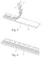
- Fig. 3
- ein Basisprofil, in das Einlegestützteile eingelegt werden;
- Fig. 4
- ein Basisprofil mit eingelegten Einlegestützteilen;
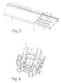
- Fig. 5
- eine Bodenschwelle mit teilweise aufgeschobenem Abdeckprofil;
- Fig. 6
- aufgewickelte Einlegestützteile.
- Die
Figur 1 zeigt eine Bodenschwelle 1 mit einem Basisprofil 2 und einem Abdeckprofil 3. Zwischen dem Basisprofil 2 und dem Abdeckprofil 3 ist ein Einlegestützteil 4 angeordnet, welches später noch näher beschrieben werden wird. Das Einlegestützteil 4 ist quer zur Längsrichtung der Bodenschwelle 1 ausgerichtet, so dass Wasser, das durch Entwässerungslöcher oder -schlitze im Abdeckprofil in die Bodenschwelle eingedrungen ist, parallel zum Einlegestützteil 4 abfließen kann, wie dies durch die Pfeile 5, 6 angedeutet ist. Das Abfließen des Wassers wird dadurch erleichtert, dass das Basisprofil 2 einen Abschnitt 2.1 aufweist, der geneigt zur Horizontalen ausgerichtet ist. Um diese Neigung auszugleichen, ist das Einlegestützteil 4 zumindest in einem Abschnitt keilförmig ausgebildet, so dass das Abdeckprofil 3 eine ebene, horizontal ausgerichtete Fläche 7 aufweist. - Die Entwässerung des Basisprofils 2 kann an einer Stelle 8 erfolgen, indem eine entsprechende Bohrung eingebracht wird. Hier könnte auch ein Entwässerungsschlauch angeschlossen werden.
- Die
Figur 2 zeigt das Einlegestützteil 4 in einer perspektivischen Ansicht. Das Einlegestützteil 4 ist mit zwei Abstandshaltern 10, 11, die in deren Längsrichtung gesehen starr, jedoch biegeelastisch sind, versehen. Insbesondere ist das Einlegestützteil 4 mit den Abstandshaltern 10, 11 einstückig verbunden. Das Einlegestützteil 4 kann zusammen mit den Abstandshaltern 10, 11 in einem Spritzgußverfahren hergestellt werden. Die Abstandshalter 10, 11 weisen an ihren freien Enden Rastköpfe 12, 13 auf, mit denen sie mit einem weiteren Einlegestützteil 4 verrastet werden können. Zu diesem Zweck weist auch das Einlegestützteil 4 Rastaufnahmen 14, 15 auf. Es ist zu erkennen, dass die Rastaufnahmen 14, 15 bolzenartige Elemente 16, 17 aufweisen. Wenn demnach an den Rastaufnahmen 14, 15 Rastköpfe 12, 13 befestigt werden, ist eine gewisse Schwenkbewegung um die Elemente 16, 17 möglich, was ein Aufwickeln mehrerer verbundener Einlegestützteile 4 erleichtert. Durch die Abstandshalter 10, 11 wird ein definierter Abstand zwischen zwei benachbarten Einlegestützteilen 4 festgelegt. - Aus der
Figur 3 ergibt sich, das mehrere Einlegestützteile 4 über die Abstandshalter 10, 11 miteinander verbunden, insbesondere verrastet, sein können. Insbesondere können mehrere Einlegestützteile 4 nach Art einer Kette miteinander verbunden sein. Dadurch erleichtert sich die Herstellung der Bodenschwelle. Die miteinander verbundenen Einlegestützteile 4 können abgerollt werden und dadurch in das wannenartige Basisprofil 2 eingelegt werden. DerFigur 3 kann man entnehmen, dass das Basisprofil 2 auf seiner Oberseite keine Längsstege (außer am vorderen und hinteren Ende) aufweist. Wasser kann demnach zwischen den Einlegestützteilen 4 zum tiefsten Punkt des Basisprofils 2 ungehindert abfließen. Für die Entwässerung können in dem vorderen Längssteg 20 hier nicht dargestellt Entwässerungsöffnungen vorgesehen sein. - Ausweislich der
Figur 4 sind die Einlegestützteile 4 vollständig in das Basisprofil 2 eingelegt. Anschließend kann das Abdeckprofil 3 angebracht werden, wie dies in derFigur 5 zu sehen ist. Nach dem Einlegen der Einlegestützteile 4 kann das Abdeckprofil 3 auf das Basisprofil 2 aufgeklipst oder aufgeschoben werden. Das Abdeckprofil 2 kann sich über die Einlegestützteile 4 am Basisprofil 2 abstützen. - Vorzugsweise sind die Abstandshalter 10, 11 mit ihrer Oberseite bündig mit der Oberseite der Einlegestützteile 4, so dass auch dadurch noch eine zusätzliche Unterstützung des Abdeckprofils 3 stattfindet.
- Die Abstandshalter 10, 11 gewährleisten immer den gleichen Abstand der Einlegestützteile 4 zueinander. Sie können auch entfallen, wenn die Einlegestützteile 4 an Bändern in dem gleichen Abstand zueinander aufgereiht werden. Die Einlegestützteile 4 können wie Ketten aufgerollt werden, um platzsparend gelagert und transportiert werden zu können. Die Einlegestützteile 4 übernehmen die Aufgabe der Lastabtragung über ihre Wandstärken in Querrichtung der Schwellenlänge.
- Der
Figur 6 kann man entnehmen, wie mehrere Einlegestützteile 4, die über die Abstandshalter 10, 11 miteinander verbunden sind, aufgerollt werden können. Hier kann man auch erkennen, dass die Abstandshalter 10, 11 biegeelastisch sind. Weiterhin kann man hier auch sehen, dass die Einlegestützteile 4 einen im Wesentlichen U-förmigen Querschnitt haben. Somit kann bei Verwendung von relativ wenig Material eine große Stabilität der Einlegestützteile 4 erreicht werden.
Claims (15)
- Bodenschwelle (1), insbesondere für eine Schiebetür oder ein Schiebefenster, mit einem Basisprofil (2) und einem Abdeckprofil (3), dadurch gekennzeichnet, dass zwischen dem Basisprofil (2) und dem Abdeckprofil (3) mehrere Einlegestützteile (4) angeordnet sind, die quer zur Längsrichtung der Bodenschwelle (1) ausgerichtet sind und das Abdeckprofil (3) abstützen.
- Bodenschwelle nach Anspruch 1, dadurch gekennzeichnet, dass die Einlegestützteile (4) einen definierten Abstand zueinander aufweisen.
- Bodenschwelle nach einem der vorhergehenden Ansprüche, dadurch gekennzeichnet, dass benachbarte Einlegestützteile (4) durch zumindest einen Abstandshalter (10, 11) beabstandet sind.
- Bodenschwelle nach einem der vorhergehenden Ansprüche, dadurch gekennzeichnet, dass zumindest zwei Einlegestützteile (4) miteinander verbunden sind.
- Bodenschwelle nach einem der vorhergehenden Ansprüche, dadurch gekennzeichnet, dass zumindest zwei Einlegestützteile (4) lösbar miteinander verbunden sind.
- Bodenschwelle nach einem der vorhergehenden Ansprüche, dadurch gekennzeichnet, dass zumindest ein Abstandshalter (10, 11) fest mit einem ersten Einlegestützteil (4) verbunden ist und mit einem zweiten Einlegestützteil (4) verrastet ist.
- Bodenschwelle nach einem der vorhergehenden Ansprüche, dadurch gekennzeichnet, dass die Einlegestützeile (4) durch flexible Verbindungselemente verbunden sind.
- Bodenschwelle nach Anspruch 7, dadurch gekennzeichnet, dass die Einlegestützteile (4) durch ein Band oder Seil miteinander verbunden sind.
- Bodenschwelle nach einem der vorhergehenden Ansprüche, dadurch gekennzeichnet, dass die Einlegestützteile (4) durch ein Filmscharnier miteinander verbunden sind.
- Bodenschwelle nach einem der vorhergehenden Ansprüche, dadurch gekennzeichnet, dass der zumindest eine Abstandshalter (10, 11) biegeelastisch ist.
- Bodenschwelle nach einem der vorhergehenden Ansprüche, dadurch gekennzeichnet, dass die miteinander verbundenen Einlegestützteile (4) aufwickelbar sind.
- Bodenschwelle nach einem der vorhergehenden Ansprüche, dadurch gekennzeichnet, dass das Basisprofil (2) wannenartig ohne Zwischenwände ausgebildet ist.
- Bodenschwelle nach einem der vorhergehenden Ansprüche, dadurch gekennzeichnet, dass zumindest eine Laufschiene für einen Schiebeflügel auf das Abdeckprofil (3) aufgesetzt ist und mit dem Abdeckprofil (3) und zumindest einem darunter angeordneten Einlegestützteil (4) verschraubt ist.
- Bodenschwelle nach einem der vorhergehenden Ansprüche, dadurch gekennzeichnet, dass das Basisprofil (2) zumindest eine Öffnung aufweist, an die ein Entwässerungsschlauch anschließbar ist.
- Bodenschwelle nach einem der vorhergehenden Ansprüche, dadurch gekennzeichnet, dass das Basisprofil (2) und/oder das Abdeckprofil (3) extrudiert oder pultrudiert sind.
Priority Applications (5)
| Application Number | Priority Date | Filing Date | Title |
|---|---|---|---|
| PL14160195T PL2921631T3 (pl) | 2014-03-17 | 2014-03-17 | Próg podłogowy |
| EP14160195.5A EP2921631B1 (de) | 2014-03-17 | 2014-03-17 | Bodenschwelle |
| ES14160195.5T ES2654089T3 (es) | 2014-03-17 | 2014-03-17 | Travesaño de suelos |
| PCT/EP2015/053259 WO2015139901A1 (de) | 2014-03-17 | 2015-02-17 | Bodenschwelle |
| CN201580013938.XA CN106103878B (zh) | 2014-03-17 | 2015-02-17 | 底槛 |
Applications Claiming Priority (1)
| Application Number | Priority Date | Filing Date | Title |
|---|---|---|---|
| EP14160195.5A EP2921631B1 (de) | 2014-03-17 | 2014-03-17 | Bodenschwelle |
Publications (2)
| Publication Number | Publication Date |
|---|---|
| EP2921631A1 true EP2921631A1 (de) | 2015-09-23 |
| EP2921631B1 EP2921631B1 (de) | 2017-09-27 |
Family
ID=50289469
Family Applications (1)
| Application Number | Title | Priority Date | Filing Date |
|---|---|---|---|
| EP14160195.5A Active EP2921631B1 (de) | 2014-03-17 | 2014-03-17 | Bodenschwelle |
Country Status (5)
| Country | Link |
|---|---|
| EP (1) | EP2921631B1 (de) |
| CN (1) | CN106103878B (de) |
| ES (1) | ES2654089T3 (de) |
| PL (1) | PL2921631T3 (de) |
| WO (1) | WO2015139901A1 (de) |
Families Citing this family (2)
| Publication number | Priority date | Publication date | Assignee | Title |
|---|---|---|---|---|
| DE102016105941A1 (de) * | 2016-03-31 | 2017-10-05 | Hautau Gmbh | Bodenschwelle für eine Schiebetür und Schiebetür |
| DE202017001325U1 (de) * | 2017-03-13 | 2017-03-31 | Siegenia-Aubi Kg | Bodenschwellensystem für einen verschiebbaren Flügel als Schiebeflügel oder verschiebaren Hebe-Schiebeflügel eines Fensters oder einer Tür |
Citations (4)
| Publication number | Priority date | Publication date | Assignee | Title |
|---|---|---|---|---|
| GB2061360A (en) * | 1979-10-24 | 1981-05-13 | Allport B C | Door sill |
| GB2297112A (en) | 1995-01-13 | 1996-07-24 | Kevin Barrett | Self-draining threshold weather excluder |
| US20060260213A1 (en) * | 2005-04-13 | 2006-11-23 | Williams Mark F | Pan flashing with sill wedge |
| US20120297712A1 (en) * | 2011-05-27 | 2012-11-29 | Jeffrey Lutzner | In-Floor Track Assembly for Sliding Panels with Built-In Drainage System |
Family Cites Families (2)
| Publication number | Priority date | Publication date | Assignee | Title |
|---|---|---|---|---|
| CN202689815U (zh) * | 2012-05-28 | 2013-01-23 | 必凯威(北京)建筑材料有限公司 | 门用断热门槛 |
| CN203271441U (zh) * | 2013-05-14 | 2013-11-06 | 山东鑫海新材料股份有限公司 | 一种门槛 |
-
2014
- 2014-03-17 PL PL14160195T patent/PL2921631T3/pl unknown
- 2014-03-17 ES ES14160195.5T patent/ES2654089T3/es active Active
- 2014-03-17 EP EP14160195.5A patent/EP2921631B1/de active Active
-
2015
- 2015-02-17 WO PCT/EP2015/053259 patent/WO2015139901A1/de not_active Ceased
- 2015-02-17 CN CN201580013938.XA patent/CN106103878B/zh not_active Expired - Fee Related
Patent Citations (4)
| Publication number | Priority date | Publication date | Assignee | Title |
|---|---|---|---|---|
| GB2061360A (en) * | 1979-10-24 | 1981-05-13 | Allport B C | Door sill |
| GB2297112A (en) | 1995-01-13 | 1996-07-24 | Kevin Barrett | Self-draining threshold weather excluder |
| US20060260213A1 (en) * | 2005-04-13 | 2006-11-23 | Williams Mark F | Pan flashing with sill wedge |
| US20120297712A1 (en) * | 2011-05-27 | 2012-11-29 | Jeffrey Lutzner | In-Floor Track Assembly for Sliding Panels with Built-In Drainage System |
Also Published As
| Publication number | Publication date |
|---|---|
| WO2015139901A1 (de) | 2015-09-24 |
| EP2921631B1 (de) | 2017-09-27 |
| ES2654089T3 (es) | 2018-02-12 |
| CN106103878A (zh) | 2016-11-09 |
| CN106103878B (zh) | 2017-11-28 |
| PL2921631T3 (pl) | 2018-02-28 |
Similar Documents
| Publication | Publication Date | Title |
|---|---|---|
| EP3319838B1 (de) | Dachreling für ein kraftfahrzeug, kraftfahrzeug mit dachreling sowie verfahren zur herstellung einer dachreling | |
| EP2631414B1 (de) | Führungsschiene für Senkrechtmarkise und Senkrechtmarkise | |
| EP2228295B1 (de) | Rollenbahn | |
| EP2921631B1 (de) | Bodenschwelle | |
| AT512327B1 (de) | Hebe/schiebetür | |
| DE102014102626A1 (de) | Kettenglied für eine Energieführungskette | |
| DE202010018232U1 (de) | Rollladenkasten | |
| DE3202385A1 (de) | Abdeckung fuer kanaele, rinnen, schaechte od. dgl. | |
| DE19501689C2 (de) | Ausziehleiter | |
| DE102008008407B3 (de) | Ballspieltor | |
| DE4023426A1 (de) | Trittleiter | |
| DE202010010684U1 (de) | Spannrahmen | |
| DE102015100523A1 (de) | Pfosten-Riegel-Konstruktion | |
| DE102006045776B4 (de) | Befestigungselement | |
| DE29816307U1 (de) | Rollabdeckung | |
| DE202017102916U1 (de) | Profilelement zur lastübertragenden Verbindung mit einer Abschattungseinrichtung und mit einem integrierten Zugelement | |
| DE29608973U1 (de) | Kunststoffprofilschiene für einen Garagentorantrieb | |
| DE102006050462B4 (de) | Isolator für einen Elektrozaun | |
| DE202004002872U1 (de) | Leiter | |
| DE29615872U1 (de) | Insektenschutz-Rollo | |
| EP2878750B1 (de) | Adapter zur aufnahme eines rollwagens eines schiebeflügels | |
| EP2382363A1 (de) | Vorrichtung zur halterung von seilschlaufen | |
| AT502331A1 (de) | Verriegelungsleiste für planenaufbauten | |
| DE29902390U1 (de) | Profil | |
| DE202019006166U1 (de) | Umlenkvorrichtung |
Legal Events
| Date | Code | Title | Description |
|---|---|---|---|
| PUAI | Public reference made under article 153(3) epc to a published international application that has entered the european phase |
Free format text: ORIGINAL CODE: 0009012 |
|
| AK | Designated contracting states |
Kind code of ref document: A1 Designated state(s): AL AT BE BG CH CY CZ DE DK EE ES FI FR GB GR HR HU IE IS IT LI LT LU LV MC MK MT NL NO PL PT RO RS SE SI SK SM TR |
|
| AX | Request for extension of the european patent |
Extension state: BA ME |
|
| 17P | Request for examination filed |
Effective date: 20151001 |
|
| RBV | Designated contracting states (corrected) |
Designated state(s): AL AT BE BG CH CY CZ DE DK EE ES FI FR GB GR HR HU IE IS IT LI LT LU LV MC MK MT NL NO PL PT RO RS SE SI SK SM TR |
|
| RIN1 | Information on inventor provided before grant (corrected) |
Inventor name: PFEIFFER, ULRICH Inventor name: NOLTING, FRANK |
|
| GRAP | Despatch of communication of intention to grant a patent |
Free format text: ORIGINAL CODE: EPIDOSNIGR1 |
|
| INTG | Intention to grant announced |
Effective date: 20170424 |
|
| GRAS | Grant fee paid |
Free format text: ORIGINAL CODE: EPIDOSNIGR3 |
|
| GRAA | (expected) grant |
Free format text: ORIGINAL CODE: 0009210 |
|
| AK | Designated contracting states |
Kind code of ref document: B1 Designated state(s): AL AT BE BG CH CY CZ DE DK EE ES FI FR GB GR HR HU IE IS IT LI LT LU LV MC MK MT NL NO PL PT RO RS SE SI SK SM TR |
|
| REG | Reference to a national code |
Ref country code: GB Ref legal event code: FG4D Free format text: NOT ENGLISH |
|
| REG | Reference to a national code |
Ref country code: CH Ref legal event code: EP |
|
| REG | Reference to a national code |
Ref country code: AT Ref legal event code: REF Ref document number: 932130 Country of ref document: AT Kind code of ref document: T Effective date: 20171015 |
|
| REG | Reference to a national code |
Ref country code: IE Ref legal event code: FG4D Free format text: LANGUAGE OF EP DOCUMENT: GERMAN |
|
| REG | Reference to a national code |
Ref country code: DE Ref legal event code: R096 Ref document number: 502014005560 Country of ref document: DE |
|
| PG25 | Lapsed in a contracting state [announced via postgrant information from national office to epo] |
Ref country code: NO Free format text: LAPSE BECAUSE OF FAILURE TO SUBMIT A TRANSLATION OF THE DESCRIPTION OR TO PAY THE FEE WITHIN THE PRESCRIBED TIME-LIMIT Effective date: 20171227 Ref country code: LT Free format text: LAPSE BECAUSE OF FAILURE TO SUBMIT A TRANSLATION OF THE DESCRIPTION OR TO PAY THE FEE WITHIN THE PRESCRIBED TIME-LIMIT Effective date: 20170927 Ref country code: SE Free format text: LAPSE BECAUSE OF FAILURE TO SUBMIT A TRANSLATION OF THE DESCRIPTION OR TO PAY THE FEE WITHIN THE PRESCRIBED TIME-LIMIT Effective date: 20170927 Ref country code: FI Free format text: LAPSE BECAUSE OF FAILURE TO SUBMIT A TRANSLATION OF THE DESCRIPTION OR TO PAY THE FEE WITHIN THE PRESCRIBED TIME-LIMIT Effective date: 20170927 Ref country code: HR Free format text: LAPSE BECAUSE OF FAILURE TO SUBMIT A TRANSLATION OF THE DESCRIPTION OR TO PAY THE FEE WITHIN THE PRESCRIBED TIME-LIMIT Effective date: 20170927 |
|
| REG | Reference to a national code |
Ref country code: NL Ref legal event code: MP Effective date: 20170927 |
|
| REG | Reference to a national code |
Ref country code: ES Ref legal event code: FG2A Ref document number: 2654089 Country of ref document: ES Kind code of ref document: T3 Effective date: 20180212 Ref country code: LT Ref legal event code: MG4D |
|
| PG25 | Lapsed in a contracting state [announced via postgrant information from national office to epo] |
Ref country code: GR Free format text: LAPSE BECAUSE OF FAILURE TO SUBMIT A TRANSLATION OF THE DESCRIPTION OR TO PAY THE FEE WITHIN THE PRESCRIBED TIME-LIMIT Effective date: 20171228 Ref country code: LV Free format text: LAPSE BECAUSE OF FAILURE TO SUBMIT A TRANSLATION OF THE DESCRIPTION OR TO PAY THE FEE WITHIN THE PRESCRIBED TIME-LIMIT Effective date: 20170927 Ref country code: BG Free format text: LAPSE BECAUSE OF FAILURE TO SUBMIT A TRANSLATION OF THE DESCRIPTION OR TO PAY THE FEE WITHIN THE PRESCRIBED TIME-LIMIT Effective date: 20171227 Ref country code: RS Free format text: LAPSE BECAUSE OF FAILURE TO SUBMIT A TRANSLATION OF THE DESCRIPTION OR TO PAY THE FEE WITHIN THE PRESCRIBED TIME-LIMIT Effective date: 20170927 |
|
| REG | Reference to a national code |
Ref country code: FR Ref legal event code: PLFP Year of fee payment: 5 |
|
| PG25 | Lapsed in a contracting state [announced via postgrant information from national office to epo] |
Ref country code: NL Free format text: LAPSE BECAUSE OF FAILURE TO SUBMIT A TRANSLATION OF THE DESCRIPTION OR TO PAY THE FEE WITHIN THE PRESCRIBED TIME-LIMIT Effective date: 20170927 |
|
| PG25 | Lapsed in a contracting state [announced via postgrant information from national office to epo] |
Ref country code: RO Free format text: LAPSE BECAUSE OF FAILURE TO SUBMIT A TRANSLATION OF THE DESCRIPTION OR TO PAY THE FEE WITHIN THE PRESCRIBED TIME-LIMIT Effective date: 20170927 Ref country code: CZ Free format text: LAPSE BECAUSE OF FAILURE TO SUBMIT A TRANSLATION OF THE DESCRIPTION OR TO PAY THE FEE WITHIN THE PRESCRIBED TIME-LIMIT Effective date: 20170927 |
|
| PG25 | Lapsed in a contracting state [announced via postgrant information from national office to epo] |
Ref country code: SK Free format text: LAPSE BECAUSE OF FAILURE TO SUBMIT A TRANSLATION OF THE DESCRIPTION OR TO PAY THE FEE WITHIN THE PRESCRIBED TIME-LIMIT Effective date: 20170927 Ref country code: IS Free format text: LAPSE BECAUSE OF FAILURE TO SUBMIT A TRANSLATION OF THE DESCRIPTION OR TO PAY THE FEE WITHIN THE PRESCRIBED TIME-LIMIT Effective date: 20180127 Ref country code: SM Free format text: LAPSE BECAUSE OF FAILURE TO SUBMIT A TRANSLATION OF THE DESCRIPTION OR TO PAY THE FEE WITHIN THE PRESCRIBED TIME-LIMIT Effective date: 20170927 Ref country code: EE Free format text: LAPSE BECAUSE OF FAILURE TO SUBMIT A TRANSLATION OF THE DESCRIPTION OR TO PAY THE FEE WITHIN THE PRESCRIBED TIME-LIMIT Effective date: 20170927 |
|
| REG | Reference to a national code |
Ref country code: DE Ref legal event code: R097 Ref document number: 502014005560 Country of ref document: DE |
|
| PG25 | Lapsed in a contracting state [announced via postgrant information from national office to epo] |
Ref country code: DK Free format text: LAPSE BECAUSE OF FAILURE TO SUBMIT A TRANSLATION OF THE DESCRIPTION OR TO PAY THE FEE WITHIN THE PRESCRIBED TIME-LIMIT Effective date: 20170927 |
|
| PLBE | No opposition filed within time limit |
Free format text: ORIGINAL CODE: 0009261 |
|
| STAA | Information on the status of an ep patent application or granted ep patent |
Free format text: STATUS: NO OPPOSITION FILED WITHIN TIME LIMIT |
|
| 26N | No opposition filed |
Effective date: 20180628 |
|
| PG25 | Lapsed in a contracting state [announced via postgrant information from national office to epo] |
Ref country code: MT Free format text: LAPSE BECAUSE OF FAILURE TO SUBMIT A TRANSLATION OF THE DESCRIPTION OR TO PAY THE FEE WITHIN THE PRESCRIBED TIME-LIMIT Effective date: 20170927 |
|
| REG | Reference to a national code |
Ref country code: CH Ref legal event code: PL |
|
| PG25 | Lapsed in a contracting state [announced via postgrant information from national office to epo] |
Ref country code: SI Free format text: LAPSE BECAUSE OF FAILURE TO SUBMIT A TRANSLATION OF THE DESCRIPTION OR TO PAY THE FEE WITHIN THE PRESCRIBED TIME-LIMIT Effective date: 20170927 Ref country code: MC Free format text: LAPSE BECAUSE OF FAILURE TO SUBMIT A TRANSLATION OF THE DESCRIPTION OR TO PAY THE FEE WITHIN THE PRESCRIBED TIME-LIMIT Effective date: 20170927 |
|
| REG | Reference to a national code |
Ref country code: BE Ref legal event code: MM Effective date: 20180331 |
|
| REG | Reference to a national code |
Ref country code: IE Ref legal event code: MM4A |
|
| PG25 | Lapsed in a contracting state [announced via postgrant information from national office to epo] |
Ref country code: LU Free format text: LAPSE BECAUSE OF NON-PAYMENT OF DUE FEES Effective date: 20180317 |
|
| PG25 | Lapsed in a contracting state [announced via postgrant information from national office to epo] |
Ref country code: IE Free format text: LAPSE BECAUSE OF NON-PAYMENT OF DUE FEES Effective date: 20180317 |
|
| PG25 | Lapsed in a contracting state [announced via postgrant information from national office to epo] |
Ref country code: IT Free format text: LAPSE BECAUSE OF NON-PAYMENT OF DUE FEES Effective date: 20180317 Ref country code: BE Free format text: LAPSE BECAUSE OF NON-PAYMENT OF DUE FEES Effective date: 20180331 Ref country code: CH Free format text: LAPSE BECAUSE OF NON-PAYMENT OF DUE FEES Effective date: 20180331 Ref country code: LI Free format text: LAPSE BECAUSE OF NON-PAYMENT OF DUE FEES Effective date: 20180331 |
|
| PGFP | Annual fee paid to national office [announced via postgrant information from national office to epo] |
Ref country code: GB Payment date: 20200325 Year of fee payment: 7 |
|
| PG25 | Lapsed in a contracting state [announced via postgrant information from national office to epo] |
Ref country code: PT Free format text: LAPSE BECAUSE OF FAILURE TO SUBMIT A TRANSLATION OF THE DESCRIPTION OR TO PAY THE FEE WITHIN THE PRESCRIBED TIME-LIMIT Effective date: 20170927 |
|
| PG25 | Lapsed in a contracting state [announced via postgrant information from national office to epo] |
Ref country code: CY Free format text: LAPSE BECAUSE OF FAILURE TO SUBMIT A TRANSLATION OF THE DESCRIPTION OR TO PAY THE FEE WITHIN THE PRESCRIBED TIME-LIMIT Effective date: 20170927 Ref country code: HU Free format text: LAPSE BECAUSE OF FAILURE TO SUBMIT A TRANSLATION OF THE DESCRIPTION OR TO PAY THE FEE WITHIN THE PRESCRIBED TIME-LIMIT; INVALID AB INITIO Effective date: 20140317 Ref country code: MK Free format text: LAPSE BECAUSE OF NON-PAYMENT OF DUE FEES Effective date: 20170927 |
|
| PG25 | Lapsed in a contracting state [announced via postgrant information from national office to epo] |
Ref country code: AL Free format text: LAPSE BECAUSE OF FAILURE TO SUBMIT A TRANSLATION OF THE DESCRIPTION OR TO PAY THE FEE WITHIN THE PRESCRIBED TIME-LIMIT Effective date: 20170927 |
|
| GBPC | Gb: european patent ceased through non-payment of renewal fee |
Effective date: 20210317 |
|
| PG25 | Lapsed in a contracting state [announced via postgrant information from national office to epo] |
Ref country code: GB Free format text: LAPSE BECAUSE OF NON-PAYMENT OF DUE FEES Effective date: 20210317 |
|
| PGFP | Annual fee paid to national office [announced via postgrant information from national office to epo] |
Ref country code: AT Payment date: 20220318 Year of fee payment: 9 |
|
| REG | Reference to a national code |
Ref country code: AT Ref legal event code: MM01 Ref document number: 932130 Country of ref document: AT Kind code of ref document: T Effective date: 20230317 |
|
| PG25 | Lapsed in a contracting state [announced via postgrant information from national office to epo] |
Ref country code: AT Free format text: LAPSE BECAUSE OF NON-PAYMENT OF DUE FEES Effective date: 20230317 |
|
| PGFP | Annual fee paid to national office [announced via postgrant information from national office to epo] |
Ref country code: ES Payment date: 20250416 Year of fee payment: 12 |
|
| PGFP | Annual fee paid to national office [announced via postgrant information from national office to epo] |
Ref country code: DE Payment date: 20260320 Year of fee payment: 13 |
|
| PGFP | Annual fee paid to national office [announced via postgrant information from national office to epo] |
Ref country code: FR Payment date: 20260325 Year of fee payment: 13 |
|
| PGFP | Annual fee paid to national office [announced via postgrant information from national office to epo] |
Ref country code: TR Payment date: 20260309 Year of fee payment: 13 |
|
| PGFP | Annual fee paid to national office [announced via postgrant information from national office to epo] |
Ref country code: PL Payment date: 20260304 Year of fee payment: 13 |