EP2921075B1 - Tisch- oder Geräteplattenanchlussfeld - Google Patents
Tisch- oder Geräteplattenanchlussfeld Download PDFInfo
- Publication number
- EP2921075B1 EP2921075B1 EP15157319.3A EP15157319A EP2921075B1 EP 2921075 B1 EP2921075 B1 EP 2921075B1 EP 15157319 A EP15157319 A EP 15157319A EP 2921075 B1 EP2921075 B1 EP 2921075B1
- Authority
- EP
- European Patent Office
- Prior art keywords
- ribs
- figur
- device plate
- connection field
- bracing elements
- Prior art date
- Legal status (The legal status is an assumption and is not a legal conclusion. Google has not performed a legal analysis and makes no representation as to the accuracy of the status listed.)
- Active
Links
Images


Classifications
-
- H—ELECTRICITY
- H01—ELECTRIC ELEMENTS
- H01R—ELECTRICALLY-CONDUCTIVE CONNECTIONS; STRUCTURAL ASSOCIATIONS OF A PLURALITY OF MUTUALLY-INSULATED ELECTRICAL CONNECTING ELEMENTS; COUPLING DEVICES; CURRENT COLLECTORS
- H01R25/00—Coupling parts adapted for simultaneous co-operation with two or more identical counterparts, e.g. for distributing energy to two or more circuits
- H01R25/006—Coupling parts adapted for simultaneous co-operation with two or more identical counterparts, e.g. for distributing energy to two or more circuits the coupling part being secured to apparatus or structure, e.g. duplex wall receptacle
-
- A—HUMAN NECESSITIES
- A47—FURNITURE; DOMESTIC ARTICLES OR APPLIANCES; COFFEE MILLS; SPICE MILLS; SUCTION CLEANERS IN GENERAL
- A47B—TABLES; DESKS; OFFICE FURNITURE; CABINETS; DRAWERS; GENERAL DETAILS OF FURNITURE
- A47B21/00—Tables or desks for office equipment, e.g. typewriters, keyboards
- A47B21/06—Tables or desks for office equipment, e.g. typewriters, keyboards characterised by means for holding, fastening or concealing cables
- A47B2021/066—Tables or desks for office equipment, e.g. typewriters, keyboards characterised by means for holding, fastening or concealing cables with power or communication connection interface
-
- H—ELECTRICITY
- H02—GENERATION; CONVERSION OR DISTRIBUTION OF ELECTRIC POWER
- H02G—INSTALLATION OF ELECTRIC CABLES OR LINES, OR OF COMBINED OPTICAL AND ELECTRIC CABLES OR LINES
- H02G3/00—Installations of electric cables or lines or protective tubing therefor in or on buildings, equivalent structures or vehicles
- H02G3/02—Details
- H02G3/08—Distribution boxes; Connection or junction boxes
- H02G3/12—Distribution boxes; Connection or junction boxes for flush mounting
- H02G3/123—Distribution boxes; Connection or junction boxes for flush mounting in thin walls
Definitions
- the invention relates to a table or device plate connection panel for mains voltage connections and / or information terminals, with a housing which is provided with a collar and fastening means, wherein a socket insert is provided with slots, wherein the fastening means are formed by ribs, which on two opposite sides of the housing are provided and are aligned at an angle of 5 ° to the horizontal, and that the ribs correspond with bracing elements.
- Table or device plate connection fields are known in many ways. They provide the mains voltage and / or the information supply for mobile data devices and other power consumers.
- the known devices are arranged in a table or device plate or a floor.
- the connection panels can be opened to connect the consumers. When unfolding the mains voltage and information connections are exposed from the plate or the floor and are thus visible.
- the connections can be used in this position for plugging in the plugs of the data devices and / or power consumers.
- Table or device plate connection fields are also from the DE 24 30 707 A1 and WO 2010/037390 A2 known in which fasteners with ribs or locking devices are described.
- the invention aims to remedy this situation.
- the invention has for its object to provide a table or device plate connection panel for mains voltage connections and / or information terminals, which is easy and at the same time reliably mounted.
- a table or device plate connection field for mains voltage connections and / or information connections is created, which is easy and at the same time reliably mounted. This is caused by the fact that due to the correspondence between the arranged on the housing at an angle ribs and the bracing elements, a clamping action is caused, which holds the terminal pads stationary in the plates or the floor. Experiments have shown that the angle of 5 ° for a jamming is particularly suitable.
- the ribs are provided on the two end sides of the housing.
- This embodiment has the advantage that the paths for the clamping of the connection field is relatively short, so that the bracing elements have only small dimensions. This leads on the one hand to improved handling, on the other hand, the cost is reduced.
- the ribs are provided with grooves.
- the grooves provide an improved clamping effect, giving the attachment additional stability.
- the ribs are mounted at an angle and provided the bracing elements on at least one of its longitudinal sides with a fold.
- the angle of attack in correspondence with the fold leads to the possibility of allowing the fastening device to be loosened by simply tilting the bracing elements in the direction away from the respective end face.
- a fast solubility is ensured, which does not adversely affect the stability.
- the bracing elements on projections.
- the projections correspond to the grooves in the ribs and thus cause a toothing during clamping of the bracing elements with the ribs. Thus, an additional security against automatic release of the fastening device is prevented.
- the table or device plate connection field for mains voltage connections and / or for information connections chosen as an exemplary embodiment comprises a housing 1 in which a socket insert 2 is arranged.
- the housing 1 is provided with a collar 3, which rests in the assembled state of the connection field on the table or device plate or the floor.
- the collar 3 covers in the assembled state provided for receiving the connection panel in the plate or the floor opening.
- the housing 1 has a trough-like shape. It is provided in the embodiment at its end faces with fasteners 4, with which a reliable attachment of the connection pad on the table or device plate or the floor can be done.
- the fastening devices 4 are formed by ribs 41, which are provided on two opposite sides of the housing 4.
- the ribs 41 are provided on the end sides of the housing 4.
- the ribs 41 are aligned at an angle to the horizontal. According to the invention, the angle is 5 ° to the horizontal.
- the ribs 41 are mounted at an angle of attack on the end faces, wherein the angle in the exemplary embodiment is 45 °.
- the ribs 41 are provided with grooves 42.
- the ribs 41 correspond to bracing elements 45, which are wedge-shaped.
- the bracing elements 45 are provided on at least one of their longitudinal sides with a fold 46, which is oriented at an angle of 45 ° and therefore corresponds to the angle of attack of the ribs 41.
- the bends 46 have projections 47, which are tuned in type and orientation to the grooves 42 of the ribs 41.
- the bracing elements 45 are provided with a smooth clamping surface 48.
- the bracing elements 45 are provided on their two longitudinal sides with folds 46. It is thus possible, with a bracing element 45 two adjacent to each other arranged table or device plate connection panels with a bracing 45 to attach.
- the bracing elements 45 provided for fastening a tabletop or device panel connection field are connected to one another by a bridge 49, so that a type of frame is formed which surrounds the respective tabletop or device panel connection field on three sides after fastening.
- the housing 1 On its side facing away from the collar 3, the housing 1 is provided with slots 5.
- the slots 5 allow the outflow of liquids entering the housing 1. Likewise, for example, when installing the connection field according to the invention in a kitchen, it is possible to remove crumbs or the like from the housing 1.
- the collar 3 has on its the floor or the table or device plate side facing an undercut 6.
- the undercut 6 is suitable for receiving a seal (not shown), so that additional security is provided against the penetration of liquids pouring out of the plate or the floor.
- the socket insert 2 is provided with slots 7.
- the slots are in the embodiment to two sockets for mains voltage connections and a slot for information connections.
- the socket insert 2 is provided with a projection 8, in which the slots 7 are arranged. Visible extends in the embodiment, the projection 8 over the entire length of the socket insert 2.
- the projection 8 has a smaller width than the socket insert 2, whereby on the longitudinal sides of the projection 8, an edge 9 is formed.
- the socket insert 2 is rotatably arranged in the housing 1 by 180 ° about its longitudinal axis.
- the provision of a smaller angle of rotation is possible to realize, for example, a user facing, slightly inclined Asked insertion.
- a Drehwinkelbe dictionary 10 is provided on the front sides of the socket set 2.
- the Drehwinkeibeskyr 10 corresponds in the closed position of the connection field with a gate 11, as shown in FIG. 5 is recognizable.
- the rotation angle limiter 10 is in the immediate vicinity of the collar 3 and thus serves as a stop, as this FIG. 10 can be seen.
- connection pad When attaching the table or device plate connection panel according to the invention this is used in a known manner in an opening provided in the table or device plate or the floor opening and is in this position with the collar 3 on the plate or the floor.
- connection pad is in a simple manner in the embodiment of the Figures 11 and 12 attached to both end faces of the connection pad a bracing 45.
- the bracing elements 45 By moving the bracing elements 45 parallel to the end faces, the bends 46 come into contact with the ribs 41.
- the clamping surface 48 of the bracing elements 45 is supported on the underside of the plate or the floor. The final fastening position is reached as soon as further displacement of the bracing elements 45 is no longer possible.
Landscapes
- Connection Of Plates (AREA)
Description
- Die Erfindung betrifft ein Tisch- oder Geräteplattenanschlussfeld für Netzspannungsanschlüsse und/oder Informationsanschlüsse, mit einem Gehäuse, das mit einem Kragen versehen ist und Befestigungseinrichtungen aufweist, wobei ein Steckdoseneinsatz mit Steckplätzen vorgesehen ist, wobei die Befestigungseinrichtungen von Rippen gebildet sind, die an zwei gegenüberliegenden Seiten des Gehäuses vorgesehen sind und unter einem Winkel von 5° zur Horizontalen ausgerichtet sind, und dass die Rippen mit Verspannungselementen korrespondieren.
- Tisch- oder Geräteplattenanschlussfelder sind in vielfältiger Weise bekannt. Sie stellen die Netzspannung und/oder die Informationsversorgung für bewegliche Datengeräte und andere Stromverbraucher bereit. Die bekannten Vorrichtungen sind in einer Tisch- oder Geräteplatte oder einem Fußboden angeordnet. Zum Anschluss der Verbraucher sind die Anschlussfelder aufklappbar. Beim Aufklappen werden die Netzspannungs- und Informationsanschlüsse aus der Platte bzw. dem Fußboden freigelegt und sind somit sichtbar. Die Anschlüsse können in dieser Position zum Einstecken der Stecker der Datengeräte und/oder Stromverbraucher genutzt werden.
- Tisch- oder Geräteplattenanschlussfelder benötigen in der Tisch- oder Geräteplatte bzw. dem Fußboden eine sichere Befestigung, um einen zuverlässigen Anschluss an die elektrische Gebäudeinstallation sowie Datenkabel erfordert. Gleichzeitig muss gewährleistet sein, dass beim Einstecken von Steckern elektrischer Verbraucher oder Datenverarbeitungsgeräten die Tisch- oder Geräteplattenanschlussfelder spielfrei in den Platten bzw. dem Fußboden angeordnet sind. Hierzu finden Befestigungsvorrichtungen in Form von Schraubverbindungen Anwendung (vgl. bspw.
DE 24 32 619 A1 oderUS 5 913 439 A ). Es sind auch Lösungen bekannt, bei denen gelochte Laschen nach dem Einsetzen der Anschlussfelder in der die jeweilige Tisch- oder Geräteplatte bzw. dem Fußboden auf der Unterseite der Platte bzw. des Bodens umgebogen werden und durch die Lochung eine Schraube in die Platte bzw. in den Fußboden eingebracht wird. Zwar ist diese Art der Befestigung zuverlässig und erfüllt somit ihren Zweck; sie weist jedoch den Nachteil auf, dass ihre Installation aufwändig ist. Insbesondere die Tatsache, dass die Befestigung auf der Unterseite der jeweiligen Platte bzw. dem Fußboden stattfindet, macht die Montage umständlich. Bei runden Gehäusen lassen sich Lösungen realisieren, die eine Drehverbindung der Teile ermöglichen (vgl. bspw.US 4 053 082 A ). - Tisch- oder Geräteplattenanschlussfelder sind auch aus der
DE 24 30 707 A1 undWO 2010/037390 A2 bekannt, bei denen Befestigungseinrichtungen mit Rippen oder Rasteinrichtungen beschrieben sind. - Hier will die Erfindung Abhilfe schaffen. Der Erfindung liegt die Aufgabe zugrunde, ein Tisch- oder Geräteplattenanschlussfeld für Netzspannungsanschlüsse und/oder Informationsanschlüsse zu schaffen, das einfach und zugleich zuverlässig montierbar ist.
- Mit der Erfindung ist ein Tisch- oder Geräteplattenanschlussfeld für Netzspannungsanschlüsse und/oder Informationsanschlüsse geschaffen, welches einfach und zugleich zuverlässig montierbar ist. Dies ist dadurch hervorgerufen, dass aufgrund der Korrespondenz zwischen den an dem Gehäuse unter einem Winkel angeordneten Rippen und den Verspannungselementen eine Klemmwirkung hervorgerufen ist, die die Anschlussfelder ortsfest in den Platten bzw. dem Fußboden hält. Versuche haben ergeben, dass der Winkel von 5° für eine Verklemmung als besonders geeignet ist.
- In Weiterbildung der Erfindung sind die Rippen an den beiden Stirnseiten des Gehäuses vorgesehen. Diese Ausgestaltung weist den Vorteil auf, dass der Wege für die Verspannung des Anschlussfeldes relativ kurz ist, so dass auch die Verspannungselemente lediglich geringe Abmessungen aufweisen. Dies führt einerseits zu einer verbesserten Handhabung, andererseits sind die Kosten dadurch reduziert.
- In anderer Weiterbildung der Erfindung sind die Rippen mit Nuten versehen. Die Nuten führen eine verbesserte Klemmwirkung herbei, wodurch die Befestigung zusätzliche Stabilität erhält.
- In vorteilhafter Weiterbildung der Erfindung sind die Rippen unter einem Anstellwinkel angebracht und die Verspannungselemente an mindestens einer ihrer Längsseiten mit einer Abkantung versehen. Hierdurch ist einerseits eine zuverlässige Korrespondenz zwischen den Rippen und den Verspannungselementen hervorgerufen. Andererseits führt der Anstellwinkel in Korrespondenz mit der Abkantung zu der Möglichkeit, ein Lösen der Befestigungseinrichtung durch einfaches Kippen der Verspannungselemente in die der jeweiligen Stirnseite abgewandte Richtung zu ermöglichen. Somit ist eine schnelle Lösbarkeit gewährleistet, welche die Stabilität nicht negativ beeinflusst.
- In anderer Ausgestaltung der Erfindung weisen die Verspannungselemente Vorsprünge auf. Die Vorsprünge korrespondieren mit den Nuten in den Rippen und rufen so eine Verzahnung beim Verspannen der Verspannungselemente mit den Rippen hervor. Somit ist eine zusätzliche Sicherheit gegen selbsttätiges Lösen der Befestigungseinrichtung verhindert.
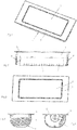
- Andere Weiterbildungen und Ausgestaltungen der Erfindung sind in den übrigen Unteransprüchen angegeben. Ausführungsbeispiele der Erfindung sind in den Zeichnungen dargestellt und werden nachfolgend im Einzelnen beschrieben. Es zeigen:
- Figur 1
- die perspektivische Darstellung eines Tisch- oder Geräteplattenanschlussfeldes in geschlossenem Zustand;
- Figur 2
- die Ansicht des in
Figur 1 dargestellten Tisch- oder Geräteplattenanschlussfeldes; - Figur 3
- die Draufsicht auf das in
Figur 1 dargestellte Tisch- oder Geräteplattenanschlussfeld; - Figur 3
- die Draufsicht auf das in
Figur 1 dargestellte Tisch- oder Geräteplattenanschlussfeld; - Figur 4
- die Seitenansicht auf das in
Figur 1 dargestellte Tisch- oder Geräteplattenanschlussfeld; - Figur 5
- die Seitenansicht auf den Steckdoseneinsatz in geschlossener Position;
- Figur 6
- die perspektivische Darstellung des in
Figur 1 dargestellten Tischoder Geräteplattenanschlussfeldes in Betriebsposition; - Figur 7
- die Ansicht des in
Figur 6 dargestellten Tisch- oder Geräteplattenanschlussfeldes; - Figur 8
- die Draufsicht auf das in
Figur 6 dargestellte Tisch- oder Geräteplattenanschlussfeld; - Figur 9
- die Seitenansicht des in
Figur 6 dargestellten Tisch- oder Geräteplattenanschlussfeldes; - Figur 10
- die Seitenansicht auf den Steckdoseneinsatz in Betriebsposition;
- Figur 11
- eine perspektivische Darstellung des in
Figur 1 dargestellten Tisch- oder Geräteplattenanschlussfeldes in geschlossenem Zustand mit Verspannungselementen; - Figur 12
- eine perspektivische Ansicht von unten des in
Figur 11 dargestellten Tisch- oder Geräteplattenanschlussfeldes mit Verspannungselementen; - Figur 13
- eine perspektivische Darstellung des in
Figur 1 dargestellten Tisch- oder Geräteplattenanschlussfeldes in geschlossenem Zustand mit Verspannungselementen in anderer Ausbildung; - Figur 14
- eine perspektivische Ansicht von unten des in
Figur 13 dargestellten Tisch- oder Geräteplattenanschlussfeldes mit Verspannungselementen; - Figur 15
- die Seitenansicht auf das in
Figur 1 dargestellte Tisch- oder Geräteplattenanschlussfeld in vergrößerter Darstellung; - Figur 16
- die Seitenansicht auf ein Verspannungselement in vergrößerter Darstellung.
- Das als Ausführungsbeispiel gewählte Tisch- oder Geräteplattenanschlussfeld für Netzspannungsanschlüsse und/oder für Informationsanschlüsse umfasst ein Gehäuse 1, in dem ein Steckdoseneinsatz 2 angeordnet ist. Das Gehäuse 1 ist mit einem Kragen 3 versehen, der in montiertem Zustand des Anschlussfeldes auf der Tisch- oder Geräteplatte bzw. dem Fußboden aufliegt. Der Kragen 3 überdeckt in montiertem Zustand die für die Aufnahme des Anschlussfeldes in der Platte oder dem Fußboden vorgesehene Öffnung.
- Das Gehäuse 1 weist eine wannenartige Form auf. Es ist im Ausführungsbeispiel an seinen Stirnseiten mit Befestigungseinrichtungen 4 versehen, mit denen eine zuverlässige Befestigung des Anschlussfeldes an der Tisch- oder Geräteplatte bzw. dem Fußboden erfolgen kann. Die Befestigungseinrichtungen 4 sind von Rippen 41 gebildet, die an zwei gegenüberliegenden Seiten des Gehäuses 4 vorgesehen sind. Im Ausführungsbeispiel sind die Rippen 41 an den Stirnseiten des Gehäuses 4 vorgesehen. Die Rippen 41 sind unter einem Winkel zur Horizontalen ausgerichtet. Erfindungsgemäss beträgt der Winkel 5° zur Horizontalen. Gleichzeitig sind die Rippen 41 unter einem Anstellwinkel an den Stirnseiten angebracht, wobei der Winkel im Ausführungsbeispiel 45° beträgt. Die Rippen 41 sind mit Nuten 42 versehen.
- Die Rippen 41 korrespondieren mit Verspannungselementen 45, die keilartig ausgebildet sind. Die Verspannungselemente 45 sind an mindestens einer ihrer Längsseiten mit einer Abkantung 46 versehen, die unter einem Winkel von 45° ausgerichtet ist und daher mit dem Anstellwinkel der Rippen 41 korrespondiert. Die Abkantungen 46 weisen Vorsprünge 47 auf, die in Art und Ausrichtung auf die Nuten 42 der Rippen 41 abgestimmt sind. Auf ihrer der Tisch- oder Geräteplatte bzw. dem Fußboden zugewandten Seite sind die Verspannungselemente 45 mit einer glatten Klemmfläche 48 versehen.
- Im Ausführungsbeispiel nach den
Figuren 11 und12 sind die Verspannungselemente 45 an ihren beiden Längsseiten mit Abkantungen 46 versehen. Es besteht so die Möglichkeit, mit einem Verspannungselement 45 zwei benachbart zueinander angeordnete Tisch- oder Geräteplattenanschlussfelder mit einem Verspannungselement 45 zu befestigen. Im Ausführungsbeispiel nach denFiguren 13 und14 sind die zur Befestigung eines Tisch- oder Geräteplattenanschlussfeldes vorgesehenen Verspannungselemente 45 durch eine Brücke 49 miteinander verbunden, so dass eine Art Rahmen ausgebildet ist, der das jeweilige Tisch- oder Geräteplattenanschlussfeld nach dem Befestigen an drei Seiten umgibt. - Auf seiner dem Kragen 3 abgewandten Seite ist das Gehäuse 1 mit Schlitzen 5 versehen. Die Schlitze 5 ermöglichen das Abfließen von in das Gehäuse 1 eintretenden Flüssigkeiten. Ebenso besteht beispielsweise beim Einbau des erfindungsgemäßen Anschlussfeldes in einer Küche die Möglichkeit, Krümel oder der gleichen aus dem Gehäuse 1 zu entfernen.
- Der Kragen 3 weist auf seiner dem Fußboden oder der Tisch- oder Geräteplatte zugewandten Seite einen Hinterschnitt 6 auf. Der Hinterschnitt 6 ist zur Aufnahme einer - nicht dargestellten - Dichtung geeignet, so dass eine zusätzliche Sicherheit gegen das Eindringen von sich über die Platte oder den Fußboden ergießenden Flüssigkeiten geschaffen ist.
- Der Steckdoseneinsatz 2 ist mit Steckplätzen 7 versehen. Bei den Steckplätzen handelt es sich im Ausführungsbeispiel um zwei Steckdosen für Netzspannungsanschlüsse und einen Steckplatz für Informationsanschlüsse. Selbstverständlich ist eine andere Verteilung und Anzahl an Steckplätzen als die im Ausführungsbeispiel gezeigte möglich. Der Steckdoseneinsatz 2 ist mit einem Vorsprung 8 versehen, in dem die Steckplätze 7 angeordnet sind. Erkennbar erstreckt sich im Ausführungsbeispiel der Vorsprung 8 über die gesamte Länge des Steckdoseneinsatzes 2. Der Vorsprung 8 weist dabei eine geringere Breite als der Steckdoseneinsatz 2 auf, wodurch an den Längsseiten des Vorsprungs 8 ein Rand 9 ausgebildet ist.
- Der Steckdoseneinsatz 2 ist in dem Gehäuse 1 um 180° um seine Längsachse drehbar angeordnet. In Abwandlung des Ausführungsbeispiels besteht die Möglichkeit, andere Drehwinkel zu ermöglichen. So besteht beispielsweise die Möglichkeit, den Steckdoseneinsatz auch um 360° drehbar auszugestalten. Auch das Vorsehen eines geringeren Drehwinkels ist möglich, um beispielsweise eine dem Benutzer zugewandte, leicht schräg gestellte Einsteckposition zu realisieren.
- Im Ausführungsbeispiel ist an den Stirnseiten des Steckdoseneisatzes 2 ein Drehwinkelbegrenzer 10 vorgesehen. Der Drehwinkeibegrenzer 10 korrespondiert in geschlossener Position des Anschlussfeldes mit einer Kulisse 11, wie dies in
Figur 5 erkennbar ist. In der betriebsbereiten Position des Anschlussfeldes befindet sich der Drehwinkelbegrenzer 10 dagegen in unmittelbarer Nähe zum Kragen 3 und dient somit als Anschlag, wie diesFigur 10 zu entnehmen ist. - Bei der Befestigung des erfindungsgemäßen Tisch- oder Geräteplattenanschlussfeldes wird dieses in bekannter Weise in eine in der Tisch- oder Geräteplatte bzw. dem Fußboden vorgesehene Öffnung eingesetzt und liegt in dieser Position mit dem Kragen 3 auf der Platte bzw. dem Fußboden auf. Zum Befestigen des Anschlussfeldes wird in einfacher Weise im Ausführungsbeispiel nach den
Figuren 11 und12 an beiden Stirnseiten des Anschlussfeldes ein Verspannungselement 45 angesetzt. Durch Verschieben der Verspannungselemente 45 parallel zu den Stirnseiten treten die Abkantungen 46 mit den Rippen 41 in Kontakt. Die Vorsprünge 47 fassen dabei hinter die Nuten 42 der Rippen 41. Gleichzeitig stützt sich die Klemmfläche 48 der Verspannungselemente 45 an der Unterseite der Platte bzw. des Fußbodens ab. Die endgültige Befestigungsposition ist erreicht, sobald ein weiteres Verschieben der Verspannungselemente 45 nicht mehr möglich ist. Durch die Kombination der Nuten 42 mit den Vorsprüngen 47 ist eine Rastverbindung geschaffen, die ein selbsttätiges Zurückrutschen der Spannungselemente 45 verhindert. Die Befestigung mit Hilfe der in den Ausführungsbeispielen nach denFiguren 13 und14 dargestellten rahmenartig ausgebildeten Verspannungselemente 45 erfolgt in gleicher Weise, wobei hierbei der Vorteil darin besteht, dass mit einer einzigen Handbewegung beide Verspannungselemente 45 gleichzeitig an den beiden Stirnseiten die Klemmwirkung hervorrufen können. - Bei der Ausgestaltung nach den
Figuren 11 und12 ist aufgrund der an den Verspannungselementen 45 vorgesehenen Abkantungen 46 zudem die Möglichkeit geschaffen, eine einfache Lösbarkeit zu erreichen. Hierzu ist es lediglich erforderlich, die Verspannungselemente 45 um ihre Längsachse in die der jeweiligen Stirnseiten abgewandte Richtung zu kippen. Dadurch werden die Abkantungen von den Rippen freigegeben, so dass das Anschlussfeld problemlos aus der Öffnung in der Platte bzw. dem Fußboden herausnehmbar ist.
Claims (5)
- Tisch- oder Geräteplattenanschlussfeld für Netzspannungsanschlüsse und/oder Informationsanschlüsse, mit einem Gehäuse (1), das mit einem Kragen (3) versehen ist und Befestigungseinrichtungen (4) aufweist, wobei ein Steckdoseneinsatz (2) mit Steckplätzen (7) vorgesehen ist, wobei die Befestigungseinrichtungen (4) von Rippen (41) gebildet sind, die an zwei gegenüberliegenden Seiten des Gehäuses (1) vorgesehen sind und unter einem Winkel von 5° zur Horizontalen ausgerichtet sind, und dass die Rippen (41) mit Verspannungselementen (45) korrespondieren, wobei die Verspannungselemente (45) keilartig ausgebildet sind.
- Anschlussfeld nach Anspruch 1, dadurch gekennzeichnet, dass die Rippen (41) an den beiden Stirnseiten des Gehäuses (1) vorgesehen sind.
- Anschlussfeld nach einem oder mehreren der vorgenannten Ansprüche, dadurch gekennzeichnet, dass die Rippen (41) mit Nuten (42) versehen sind.
- Anschlussfeld nach einem oder mehreren der vorgenannten Ansprüche, dadurch gekennzeichnet, dass die Rippen (41) unter einem Anstellwinkel angebracht sind und die Verspannungselemente (45) an mindestens einer ihrer Längsseiten mit einer Abkantung (46) versehen sind.
- Anschlussfeld nach einem oder mehreren der vorgenannten Ansprüche, dadurch gekennzeichnet, dass die Verspannungselemente (45) Vorsprünge (47) aufweisen.
Applications Claiming Priority (1)
| Application Number | Priority Date | Filing Date | Title |
|---|---|---|---|
| DE102014102961.5A DE102014102961B3 (de) | 2014-03-06 | 2014-03-06 | Tisch- oder Geräteplattenanschlussfeld |
Publications (2)
| Publication Number | Publication Date |
|---|---|
| EP2921075A1 EP2921075A1 (de) | 2015-09-23 |
| EP2921075B1 true EP2921075B1 (de) | 2019-04-10 |
Family
ID=52669458
Family Applications (1)
| Application Number | Title | Priority Date | Filing Date |
|---|---|---|---|
| EP15157319.3A Active EP2921075B1 (de) | 2014-03-06 | 2015-03-03 | Tisch- oder Geräteplattenanchlussfeld |
Country Status (2)
| Country | Link |
|---|---|
| EP (1) | EP2921075B1 (de) |
| DE (1) | DE102014102961B3 (de) |
Citations (4)
| Publication number | Priority date | Publication date | Assignee | Title |
|---|---|---|---|---|
| US4053082A (en) * | 1976-03-01 | 1977-10-11 | Unarco Industries, Inc. | Electrical outlet box assembly |
| US5913439A (en) * | 1997-08-29 | 1999-06-22 | Watlow Electric Manufacturing Co. | Mounting assembly with dual mount collar |
| DE102012109885B3 (de) * | 2012-10-17 | 2013-09-19 | Berker Gmbh & Co. Kg | Elektrisches Installationsgerät |
| US20130316570A1 (en) * | 2012-05-28 | 2013-11-28 | Power Logic South Africa (Pty) Ltd | Power Supply Unit |
Family Cites Families (2)
| Publication number | Priority date | Publication date | Assignee | Title |
|---|---|---|---|---|
| DE2430707C3 (de) * | 1974-06-26 | 1986-01-02 | Brown, Boveri & Cie Ag, 6800 Mannheim | Elektrisches Einbaugerät |
| DE102008049864A1 (de) * | 2008-10-01 | 2010-04-15 | Danfoss A/S | Steuerkastenanordnung |
-
2014
- 2014-03-06 DE DE102014102961.5A patent/DE102014102961B3/de active Active
-
2015
- 2015-03-03 EP EP15157319.3A patent/EP2921075B1/de active Active
Patent Citations (4)
| Publication number | Priority date | Publication date | Assignee | Title |
|---|---|---|---|---|
| US4053082A (en) * | 1976-03-01 | 1977-10-11 | Unarco Industries, Inc. | Electrical outlet box assembly |
| US5913439A (en) * | 1997-08-29 | 1999-06-22 | Watlow Electric Manufacturing Co. | Mounting assembly with dual mount collar |
| US20130316570A1 (en) * | 2012-05-28 | 2013-11-28 | Power Logic South Africa (Pty) Ltd | Power Supply Unit |
| DE102012109885B3 (de) * | 2012-10-17 | 2013-09-19 | Berker Gmbh & Co. Kg | Elektrisches Installationsgerät |
Also Published As
| Publication number | Publication date |
|---|---|
| EP2921075A1 (de) | 2015-09-23 |
| DE102014102961B3 (de) | 2015-06-25 |
Similar Documents
| Publication | Publication Date | Title |
|---|---|---|
| DE102015114697A1 (de) | Halterahmen für Steckverbindermodule | |
| WO2017001610A1 (de) | Schublade mit einer bodenplatte, einer blende, einer rückwand und zwei seitenwänden, die fest miteinander verbunden sind | |
| EP2922160B1 (de) | Tisch- oder Geräteplattenanschlussfeld | |
| DE102011002135A1 (de) | Steckerelement mit zweiter Kontaktsicherung | |
| EP3698440B1 (de) | Befestigungsklemme | |
| EP2192665B1 (de) | Bodeneinbaukassette für elektrische Installationsgeräte | |
| EP1965626A2 (de) | Verschlusselement | |
| DE102014102961B3 (de) | Tisch- oder Geräteplattenanschlussfeld | |
| DE102007048245B3 (de) | Rastelement sowie Verrastungsanordnung | |
| DE3015138A1 (de) | Verriegelbarer steckverbinder | |
| DE69928878T2 (de) | Sicherheitsverbindungsvorrichtung, insbesondere für modulare elektrische Geräte | |
| EP3673543B1 (de) | Tisch- oder geräteplattenanschlussfeld | |
| DE202006003309U1 (de) | Steckergehäuse mit einem Gehäusedeckel | |
| EP0802594B1 (de) | Abdeckstreifen | |
| EP2953222B1 (de) | Gerätebecher für elektrische installationsgeräte und verfahren zum herstellen eines gerätebechers | |
| DE102010012644A1 (de) | Abdeckvorrichtung zum Schutz einer elektrischen Anlage | |
| DE202007008199U1 (de) | Sicherungssockel mit Klemmvorrichtungen zum Anschluss elektrischer Leiter | |
| DE2001314A1 (de) | Verbindungsvorrichtung fuer zwei Bauteile | |
| DE9113084U1 (de) | Einrichtung zur Sicherung eines Computers | |
| DE60127770T2 (de) | Elektrisches Montageelement mit Scharnierdeckel | |
| DE102017102241B4 (de) | Steckdosenerweiterung | |
| DE7526397U (de) | Fernsprechgeraet | |
| DE10339876B4 (de) | Vorrichtung zum Kuppeln wenigstens eines Sammelschienenstranges und Anordnung aus wenigstens einem Sammelschienenstrang und einer solchen Vorrichtung | |
| DE112019000438T5 (de) | Sicherheitsvorrichtung für Steckdosen | |
| EP3382833A1 (de) | Montagebaugruppe für ein modulares montagesystem, wie ein system zur türkommunikation und gebäudeelektroinstallation und montagewerkzeug für eine derartige montagebaugruppe |
Legal Events
| Date | Code | Title | Description |
|---|---|---|---|
| PUAI | Public reference made under article 153(3) epc to a published international application that has entered the european phase |
Free format text: ORIGINAL CODE: 0009012 |
|
| AK | Designated contracting states |
Kind code of ref document: A1 Designated state(s): AL AT BE BG CH CY CZ DE DK EE ES FI FR GB GR HR HU IE IS IT LI LT LU LV MC MK MT NL NO PL PT RO RS SE SI SK SM TR |
|
| AX | Request for extension of the european patent |
Extension state: BA ME |
|
| 17P | Request for examination filed |
Effective date: 20160318 |
|
| RBV | Designated contracting states (corrected) |
Designated state(s): AL AT BE BG CH CY CZ DE DK EE ES FI FR GB GR HR HU IE IS IT LI LT LU LV MC MK MT NL NO PL PT RO RS SE SI SK SM TR |
|
| RAP1 | Party data changed (applicant data changed or rights of an application transferred) |
Owner name: SCHULTE-ELEKTROTECHNIK GMBH & CO. KG |
|
| STAA | Information on the status of an ep patent application or granted ep patent |
Free format text: STATUS: EXAMINATION IS IN PROGRESS |
|
| 17Q | First examination report despatched |
Effective date: 20180508 |
|
| GRAP | Despatch of communication of intention to grant a patent |
Free format text: ORIGINAL CODE: EPIDOSNIGR1 |
|
| STAA | Information on the status of an ep patent application or granted ep patent |
Free format text: STATUS: GRANT OF PATENT IS INTENDED |
|
| INTG | Intention to grant announced |
Effective date: 20181123 |
|
| GRAS | Grant fee paid |
Free format text: ORIGINAL CODE: EPIDOSNIGR3 |
|
| GRAA | (expected) grant |
Free format text: ORIGINAL CODE: 0009210 |
|
| STAA | Information on the status of an ep patent application or granted ep patent |
Free format text: STATUS: THE PATENT HAS BEEN GRANTED |
|
| AK | Designated contracting states |
Kind code of ref document: B1 Designated state(s): AL AT BE BG CH CY CZ DE DK EE ES FI FR GB GR HR HU IE IS IT LI LT LU LV MC MK MT NL NO PL PT RO RS SE SI SK SM TR |
|
| REG | Reference to a national code |
Ref country code: GB Ref legal event code: FG4D Free format text: NOT ENGLISH |
|
| REG | Reference to a national code |
Ref country code: CH Ref legal event code: EP Ref country code: AT Ref legal event code: REF Ref document number: 1117510 Country of ref document: AT Kind code of ref document: T Effective date: 20190415 |
|
| REG | Reference to a national code |
Ref country code: IE Ref legal event code: FG4D Free format text: LANGUAGE OF EP DOCUMENT: GERMAN |
|
| REG | Reference to a national code |
Ref country code: DE Ref legal event code: R096 Ref document number: 502015008601 Country of ref document: DE |
|
| REG | Reference to a national code |
Ref country code: NL Ref legal event code: MP Effective date: 20190410 |
|
| REG | Reference to a national code |
Ref country code: LT Ref legal event code: MG4D |
|
| PG25 | Lapsed in a contracting state [announced via postgrant information from national office to epo] |
Ref country code: NL Free format text: LAPSE BECAUSE OF FAILURE TO SUBMIT A TRANSLATION OF THE DESCRIPTION OR TO PAY THE FEE WITHIN THE PRESCRIBED TIME-LIMIT Effective date: 20190410 |
|
| PG25 | Lapsed in a contracting state [announced via postgrant information from national office to epo] |
Ref country code: LT Free format text: LAPSE BECAUSE OF FAILURE TO SUBMIT A TRANSLATION OF THE DESCRIPTION OR TO PAY THE FEE WITHIN THE PRESCRIBED TIME-LIMIT Effective date: 20190410 Ref country code: HR Free format text: LAPSE BECAUSE OF FAILURE TO SUBMIT A TRANSLATION OF THE DESCRIPTION OR TO PAY THE FEE WITHIN THE PRESCRIBED TIME-LIMIT Effective date: 20190410 Ref country code: SE Free format text: LAPSE BECAUSE OF FAILURE TO SUBMIT A TRANSLATION OF THE DESCRIPTION OR TO PAY THE FEE WITHIN THE PRESCRIBED TIME-LIMIT Effective date: 20190410 Ref country code: PT Free format text: LAPSE BECAUSE OF FAILURE TO SUBMIT A TRANSLATION OF THE DESCRIPTION OR TO PAY THE FEE WITHIN THE PRESCRIBED TIME-LIMIT Effective date: 20190910 Ref country code: NO Free format text: LAPSE BECAUSE OF FAILURE TO SUBMIT A TRANSLATION OF THE DESCRIPTION OR TO PAY THE FEE WITHIN THE PRESCRIBED TIME-LIMIT Effective date: 20190710 Ref country code: FI Free format text: LAPSE BECAUSE OF FAILURE TO SUBMIT A TRANSLATION OF THE DESCRIPTION OR TO PAY THE FEE WITHIN THE PRESCRIBED TIME-LIMIT Effective date: 20190410 Ref country code: AL Free format text: LAPSE BECAUSE OF FAILURE TO SUBMIT A TRANSLATION OF THE DESCRIPTION OR TO PAY THE FEE WITHIN THE PRESCRIBED TIME-LIMIT Effective date: 20190410 Ref country code: ES Free format text: LAPSE BECAUSE OF FAILURE TO SUBMIT A TRANSLATION OF THE DESCRIPTION OR TO PAY THE FEE WITHIN THE PRESCRIBED TIME-LIMIT Effective date: 20190410 |
|
| PG25 | Lapsed in a contracting state [announced via postgrant information from national office to epo] |
Ref country code: BG Free format text: LAPSE BECAUSE OF FAILURE TO SUBMIT A TRANSLATION OF THE DESCRIPTION OR TO PAY THE FEE WITHIN THE PRESCRIBED TIME-LIMIT Effective date: 20190710 Ref country code: GR Free format text: LAPSE BECAUSE OF FAILURE TO SUBMIT A TRANSLATION OF THE DESCRIPTION OR TO PAY THE FEE WITHIN THE PRESCRIBED TIME-LIMIT Effective date: 20190711 Ref country code: RS Free format text: LAPSE BECAUSE OF FAILURE TO SUBMIT A TRANSLATION OF THE DESCRIPTION OR TO PAY THE FEE WITHIN THE PRESCRIBED TIME-LIMIT Effective date: 20190410 Ref country code: PL Free format text: LAPSE BECAUSE OF FAILURE TO SUBMIT A TRANSLATION OF THE DESCRIPTION OR TO PAY THE FEE WITHIN THE PRESCRIBED TIME-LIMIT Effective date: 20190410 Ref country code: LV Free format text: LAPSE BECAUSE OF FAILURE TO SUBMIT A TRANSLATION OF THE DESCRIPTION OR TO PAY THE FEE WITHIN THE PRESCRIBED TIME-LIMIT Effective date: 20190410 |
|
| PG25 | Lapsed in a contracting state [announced via postgrant information from national office to epo] |
Ref country code: IS Free format text: LAPSE BECAUSE OF FAILURE TO SUBMIT A TRANSLATION OF THE DESCRIPTION OR TO PAY THE FEE WITHIN THE PRESCRIBED TIME-LIMIT Effective date: 20190810 |
|
| REG | Reference to a national code |
Ref country code: DE Ref legal event code: R097 Ref document number: 502015008601 Country of ref document: DE |
|
| PG25 | Lapsed in a contracting state [announced via postgrant information from national office to epo] |
Ref country code: EE Free format text: LAPSE BECAUSE OF FAILURE TO SUBMIT A TRANSLATION OF THE DESCRIPTION OR TO PAY THE FEE WITHIN THE PRESCRIBED TIME-LIMIT Effective date: 20190410 Ref country code: DK Free format text: LAPSE BECAUSE OF FAILURE TO SUBMIT A TRANSLATION OF THE DESCRIPTION OR TO PAY THE FEE WITHIN THE PRESCRIBED TIME-LIMIT Effective date: 20190410 Ref country code: RO Free format text: LAPSE BECAUSE OF FAILURE TO SUBMIT A TRANSLATION OF THE DESCRIPTION OR TO PAY THE FEE WITHIN THE PRESCRIBED TIME-LIMIT Effective date: 20190410 Ref country code: CZ Free format text: LAPSE BECAUSE OF FAILURE TO SUBMIT A TRANSLATION OF THE DESCRIPTION OR TO PAY THE FEE WITHIN THE PRESCRIBED TIME-LIMIT Effective date: 20190410 Ref country code: SK Free format text: LAPSE BECAUSE OF FAILURE TO SUBMIT A TRANSLATION OF THE DESCRIPTION OR TO PAY THE FEE WITHIN THE PRESCRIBED TIME-LIMIT Effective date: 20190410 |
|
| PLBE | No opposition filed within time limit |
Free format text: ORIGINAL CODE: 0009261 |
|
| STAA | Information on the status of an ep patent application or granted ep patent |
Free format text: STATUS: NO OPPOSITION FILED WITHIN TIME LIMIT |
|
| PG25 | Lapsed in a contracting state [announced via postgrant information from national office to epo] |
Ref country code: SM Free format text: LAPSE BECAUSE OF FAILURE TO SUBMIT A TRANSLATION OF THE DESCRIPTION OR TO PAY THE FEE WITHIN THE PRESCRIBED TIME-LIMIT Effective date: 20190410 Ref country code: IT Free format text: LAPSE BECAUSE OF FAILURE TO SUBMIT A TRANSLATION OF THE DESCRIPTION OR TO PAY THE FEE WITHIN THE PRESCRIBED TIME-LIMIT Effective date: 20190410 |
|
| 26N | No opposition filed |
Effective date: 20200113 |
|
| PG25 | Lapsed in a contracting state [announced via postgrant information from national office to epo] |
Ref country code: TR Free format text: LAPSE BECAUSE OF FAILURE TO SUBMIT A TRANSLATION OF THE DESCRIPTION OR TO PAY THE FEE WITHIN THE PRESCRIBED TIME-LIMIT Effective date: 20190410 |
|
| PG25 | Lapsed in a contracting state [announced via postgrant information from national office to epo] |
Ref country code: SI Free format text: LAPSE BECAUSE OF FAILURE TO SUBMIT A TRANSLATION OF THE DESCRIPTION OR TO PAY THE FEE WITHIN THE PRESCRIBED TIME-LIMIT Effective date: 20190410 |
|
| PG25 | Lapsed in a contracting state [announced via postgrant information from national office to epo] |
Ref country code: MC Free format text: LAPSE BECAUSE OF FAILURE TO SUBMIT A TRANSLATION OF THE DESCRIPTION OR TO PAY THE FEE WITHIN THE PRESCRIBED TIME-LIMIT Effective date: 20190410 |
|
| REG | Reference to a national code |
Ref country code: CH Ref legal event code: PL |
|
| REG | Reference to a national code |
Ref country code: BE Ref legal event code: MM Effective date: 20200331 |
|
| PG25 | Lapsed in a contracting state [announced via postgrant information from national office to epo] |
Ref country code: LU Free format text: LAPSE BECAUSE OF NON-PAYMENT OF DUE FEES Effective date: 20200303 |
|
| PG25 | Lapsed in a contracting state [announced via postgrant information from national office to epo] |
Ref country code: CH Free format text: LAPSE BECAUSE OF NON-PAYMENT OF DUE FEES Effective date: 20200331 Ref country code: LI Free format text: LAPSE BECAUSE OF NON-PAYMENT OF DUE FEES Effective date: 20200331 Ref country code: IE Free format text: LAPSE BECAUSE OF NON-PAYMENT OF DUE FEES Effective date: 20200303 |
|
| PG25 | Lapsed in a contracting state [announced via postgrant information from national office to epo] |
Ref country code: BE Free format text: LAPSE BECAUSE OF NON-PAYMENT OF DUE FEES Effective date: 20200331 |
|
| REG | Reference to a national code |
Ref country code: AT Ref legal event code: MM01 Ref document number: 1117510 Country of ref document: AT Kind code of ref document: T Effective date: 20200303 |
|
| PG25 | Lapsed in a contracting state [announced via postgrant information from national office to epo] |
Ref country code: AT Free format text: LAPSE BECAUSE OF NON-PAYMENT OF DUE FEES Effective date: 20200303 |
|
| PG25 | Lapsed in a contracting state [announced via postgrant information from national office to epo] |
Ref country code: MT Free format text: LAPSE BECAUSE OF FAILURE TO SUBMIT A TRANSLATION OF THE DESCRIPTION OR TO PAY THE FEE WITHIN THE PRESCRIBED TIME-LIMIT Effective date: 20190410 Ref country code: CY Free format text: LAPSE BECAUSE OF FAILURE TO SUBMIT A TRANSLATION OF THE DESCRIPTION OR TO PAY THE FEE WITHIN THE PRESCRIBED TIME-LIMIT Effective date: 20190410 |
|
| PG25 | Lapsed in a contracting state [announced via postgrant information from national office to epo] |
Ref country code: MK Free format text: LAPSE BECAUSE OF FAILURE TO SUBMIT A TRANSLATION OF THE DESCRIPTION OR TO PAY THE FEE WITHIN THE PRESCRIBED TIME-LIMIT Effective date: 20190410 |
|
| P01 | Opt-out of the competence of the unified patent court (upc) registered |
Effective date: 20230517 |
|
| PGFP | Annual fee paid to national office [announced via postgrant information from national office to epo] |
Ref country code: GB Payment date: 20260324 Year of fee payment: 12 |
|
| PGFP | Annual fee paid to national office [announced via postgrant information from national office to epo] |
Ref country code: DE Payment date: 20260225 Year of fee payment: 12 |
|
| PGFP | Annual fee paid to national office [announced via postgrant information from national office to epo] |
Ref country code: FR Payment date: 20260325 Year of fee payment: 12 |