EP2920554B1 - Verfahren zum kalibrieren eines drehgebers - Google Patents
Verfahren zum kalibrieren eines drehgebers Download PDFInfo
- Publication number
- EP2920554B1 EP2920554B1 EP12799509.0A EP12799509A EP2920554B1 EP 2920554 B1 EP2920554 B1 EP 2920554B1 EP 12799509 A EP12799509 A EP 12799509A EP 2920554 B1 EP2920554 B1 EP 2920554B1
- Authority
- EP
- European Patent Office
- Prior art keywords
- track
- cosine
- offset
- sine
- speed
- Prior art date
- Legal status (The legal status is an assumption and is not a legal conclusion. Google has not performed a legal analysis and makes no representation as to the accuracy of the status listed.)
- Active
Links
Images


Classifications
-
- G—PHYSICS
- G01—MEASURING; TESTING
- G01D—MEASURING NOT SPECIALLY ADAPTED FOR A SPECIFIC VARIABLE; ARRANGEMENTS FOR MEASURING TWO OR MORE VARIABLES NOT COVERED IN A SINGLE OTHER SUBCLASS; TARIFF METERING APPARATUS; MEASURING OR TESTING NOT OTHERWISE PROVIDED FOR
- G01D18/00—Testing or calibrating apparatus or arrangements provided for in groups G01D1/00 - G01D15/00
-
- G—PHYSICS
- G01—MEASURING; TESTING
- G01D—MEASURING NOT SPECIALLY ADAPTED FOR A SPECIFIC VARIABLE; ARRANGEMENTS FOR MEASURING TWO OR MORE VARIABLES NOT COVERED IN A SINGLE OTHER SUBCLASS; TARIFF METERING APPARATUS; MEASURING OR TESTING NOT OTHERWISE PROVIDED FOR
- G01D5/00—Mechanical means for transferring the output of a sensing member; Means for converting the output of a sensing member to another variable where the form or nature of the sensing member does not constrain the means for converting; Transducers not specially adapted for a specific variable
- G01D5/12—Mechanical means for transferring the output of a sensing member; Means for converting the output of a sensing member to another variable where the form or nature of the sensing member does not constrain the means for converting; Transducers not specially adapted for a specific variable using electric or magnetic means
- G01D5/244—Mechanical means for transferring the output of a sensing member; Means for converting the output of a sensing member to another variable where the form or nature of the sensing member does not constrain the means for converting; Transducers not specially adapted for a specific variable using electric or magnetic means influencing characteristics of pulses or pulse trains; generating pulses or pulse trains
- G01D5/24471—Error correction
- G01D5/2448—Correction of gain, threshold, offset or phase control
-
- G—PHYSICS
- G01—MEASURING; TESTING
- G01D—MEASURING NOT SPECIALLY ADAPTED FOR A SPECIFIC VARIABLE; ARRANGEMENTS FOR MEASURING TWO OR MORE VARIABLES NOT COVERED IN A SINGLE OTHER SUBCLASS; TARIFF METERING APPARATUS; MEASURING OR TESTING NOT OTHERWISE PROVIDED FOR
- G01D18/00—Testing or calibrating apparatus or arrangements provided for in groups G01D1/00 - G01D15/00
- G01D18/001—Calibrating encoders
-
- G—PHYSICS
- G01—MEASURING; TESTING
- G01D—MEASURING NOT SPECIALLY ADAPTED FOR A SPECIFIC VARIABLE; ARRANGEMENTS FOR MEASURING TWO OR MORE VARIABLES NOT COVERED IN A SINGLE OTHER SUBCLASS; TARIFF METERING APPARATUS; MEASURING OR TESTING NOT OTHERWISE PROVIDED FOR
- G01D5/00—Mechanical means for transferring the output of a sensing member; Means for converting the output of a sensing member to another variable where the form or nature of the sensing member does not constrain the means for converting; Transducers not specially adapted for a specific variable
- G01D5/26—Mechanical means for transferring the output of a sensing member; Means for converting the output of a sensing member to another variable where the form or nature of the sensing member does not constrain the means for converting; Transducers not specially adapted for a specific variable characterised by optical transfer means, i.e. using infrared, visible, or ultraviolet light
- G01D5/32—Mechanical means for transferring the output of a sensing member; Means for converting the output of a sensing member to another variable where the form or nature of the sensing member does not constrain the means for converting; Transducers not specially adapted for a specific variable characterised by optical transfer means, i.e. using infrared, visible, or ultraviolet light with attenuation or whole or partial obturation of beams of light
- G01D5/34—Mechanical means for transferring the output of a sensing member; Means for converting the output of a sensing member to another variable where the form or nature of the sensing member does not constrain the means for converting; Transducers not specially adapted for a specific variable characterised by optical transfer means, i.e. using infrared, visible, or ultraviolet light with attenuation or whole or partial obturation of beams of light the beams of light being detected by photocells
- G01D5/347—Mechanical means for transferring the output of a sensing member; Means for converting the output of a sensing member to another variable where the form or nature of the sensing member does not constrain the means for converting; Transducers not specially adapted for a specific variable characterised by optical transfer means, i.e. using infrared, visible, or ultraviolet light with attenuation or whole or partial obturation of beams of light the beams of light being detected by photocells using displacement encoding scales
- G01D5/3473—Circular or rotary encoders
-
- G—PHYSICS
- G01—MEASURING; TESTING
- G01P—MEASURING LINEAR OR ANGULAR SPEED, ACCELERATION, DECELERATION, OR SHOCK; INDICATING PRESENCE, ABSENCE, OR DIRECTION, OF MOVEMENT
- G01P21/00—Testing or calibrating of apparatus or devices covered by the preceding groups
- G01P21/02—Testing or calibrating of apparatus or devices covered by the preceding groups of speedometers
Definitions
- the invention relates to a method for calibrating a rotary encoder issuing a sine track and a cosine track, in particular an incremental encoder, an electric machine.
- the invention further relates to a Geberausêt for carrying out the method and an electric machine.
- the sender In order to obtain a resolution of angles lower than 1.4 ° (360 ° / 256), the sender emits a sine and a cosine track whose respective period corresponds to a rotation of the rotor by 1.4 ° ,
- the sine or cosine track is usually recorded by means of two photoelectric or magnetic sensors, which are offset from one another by 90 ° with respect to their period, in this case 0.35 ° of the rotor axis.
- the tracks provided by the two sensors do not match an optimal sine or cosine function. Therefore, it is necessary to calibrate the encoder before operating the electrical machine.
- the measuring points of an optimal rotary encoder would lie on a unit circle around the origin. In a deformation of the unit circle to an ellipse is therefore an amplitude error, with a tilt of the ellipse a phase error and with a shift of the circle with respect to the origin of an offset error of the encoder before.
- a method for calibrating the encoder is known.
- a measured value is created from the two tracks, in which the root is drawn from the sum of the squares of the two tracks, that is, the radius of the circle is determined, if the measuring points were plotted in the aforementioned diagram.
- the time profile of the determined radius is iteratively analyzed by means of a Fourier transformation and from this correction factors for the correction of the respective errors are determined.
- the circle resulting from the corrected tracks in the diagram thus has a center in the origin and a constant radius.
- the amplitude of the corrected tracks is the same, the offset of each of the tracks is 0, and the phase between the two tracks is 90 °.
- the cosine track corresponds to the sine track shifted by 90 °.
- US 2010/0321006 A1 a method for calibrating a rotation angle measuring device with a magnet is known.
- the magnet has, for example, a number of poles.
- the rotor is rotated at a constant speed and the angle is recorded during one revolution. For example, a hundred data points are recorded during one revolution. The recorded data points are subtracted from a theoretically resulting angle profile.
- the invention has for its object to improve the angular resolution of an electrical machine.
- the method provides that the rotary machine having an electric machine is first controlled to a certain speed.
- the regulation takes place for example by means of a P and / or I-controller.
- From a sine or cosine track, preferably by means of both, designed as an incremental encoder shaft encoder is an angle and from this the time course of the angle of Rotor determined with respect to a stator of the electric machine.
- the angle of the arctangent of the fraction is the sine and cosine traces.
- a number of sine and cosine oscillations in the sine and cosine tracks is respectively provided by means of the rotary encoder, which corresponds to a pulse number, wherein the period of the sine and cosine oscillations is preferably the same.
- the number of pulses is 1, so that only a single period of the sine and a single period of the cosine in the sine and cosine tracks are provided per revolution of the rotor.
- the number of lines is greater, and in particular equal to 256, 512 or 1024.
- a vibration is determined whose period corresponds to a rational fraction of the period of the sine or cosine track.
- the frequency of the oscillation is an integer multiple product of the determined speed with the number of pulses, the specific speed being indicated in particular in U / s. If the speed of the unit is selected in rpm, the frequency will be one-sixtieth of the multiple of the product.
- a correction factor suitably a number thereof, of the sine and / or cosine track is determined, by means of which the amplitude, the phase and / or the offset of the sine or cosine track is adjusted.
- the correction factor is selected in such a way that when the respective track changes by the correction factor and when the temporal angular course is re-determined by means of the track modified by the correction factor, the amplitude of the oscillation of the temporal angular progression is below or equal to a limit value.
- a limit for example, 0 (zero) is used. In other words, the temporal angular progression produced by means of the adapted sine or cosine track no longer exhibits any oscillation with the considered frequency.
- the limit value it is particularly preferred to use as the limit value that value of the amplitude at which, despite a change in the correction factor, no reduction in the amplitude occurs.
- at least one local minimum of the amplitude as a function of the correction factor is used as the limit value.
- the order of the fitted sine and cosine traces in a graph does not yield a unit circle, where the x coordinate of each plotted point corresponds to one point of the cosine cosine track and the y coordinate corresponds to the corresponding sine track point. Rather, the circle is shifted with respect to the center and / or deformed into a tilted ellipse.
- the angular resolution of the rotary encoder is improved.
- the adjusted tracks and / or the adjusted tracks differ from an optimal sine or cosine function, this fact accommodates the fact that any sensors of the tachometer itself do not provide optimal tracks, for example due to hysteresis effects. Rather, it is considered that during a rotational movement of the electric machine, in which the speed is regulated to the certain speed, substantially no vibrations occur within the temporal angular course. At the very least, it is relatively unlikely that a vibration having a frequency of the integer multiple of the product of the determined speed and the number of pulses will occur, that is, there is a periodic disturbance of the electric machine. Such vibrations are thus caused due to manufacturing tolerances of the encoder.
- the method is carried out automatically, for example by means of a transmitter evaluation or a control device, in particular after an initial installation of the electrical machine, wherein the determined correction factor during the complete Running time of the electric machine is used. Alternatively or in combination with this, the correction factor is determined again at certain periodic intervals or the method is carried out manually.
- the determination of the correction factor (s) is iterative. For example, after determining the oscillation and determining that its amplitude is greater than the limit value, the respective correction factor is set to a predetermined, in particular constant value and by means of this the respective adapted track is recreated, and the adjusted temporal angular profile is determined therefrom. If the adjusted temporal angle course further comprises the oscillation whose amplitude is still greater than the limit value, the correction factor is added to the determined value and the respective track is adjusted again. These steps take place, in particular, until the amplitude is less than or equal to the limit value.
- the adaptation that is to say the adding of the determined value to the correction factor, expediently takes place until the amplitude increases.
- the correction factor is lowered once by the predetermined value, and the process is ended.
- the angular velocity is used as a temporal angular progression.
- the vibration within the angular velocity is identified, which is comparatively easy, since only the angular velocity has to be subtracted from the specific velocity to which the electric machine is controlled.
- the vibration whose frequency is equal to the product of the number of lines and the specific speed. It is thus considered only the vibration whose period corresponds to the distance between two line numbers of the speed sensor. Consequently, artifacts are taken into account that periodically appear in the sine or cosine track between every two lines of the speed sensor, as is the case, for example, with hysteresis effects.
- each area between two bars is treated essentially the same, wherein only a comparatively small number of measured values need be available for determining the oscillation without fear of a loss of information.
- the lowest possible frequency is removed from the temporal angular progression, which is most noticeable on the one hand for the human ear, and on the other hand could lead to a danger of the electric machine due to an excitation.
- the correction factor corresponds to the offset of the sine and / or cosine track.
- the method by means of the method, only the offset of the sine or cosine track is thus changed in order to reduce the amplitude of the oscillation within the temporal angular progression.
- such an approach is relatively simple, since only a constant value is added to or subtracted from the respective track.
- an oscillation having a frequency equal to the product of the determined speed and the number of lines is amplified or suppressed within the temporal angular course.
- a phase of oscillation is determined with respect to the sine and / or cosine trace. In other words, it is determined whether the considered oscillation precedes or lags the respective track.
- the determination of the phase is carried out by means of a Fourier analysis, in particular a fast Fourier transformation (almost FFT), which is applied to the oscillation and / or the respective track. In this way it is possible in one step to consider a number of oscillations within the temporal angular course.
- the phase is particularly preferably determined by means of the Goertzel algorithm, and the frequency of the oscillation is determined before the algorithm is used. Due to the use of the Goertzel algorithm, the number of arithmetic operations is reduced to substantially 8 times the measured values used, with preferably only a single frequency being analyzed during the process. Conveniently, the amplitude of the oscillation is determined in the same step. In other words, only once the Goertzel algorithm is applied to the temporal angular course to obtain both the amplitude and the phase of the oscillation. However, it is also possible to use the Goertzel algorithm only for the determination of the amplitude of the vibration, regardless of the determination of the phase.
- the offset of the sine track is appropriately increased.
- the offset of the sinusoidal track is used as a correction factor and this is increased if the oscillation in the time angle of the sine track by less than 90 ° leads or lags behind by less than 90 °.
- the cosine track is used to calibrate it.
- the respective offset is changed by a certain, predetermined value, ie increased or decreased. In this way, a comparatively simple determination of the correction factor is made possible without complex invoices having to be made.
- the offset of the sine track and / or the cosine track is reduced if the oscillation in the time angle of the respective track leads by more than 90 °, and expediently less than 270 °.
- the determination of the correction factor is simplified due to the robust approach.
- the offset either increases or decreases depending on the determined phase position. In other words, both tracks are changed as a function of the phase position of the oscillation without a recalculation of the temporal angular course in between.
- the amplitude of the oscillation is comparatively extensively reduced. Consequently, if the method is iterative, only comparatively few iteration steps are necessary until the end of the method.
- the amplitudes of the two tracks are adapted to one another.
- the amplitudes of the sine and cosine tracks are the same.
- the adaptation preferably takes place by means of a minimum-maximum comparison of the two tracks.
- both the maximum and the minimum are determined, and the difference between them is taken as twice the amplitude.
- either the sine or the cosine track is adjusted such that the difference between the now new maximum and the new minimum corresponds to the corresponding difference of the respective other track.
- the amplitudes of the two tracks are adjusted to an auxiliary size.
- the adaptation of the amplitudes takes place before the first calculation of the angle of the electrical machine on the basis of the sine and / or cosine track.
- the now amplitude-matched sine and / or cosine tracks are used to determine the correction factor.
- the individual points of the two tracks assigned in the mentioned Cartesian coordinate system form a circle and preferably the unit circle.
- the amplitudes By means of the adaptation of the amplitudes to each other and in particular to a predetermined amplitude, further oscillations in the temporal angular progression are avoided, or at least reduced, whose frequency corresponds to twice the product of the determined speed and the number of lines.
- the amplitudes are not changed after adaptation.
- the offset of the sine and / or cosine track is changed in such a way that the integral over the respective track along a period is equal to zero (0).
- the offset of the sine or cosine track is set to the value at which the corresponding track oscillates around the respective zero line. Consequently, the center of the circle formed by the values of the sine and cosine tracks in the mentioned Cartesian coordinate system is at its origin.
- the determination of this offset takes place, for example, by means of integration or a minimum-maximum comparison.
- the respective track is shifted so that the amount of the minimum corresponds to the amount of the maximum of the respective track.
- this first setting of the offset takes place in one step with the amplitude adjustment, if this takes place. Due to the first choice of the offset, the amount of the correction factor is comparatively small in a subsequent determination of the correction factor, if the offset is used as a correction factor. In particular, if the fit is iterative, with a first choice of offset, to the effect that the integral over the period equals zero (0), only a small number of iteration steps are required.
- the phase between the two tracks is adjusted so that the cosine track corresponds to a sine track shifted by 90 °.
- the sine track and the cosine track used therefor are adapted to the two-dimensional order the values produced by the two tracks in the said Cartesian coordinate system, in which the cosine and the sine each form an axis, give a unit circle concentric about the origin.
- the first time the angle and the temporal angular course are formed and herein the vibration is determined using the adapted tracks for this purpose.
- either the offset, the amplitude or the phase is further adjusted as a correction factor, so that the amplitude of the oscillation is below the limit value or equal thereto.
- a constant speed is used as the specific speed to which the electric machine is controlled.
- the specific speed is chosen such that the frequency of the oscillation is between 50 Hz and 200 Hz. If the rotary encoder has a number of lines of 1024, and the frequency of the product of the specific speed and the number of lines is used, the specific speed is thus between 2.9 revolutions per minute (RPM) and 12 U / min. In this way, it is ensured that the rotor of the electric machine is running substantially uniformly and the vibration determined in the temporal angular course is not caused by an acceleration or deceleration of the rotor.
- RPM revolutions per minute
- control of the electric machine is made to the determined speed on a test bench and the actual speed, which is compared with the certain speed, is determined on the basis of another, already calibrated tachometer.
- control of the electric machine is carried out to the specific speed by means of the speed sensor itself to be calibrated, since the error to be eliminated by means of the calibration is comparatively small.
- the encoder evaluation which is preferably designed as a control unit, is set up, in particular in terms of circuitry and / or programming, and provided to carry out the method.
- the control unit for example, a Memory from which the program is loaded into a microprocessor.
- the microprocessor is already designed as an application-specific circuit (ASIC).
- the encoder evaluation comprises a memory for receiving the sine and cosine track supplied by the rotary encoder, which is designed, for example, as a ring memory.
- the encoder evaluation preferably has a memory for storing the respective correction factor.
- the encoder evaluation or the control unit is for example part of an electrical machine with a rotary encoder, or the electrical machine is calibrated by means of the method, in particular the rotary encoder.
- the determined correction factor is stored in a memory of the rotary encoder or control electronics of the electric machine.
- At least the electrical machine designed as an electric motor exhibits a fluctuation of the angular velocity calculated by means of the sine and / or cosine track about the actual speed of less than 2 ° per second, in particular at an actual speed of between 50 rpm and 70 rpm.
- the electric motor has a torque between 300 and 1000 Nm and / or a power between 5 kW and 150 kW.
- the determined speed during operation is between 50 rpm and 1000 rpm. Consequently, it is possible to use the electric motor in an offset printing machine, e.g. fed by continuous paper, yet due to the knowledge of the current angular position of the rotor and its speed, a precise print image can be created. Also, when using the electric motor in an injection molding machine, the exact dossing of the material to be sprayed is made possible.
- the electric motor is part of an offset printing press or an injection molding machine.
- Fig. 1 schematically an electric motor 2 is shown, which is supplied by means of an inverter 3 with a three-phase alternating current l.
- the inverter 3 itself is of a speed controller 5 operated, to which both the value of the alternating current is l and a current speed n by means of a current controller 4 and the electric motor 2 and a certain speed n soll is supplied. From these inputs, a desired current l soll is calculated and transmitted to the current controller 4, according to the specifications, not shown, flow control valves of the inverter 3 are operated.
- the determined speed n soll is predetermined by means of a setpoint specification unit 6 or also if a calibration run of the electric motor 2 is started.
- the actual rotational speed n is determined by means of an incremental encoder 8 which operates on the basis of a photoelectric principle and which is flanged on the B side to a shaft of a rotor-stator unit 10.
- the incremental encoder 8 has a number of lines 12 which is 512, wherein per revolution of the incremental encoder 8 detects a number of 512 pulses and both a sine track 14 and a cosine track 16 is created, the frequency of the vibrations in the respective tracks 14, 16 is the product of the current speed n and the number of pulses 12 corresponds.
- a number of 512 full periods is recorded.
- the sine track 14 and the cosine track 16 are fed to a transmitter evaluation 18 and stored in a ring memory.
- the incremental encoder 8 is calibrated by placing the recorded sine track 14 and cosine track 16 into a calibrated sine track 14a and a calibrated cosine track 16a be transferred.
- a set of correction factors 20 is stored in a memory of the encoder evaluation 18, which are determined during the calibration run of the electric motor 2 by means of the encoder evaluation 18. Due to the calibration of the electric machine 2, a highly precise determination of the position of the rotor with respect to the stator and from this a calculation of an angular velocity 22 is possible, which varies by the actual current rotational speed n is less than 2 ° per second. The speed n is between one and ten revolutions per second, with the applied torque at 400 Nm and the power at 35 kW. Due to this, it is possible to use the electric motor 2 in an offset printing machine by which, for example, newspapers are printed.
- a method 24 for calibrating the incremental encoder 8 is shown schematically in a flow chart.
- the electric motor 2 is controlled in a control step 28 to the specific speed n soll by means of the speed controller 5, wherein the determined speed n soll of the setpoint specification unit 6 is provided.
- the specific speed n soll is constant and a revolutions per second or 60 U / min. Consequently, every 1/512 s (second) is expected to arrive at a stroke detected by the incremental encoder 8.
- the speed is increased by means of the control 6, but if the time interval is less than 1.5 milliseconds, the speed is reduced until the distance is 1/512 s corresponds.
- both the sine track 14 and the cosine track 16 are adjusted so that their respective offset O is a value of zero (0) and the respective amplitude A is a value of 1024 corresponds to bit.
- the minimum of the amplitude rectified sine and cosine tracks 14, 16 corresponds to a value of -1,024 and the maximum 1,024.
- an angle 38 of the rotor with respect to the stator is calculated ( Fig. 4 ).
- Arctan (sine track 14 / cosine track 16) is used as angle 38.
- the angle 38 is created for each measured value of the sine and cosine tracks 14, 16, so that from this the angular velocity 22 can be determined as an angular time profile in a speed determination step 40.
- the difference between two successive angles 38 is formed and divided by the time interval between the points of the sine and cosine tracks 14, 16 used for determining the angles 38.
- the angular velocity 22 is analyzed by means of the Goertzel algorithm, using as frequency the product of the determined speed n soll and the number of pulses 12. Consequently, in the analysis step 42, the amplitude A and a phase P of a vibration 44 (FIG. Fig. 3b ) with the frequency of the product of the determined speed n soll and the number of pulses 12 in the angular velocity 22. Further, in the same step 42, the sine and cosine traces 14, 16 are examined by the Goertzel algorithm and their respective phase P is determined.
- a subsequent comparison step 46 the amplitude A of the oscillation 44 is compared with a comparison value 48a, which is initially set to a maximum value, for example 1024 bits, at the start of the method 24, ie essentially immediately after the start event 26 has occurred. If the amplitude A of the oscillation 44 is smaller than the comparison value 48a, the previous comparison value 48a is overwritten with the amplitude A of the oscillation 44, and in a phase comparison step 50 the phases P determined in the analysis step 46 of the oscillation 44 with respect to the sine and Cosine track 14, 16 compared.
- a comparison value 48a is initially set to a maximum value, for example 1024 bits
- the offset O of the sine track 14 is increased in an offset correction step 52. If the phase P of the oscillation 44 in the angular velocity 22 with respect to the sine track 14 is greater than + 90 ° and smaller than + 270 °, the offset O of the sine track 14 is lowered by 1 bit. In this case, the maximum of sine track 14 corresponds to a value of 1,023 and the minimum to -1,025.
- the cosine track 16 is also corrected via its offset O, whereby the offset O is also increased if the phase P of the oscillation 44 is between -90 ° and + 90 °, so the oscillation 44 of the cosine track 16 by less than 90 ° behind or in advance rushes. In the remaining cases, the offset O of the cosine track 16 is lowered by 1 bit.
- the angle detection step 36 is executed again in an iterative manner and the angle 38 is determined, but with reference to the adapted tracks 14, 16.
- the angle 38 determines the angular velocity 22 and the amplitude A of the oscillation 44 and compared with the newly created comparison value 48a, ie the amplitude A of the oscillation 44 before the last adjustment of the offsets O of the sine and cosine tracks 14, 16. If the now existing amplitude A continues to be less than or equal to the comparison value 48a, the offset O of the two tracks 14, 16 is again increased or decreased by one bit, depending on the phase position of the oscillation 44 to the respective track 14, 16.
- the comparison value 48a is used as a limit value 48.
- the limit value 48 is at least a local minimum of the amplitude A of the oscillation 44 as a function of the offsets O of the sine and cosine tracks 14, 16. If the amplitude A of the oscillation 44 is less than or equal to this limit value 44, a deposit step 50 in the memory of the encoder evaluation 18, the amplitude and offsets A, O determined in the adaptation steps 32, 34, 52 deposited as a correction factor 20. The offsets O of the sine and cosine tracks 14, 16 In doing so, they correspond to the offsets O before the execution of the last time offset correction step 52. After the correction factors 20 have been stored in the memory, the method 24 reaches an end 56 and the correction factors 20 are now used to calculate the corrected sine and cosine tracks 14a , 16a used.
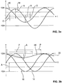
- Fig. 3a shows the time course of the sine track 14 and the cosine track 16, as they are present after the recording step 30.
- the sine track 14 has a negative offset O and an amplitude A that is greater than 1024 bits.
- the amplitude A of the cosine track 16 is less than 1024 bits and its offset O is positive.
- Fig. 3b are the after the adjustment steps 32, 34 amplitude and offset rectified rectified sine and cosine tracks 14, 16 shown their respective offset O a value of zero (0) and whose amplitude corresponds to 1,024 bit.
- the determination of the two parameters A, O of each track 14, 16 takes place either by integrating over a period, a minimum / maximum comparison or applying the Goertzel algorithm to the respective track 14, 16.
- the vibration 44 is recognizable with the amplitude A.
- the phase P of the oscillation 44 with respect to the sine track 14 is approximately 260 ° and the phase P of the oscillation 44 with respect to the cosine track 16 is approximately 350 °. Consequently, in the offset correction step 56, the offset O of the sine track 14 is lowered and the offset O of the cosine track 16 is first increased.
- Fig. 3c the course of the calibrated sine and cosine track 14a, 16a is shown in which within the angular velocity 22 no vibration 44 is more recognizable.
- the corrected sine track 14a has a slightly negative offset O and the corrected cosine track 16a has a positive offset O, these offsets O being stored next to the respective amplitudes A as correction factor 20 in the depositing step 50 in the encoder evaluation 18.
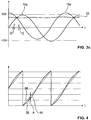
- Fig. 4 an alternative temporal angular course 38 is shown with the vibration 44.
- a temporal angular course of the respective angle 38 itself is used, so that between the individual lines of the incremental encoder 8 a sawtooth-shaped extending optimum angle 58 would result.
- the calculated angle 38 varies by the amplitude A of the vibration 44.
- the invention is not limited to the embodiment described above. Rather, other variants of the invention can be derived therefrom by the person skilled in the art without departing from the subject matter of the invention defined by the claims. In particular, all the individual features described in connection with the exemplary embodiment can also be combined with one another in other ways, without departing from the subject matter of the invention defined by the claims.
Landscapes
- Physics & Mathematics (AREA)
- General Physics & Mathematics (AREA)
- Transmission And Conversion Of Sensor Element Output (AREA)
Applications Claiming Priority (1)
| Application Number | Priority Date | Filing Date | Title |
|---|---|---|---|
| PCT/EP2012/004713 WO2014075698A1 (de) | 2012-11-14 | 2012-11-14 | Verfahren zum kalibrieren eines drehgebers |
Publications (2)
| Publication Number | Publication Date |
|---|---|
| EP2920554A1 EP2920554A1 (de) | 2015-09-23 |
| EP2920554B1 true EP2920554B1 (de) | 2018-11-07 |
Family
ID=47355994
Family Applications (1)
| Application Number | Title | Priority Date | Filing Date |
|---|---|---|---|
| EP12799509.0A Active EP2920554B1 (de) | 2012-11-14 | 2012-11-14 | Verfahren zum kalibrieren eines drehgebers |
Country Status (6)
| Country | Link |
|---|---|
| US (1) | US9329062B2 (es) |
| EP (1) | EP2920554B1 (es) |
| CN (1) | CN104838236B (es) |
| CA (1) | CA2891479C (es) |
| ES (1) | ES2700948T3 (es) |
| WO (1) | WO2014075698A1 (es) |
Cited By (1)
| Publication number | Priority date | Publication date | Assignee | Title |
|---|---|---|---|---|
| DE102023117113A1 (de) | 2023-06-29 | 2025-01-02 | Valeo Detection Systems GmbH | Verfahren und setup zum bestimmen von kalibrierungsdaten und optische strahllenkungsvorrichtung |
Families Citing this family (20)
| Publication number | Priority date | Publication date | Assignee | Title |
|---|---|---|---|---|
| FR3036790B1 (fr) * | 2015-05-27 | 2017-06-02 | Continental Automotive France | Procede de determination de la position d'une piece mobile le long d'un axe a l'aide d'un capteur inductif |
| DE102016101965A1 (de) * | 2016-02-04 | 2017-08-10 | Fraba B.V. | Verfahren zum Kalibrieren eines Drehgebers und Drehgeber zur Bestimmung einer korrigierten Winkelposition |
| CN105842473B (zh) * | 2016-03-30 | 2019-02-01 | 深圳华云数码有限公司 | 一种旋转编码器测速方法及其系统 |
| KR101773334B1 (ko) * | 2016-04-25 | 2017-09-12 | 엘에스산전 주식회사 | 정현파 신호의 단선 검출장치 |
| EP3239664B1 (en) * | 2016-04-26 | 2018-09-26 | ams AG | Signal processing arrangement and signal processing method |
| FR3051039A1 (fr) * | 2016-05-03 | 2017-11-10 | Renault Sas | Procede de correction d'une mesure d'angle d'un rotor dans une machine electrique. |
| CN106248125B (zh) * | 2016-08-30 | 2019-02-05 | 浙江西子富沃德电机有限公司 | 一种带信号质量自检测功能的正余弦光电编码器 |
| KR101834526B1 (ko) * | 2016-09-27 | 2018-04-19 | 성균관대학교산학협력단 | 마그네틱 엔코더의 출력 신호를 보상하는 장치 |
| FR3070759B1 (fr) * | 2017-09-07 | 2020-09-11 | Continental Automotive France | Procede de definition d'une plage de mesure d'un capteur de position inductif |
| JP7107806B2 (ja) * | 2018-09-28 | 2022-07-27 | 株式会社トプコン | ロータリエンコーダ |
| CN109443296A (zh) * | 2018-11-05 | 2019-03-08 | 郑州煤机液压电控有限公司 | 基于角度积分的采煤工作面起伏曲线测量方法 |
| TWI678893B (zh) * | 2018-12-28 | 2019-12-01 | 新代科技股份有限公司 | 一種旋轉編碼器偏心校正裝置 |
| JP6854841B2 (ja) * | 2019-04-19 | 2021-04-07 | 三菱電機株式会社 | 角度検出装置 |
| CN110940371B (zh) * | 2019-12-13 | 2020-08-21 | 浙江禾川科技股份有限公司 | 一种旋转磁电编码器的校准方法、装置及设备 |
| TWI730564B (zh) | 2019-12-26 | 2021-06-11 | 財團法人工業技術研究院 | 編碼器及利用該編碼器的訊號處理方法 |
| CN111089610B (zh) * | 2019-12-28 | 2021-11-23 | 浙江禾川科技股份有限公司 | 一种编码器的信号处理方法、装置及相关组件 |
| KR102655067B1 (ko) * | 2021-12-16 | 2024-04-05 | 현대오토에버 주식회사 | 신호 처리장치 |
| CN117150830B (zh) * | 2023-10-31 | 2024-01-02 | 格陆博科技有限公司 | 一种SinCos位置编码器椭圆校正方法 |
| CN117782187B (zh) * | 2024-02-23 | 2024-05-07 | 泉州昆泰芯微电子科技有限公司 | 一种编码器的非线性误差修正方法及编码器 |
| CN117948872B (zh) * | 2024-03-27 | 2024-06-04 | 常州同惠电子股份有限公司 | 一种基于lm法的电感式位置传感器校准方法及校准系统 |
Family Cites Families (10)
| Publication number | Priority date | Publication date | Assignee | Title |
|---|---|---|---|---|
| US6598196B1 (en) * | 2000-02-29 | 2003-07-22 | Agilent Technologies, Inc. | Technique for correcting errors in position encoders |
| DE10163504B4 (de) | 2001-12-21 | 2005-07-07 | Siemens Ag | Verfahren zur iterativen Fehlerkompensation von sin/cos-Lagemesssystemen nach Offset-, Amplituden- und Phasenfehler |
| JP2004340929A (ja) * | 2003-04-21 | 2004-12-02 | Mitsubishi Electric Corp | 光学式ロータリーエンコーダ |
| DE10335862B4 (de) * | 2003-08-06 | 2007-01-04 | Koenig & Bauer Ag | Verfahren zum Kalibrieren eines inkrementalen Winkelgebers an einem rotierenden Bauteil |
| US7145127B2 (en) * | 2004-08-25 | 2006-12-05 | Avago Technologies Ecbu Ip (Singapore) Pte. Ltd. | Optical encoding that utilizes total internal reflection |
| JP4713123B2 (ja) * | 2004-10-13 | 2011-06-29 | 株式会社ミツトヨ | エンコーダ出力信号補正装置 |
| US7557340B2 (en) * | 2007-10-07 | 2009-07-07 | Avago Technologies Ecbu Ip (Singapore) Pte. Ltd. | Shaft-mounted detector for optical encoder having an aperture through the detector for receiving a rotary shaft of a motor |
| US8179127B2 (en) * | 2007-11-06 | 2012-05-15 | GM Global Technology Operations LLC | Method and apparatus to monitor position of a rotatable shaft |
| EP2058628A3 (en) * | 2007-11-06 | 2016-12-21 | GM Global Technology Operations LLC | Method and apparatus to monitor position of a rotatable shaft |
| JP5263024B2 (ja) * | 2009-06-18 | 2013-08-14 | 株式会社日立製作所 | 回転角検出装置および回転速度検出装置 |
-
2012
- 2012-11-14 EP EP12799509.0A patent/EP2920554B1/de active Active
- 2012-11-14 WO PCT/EP2012/004713 patent/WO2014075698A1/de not_active Ceased
- 2012-11-14 ES ES12799509T patent/ES2700948T3/es active Active
- 2012-11-14 CN CN201280077084.8A patent/CN104838236B/zh active Active
- 2012-11-14 CA CA2891479A patent/CA2891479C/en active Active
-
2015
- 2015-05-14 US US14/712,114 patent/US9329062B2/en active Active
Non-Patent Citations (1)
| Title |
|---|
| None * |
Cited By (1)
| Publication number | Priority date | Publication date | Assignee | Title |
|---|---|---|---|---|
| DE102023117113A1 (de) | 2023-06-29 | 2025-01-02 | Valeo Detection Systems GmbH | Verfahren und setup zum bestimmen von kalibrierungsdaten und optische strahllenkungsvorrichtung |
Also Published As
| Publication number | Publication date |
|---|---|
| CA2891479A1 (en) | 2014-05-22 |
| WO2014075698A1 (de) | 2014-05-22 |
| CN104838236B (zh) | 2017-06-09 |
| US20150247746A1 (en) | 2015-09-03 |
| ES2700948T3 (es) | 2019-02-20 |
| CA2891479C (en) | 2017-10-10 |
| EP2920554A1 (de) | 2015-09-23 |
| US9329062B2 (en) | 2016-05-03 |
| CN104838236A (zh) | 2015-08-12 |
Similar Documents
| Publication | Publication Date | Title |
|---|---|---|
| EP2920554A1 (de) | Verfahren zum kalibrieren eines drehgebers | |
| EP2332249B1 (de) | Bestimmung des rotorwinkels einer synchronmaschine im stillstand mit hilfe von iterativen testpulsen | |
| EP1630363B1 (de) | Verfahren zum Bestimmen der Phasenlage einer Nockenwelle einer Brennkraftmaschine | |
| EP3080555B1 (de) | Vorrichtung und verfahren zur messung eines rotorparameters | |
| EP3134964B1 (de) | Verfahren und anordnung zur verringerung der drehmomentwelligkeit eines gleichstrommotors | |
| DE10149525A1 (de) | Verfahren zur Kompensation mechanischer Schwingungen in Maschinen | |
| DE102014224961A1 (de) | Vorrichtung und Algorythmik zur radialen mechanisch absoluten Winkelbestimmung einer Welle | |
| EP2732243B1 (de) | Verfahren zum überprüfen der plausibilität der ausgangssignale eines resolvers | |
| DE3111113A1 (de) | "regelvorrichtung fuer den motor einer das gewirk beeinflussenden drehvorrichtung, wie teilkettbaum, bei einer kettenwirkmaschine" | |
| WO2013092398A2 (de) | Verfahren und vorrichtung zum korrigieren eines messwertes eines drehwinkels eines rotors einer elektrischen maschine | |
| EP2686952B1 (de) | Verfahren und vorrichtung zur adaption einer kommutierung für eine elektronisch kommutierte elektrische maschine | |
| DE102013224243A1 (de) | Verfahren und Vorrichtung zum Bestimmen einer Stellungsangabe eines Läufers einer elektrischen Maschine | |
| EP3464862B1 (de) | Verfahren und vorrichtung zur kalibrierung eines stellgebersystems | |
| EP2568596B1 (de) | Verfahren und Verarbeitungseinheit zur Bestimmung der Position des Läufers einer Synchronmaschine in Bezug auf den Stator der Synchronmaschine | |
| EP2555417B1 (de) | Bestimmung eines Rotorwinkels eines Elektromotors in einem Fahrzeug mit Radsensoren | |
| EP2295939B1 (de) | Verfahren zur Ermittelung des Feinpositionswertes eines zu überwachenden Körpers | |
| EP3724476B1 (de) | Verfahren und vorrichtung zur bestimmung einer drehwinkelposition einer kurbelwelle einer brennkraftmaschine | |
| DE102016214497A1 (de) | Steuerungseinheit und Verfahren zum Steuern einer elektrischen Maschine | |
| EP3825787B1 (de) | Verfahren zur schnellen regelung des mittelwerts einer regelgrösse, datenträger mit programm sowie motorregelung zur ausführung des verfahrens und antriebsmotor mit einer derartigen motorregelung | |
| EP1334546B1 (de) | Vorrichtung und verfahren zur ermittlung des elektrischen startrotorwinkels | |
| EP3891882B1 (de) | Vorrichtung, anordnung und verfahren zur bestimmung eines winkels zwischen einem rotor und einem stator | |
| EP2721375B1 (de) | Verfahren und vorrichtung zur zyklischen digitalen übertragung eines positionswertes eines bewegten objektes mit träger masse | |
| EP3311111B1 (de) | Verfahren und vorrichtung zur bestimmung eines sensorsignals | |
| WO2013092369A1 (de) | Vorrichtung und verfahren zum bestimmen einer position eines elements | |
| DE102014202247A1 (de) | Korrektur der Ankerposition einer Gleichstrommaschine |
Legal Events
| Date | Code | Title | Description |
|---|---|---|---|
| PUAI | Public reference made under article 153(3) epc to a published international application that has entered the european phase |
Free format text: ORIGINAL CODE: 0009012 |
|
| 17P | Request for examination filed |
Effective date: 20150608 |
|
| AK | Designated contracting states |
Kind code of ref document: A1 Designated state(s): AL AT BE BG CH CY CZ DE DK EE ES FI FR GB GR HR HU IE IS IT LI LT LU LV MC MK MT NL NO PL PT RO RS SE SI SK SM TR |
|
| AX | Request for extension of the european patent |
Extension state: BA ME |
|
| DAX | Request for extension of the european patent (deleted) | ||
| 17Q | First examination report despatched |
Effective date: 20180123 |
|
| REG | Reference to a national code |
Ref country code: DE Ref legal event code: R079 Ref document number: 502012013789 Country of ref document: DE Free format text: PREVIOUS MAIN CLASS: G01D0005244000 Ipc: G01D0005347000 |
|
| GRAP | Despatch of communication of intention to grant a patent |
Free format text: ORIGINAL CODE: EPIDOSNIGR1 |
|
| RIC1 | Information provided on ipc code assigned before grant |
Ipc: G01D 18/00 20060101ALI20180530BHEP Ipc: G01D 5/244 20060101ALI20180530BHEP Ipc: G01P 21/02 20060101ALI20180530BHEP Ipc: G01D 5/347 20060101AFI20180530BHEP |
|
| INTG | Intention to grant announced |
Effective date: 20180626 |
|
| GRAS | Grant fee paid |
Free format text: ORIGINAL CODE: EPIDOSNIGR3 |
|
| GRAA | (expected) grant |
Free format text: ORIGINAL CODE: 0009210 |
|
| AK | Designated contracting states |
Kind code of ref document: B1 Designated state(s): AL AT BE BG CH CY CZ DE DK EE ES FI FR GB GR HR HU IE IS IT LI LT LU LV MC MK MT NL NO PL PT RO RS SE SI SK SM TR |
|
| REG | Reference to a national code |
Ref country code: GB Ref legal event code: FG4D Free format text: NOT ENGLISH |
|
| REG | Reference to a national code |
Ref country code: CH Ref legal event code: EP Ref country code: AT Ref legal event code: REF Ref document number: 1062601 Country of ref document: AT Kind code of ref document: T Effective date: 20181115 |
|
| REG | Reference to a national code |
Ref country code: IE Ref legal event code: FG4D Free format text: LANGUAGE OF EP DOCUMENT: GERMAN |
|
| REG | Reference to a national code |
Ref country code: DE Ref legal event code: R096 Ref document number: 502012013789 Country of ref document: DE |
|
| REG | Reference to a national code |
Ref country code: CH Ref legal event code: NV Representative=s name: E. BLUM AND CO. AG PATENT- UND MARKENANWAELTE , CH |
|
| REG | Reference to a national code |
Ref country code: ES Ref legal event code: FG2A Ref document number: 2700948 Country of ref document: ES Kind code of ref document: T3 Effective date: 20190220 |
|
| REG | Reference to a national code |
Ref country code: NL Ref legal event code: MP Effective date: 20181107 |
|
| REG | Reference to a national code |
Ref country code: LT Ref legal event code: MG4D |
|
| PG25 | Lapsed in a contracting state [announced via postgrant information from national office to epo] |
Ref country code: HR Free format text: LAPSE BECAUSE OF FAILURE TO SUBMIT A TRANSLATION OF THE DESCRIPTION OR TO PAY THE FEE WITHIN THE PRESCRIBED TIME-LIMIT Effective date: 20181107 Ref country code: LT Free format text: LAPSE BECAUSE OF FAILURE TO SUBMIT A TRANSLATION OF THE DESCRIPTION OR TO PAY THE FEE WITHIN THE PRESCRIBED TIME-LIMIT Effective date: 20181107 Ref country code: BG Free format text: LAPSE BECAUSE OF FAILURE TO SUBMIT A TRANSLATION OF THE DESCRIPTION OR TO PAY THE FEE WITHIN THE PRESCRIBED TIME-LIMIT Effective date: 20190207 Ref country code: IS Free format text: LAPSE BECAUSE OF FAILURE TO SUBMIT A TRANSLATION OF THE DESCRIPTION OR TO PAY THE FEE WITHIN THE PRESCRIBED TIME-LIMIT Effective date: 20190307 Ref country code: NO Free format text: LAPSE BECAUSE OF FAILURE TO SUBMIT A TRANSLATION OF THE DESCRIPTION OR TO PAY THE FEE WITHIN THE PRESCRIBED TIME-LIMIT Effective date: 20190207 Ref country code: FI Free format text: LAPSE BECAUSE OF FAILURE TO SUBMIT A TRANSLATION OF THE DESCRIPTION OR TO PAY THE FEE WITHIN THE PRESCRIBED TIME-LIMIT Effective date: 20181107 Ref country code: LV Free format text: LAPSE BECAUSE OF FAILURE TO SUBMIT A TRANSLATION OF THE DESCRIPTION OR TO PAY THE FEE WITHIN THE PRESCRIBED TIME-LIMIT Effective date: 20181107 |
|
| PG25 | Lapsed in a contracting state [announced via postgrant information from national office to epo] |
Ref country code: SE Free format text: LAPSE BECAUSE OF FAILURE TO SUBMIT A TRANSLATION OF THE DESCRIPTION OR TO PAY THE FEE WITHIN THE PRESCRIBED TIME-LIMIT Effective date: 20181107 Ref country code: AL Free format text: LAPSE BECAUSE OF FAILURE TO SUBMIT A TRANSLATION OF THE DESCRIPTION OR TO PAY THE FEE WITHIN THE PRESCRIBED TIME-LIMIT Effective date: 20181107 Ref country code: RS Free format text: LAPSE BECAUSE OF FAILURE TO SUBMIT A TRANSLATION OF THE DESCRIPTION OR TO PAY THE FEE WITHIN THE PRESCRIBED TIME-LIMIT Effective date: 20181107 Ref country code: PT Free format text: LAPSE BECAUSE OF FAILURE TO SUBMIT A TRANSLATION OF THE DESCRIPTION OR TO PAY THE FEE WITHIN THE PRESCRIBED TIME-LIMIT Effective date: 20190307 Ref country code: NL Free format text: LAPSE BECAUSE OF FAILURE TO SUBMIT A TRANSLATION OF THE DESCRIPTION OR TO PAY THE FEE WITHIN THE PRESCRIBED TIME-LIMIT Effective date: 20181107 Ref country code: GR Free format text: LAPSE BECAUSE OF FAILURE TO SUBMIT A TRANSLATION OF THE DESCRIPTION OR TO PAY THE FEE WITHIN THE PRESCRIBED TIME-LIMIT Effective date: 20190208 |
|
| PG25 | Lapsed in a contracting state [announced via postgrant information from national office to epo] |
Ref country code: PL Free format text: LAPSE BECAUSE OF FAILURE TO SUBMIT A TRANSLATION OF THE DESCRIPTION OR TO PAY THE FEE WITHIN THE PRESCRIBED TIME-LIMIT Effective date: 20181107 Ref country code: DK Free format text: LAPSE BECAUSE OF FAILURE TO SUBMIT A TRANSLATION OF THE DESCRIPTION OR TO PAY THE FEE WITHIN THE PRESCRIBED TIME-LIMIT Effective date: 20181107 Ref country code: LU Free format text: LAPSE BECAUSE OF NON-PAYMENT OF DUE FEES Effective date: 20181114 Ref country code: CZ Free format text: LAPSE BECAUSE OF FAILURE TO SUBMIT A TRANSLATION OF THE DESCRIPTION OR TO PAY THE FEE WITHIN THE PRESCRIBED TIME-LIMIT Effective date: 20181107 |
|
| REG | Reference to a national code |
Ref country code: DE Ref legal event code: R097 Ref document number: 502012013789 Country of ref document: DE |
|
| REG | Reference to a national code |
Ref country code: BE Ref legal event code: MM Effective date: 20181130 |
|
| REG | Reference to a national code |
Ref country code: IE Ref legal event code: MM4A |
|
| PG25 | Lapsed in a contracting state [announced via postgrant information from national office to epo] |
Ref country code: RO Free format text: LAPSE BECAUSE OF FAILURE TO SUBMIT A TRANSLATION OF THE DESCRIPTION OR TO PAY THE FEE WITHIN THE PRESCRIBED TIME-LIMIT Effective date: 20181107 Ref country code: SM Free format text: LAPSE BECAUSE OF FAILURE TO SUBMIT A TRANSLATION OF THE DESCRIPTION OR TO PAY THE FEE WITHIN THE PRESCRIBED TIME-LIMIT Effective date: 20181107 Ref country code: EE Free format text: LAPSE BECAUSE OF FAILURE TO SUBMIT A TRANSLATION OF THE DESCRIPTION OR TO PAY THE FEE WITHIN THE PRESCRIBED TIME-LIMIT Effective date: 20181107 Ref country code: MC Free format text: LAPSE BECAUSE OF FAILURE TO SUBMIT A TRANSLATION OF THE DESCRIPTION OR TO PAY THE FEE WITHIN THE PRESCRIBED TIME-LIMIT Effective date: 20181107 Ref country code: SK Free format text: LAPSE BECAUSE OF FAILURE TO SUBMIT A TRANSLATION OF THE DESCRIPTION OR TO PAY THE FEE WITHIN THE PRESCRIBED TIME-LIMIT Effective date: 20181107 |
|
| PLBE | No opposition filed within time limit |
Free format text: ORIGINAL CODE: 0009261 |
|
| STAA | Information on the status of an ep patent application or granted ep patent |
Free format text: STATUS: NO OPPOSITION FILED WITHIN TIME LIMIT |
|
| 26N | No opposition filed |
Effective date: 20190808 |
|
| GBPC | Gb: european patent ceased through non-payment of renewal fee |
Effective date: 20190207 |
|
| PG25 | Lapsed in a contracting state [announced via postgrant information from national office to epo] |
Ref country code: SI Free format text: LAPSE BECAUSE OF FAILURE TO SUBMIT A TRANSLATION OF THE DESCRIPTION OR TO PAY THE FEE WITHIN THE PRESCRIBED TIME-LIMIT Effective date: 20181107 Ref country code: IE Free format text: LAPSE BECAUSE OF NON-PAYMENT OF DUE FEES Effective date: 20181114 |
|
| PG25 | Lapsed in a contracting state [announced via postgrant information from national office to epo] |
Ref country code: BE Free format text: LAPSE BECAUSE OF NON-PAYMENT OF DUE FEES Effective date: 20181130 |
|
| PG25 | Lapsed in a contracting state [announced via postgrant information from national office to epo] |
Ref country code: GB Free format text: LAPSE BECAUSE OF NON-PAYMENT OF DUE FEES Effective date: 20190207 Ref country code: MT Free format text: LAPSE BECAUSE OF FAILURE TO SUBMIT A TRANSLATION OF THE DESCRIPTION OR TO PAY THE FEE WITHIN THE PRESCRIBED TIME-LIMIT Effective date: 20181107 |
|
| PG25 | Lapsed in a contracting state [announced via postgrant information from national office to epo] |
Ref country code: TR Free format text: LAPSE BECAUSE OF FAILURE TO SUBMIT A TRANSLATION OF THE DESCRIPTION OR TO PAY THE FEE WITHIN THE PRESCRIBED TIME-LIMIT Effective date: 20181107 |
|
| PG25 | Lapsed in a contracting state [announced via postgrant information from national office to epo] |
Ref country code: CY Free format text: LAPSE BECAUSE OF FAILURE TO SUBMIT A TRANSLATION OF THE DESCRIPTION OR TO PAY THE FEE WITHIN THE PRESCRIBED TIME-LIMIT Effective date: 20181107 Ref country code: MK Free format text: LAPSE BECAUSE OF NON-PAYMENT OF DUE FEES Effective date: 20181107 Ref country code: HU Free format text: LAPSE BECAUSE OF FAILURE TO SUBMIT A TRANSLATION OF THE DESCRIPTION OR TO PAY THE FEE WITHIN THE PRESCRIBED TIME-LIMIT; INVALID AB INITIO Effective date: 20121114 |
|
| PGFP | Annual fee paid to national office [announced via postgrant information from national office to epo] |
Ref country code: ES Payment date: 20231215 Year of fee payment: 12 |
|
| PGFP | Annual fee paid to national office [announced via postgrant information from national office to epo] |
Ref country code: FR Payment date: 20231122 Year of fee payment: 12 |
|
| PGFP | Annual fee paid to national office [announced via postgrant information from national office to epo] |
Ref country code: IT Payment date: 20241129 Year of fee payment: 13 |
|
| PG25 | Lapsed in a contracting state [announced via postgrant information from national office to epo] |
Ref country code: FR Free format text: LAPSE BECAUSE OF NON-PAYMENT OF DUE FEES Effective date: 20241130 |
|
| REG | Reference to a national code |
Ref country code: CH Ref legal event code: U11 Free format text: ST27 STATUS EVENT CODE: U-0-0-U10-U11 (AS PROVIDED BY THE NATIONAL OFFICE) Effective date: 20251201 |
|
| REG | Reference to a national code |
Ref country code: ES Ref legal event code: FD2A Effective date: 20260105 |
|
| PGFP | Annual fee paid to national office [announced via postgrant information from national office to epo] |
Ref country code: DE Payment date: 20251118 Year of fee payment: 14 |
|
| PGFP | Annual fee paid to national office [announced via postgrant information from national office to epo] |
Ref country code: AT Payment date: 20251117 Year of fee payment: 14 |
|
| PGFP | Annual fee paid to national office [announced via postgrant information from national office to epo] |
Ref country code: CH Payment date: 20251201 Year of fee payment: 14 |
|
| PG25 | Lapsed in a contracting state [announced via postgrant information from national office to epo] |
Ref country code: ES Free format text: LAPSE BECAUSE OF NON-PAYMENT OF DUE FEES Effective date: 20241115 |