EP2920034B1 - Sicherheitsgurteinrichtung in einem fahrzeug - Google Patents
Sicherheitsgurteinrichtung in einem fahrzeug Download PDFInfo
- Publication number
- EP2920034B1 EP2920034B1 EP13791769.6A EP13791769A EP2920034B1 EP 2920034 B1 EP2920034 B1 EP 2920034B1 EP 13791769 A EP13791769 A EP 13791769A EP 2920034 B1 EP2920034 B1 EP 2920034B1
- Authority
- EP
- European Patent Office
- Prior art keywords
- clamping
- belt
- contour
- belt strap
- strap
- Prior art date
- Legal status (The legal status is an assumption and is not a legal conclusion. Google has not performed a legal analysis and makes no representation as to the accuracy of the status listed.)
- Active
Links
Images




Classifications
-
- B—PERFORMING OPERATIONS; TRANSPORTING
- B60—VEHICLES IN GENERAL
- B60R—VEHICLES, VEHICLE FITTINGS, OR VEHICLE PARTS, NOT OTHERWISE PROVIDED FOR
- B60R22/00—Safety belts or body harnesses in vehicles
- B60R22/30—Coupling devices other than buckles, including length-adjusting fittings or anti-slip devices
-
- A—HUMAN NECESSITIES
- A44—HABERDASHERY; JEWELLERY
- A44B—BUTTONS, PINS, BUCKLES, SLIDE FASTENERS, OR THE LIKE
- A44B11/00—Buckles; Similar fasteners for interconnecting straps or the like, e.g. for safety belts
- A44B11/02—Buckles; Similar fasteners for interconnecting straps or the like, e.g. for safety belts frictionally engaging surface of straps
- A44B11/06—Buckles; Similar fasteners for interconnecting straps or the like, e.g. for safety belts frictionally engaging surface of straps with clamping devices
-
- A—HUMAN NECESSITIES
- A44—HABERDASHERY; JEWELLERY
- A44B—BUTTONS, PINS, BUCKLES, SLIDE FASTENERS, OR THE LIKE
- A44B11/00—Buckles; Similar fasteners for interconnecting straps or the like, e.g. for safety belts
- A44B11/25—Buckles; Similar fasteners for interconnecting straps or the like, e.g. for safety belts with two or more separable parts
- A44B11/2503—Safety buckles
- A44B11/2546—Details
- A44B11/2553—Attachment of buckle to strap
- A44B11/2557—Attachment of buckle to strap with strap length adjustment
-
- A—HUMAN NECESSITIES
- A44—HABERDASHERY; JEWELLERY
- A44B—BUTTONS, PINS, BUCKLES, SLIDE FASTENERS, OR THE LIKE
- A44B11/00—Buckles; Similar fasteners for interconnecting straps or the like, e.g. for safety belts
- A44B11/25—Buckles; Similar fasteners for interconnecting straps or the like, e.g. for safety belts with two or more separable parts
- A44B11/2503—Safety buckles
- A44B11/2546—Details
- A44B11/2561—Tongue elements
-
- B—PERFORMING OPERATIONS; TRANSPORTING
- B60—VEHICLES IN GENERAL
- B60R—VEHICLES, VEHICLE FITTINGS, OR VEHICLE PARTS, NOT OTHERWISE PROVIDED FOR
- B60R22/00—Safety belts or body harnesses in vehicles
- B60R22/18—Anchoring devices
- B60R2022/1812—Connections between seat belt and buckle tongue
-
- Y—GENERAL TAGGING OF NEW TECHNOLOGICAL DEVELOPMENTS; GENERAL TAGGING OF CROSS-SECTIONAL TECHNOLOGIES SPANNING OVER SEVERAL SECTIONS OF THE IPC; TECHNICAL SUBJECTS COVERED BY FORMER USPC CROSS-REFERENCE ART COLLECTIONS [XRACs] AND DIGESTS
- Y10—TECHNICAL SUBJECTS COVERED BY FORMER USPC
- Y10T—TECHNICAL SUBJECTS COVERED BY FORMER US CLASSIFICATION
- Y10T24/00—Buckles, buttons, clasps, etc.
- Y10T24/40—Buckles
- Y10T24/4002—Harness
- Y10T24/4012—Clamping
- Y10T24/4016—Pivoted part or lever
Definitions
- the invention relates to a belt fitting for a seat belt device in a vehicle according to the preamble of claim 1.
- the seat belt device of a vehicle may have, for example, a lap belt as well as a shoulder belt extending diagonally over the upper body of the vehicle occupant.
- the lap belt is anchored to the vehicle body via two laterally opposite, lower attachment points when the seat belt is worn.
- a provided on the lap belt Gurtbeschlag whose tongue is plugged into a body side anchored seat belt buckle.
- a Gurtbeschlag with a base portion and an adjoining tongue is known.
- a Gurtinate is provided, through which a webbing is guided.
- the strap eyelet splits the webbing into a lap belt portion and a shoulder belt portion.
- a clamping element is provided which is adjustable between a release position in which the webbing is freely movable through the Gurtsammlung, and a clamping position in which the webbing between the clamping element and an abutment acting clamping stop is clamped with a clamping force.
- the clamping element is pivotable about an axis of rotation between the release position and the clamping position and elastically biased in the direction of the release position.
- the webbing In normal driving, the webbing is thus freely movable over a running surface of the clamping element.
- act in the event of a crash on the clamping element increased belt forces. This results in that the clamping element is displaced in a rotational direction into the clamping position in which the webbing is clamped with the clamping force between the clamping element and the clamping stop.
- the clamping element has a clamping web extending in the webbing transverse direction.
- the clamping bar is in the clamping position in line contact with the webbing, and indeed throughout between the two webbing outer edges in the webbing transverse direction. In this way results over the webbing transverse direction away between the two webbing outer edges a linear, uniform or constant clamping force distribution.
- a generic strap fitting which has a clamping element with a sawtooth-like clamping contour.
- a Gurtbeschlag for a seat belt device in a vehicle which has a Gurtexcellent whose edge contour is formed partially sinusoidal.
- DE 27 41 297 is considered to be the closest prior art and discloses a Gurtbeschlag with the features of the preamble of claim 1.
- the object of the invention is to provide a belt fitting for a seat belt in a vehicle, which increases the reliability of the seat belt device in the event of a crash.
- the invention is based on the fact that the belt forces occurring in the context of dynamic safety tests lead to an overload of the clamped webbing tissue. This is due, inter alia, to the linear, uniform clamping force distribution in the webbing transverse direction exerted by the clamping web. Against this background, the clamping element and / or acting as an abutment clamping stop on a clamping contour with which the webbing is not applied in the clamping position in uniform or in the transverse direction linear, rectilinear clamping force distribution, but rather on the Gurtbandbreite in a non-linear and / or uneven clamping force distribution is clamped.
- a particularly preferred embodiment is based on the finding that a Gurtbandriss is often initiated at the outer edges of the webbing. Against this background, it is particularly preferred if the clamping force distribution - in comparison to the belt center - is reduced especially at the outer edges of the belt webbing or none Clamping force introduction in the area of the outer edges takes place. Accordingly, the clamping contour of the clamping element and / or the clamping stop in the webbing transverse direction can be spaced by a transverse offset from the webbing outer edges.
- the clamping contour may have at least one clamping projection which protrudes from a base surface of the clamping element and / or the clamping impact by a height which is in particular less than or equal to the webbing material thickness.
- the clamping projection is a crowning or a bulge whose apex in the clamping position presses approximately centrally on the strap.
- the vertex may each have laterally sloping arc sections in the webbing transverse direction, which pass into the above-mentioned base area of the clamping element / clamping stop.
- the clamping element in the base portion of the belt fitting can be pivotable about an axis of rotation between the release position and the clamping position.
- the clamping element can also be resiliently biased by a spring element in the release position.
- the webbing can be performed with a seat belt in sliding contact and freely movable over a running surface of the clamping element.
- the clamping element remains elastically biased in its release position.
- significantly greater belt forces act on the belt fitting and thus also on the clamping element. By applying this increased belt forces, the clamping element can be displaced in a direction of rotation into the clamping position. In this way, the lap belt portion of the seat belt is safely blocked.
- the clamping elements pivotable about the axis of rotation may have at least one contour section leading in the above-mentioned rotational direction, which is arranged around a longitudinal offset in front of at least one contour section trailing in the direction of rotation.
- the leading contour section first comes into clamping contact with the web, while the contour section, trailing in the direction of rotation, only comes into clamping contact with the webbing in a time-delayed manner and spaced apart by a longitudinal offset.
- the contour section protruding in the direction of rotation can be arranged centrally in the webbing transverse direction and merge into trailing contour sections arranged at each edge.
- trailing contour section in the direction of rotation be arranged centrally in the webbing transverse direction and merge in each edge arranged leading leading contour sections.
- the above-mentioned peak may not be punctiform and centered in the transverse direction y, but rather extend in the transverse direction over a central region.
- This vertex area can pass on the outside in each case laterally sloping arc sections or outer edges.
- the clamping bar can thus be designed straight linear in the central region, with only its outer edges are rounded or beveled.
- the length of the rectilinear and / or linear central region of the vertex is less than 85%, in particular less than 75% and / or more preferably more than 50% of the belt width.
- the total length of the clamping bar can be particularly preferably in a range of about 51 mm.
- the length of the above mentioned arc sections can be about 10mm per side.
- a shoulder belt portion 1 and a lap belt portion 3 formed three-point seat belt shown.
- the driver's seat and the vehicle occupant is not shown for reasons of clarity.
- the also not shown upper end of the shoulder belt portion 1 is connected to a retractor, not shown, which is arranged for example in the B-pillar.
- a retractor not shown, which is arranged for example in the B-pillar.
- the Fig. 1 extends the lap belt section 3 in the vehicle transverse direction y from an outer connection point, not shown, to a Gurtbeschlag 7, which is inserted with a tongue 9 in a buckle 11.
- the Gurtbeschlag 1 is composed of a base portion 13 and the aforementioned tongue 9 together.
- the base portion 13 of the belt fitting 1 has a strap eye 15, through which the webbing 5 is guided.
- the webbing 5 is divided at the Gurtinate 15 in the Schultergurtabites 1 and in the lap belt section 3.
- a strip-shaped clamping element 17 is pivotally articulated about a rotation axis A.
- the clamping element 17 is in the normal driving operation by means of a spring 19 (FIG. Fig. 2 ) in one, in the Fig. 3 shown release position I elastically biased.
- the webbing 5 is freely movable and guided in sliding contact over a running surface 19 of the clamping element.
- the clamping element 17 is limited in the release position I together with an integrally formed on the base portion 7 Clamping 23 a nip 21 ( Fig. 2 ).
- FIG. 4 the strap fitting is shown in the event of a crash.
- greatly increased belt forces F B , F S act on the lap belt section 3 and the shoulder section 1 of the safety belt.
- the clamping element 17 is subjected to increased belt forces, whereby the clamping element 17 is displaced in a rotational direction R in the clamping position II.
- a molded on the clamping element 17 clamping web 25 presses with a clamping force F K, the webbing 5 against the clamping collar 23. In this way, the lap belt section 3 is blocked in the event of a crash in safety.
- the clamping web 25 of the clamping element 17 in the webbing transverse direction y is not rectilinear and planar contoured, but the clamping web 25 in the transverse direction y a crowning or bulging, with a centered approximately in the transverse direction y vertex 29 and in the vertex 29 and the side thereof sloping arc portions 31 result according to the Fig. 5 a clamping contour K, which gives the over the belt width b the drawn clamping force distribution F (b).
- the apex 29 of the crown protrudes by a height ⁇ h from a base surface 30 of the clamping web 25, which is less than or equal to the webbing material thickness s, which is usually in a range of 1.2 mm.
- clamping position II results between the two webbing outer edges 33 is not a consistently linear and uniform profile of the clamping force distribution, but rather a non-linear clamping force distribution F (b) with a maximum clamping force F K, max in the middle of the webbing 5. Accordingly, there is specifically at the outer edges 33 of the webbing 5 only a slight or possibly no clamping force application.
- clamping projections 35 merge into one another in a sinusoidal manner, wherein the indicated amplitude height ⁇ h can likewise be smaller than or equal to the webbing material thickness s.
- Fig. 7 has the clamping contour K of the clamping web 25 in the webbing transverse direction y successive contour sections 37, 39.
- the contour sections 37, 39 are viewed in the webbing longitudinal direction x offset by a longitudinal offset .DELTA.x to each other. moreover go the contour sections 37, 39 sinusoidally into each other.
- the ahead in the direction of rotation R contour portion in the webbing transverse direction y is arranged centrally and this is in each case arranged at the edge, leading ahead contour sections 39 on.
- Fig. 9 is in a view corresponding to the Fig. 5 a further embodiment of the invention shown.
- the vertex 29 is not punctiform and arranged centrally in the transverse direction y, but extends the vertex 29 in the transverse direction y over a central region, which merges on the outside in each of the laterally sloping arc sections 31.
- the outer contour of the over the central region rectilinear vertex 29 is formed parallel to the axis of rotation A of the clamping bar 25. Accordingly, in the Fig. 9 the clamping force distribution F (b) not as in the Fig. 5 bell-shaped, but has this in the central region of the webbing a plateau with a substantially constant clamping force curve.
- the clamping web 25 is designed in the middle region straight / linear, with only the outer edges 31 are rounded or beveled.
- the length of the rounded portions 31 in the transverse direction y can be about 10 mm per side.
- the total length of the clamping web 25 may be in a range of about 51mm in each of the illustrated embodiments.
Landscapes
- Engineering & Computer Science (AREA)
- Mechanical Engineering (AREA)
- Automotive Seat Belt Assembly (AREA)
Description
- Die Erfindung betrifft einen Gurtbeschlag für eine Sicherheitsgurteinrichtung in einem Fahrzeug nach dem Oberbegriff des Patentanspruches 1.
- Die Sicherheitsgurteinrichtung eines Fahrzeuges kann beispielhaft einen Beckengurt sowie einen diagonal über den Oberkörper des Fahrzeuginsassen verlaufenden Schultergurt aufweisen. Der Beckengurt ist bei angelegtem Sicherheitsgurt über zwei seitlich gegenüberliegende, untere Anbindungspunkte am Fahrzeugaufbau verankert. Üblicherweise ist in der Fahrzeugquerrichtung innen gelegene Anlegungspunkt lösbar ausgeführt, und zwar mit einem am Beckengurt vorgesehen Gurtbeschlag, dessen Steckzunge in ein aufbauseitig verankertes Gurtschloss einsteckbar ist.
- Aus der
DE 42 15 384 A1 ist ein Gurtbeschlag mit einem Basisabschnitt und einer daran anschließenden Steckzunge bekannt. Im Basisabschnitt ist eine Gurtöse vorgesehen, durch die ein Gurtband geführt ist. Bei angelegtem Sicherheitsgurt teilt die Gurtöse das Gurtband in einen Beckengurtabschnitt und in einen Schultergurtabschnitt auf. Um im Crashfall den Beckengurtabschnitt des Gurtbandes zu blockieren, ist ein Klemmelement vorgesehen, das zwischen einer Freigabestellung, in der das Gurtband frei bewegbar durch die Gurtöse hindurch geführt ist, und einer Klemmstellung verstellbar ist, in der das Gurtband zwischen dem Klemmelement und einem als Widerlager wirkenden Klemmanschlag mit einer Klemmkraft festgeklemmt ist. Das Klemmelement ist um eine Drehachse zwischen der Freigabestellung und der Klemmstellung schwenkbar sowie in Richtung der Freigabestellung elastisch vorgespannt. Im normalen Fahrbetrieb ist somit das Gurtband frei bewegbar über eine Lauffläche des Klemmelementes geführt. Demgegenüber wirken im Crashfall auf das Klemmelement erhöhte Gurtkräfte. Dies führt dazu, dass das Klemmelement in einer Drehrichtung bis in die Klemmstellung verlagert wird, in der das Gurtband mit der Klemmkraft zwischen dem Klemmelement und dem Klemmanschlag festgeklemmt ist. - Im Stand der Technik weist das Klemmelement einen Klemmsteg auf, der in der Gurtband-Querrichtung verläuft. Der Klemmsteg ist in der Klemmstellung in einem Linienkontakt mit dem Gurtband, und zwar durchgängig zwischen den beiden Gurtband-Außenkanten in der Gurtband-Querrichtung. Auf diese Weise ergibt sich über die Gurtband-Querrichtung hinweg zwischen den beiden Gurtband-Außenkanten eine lineare, gleichmäßige bzw. konstante Klemmkraftverteilung.
- In dynamischen Sicherheitsversuchen wurde festgestellt, dass das im Crashfall zwischen dem Klemmelement und dem Klemmanschlag festgeklemmte Gurtband-Gewebe einer übermäßig hohen Belastung ausgesetzt sein kann, wodurch die Gefahr von Gurtbandrissen besteht.
- Aus der
US 4 979 764 A ist ein gattungsgemäßer Gurtbeschlag bekannt, der ein Klemmelement mit einer sägezahnartigen Klemmkontur aufweist. Aus derDE 27 41 297 ist ein Gurtbeschlag für eine Sicherheitsgurteinrichtung in einem Fahrzeug bekannt, der eine Gurtöse aufweist, deren Randkontur teilweise sinusförmig ausgebildet ist.DE 27 41 297 wird als nächstliegender Stand der Technik angesehen und offenbart ein Gurtbeschlag mit den Merkmalen des Oberbegriffs des Anspruchs 1. Die Aufgabe der Erfindung besteht darin, einen Gurtbeschlag für eine Sicherheitsgurteinrichtung in einem Fahrzeug bereitzustellen, der im Crashfall die Betriebssicherheit der Sicherheitsgurteinrichtung erhöht. - Die Aufgabe ist durch die Merkmale des Patentanspruches 1 gelöst. Bevorzugte Weiterbildungen der Erfindung sind in den abhängigen Ansprüchen offenbart.
- Die Erfindung beruht auf dem Sachverhalt, dass die im Rahmen dynamischer Sicherheitsversuche auftretenden Gurtkräfte zu einer Überlastung des festgeklemmten Gurtband-Gewebes führen. Dies ist unter anderem auf die vom Klemmsteg ausgeübte lineare, gleichmäßige Klemmkraftverteilung in der Gurtband-Querrichtung zurückzuführen. Vor diesem Hintergrund weist das Klemmelement und/oder der als Widerlager wirkenden Klemmanschlag eine Klemmkontur auf, mit der das Gurtband in der Klemmstellung nicht in gleichmäßiger oder in der Querrichtung linearer, geradliniger Klemmkraftverteilung beaufschlagt ist, sondern vielmehr über die Gurtbandbreite in einer nicht linearen und/oder ungleichmäßigen Klemmkraftverteilung festgeklemmt wird. Auf diese Weise wird das Gurtband-Gewebe im Klemmbereich in der Gurtband-Querrichtung partiell entlastet, wodurch die Gefahr von Gurtbandrissen reduziert ist. Im Crashfall ergibt sich durch diese spezielle Klemmkontur ein in der Gurtband-Querrichtung ungleichmäßiger sowie nicht linearer Verlauf der Kräfteverteilung.
- Eine besonders bevorzugte Ausführungsvariante beruht auf der Erkenntnis, dass ein Gurtbandriss häufig an den Außenkanten des Gurtbandes eingeleitet wird. Vor diesem Hintergrund ist es besonders bevorzugt, wenn die Klemmkraftverteilung - im Vergleich zur Gurtband-Mitte - speziell an den Gurtband-Außenkanten reduziert ist oder keine Klemmkraft-Einleitung im Bereich der Außenkanten erfolgt. Entsprechend kann die Klemmkontur des Klemmelementes und/oder des Klemmanschlags in der Gurtband-Querrichtung um einen Querversatz von dem Gurtband-Außenkanten beabstandet sein.
- In einer weiteren Ausführungsform kann die Klemmkontur zumindest einen Klemmvorsprung aufweisen, der von einer Grundfläche des Klemmelementes und/oder des Klemmanschlages um eine Höhe vorragt, die insbesondere kleiner oder gleich der Gurtband-Materialstärke ist. Erfindungsgemäß ist der Klemmvorsprung eine Bombierung beziehungsweise eine Ausbauchung, deren Scheitel in der Klemmstellung in etwa mittig auf das Gurtband drückt. Der Scheitel kann in der Gurtband-Querrichtung jeweils seitlich abfallende Bogenabschnitte aufweisen, die in die oben erwähnte Grundfläche des Klemmelementes/Klemmanschlags übergehen.
- Zur Realisierung eines erfindungsgemäßen Gurtbeschlages kann das Klemmelement im Basisabschnitt des Gurtbeschlages um eine Drehachse zwischen der Freigabestellung und der Klemmstellung schwenkbar sein. Das Klemmelement kann zudem mittels eines Federelementes in die Freigabestellung elastisch vorgespannt sein. Im normalen Fahrbetrieb kann das Gurtband bei angelegtem Sicherheitsgurt in Gleitkontakt sowie frei bewegbar über eine Lauffläche des Klemmelementes geführt werden. In diesem Fall verbleibt das Klemmelement elastisch vorgespannt in seiner Freigabestellung. Demgegenüber wirken im Crashfall wesentlich größere Gurtkräfte auf den Gurtbeschlag und damit auch auf das Klemmelement ein. Unter Beaufschlagung dieser erhöhten Gurtkräfte kann das Klemmelement in einer Drehrichtung bis in die Klemmstellung verlagert werden. Auf diese Weise wird der Beckengurtabschnitt des Sicherheitsgurtes sicherheitsgünstig blockiert.
- Das um die Drehachse schwenkbare Klemmelemente kann zumindest einen, in der oben erwähnten Drehrichtung vorauseilenden Konturabschnitt aufweisen, der um einen Längsversatz vor zumindest einem, in der Drehrichtung nacheilenden Konturabschnitt angeordnet ist. Im Crashfall kommt somit zuerst der vorauseilende Konturabschnitt in Klemmkontakt mit dem Gurtsteg, während der in der Drehrichtung nacheilende Konturabschnitt erst zeitverzögert sowie um einen Längsversatz beabstandet mit dem Gurtband in Klemmkontakt kommt.
- In einer Ausführungsvariante kann der in der Drehrichtung vorauseilende Konturabschnitt in der Gurtband-Querrichtung mittig angeordnet sein und in jeweils randseitig angeordnete, nacheilende Konturabschnitte übergehen. Alternativ dazu kann der in der Drehrichtung nacheilende Konturabschnitt in der Gurtband-Querrichtung mittig angeordnet sein und in jeweils randseitig angeordnete vorauseilende Konturabschnitte übergehen.
- In einer besonderen Ausführungsform kann der oben erwähnte Scheitel nicht punktförmig sowie mittig in der Querrichtung y angeordnet sein, sondern sich vielmehr in der Querrichtung über einen Mittelbereich hinweg erstrecken. Dieser Scheitelbereich kann außenseitig jeweils in seitlich abfallenden Bogenabschnitte bzw. Außenkanten übergehen. Entsprechend weist der Klemmkraftverlauf im Mittelbereich des Gurtbandes ein Plateau mit im Wesentlich konstantem Klemmkraftverlauf auf. Der Klemmsteg kann also im Mittelbereich geradellinear ausgeführt, wobei nur dessen Außenkanten abgerundet bzw. gefast sind. Bevorzugt beträgt die Länge des geradlinig und/oder linear verlaufenden Mittelbereichs des Scheitels weniger als 85%, insbesondere weniger als 75% und/oder weiter bevorzugt mehr als 50% der Gurtbandbreite.
- Die Gesamtlänge des Klemmsteges kann besonders bevorzugt in einem Bereich von etwa 51 mm liegen. Die Länge der oben erwähnten Bogenabschnitte kann je Seite bei ca. 10mm liegen.
- Die vorstehend erläuterten und/oder in den Unteransprüchen wiedergegebenen vorteilhaften Aus- und/oder Weiterbildungen der Erfindung können - außer zum Beispiel in den Fällen eindeutiger Abhängigkeiten oder unvereinbarer Alternativen - einzeln oder aber auch in beliebiger Kombination miteinander zur Anwendung kommen.
- Die Erfindung und ihre vorteilhaften Aus- und Weiterbildungen sowie deren Vorteile werden nachfolgend anhand von Zeichnungen näher erläutert.
-
- Fig. 1
- einen Ausschnitt einer Dreipunkt-Sicherheitsgurteinrichtung in einer Gebrauchslage, bei der der Sicherheitsgurt am Fahrzeuginsassen angelegt ist;
- Fig. 2
- den Gurtbeschlag in einer Explosionsdarstellung;
- Fig. 3
- eine vergrößerte Schnittansicht entlang der Schnittebene I-I aus der
Fig. 1 , in der das Klemmelement in der Freigabestellung gezeigt ist; - Fig. 4
- in einer Ansicht entsprechend der
Fig. 3 das Klemmelement in der Klemmstellung; - Fig. 5
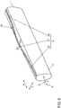
- in einer stark vergrößerten sowie vereinfachten Prinzipdarstellung ein Klemmelement in seiner Klemmstellung sowie ein Diagramm zur Klemmkraftverteilung;
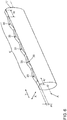
- Fig. 6 bis 8
- jeweils Perspektivdarstellungen von Klemmelementen mit unterschiedlichen Klemmkonturen, wobei die
Fig. 6 nicht von der Erfindung umfasst ist; und - Fig. 9
- in einer Ansicht entsprechend der
Fig. 5 eine weitere Ausführungsvariante des Klemmelements. - In der Teilansicht der
Fig. 1 ist in einer Gebrauchslage, d.h. bei am Fahrzeuginsassen angelegtem Sicherheitsgurt, ein aus einem Schultergurtabschnitt 1 und einem Beckengurtabschnitt 3 gebildeter Dreipunkt-Sicherheitsgurt gezeigt. Der Fahrersitz sowie der Fahrzeuginsasse ist aus Gründen der Übersichtlichkeit nicht dargestellt. Das ebenfalls nicht gezeigte obere Ende des Schultergurtabschnittes 1 ist mit einem nicht dargestellten Retraktor verbunden, der zum Beispiel in der B-Säule angeordnet ist. Gemäß derFig. 1 erstreckt sich der Beckengurtabschnitt 3 in der Fahrzeugquerrichtung y von einem nicht gezeigten äußeren Anbindungspunkt bis zu einem Gurtbeschlag 7, der mit einer Steckzunge 9 in ein Gurtschloss 11 eingesteckt ist. - Der Gurtbeschlag 1 setzt sich aus einem Basisabschnitt 13 sowie der bereits erwähnten Steckzunge 9 zusammen. Der Basisabschnitt 13 des Gurtbeschlages 1 weist eine Gurtöse 15 auf, durch die das Gurtband 5 geführt ist. Bei dem in der
Fig. 1 dargestellten angelegten Sicherheitsgurt ist das Gurtband 5 an der Gurtöse 15 in den Schultergurtabschnitt 1 und in den Beckengurtabschnitt 3 aufgeteilt. - Wie aus den
Fig. 2 und3 hervorgeht, ist am Basisabschnitt 13 des Gurtbeschlages 7 ein leistenförmiges Klemmelement 17 um eine Drehachse A schwenkbar angelenkt. Das Klemmelement 17 ist im normalen Fahrbetrieb mittels einer Feder 19 (Fig. 2 ) in eine, in derFig. 3 gezeigte Freigabestellung I elastisch vorgespannt. In der Freigabestellung I ist das Gurtband 5 frei bewegbar sowie in Gleitkontakt über eine Lauffläche 19 des Klemmelementes geführt. - Das Klemmelement 17 begrenzt in der Freigabestellung I zusammen mit einem am Basisabschnitt 7 angeformten Klemmansatz 23 einen Klemmspalt 21 (
Fig. 2 ). - In der
Fig. 4 ist der Gurtbeschlag im Crashfall dargestellt. Im Crashfall wirken stark erhöhte Gurtkräfte FB, FS auf den Beckengurtabschnitt 3 und dem Schulterabschnitt 1 des Sicherheitsgurtes. Dadurch wird auch das Klemmelement 17 mit erhöhten Gurtkräften beaufschlagt, wodurch das Klemmelement 17 in einer Drehrichtung R in die Klemmstellung II verlagert wird. In der Klemmstellung II drückt ein am Klemmelement 17 angeformter Klemmsteg 25 mit einer Klemmkraft FK das Gurtband 5 gegen den Klemmansatz 23. Auf diese Weise wird im Crashfall der Beckengurtabschnitt 3 sicherheitsgünstig blockiert. - Gemäß der
Fig. 5 ist der Klemmsteg 25 des Klemmelementes 17 in der Gurtband-Querrichtung y nicht geradlinig sowie plan konturiert, sondern weist der Klemmsteg 25 in der Querrichtung y eine Bombierung beziehungsweise Ausbauchung auf, und zwar mit einem in etwa in der Querrichtung y mittig angeordneten Scheitel 29 sowie in der Querrichtung y seitlich abfallenden Bogenabschnitten 31. Der Scheitel 29 sowie die seitlich davon abfallenden Bogenabschnitte 31 ergeben gemäß derFig. 5 eine Klemmkontur K, die die über die Gurtbandbreite b die eingezeichnete Klemmkraftverteilung F(b) ergibt. Der Scheitel 29 der Bombierung ragt um eine Höhe Δh von einer Grundfläche 30 des Klemmsteges 25 vor, der kleiner oder gleich der Gurtband-Materialstärke s ist, die üblicherweise in einem Bereich von 1,2 mm liegt. - In der, in der
Fig. 5 gezeigten Klemmstellung II ergibt sich zwischen den beiden Gurtband-Außenkanten 33 kein durchgängig linearer sowie gleichmäßiger Verlauf der Klemmkraftverteilung, sondern vielmehr eine nicht lineare Klemmkraftverteilung F(b) mit einer maximalen Klemmkraft FK,max in der Mitte des Gurtbandes 5. Entsprechend ergibt sich speziell an den Außenkanten 33 des Gurtbandes 5 nur eine geringe oder ggf. überhaupt keine Klemmkraft-Beaufschlagung. - In der
Fig. 6 weist der Klemmsteg 25 des Klemmelementes 17 eine in der Gurtband-Querrichtung y wellenförmige Klemmkontur K, bestehend aus insgesamt 6 Klemmvorsprüngen 35, auf. DieFig. 6 ist nicht von der Erfindung umfasst. - Die Klemmvorsprünge 35 gehen dabei sinusförmig ineinander über, wobei die angedeutete Amplitudenhöhe Δh ebenfalls kleiner oder gleich der Gurtband-Materialstärke s sein kann.
- In der
Fig. 7 weist die Klemmkontur K des Klemmsteges 25 in der Gurtband-Querrichtung y aufeinanderfolgende Konturabschnitte 37, 39 auf. Die Konturabschnitte 37, 39 sind in der Gurtband-Längsrichtung x betrachtet um einen Längsversatz Δx zueinander versetzt. Zudem gehen die Konturabschnitte 37, 39 sinusförmig ineinander über. In derFig. 7 ist der mittlere Konturabschnitt 39 in der Betätigungsrichtung R gegenüber den beiden seitlichen Konturabschnitten 37 vorauseilend. Das heißt, dass beim Übergang in die Klemmstellung II zunächst der mittlere, vorauseilende Konturabschnitt 39 in Klemmverbindung mit dem Gurtband 5 kommt. Zeitverzögert sowie um einen Längsversatz Δx beabstandet kommt nachfolgend der nacheilende Konturabschnitt 37 mit dem Gurtband in Klemmverbindung. - In der
Fig. 8 ist demgegenüber der in der Drehrichtung R vorauseilende Konturabschnitt in der Gurtband-Querrichtung y mittig angeordnet und geht dieser in jeweils randseitig angeordnete, vorauseilende Konturabschnitte 39 über. - In der
Fig. 9 ist in einer Ansicht entsprechend derFig. 5 eine weitere Ausführungsvariante der Erfindung gezeigt. In Unterschied zurFig. 5 ist in derFig. 9 der Scheitel 29 nicht punktförmig sowie mittig in der Querrichtung y angeordnet, sondern erstreckt sich der Scheitel 29 in der Querrichtung y über einen Mittelbereich hinweg, der außenseitig jeweils in die seitlich abfallenden Bogenabschnitte 31 übergeht. Die Außenkontur des über den Mittelbereich geradlinig verlaufenden Scheitels 29 ist dabei parallel zur Drehachse A des Klemmsteges 25 ausgebildet. Entsprechend ist in derFig. 9 die Klemmkraftverteilung F(b) nicht, wie in derFig. 5 glockenförmig, sondern weist diese im Mittelbereich des Gurtbandes ein Plateau mit im Wesentlich konstantem Klemmkraftverlauf auf. - Gemäß der
Fig. 9 ist somit der Klemmsteg 25 im Mittelbereich gerade/linear ausgeführt, wobei nur dessen Außenkanten 31 abgerundet bzw. gefast sind. Die Länge der Abrundungen 31 in der Querrichtung y können je Seite bei ca. 10mm liegen. Die Gesamtlänge des Klemmsteges 25 kann in jeder der dargestellten Ausführungsvarianten in einem Bereich von etwa 51mm liegen.
Claims (8)
- Gurtbeschlag für eine Sicherheitsgurteinrichtung in einem Fahrzeug, der einen Basisabschnitt (13) und eine daran anschließende Steckzunge (9) aufweist, in welchem Basisabschnitt (13) eine Gurtöse (15) vorgesehen ist, durch die ein Gurtband (5) geführt ist und die bei angelegtem Sicherheitsgurt das Gurtband (5) in einen Schultergurtabschnitt (1) und einen Beckengurtabschnitt (3) aufteilt, und ein Klemmelement (17) aufweist, das zwischen einer Freigabestellung (I), in der das Gurtband (5) frei bewegbar durch die Gurtöse (15) geführt ist, und einer Klemmstellung (II) verstellbar ist, in der das Gurtband (5) zwischen dem Klemmelement (17) und einem Klem manschlag (23) mit einer Klemmkraft (FK) festgeklemmt ist, wobei das Klemmelement (17) und/oder der Klemmanschlag (23) eine Klemmkontur (K) aufweist, mit der das Gurtband (5) in der Klemmstellung (II) über die Gurtbandbreite (b) in einer nichtlinearen und/oder ungleichmäßigen Klemmkraftverteilung (F(b)) festklemmbar ist, dadurch gekennzeichnet, dass die Klemmkontur (K) eine Bombierung beziehungsweise Ausbauchung ist, und zwar mit einem Scheitel (29), der in der Klemmstellung (II) mittig auf das Gurtband (5) drückt, und mit davon in der Gurtband-Querrichtung (y) abfallenden Bogenabschnitten (31).
- Gurtbeschlag nach Anspruch 1, dadurch gekennzeichnet, dass die Klemmkontur (K) des Klemmelements (17) und/oder des Klemmanschlags (23) um einen Querversatz (Δy) von den Außenkanten (33) des Gurtbands (5) beabstandet ist.
- Gurtbeschlag nach Anspruch 1 oder 2, dadurch gekennzeichnet, dass die Klemmkontur (K) zumindest einen Klemmvorsprung (35) aufweist, der von einer Grundfläche (30) des Klemmelements (17) und/oder des Klemmanschlags (23) um eine Höhe (Δh) vorragt, die insbesondere kleiner oder gleich der Materialstärke (s) des Gurtbandes (5) ist.
- Gurtbeschlag nach Anspruch 1, dadurch gekennzeichnet, dass der Verlauf des Scheitels (29) in Querrichtung über einen Mittelbereich geradlinig ausgebildet ist.
- Gurtbeschlag nach einem der vorhergehenden Ansprüche, dadurch gekennzeichnet, dass die Klemmkontur (K) in der Gurtband-Querrichtung (y) aufeinanderfolgende Konturabschnitte (37, 39) aufweist, die zueinander in der Gurtband-Längsrichtung (x) um Längsversätze (Δx) beabstandet sind, und dass insbesondere die zueinander um Längsversätze (Δx) beabstandeten Konturabschnitte (37, 39) sinusförmig ineinander übergehen.
- Gurtbeschlag nach einem der vorhergehenden Ansprüche, dadurch gekennzeichnet, dass das Klemmelement (17) um eine Drehachse (A) zwischen der Freigabestellung (I) und der Klemmstellung (II) schwenkbar ist, und insbesondere in die Freigabestellung (I) elastisch vorgespannt ist, und dass das Gurtband (5) im normalen Fahrbetrieb in Gleitkontakt frei bewegbar über eine Lauffläche (19) des Klemmelements (17) geführt ist, und dass das Klemmelement (17) im Crashfall unter Beaufschlagung erhöhter Gurtkräfte (FB, FS) in einer Drehrichtung (R) in die Klemmstellung (II) verlagerbar ist.
- Gurtbeschlag nach Anspruch 6, dadurch gekennzeichnet, dass die Klemmkontur (K) zumindest einen in der Drehrichtung (R) vorauseilenden Konturabschnitt (39) aufweist, der um den Längsversatz (Δx) vor zumindest einem in der Drehrichtung (R) nacheilenden Konturabschnitt (37) angeordnet ist.
- Gurtbeschlag nach Anspruch 8, dadurch gekennzeichnet, dass der in der Drehrichtung (R) vorauseilende Konturabschnitt (39) in der Gurtband-Querrichtung (y) mittig angeordnet ist und insbesondere in jeweils randseitig angeordnete, nacheilende Konturabschnitte (37) übergeht, oder dass der in der Drehrichtung (R) nacheilende Konturabschnitt (37) in der Gurtbandquerrichtung (y) mittig angeordnet ist und insbesondere in jeweils randseitig angeordnete, vorauseilende Konturabschnitte (39) übergeht.
Applications Claiming Priority (2)
| Application Number | Priority Date | Filing Date | Title |
|---|---|---|---|
| DE102012022278.5A DE102012022278A1 (de) | 2012-11-14 | 2012-11-14 | Sicherheitsgurteinrichtung in einem Fahrzeug |
| PCT/EP2013/073029 WO2014075952A1 (de) | 2012-11-14 | 2013-11-05 | Sicherheitsgurteinrichtung in einem fahrzeug |
Publications (2)
| Publication Number | Publication Date |
|---|---|
| EP2920034A1 EP2920034A1 (de) | 2015-09-23 |
| EP2920034B1 true EP2920034B1 (de) | 2018-02-07 |
Family
ID=49584703
Family Applications (1)
| Application Number | Title | Priority Date | Filing Date |
|---|---|---|---|
| EP13791769.6A Active EP2920034B1 (de) | 2012-11-14 | 2013-11-05 | Sicherheitsgurteinrichtung in einem fahrzeug |
Country Status (6)
| Country | Link |
|---|---|
| US (1) | US9623837B2 (de) |
| EP (1) | EP2920034B1 (de) |
| KR (1) | KR101701077B1 (de) |
| CN (1) | CN104797468B (de) |
| DE (1) | DE102012022278A1 (de) |
| WO (1) | WO2014075952A1 (de) |
Families Citing this family (14)
| Publication number | Priority date | Publication date | Assignee | Title |
|---|---|---|---|---|
| JP5943512B2 (ja) * | 2012-07-18 | 2016-07-05 | タカタ株式会社 | タングおよびこれを用いたシートベルト装置 |
| US9980537B2 (en) | 2013-08-20 | 2018-05-29 | Autoliv Development Ab | Locking tongue |
| DE102014007125A1 (de) * | 2014-05-16 | 2015-11-19 | Trw Automotive Gmbh | Steckzunge und Verfahren zur Herstellung einer Steckzunge |
| US20160174665A1 (en) * | 2014-12-17 | 2016-06-23 | Merrimack River Precision Industrial Corporation | Buckle assembly with safety lock |
| CN107351810B (zh) * | 2017-05-27 | 2023-06-30 | 延锋汽车智能安全系统有限责任公司 | 一种具有自锁功能的安全带锁舌 |
| USD860858S1 (en) * | 2018-01-08 | 2019-09-24 | Edge-Works Manufacturing Company | Belt buckle |
| US10953847B2 (en) * | 2018-03-06 | 2021-03-23 | Shield Restraint Systems | Height adjusters with anti-cinch features for occupant restraint systems |
| US11273790B2 (en) | 2018-03-06 | 2022-03-15 | Shield Restraint Systems, Inc. | Height adjusters with anti-cinch features for occupant restraint systems |
| US10918540B2 (en) * | 2019-02-21 | 2021-02-16 | Stryker Corporation | Adjuster for use with flexible restraints |
| US10827806B1 (en) * | 2019-06-04 | 2020-11-10 | Ykk Corporation | Belt holding structure |
| USD1011235S1 (en) * | 2019-12-11 | 2024-01-16 | Chin-Sung Huang | Seat belt adjuster |
| DE102020206133A1 (de) | 2020-05-15 | 2021-11-18 | Volkswagen Aktiengesellschaft | Gurtbeschlag für eine Sicherheitsgurteinrichtung |
| AU2021275441A1 (en) * | 2020-05-20 | 2023-02-02 | APV Corporation Pty Ltd | Tongue assembly |
| CN120265507A (zh) * | 2022-11-28 | 2025-07-04 | 奥托立夫开发公司 | 锁舌 |
Family Cites Families (27)
| Publication number | Priority date | Publication date | Assignee | Title |
|---|---|---|---|---|
| US3413691A (en) | 1965-10-21 | 1968-12-03 | Aeroquip Corp | Buckle |
| US3888541A (en) | 1974-07-01 | 1975-06-10 | Allied Chem | Belt locking assembly for safety belt buckle |
| SE394958B (sv) | 1975-11-28 | 1977-07-25 | Lindblad Stig Martin | Anordning vid sekerhetsbelten for fordon |
| DE2741297A1 (de) * | 1977-09-14 | 1979-03-22 | Lothar Depmeyer | Sicherheitsgurt fuer kraftfahrzeuge |
| US4386452A (en) * | 1980-07-07 | 1983-06-07 | Allied Corporation | Adjustable self-locking tongue plate for seat belts |
| JPS5928330U (ja) * | 1982-08-12 | 1984-02-22 | 日本ノーション工業株式会社 | ベルト調節具 |
| US4979764A (en) | 1989-11-27 | 1990-12-25 | Occupant Safety Systems Inc. | Free-falling tip with full locking |
| US5100176A (en) * | 1991-05-10 | 1992-03-31 | Trw Vehicle Safety Systems Inc. | Tongue assembly |
| US5123153A (en) * | 1991-07-08 | 1992-06-23 | American Cord & Webbing Co., Inc. | Sliding bar buckle with opposing teeth |
| DE29606294U1 (de) | 1996-04-04 | 1996-08-01 | Trw Occupant Restraint Systems Gmbh, 73551 Alfdorf | Gurtversteller für ein Fahrzeug-Sicherheitsgurtsystem |
| USD386110S (en) * | 1996-09-17 | 1997-11-11 | Ykk Corporation Of America | Strap adjuster |
| US6708380B2 (en) * | 2002-03-20 | 2004-03-23 | Autoliv Asp, Inc. | Breakaway latch plate |
| US7185919B2 (en) * | 2003-01-08 | 2007-03-06 | Lap Belt Cinch, Inc. | Method and apparatus for use on a safety belt system for restraining the movement of an occupant or child seat |
| EP1447021A1 (de) | 2003-02-17 | 2004-08-18 | Indiana Mills & Manufacturing, Inc. | Gurtversteller |
| DE102004061709A1 (de) | 2004-12-22 | 2006-07-06 | Daimlerchrysler Ag | Sicherheitsgurtsystem für ein Kraftfahrzeug |
| US20060218761A1 (en) * | 2005-04-04 | 2006-10-05 | Joseph Anscher | Buckle with strap securing bar |
| JP4562085B2 (ja) | 2005-04-07 | 2010-10-13 | タカタ株式会社 | シートベルト装置 |
| JP5224827B2 (ja) * | 2008-01-15 | 2013-07-03 | タカタ株式会社 | タングおよびこれを用いたシートベルト装置 |
| DE102008037963A1 (de) * | 2008-08-13 | 2010-02-18 | Takata-Petri Ag | Schlossumlenkeinrichtung |
| US8322000B2 (en) * | 2009-11-23 | 2012-12-04 | Autoliv Asp, Inc. | Free falling locking tongue |
| US8327507B2 (en) * | 2010-09-08 | 2012-12-11 | Cosco Management, Inc. | Web adjuster for vehicle seat harness |
| DE202010013986U1 (de) * | 2010-09-20 | 2012-01-10 | Trw Vehicle Safety Systems Inc. | Schließzunge für einen Sicherheitsgurt |
| WO2012049739A1 (ja) * | 2010-10-13 | 2012-04-19 | Ykk株式会社 | カムロックバックル |
| US8662537B2 (en) | 2010-12-28 | 2014-03-04 | Toyota Jidosha Kabushiki Kaisha | Seat belt device |
| US8820788B2 (en) * | 2011-05-09 | 2014-09-02 | Tk Holdings Inc. | Occupant restraint system |
| JP2013060114A (ja) * | 2011-09-13 | 2013-04-04 | Tokai Rika Co Ltd | シートベルト装置用タング及びシートベルト装置 |
| US8840145B2 (en) * | 2012-06-21 | 2014-09-23 | Tk Holdings Inc. | Seat belt system with rollover locking tongue |
-
2012
- 2012-11-14 DE DE102012022278.5A patent/DE102012022278A1/de not_active Withdrawn
-
2013
- 2013-11-05 EP EP13791769.6A patent/EP2920034B1/de active Active
- 2013-11-05 WO PCT/EP2013/073029 patent/WO2014075952A1/de not_active Ceased
- 2013-11-05 CN CN201380058237.9A patent/CN104797468B/zh active Active
- 2013-11-05 KR KR1020157010268A patent/KR101701077B1/ko not_active Expired - Fee Related
- 2013-11-05 US US14/442,894 patent/US9623837B2/en active Active
Also Published As
| Publication number | Publication date |
|---|---|
| WO2014075952A1 (de) | 2014-05-22 |
| KR20150058466A (ko) | 2015-05-28 |
| EP2920034A1 (de) | 2015-09-23 |
| KR101701077B1 (ko) | 2017-01-31 |
| CN104797468B (zh) | 2018-04-17 |
| DE102012022278A1 (de) | 2014-05-15 |
| US9623837B2 (en) | 2017-04-18 |
| CN104797468A (zh) | 2015-07-22 |
| US20150314749A1 (en) | 2015-11-05 |
Similar Documents
| Publication | Publication Date | Title |
|---|---|---|
| WO2014075952A1 (de) | Sicherheitsgurteinrichtung in einem fahrzeug | |
| EP3032981B1 (de) | Sicherheitsgurteinrichtung in einem fahrzeug | |
| EP2180807B1 (de) | Schlossumlenkeinrichtung | |
| EP3350058B1 (de) | Lenksäule für kraftfahrzeuge mit energieabsorber für den crashfall | |
| DE3624241C2 (de) | Verfahren zum Betrieb eines Walzwerkes zur Herstellung eines Walzbandes | |
| EP0666785B1 (de) | Spanabhebendes werkzeug, insbesondere stecheinsatz | |
| DE10131639B4 (de) | Schlaufeneinhängevorrichtung für Sicherheitsgurte und Verfahren zu ihrer Herstellung | |
| DE102012221505B4 (de) | Sicherheitsgurtbefestigungsanordnung und Beschlagteil zur Befestigung eines Sicherheitsgurtes an einem Kraftfahrzeug | |
| EP2217330B1 (de) | Armaturendruckplattenset sowie armaturendruckplatte | |
| WO2021228803A1 (de) | Gurtbeschlag für eine sicherheitsgurteinrichtung | |
| EP2234840B1 (de) | Fahrzeugsitz, insbesondere kraftfahrzeugsitz | |
| EP3078545B1 (de) | Gurtspanner | |
| DE10210957C1 (de) | Überrollschutzsystem für Kraftfahrzeuge | |
| DE3341408A1 (de) | Metall-blindniet | |
| DE102004047819B4 (de) | Zungenvorrichtung | |
| DE102006028892B4 (de) | Gurtumlenkelement für einen Sicherheitsgurt | |
| DE102014210094B4 (de) | Gurtzunge für einen Dreipunkt-Sicherheitsgurt | |
| DE102013001606B4 (de) | Einsatzteil für einen Gurtumlenker sowie Fahrzeugsitz mit integriertem Sicherheitsgurt | |
| EP3254891B1 (de) | Lehnenkonstruktion | |
| DE20307384U1 (de) | Stanzmesser | |
| EP0212002A2 (de) | Walzgerüst | |
| DE102018202862A1 (de) | Verfahren und Umformstempel zum Herstellen eines im Wesentlichen plattenförmigen Rahmenteils eines Gurtaufrollers sowie Rahmenteil | |
| DE7443332U (de) | AnschweiBm utter | |
| DE2608046A1 (de) | Sicherheitsgurtanordnung mit gurtaufrollvorrichtung fuer fahrzeuge, insbesondere kraftfahrzeuge | |
| DE202005015114U1 (de) | Gurtumlenker-Beschlag mit Oberflächenprofilierung |
Legal Events
| Date | Code | Title | Description |
|---|---|---|---|
| PUAI | Public reference made under article 153(3) epc to a published international application that has entered the european phase |
Free format text: ORIGINAL CODE: 0009012 |
|
| 17P | Request for examination filed |
Effective date: 20150615 |
|
| AK | Designated contracting states |
Kind code of ref document: A1 Designated state(s): AL AT BE BG CH CY CZ DE DK EE ES FI FR GB GR HR HU IE IS IT LI LT LU LV MC MK MT NL NO PL PT RO RS SE SI SK SM TR |
|
| AX | Request for extension of the european patent |
Extension state: BA ME |
|
| DAX | Request for extension of the european patent (deleted) | ||
| GRAP | Despatch of communication of intention to grant a patent |
Free format text: ORIGINAL CODE: EPIDOSNIGR1 |
|
| INTG | Intention to grant announced |
Effective date: 20171110 |
|
| GRAS | Grant fee paid |
Free format text: ORIGINAL CODE: EPIDOSNIGR3 |
|
| GRAA | (expected) grant |
Free format text: ORIGINAL CODE: 0009210 |
|
| AK | Designated contracting states |
Kind code of ref document: B1 Designated state(s): AL AT BE BG CH CY CZ DE DK EE ES FI FR GB GR HR HU IE IS IT LI LT LU LV MC MK MT NL NO PL PT RO RS SE SI SK SM TR |
|
| REG | Reference to a national code |
Ref country code: GB Ref legal event code: FG4D Free format text: NOT ENGLISH |
|
| REG | Reference to a national code |
Ref country code: AT Ref legal event code: REF Ref document number: 968647 Country of ref document: AT Kind code of ref document: T Effective date: 20180215 Ref country code: CH Ref legal event code: EP |
|
| REG | Reference to a national code |
Ref country code: IE Ref legal event code: FG4D Free format text: LANGUAGE OF EP DOCUMENT: GERMAN |
|
| REG | Reference to a national code |
Ref country code: DE Ref legal event code: R096 Ref document number: 502013009386 Country of ref document: DE |
|
| REG | Reference to a national code |
Ref country code: NL Ref legal event code: MP Effective date: 20180207 |
|
| PG25 | Lapsed in a contracting state [announced via postgrant information from national office to epo] |
Ref country code: LT Free format text: LAPSE BECAUSE OF FAILURE TO SUBMIT A TRANSLATION OF THE DESCRIPTION OR TO PAY THE FEE WITHIN THE PRESCRIBED TIME-LIMIT Effective date: 20180207 Ref country code: HR Free format text: LAPSE BECAUSE OF FAILURE TO SUBMIT A TRANSLATION OF THE DESCRIPTION OR TO PAY THE FEE WITHIN THE PRESCRIBED TIME-LIMIT Effective date: 20180207 Ref country code: NL Free format text: LAPSE BECAUSE OF FAILURE TO SUBMIT A TRANSLATION OF THE DESCRIPTION OR TO PAY THE FEE WITHIN THE PRESCRIBED TIME-LIMIT Effective date: 20180207 Ref country code: NO Free format text: LAPSE BECAUSE OF FAILURE TO SUBMIT A TRANSLATION OF THE DESCRIPTION OR TO PAY THE FEE WITHIN THE PRESCRIBED TIME-LIMIT Effective date: 20180507 Ref country code: CY Free format text: LAPSE BECAUSE OF FAILURE TO SUBMIT A TRANSLATION OF THE DESCRIPTION OR TO PAY THE FEE WITHIN THE PRESCRIBED TIME-LIMIT Effective date: 20180207 Ref country code: ES Free format text: LAPSE BECAUSE OF FAILURE TO SUBMIT A TRANSLATION OF THE DESCRIPTION OR TO PAY THE FEE WITHIN THE PRESCRIBED TIME-LIMIT Effective date: 20180207 Ref country code: FI Free format text: LAPSE BECAUSE OF FAILURE TO SUBMIT A TRANSLATION OF THE DESCRIPTION OR TO PAY THE FEE WITHIN THE PRESCRIBED TIME-LIMIT Effective date: 20180207 |
|
| PG25 | Lapsed in a contracting state [announced via postgrant information from national office to epo] |
Ref country code: SE Free format text: LAPSE BECAUSE OF FAILURE TO SUBMIT A TRANSLATION OF THE DESCRIPTION OR TO PAY THE FEE WITHIN THE PRESCRIBED TIME-LIMIT Effective date: 20180207 Ref country code: PL Free format text: LAPSE BECAUSE OF FAILURE TO SUBMIT A TRANSLATION OF THE DESCRIPTION OR TO PAY THE FEE WITHIN THE PRESCRIBED TIME-LIMIT Effective date: 20180207 Ref country code: LV Free format text: LAPSE BECAUSE OF FAILURE TO SUBMIT A TRANSLATION OF THE DESCRIPTION OR TO PAY THE FEE WITHIN THE PRESCRIBED TIME-LIMIT Effective date: 20180207 Ref country code: GR Free format text: LAPSE BECAUSE OF FAILURE TO SUBMIT A TRANSLATION OF THE DESCRIPTION OR TO PAY THE FEE WITHIN THE PRESCRIBED TIME-LIMIT Effective date: 20180508 Ref country code: IS Free format text: LAPSE BECAUSE OF FAILURE TO SUBMIT A TRANSLATION OF THE DESCRIPTION OR TO PAY THE FEE WITHIN THE PRESCRIBED TIME-LIMIT Effective date: 20180607 Ref country code: BG Free format text: LAPSE BECAUSE OF FAILURE TO SUBMIT A TRANSLATION OF THE DESCRIPTION OR TO PAY THE FEE WITHIN THE PRESCRIBED TIME-LIMIT Effective date: 20180507 Ref country code: RS Free format text: LAPSE BECAUSE OF FAILURE TO SUBMIT A TRANSLATION OF THE DESCRIPTION OR TO PAY THE FEE WITHIN THE PRESCRIBED TIME-LIMIT Effective date: 20180207 |
|
| PG25 | Lapsed in a contracting state [announced via postgrant information from national office to epo] |
Ref country code: MT Free format text: LAPSE BECAUSE OF FAILURE TO SUBMIT A TRANSLATION OF THE DESCRIPTION OR TO PAY THE FEE WITHIN THE PRESCRIBED TIME-LIMIT Effective date: 20180207 |
|
| PG25 | Lapsed in a contracting state [announced via postgrant information from national office to epo] |
Ref country code: AL Free format text: LAPSE BECAUSE OF FAILURE TO SUBMIT A TRANSLATION OF THE DESCRIPTION OR TO PAY THE FEE WITHIN THE PRESCRIBED TIME-LIMIT Effective date: 20180207 Ref country code: IT Free format text: LAPSE BECAUSE OF FAILURE TO SUBMIT A TRANSLATION OF THE DESCRIPTION OR TO PAY THE FEE WITHIN THE PRESCRIBED TIME-LIMIT Effective date: 20180207 Ref country code: EE Free format text: LAPSE BECAUSE OF FAILURE TO SUBMIT A TRANSLATION OF THE DESCRIPTION OR TO PAY THE FEE WITHIN THE PRESCRIBED TIME-LIMIT Effective date: 20180207 Ref country code: RO Free format text: LAPSE BECAUSE OF FAILURE TO SUBMIT A TRANSLATION OF THE DESCRIPTION OR TO PAY THE FEE WITHIN THE PRESCRIBED TIME-LIMIT Effective date: 20180207 |
|
| REG | Reference to a national code |
Ref country code: DE Ref legal event code: R097 Ref document number: 502013009386 Country of ref document: DE |
|
| PG25 | Lapsed in a contracting state [announced via postgrant information from national office to epo] |
Ref country code: SM Free format text: LAPSE BECAUSE OF FAILURE TO SUBMIT A TRANSLATION OF THE DESCRIPTION OR TO PAY THE FEE WITHIN THE PRESCRIBED TIME-LIMIT Effective date: 20180207 Ref country code: CZ Free format text: LAPSE BECAUSE OF FAILURE TO SUBMIT A TRANSLATION OF THE DESCRIPTION OR TO PAY THE FEE WITHIN THE PRESCRIBED TIME-LIMIT Effective date: 20180207 Ref country code: DK Free format text: LAPSE BECAUSE OF FAILURE TO SUBMIT A TRANSLATION OF THE DESCRIPTION OR TO PAY THE FEE WITHIN THE PRESCRIBED TIME-LIMIT Effective date: 20180207 Ref country code: SK Free format text: LAPSE BECAUSE OF FAILURE TO SUBMIT A TRANSLATION OF THE DESCRIPTION OR TO PAY THE FEE WITHIN THE PRESCRIBED TIME-LIMIT Effective date: 20180207 |
|
| PLBE | No opposition filed within time limit |
Free format text: ORIGINAL CODE: 0009261 |
|
| STAA | Information on the status of an ep patent application or granted ep patent |
Free format text: STATUS: NO OPPOSITION FILED WITHIN TIME LIMIT |
|
| 26N | No opposition filed |
Effective date: 20181108 |
|
| PG25 | Lapsed in a contracting state [announced via postgrant information from national office to epo] |
Ref country code: SI Free format text: LAPSE BECAUSE OF FAILURE TO SUBMIT A TRANSLATION OF THE DESCRIPTION OR TO PAY THE FEE WITHIN THE PRESCRIBED TIME-LIMIT Effective date: 20180207 |
|
| REG | Reference to a national code |
Ref country code: CH Ref legal event code: PL |
|
| PG25 | Lapsed in a contracting state [announced via postgrant information from national office to epo] |
Ref country code: MC Free format text: LAPSE BECAUSE OF FAILURE TO SUBMIT A TRANSLATION OF THE DESCRIPTION OR TO PAY THE FEE WITHIN THE PRESCRIBED TIME-LIMIT Effective date: 20180207 Ref country code: LU Free format text: LAPSE BECAUSE OF NON-PAYMENT OF DUE FEES Effective date: 20181105 |
|
| REG | Reference to a national code |
Ref country code: BE Ref legal event code: MM Effective date: 20181130 |
|
| REG | Reference to a national code |
Ref country code: IE Ref legal event code: MM4A |
|
| PG25 | Lapsed in a contracting state [announced via postgrant information from national office to epo] |
Ref country code: LI Free format text: LAPSE BECAUSE OF NON-PAYMENT OF DUE FEES Effective date: 20181130 Ref country code: CH Free format text: LAPSE BECAUSE OF NON-PAYMENT OF DUE FEES Effective date: 20181130 |
|
| PG25 | Lapsed in a contracting state [announced via postgrant information from national office to epo] |
Ref country code: IE Free format text: LAPSE BECAUSE OF NON-PAYMENT OF DUE FEES Effective date: 20181105 |
|
| PG25 | Lapsed in a contracting state [announced via postgrant information from national office to epo] |
Ref country code: BE Free format text: LAPSE BECAUSE OF NON-PAYMENT OF DUE FEES Effective date: 20181130 |
|
| REG | Reference to a national code |
Ref country code: AT Ref legal event code: MM01 Ref document number: 968647 Country of ref document: AT Kind code of ref document: T Effective date: 20181105 |
|
| PG25 | Lapsed in a contracting state [announced via postgrant information from national office to epo] |
Ref country code: AT Free format text: LAPSE BECAUSE OF NON-PAYMENT OF DUE FEES Effective date: 20181105 |
|
| PG25 | Lapsed in a contracting state [announced via postgrant information from national office to epo] |
Ref country code: TR Free format text: LAPSE BECAUSE OF FAILURE TO SUBMIT A TRANSLATION OF THE DESCRIPTION OR TO PAY THE FEE WITHIN THE PRESCRIBED TIME-LIMIT Effective date: 20180207 |
|
| PG25 | Lapsed in a contracting state [announced via postgrant information from national office to epo] |
Ref country code: PT Free format text: LAPSE BECAUSE OF FAILURE TO SUBMIT A TRANSLATION OF THE DESCRIPTION OR TO PAY THE FEE WITHIN THE PRESCRIBED TIME-LIMIT Effective date: 20180207 |
|
| PG25 | Lapsed in a contracting state [announced via postgrant information from national office to epo] |
Ref country code: HU Free format text: LAPSE BECAUSE OF FAILURE TO SUBMIT A TRANSLATION OF THE DESCRIPTION OR TO PAY THE FEE WITHIN THE PRESCRIBED TIME-LIMIT; INVALID AB INITIO Effective date: 20131105 Ref country code: MK Free format text: LAPSE BECAUSE OF NON-PAYMENT OF DUE FEES Effective date: 20180207 |
|
| P01 | Opt-out of the competence of the unified patent court (upc) registered |
Effective date: 20230523 |
|
| PGFP | Annual fee paid to national office [announced via postgrant information from national office to epo] |
Ref country code: GB Payment date: 20231121 Year of fee payment: 11 |
|
| PGFP | Annual fee paid to national office [announced via postgrant information from national office to epo] |
Ref country code: FR Payment date: 20231123 Year of fee payment: 11 |
|
| GBPC | Gb: european patent ceased through non-payment of renewal fee |
Effective date: 20241105 |
|
| PG25 | Lapsed in a contracting state [announced via postgrant information from national office to epo] |
Ref country code: GB Free format text: LAPSE BECAUSE OF NON-PAYMENT OF DUE FEES Effective date: 20241105 |
|
| PG25 | Lapsed in a contracting state [announced via postgrant information from national office to epo] |
Ref country code: FR Free format text: LAPSE BECAUSE OF NON-PAYMENT OF DUE FEES Effective date: 20241130 |
|
| PGFP | Annual fee paid to national office [announced via postgrant information from national office to epo] |
Ref country code: DE Payment date: 20251130 Year of fee payment: 13 |