EP2919573A2 - Method for detecting components in carrier tape, sensor module, splicing device, and component mounting device - Google Patents
Method for detecting components in carrier tape, sensor module, splicing device, and component mounting device Download PDFInfo
- Publication number
- EP2919573A2 EP2919573A2 EP15151116.9A EP15151116A EP2919573A2 EP 2919573 A2 EP2919573 A2 EP 2919573A2 EP 15151116 A EP15151116 A EP 15151116A EP 2919573 A2 EP2919573 A2 EP 2919573A2
- Authority
- EP
- European Patent Office
- Prior art keywords
- displacement
- tape
- carrier tape
- light
- Prior art date
- Legal status (The legal status is an assumption and is not a legal conclusion. Google has not performed a legal analysis and makes no representation as to the accuracy of the status listed.)
- Withdrawn
Links
Images


Classifications
-
- H—ELECTRICITY
- H05—ELECTRIC TECHNIQUES NOT OTHERWISE PROVIDED FOR
- H05K—PRINTED CIRCUITS; CASINGS OR CONSTRUCTIONAL DETAILS OF ELECTRIC APPARATUS; MANUFACTURE OF ASSEMBLAGES OF ELECTRICAL COMPONENTS
- H05K13/00—Apparatus or processes specially adapted for manufacturing or adjusting assemblages of electric components
- H05K13/02—Feeding of components
-
- B—PERFORMING OPERATIONS; TRANSPORTING
- B25—HAND TOOLS; PORTABLE POWER-DRIVEN TOOLS; MANIPULATORS
- B25J—MANIPULATORS; CHAMBERS PROVIDED WITH MANIPULATION DEVICES
- B25J9/00—Programme-controlled manipulators
- B25J9/16—Programme controls
- B25J9/1679—Programme controls characterised by the tasks executed
- B25J9/1687—Assembly, peg and hole, palletising, straight line, weaving pattern movement
-
- B—PERFORMING OPERATIONS; TRANSPORTING
- B65—CONVEYING; PACKING; STORING; HANDLING THIN OR FILAMENTARY MATERIAL
- B65H—HANDLING THIN OR FILAMENTARY MATERIAL, e.g. SHEETS, WEBS, CABLES
- B65H21/00—Apparatus for splicing webs
-
- G—PHYSICS
- G01—MEASURING; TESTING
- G01B—MEASURING LENGTH, THICKNESS OR SIMILAR LINEAR DIMENSIONS; MEASURING ANGLES; MEASURING AREAS; MEASURING IRREGULARITIES OF SURFACES OR CONTOURS
- G01B11/00—Measuring arrangements characterised by the use of optical techniques
- G01B11/14—Measuring arrangements characterised by the use of optical techniques for measuring distance or clearance between spaced objects or spaced apertures
-
- H—ELECTRICITY
- H05—ELECTRIC TECHNIQUES NOT OTHERWISE PROVIDED FOR
- H05K—PRINTED CIRCUITS; CASINGS OR CONSTRUCTIONAL DETAILS OF ELECTRIC APPARATUS; MANUFACTURE OF ASSEMBLAGES OF ELECTRICAL COMPONENTS
- H05K13/00—Apparatus or processes specially adapted for manufacturing or adjusting assemblages of electric components
- H05K13/02—Feeding of components
- H05K13/0215—Interconnecting of containers, e.g. splicing of tapes
-
- H—ELECTRICITY
- H05—ELECTRIC TECHNIQUES NOT OTHERWISE PROVIDED FOR
- H05K—PRINTED CIRCUITS; CASINGS OR CONSTRUCTIONAL DETAILS OF ELECTRIC APPARATUS; MANUFACTURE OF ASSEMBLAGES OF ELECTRICAL COMPONENTS
- H05K13/00—Apparatus or processes specially adapted for manufacturing or adjusting assemblages of electric components
- H05K13/04—Mounting of components, e.g. of leadless components
- H05K13/0417—Feeding with belts or tapes
- H05K13/0419—Feeding with belts or tapes tape feeders
-
- H—ELECTRICITY
- H05—ELECTRIC TECHNIQUES NOT OTHERWISE PROVIDED FOR
- H05K—PRINTED CIRCUITS; CASINGS OR CONSTRUCTIONAL DETAILS OF ELECTRIC APPARATUS; MANUFACTURE OF ASSEMBLAGES OF ELECTRICAL COMPONENTS
- H05K13/00—Apparatus or processes specially adapted for manufacturing or adjusting assemblages of electric components
- H05K13/08—Monitoring manufacture of assemblages
- H05K13/081—Integration of optical monitoring devices in assembly lines; Processes using optical monitoring devices specially adapted for controlling devices or machines in assembly lines
Abstract
Description
- The present invention relates to a method for detecting the presence of components in a carrier tape, and to a sensor module, a splicing device, and a component mounting device for executing said method.
- With an electronic component mounting device used to place electronic components on a substrate, the electronic components are held in pockets on a carrier tape, this carrier tape is moved along by a tape feeder, and the electronic components in the pockets are transferred to and placed on the substrate by a placement head. The carrier tape is generally wound onto a reel. If one of the components in the carrier tape should break, the reel has to be replaced with a new tape reel.
- In this reel replacement work, splicing processing to join two carrier tapes together with splicing tape is employed so that the work of the electronic component mounting device will not be stopped. Patent Literature 1 (
WO 2013/157109 pamphlet) discloses an automatic splicing device with which this tape splicing can be carried out automatically. The automatic splicing device pertaining toPatent Literature 1 comprises a photosensor capable of distinguishing between empty pockets on a carrier tape and tape portions other than pockets. This photosensor measures the pitch of pockets filled with components, and measures the empty pocket region to which empty pockets located at the carrier tape ends are contiguous. This automatic splicing device determines how much margin is needed to affix the splicing tape, on the basis of the measured pitch. The automatic splicing device then cuts out any unnecessary empty pocket regions, and automatically affixes two pieces of carrier tape. - Also, a carrier tape that has undergone this splicing processing has continuous empty pockets at the seam. Accordingly, stopping the operation of the placement head at the seam and feeding the tape to the end of the seam is effective in terms of efficiently performing the mounting of electronic components. Patent Literature 2 (Japanese Laid-Open Patent Application
2007-214476 Patent Literature 2, if a camera disposed near the placement head for moving and placing electronic components recognizes an empty pocket, the placement head and the camera are moved above the carrier tape. This component mounting device then repeatedly executes pitch feed of the carrier tape until the camera detects a pocket that is filled with a component. - With the invention pertaining to
Patent Literature 2, the camera has to be moved when a seam is detected, and this movement diminishes work efficiency. Therefore, in terms of mounting efficiency it is preferable to dispose a photosensor or the like in the carrier tape feed mechanism, and execute automatic tape feed while the photosensor detects empty pockets. - With the invention pertaining to
Patent Literature 1, a technique is disclosed for using a photosensor to distinguish pockets filled with components from empty pockets of the carrier tape and tape portions other than pockets. This makes use of the fact that the output of the photosensor is different for empty pockets, for tape portions, and for pockets filled with components. Incidentally, it is difficult to obtain a stable signal capable of recognizing three portions from a photosensor, as is discussed inPatent Literature 1. Carrier tapes are specified in IEC60286-3 ed. 5.0 and elsewhere, but only the pitch of feed holes and the positional relation between feed holes and pockets (there are a number of variations) are specified. Therefore, the pitch width between pockets varies with the tape, and furthermore the size and shape of the components inserted into the pockets vary considerably. Therefore, depending the component, it can be difficult to set a threshold value for distinguishing between the output of the photosensor in the tape portion, and the output of the photosensor in a pocket filled with a component. Furthermore, even if an empty pocket is distinguished, the system needs to be capable of distinguishing empty pockets of various depths. - In view of this, it is an object of the present invention to solve the above problems and to provide a method with which the presence of components in a carrier tape can be detected by a photosensor, as well as a sensor module, a splicing device, and a component mounting device for executing said method.
- In a first mode of the present invention, a method in which an optical displacement sensor detects the presence of components in a carrier tape includes the following four steps. In the first step, a displacement sensor measures the displacement of a plurality of empty pockets in the carrier tape. In the second step, the measured displacement of the empty pockets is statistically processed, and a first range of displacement is set for determining empty pockets. In the third step, the displacement sensor measures the displacement of pockets in the carrier tape. In the fourth step, a pocket is determined to be an empty pocket if the measured displacement of the pocket is within a first range, and determining that a component is in the pocket if the measured displacement of the pocket is outside the first range.
- With this method, the displacement sensor may receive from the carrier tape feed mechanism a trigger signal indicating that the measurement region of the displacement sensor has reached the center position of a pocket. Also, upon receiving the trigger signal, the displacement sensor may measure the displacement of a plurality of empty pockets, and the displacement of the pockets.
- The first range may be determined by the standard deviation and the average value of the displacement of a plurality of empty pockets.
- In a second mode of the present invention, a sensor module that includes an optical displacement sensor for detecting the presence of components in a carrier tape comprises a light emitter, a light receiver, a arithmetic section, a setting section, a memory, and a determination section. The light emitter emits light. The light receiver receives the light. The arithmetic section calculates displacement from the intensity of light emitted by the light emitter and received by the light receiver, for the pockets of the carrier tape. The setting section statistically processes displacement obtained when the light emitter emits light and the light receiver receives light, for a plurality of empty pockets of the carrier tape, and sets a first range of displacement for determining the empty pockets. The memory stores threshold values that define a first range. The determination section determines a pocket to be an empty pocket if the calculated displacement is within the first range, and determines that a component is in the pocket if the calculated displacement is outside the first range.
- This sensor module may further include a trigger receiver. The trigger receiver receives a trigger signal indicating that the measurement region of the displacement sensor has reached the center position of a pocket. The arithmetic section calculates displacement from the intensity of light received by the light receiver when the trigger receiver has received a trigger signal.
- The component mounting device in a third mode of the present invention comprises a tape feeder, a placement head, and a controller. The tape feeder sends components held in the pockets of a carrier tape to a component removal position. The placement head removes components from the pockets and moves them for placement on a substrate. The controller controls the tape feeder and the placement head. The tape feeder has a sensor module that includes an optical displacement sensor. The sensor module includes the above-mentioned light emitter, the above-mentioned light receiver, a arithmetic section, the above-mentioned determination section, and a signal transmitter. The arithmetic section calculates displacement from the intensity of light received by the light receiver when the pocket has arrived at a component testing position before arriving at the component removal position. The signal transmitter transmits to the controller an output signal indicating the pocket determination result produced by the determination section. The controller halts movement and placement by the placement head when a pocket determined to be an empty pocket is sent to the component removal position when a pocket has been determined to be an empty pocket.
- The sensor module may further include the above-mentioned setting section. Also, the controller may send the sensor module a trigger signal indicating that the center position of the pocket has arrived at the component testing position. The sensor module may further include a trigger receiver that receives trigger signals. The arithmetic section may calculate displacement from the intensity of light received by the light receiver when the trigger receiver has received a trigger signal.
- The splicing device in a fourth mode of the present invention is a splicing device that splices a first carrier tape and a second carrier tape, and comprises a first tape feed mechanism, a first sensor module, a first cutting mechanism, a first positioning mechanism, a second tape feed mechanism, a second sensor module, a second cutting mechanism, a second positioning mechanism, a tape splicing mechanism, and a controller. The first tape feed mechanism feeds the first carrier tape to a first cutting position. The first sensor module includes an optical displacement sensor. The first cutting mechanism cuts the first carrier tape at the first cutting position. The first positioning mechanism positions the cut first carrier tape at a tape splicing position. The second tape feed mechanism feeds the second carrier tape to a second cutting position. The second sensor module includes an optical displacement sensor. The second cutting mechanism cuts the second carrier tape at the second cutting position. The second positioning mechanism positions the cut second carrier tape at the tape splicing position. The tape splicing mechanism splices the first carrier tape and the second carrier tape with splicing tape at the tape splicing position. The controller controls the first tape feed mechanism, the first cutting mechanism, the first positioning mechanism, the second tape feed mechanism, the second cutting mechanism, the second positioning mechanism, and the tape splicing mechanism.
- The first sensor module includes a first light emitter, a first light receiver, a first arithmetic section, a first memory, a first determination section, and a first signal transmitter. The first light emitter emits light. The first light receiver receives the light. The first arithmetic section calculates a first displacement from the intensity of light received by the first light receiver when a first pocket of the first carrier tape has arrived at a first tape testing position before arriving at the first cutting position. The first memory stores threshold values that define a first range of the first displacement for determining there is an empty pocket. The first determination section determines the first pocket to be an empty pocket if the first displacement is within the first range, and determines that a component is in the first pocket if the first displacement is outside the first range. The first signal transmitter transmits to the controller a first output signal indicating the first pocket determination result produced by the first determination section.
- The second sensor module includes a second light emitter, a second light receiver, a second arithmetic section, a second memory, a second determination section, and a second signal transmitter. The second light emitter emits light. The second light receiver receives the light. The second arithmetic section calculates a second displacement from the intensity of light received by the second light receiver when a second pocket of the second carrier tape has arrived at a second tape testing position before arriving at the second cutting position. The second memory stores threshold values that define a second range of the second displacement for determining there is an empty pocket. The second determination section determines the second pocket to be an empty pocket if the second displacement is within the second range, and determines that a component is in the second pocket if the second displacement is outside the second range. The second signal transmitter transmits to the controller a second output signal indicating the second pocket determination result produced by the second determination section.
- Upon receiving the first output signal indicating that the first determination section has determined that there is a component, the controller causes the first cutting mechanism to cut the first carrier tape when a first portion of the first carrier tape, which is a portion of the first pocket between the pocket located a specific number on the tape splicing position side from the pocket in which the component was determined to be present, and the pocket located (the specific number + 1) on the tape splicing position side, arrives at the first cutting position. When the second determination section has determined that there is a component, the controller causes the second cutting mechanism to cut the second carrier tape when a second portion of the second carrier tape, which is a portion of the second pocket between the pocket located a specific number on the tape splicing position side from the pocket in which the component was determined to be present, and the pocket located (the specific number + 1) on the tape splicing position side, arrives at the second cutting position.
- The specific number may be found from the pitch of the first pocket and the pitch of the second pocket, and the required length of the splicing tape.
- The first sensor module may further include a first setting section. The second sensor module may further include a second setting section. The first setting section statistically processes the first displacement obtained when the first light emitter emits light and the first light receiver receives light, for a plurality of empty pockets of the first carrier tape, and sets the first range. The second setting section statistically processes the second displacement obtained when the second light emitter emits light and the second light receiver receives light, for a plurality of empty pockets of the second carrier tape, and sets the second range.
- The controller may send the first sensor module a first trigger signal indicating that the center position of the first pocket has arrived at the first tape testing position. The first sensor module further may further include a first trigger receiver that receives the first trigger signal. The first arithmetic section may calculate the first displacement from the intensity of light received by the first light receiver when the first trigger receiver has received the first trigger signal. The controller may send the second sensor module a second trigger signal indicating that the center position of the second pocket has arrived at the second tape testing position. The second sensor module may further include a second trigger receiver that receives the second trigger signal. The second arithmetic section may calculate the second displacement from the intensity of light received by the second light receiver when the second trigger receiver has received the second trigger signal.
- The first range may be defined by the standard deviation and the average value of the first displacement of the plurality of empty pockets. The second range may be defined by the standard deviation and the average value of the second displacement of the plurality of empty pockets.
- With the method pertaining to the first mode, the sensor module pertaining to the second mode, the component mounting device pertaining to the third mode, and the splicing device pertaining to the fourth mode, the displacement of a plurality of empty pockets is statistically processed, and a first range of displacement is set for determining that a pocket is empty. A pocket is determined to be an empty pocket when the measured pocket displacement is within the first range, and a component is determined to be in a pocket when the measured pocket displacement is outside the first range. An empty pocket tends to have a different amount of displacement from that of a pocket containing a component, or a taper portion. Therefore, a photosensor will be able to stably detect whether there are components in a carrier tape.
-
-
FIG. 1 is a diagram of a carrier tape that is spliced by a splicing device; -
FIG. 2 is a cross section along the II-II line inFIG. 1 ; -
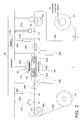
FIG. 3 shows an example of a splicing device equipped with the sensor module pertaining to an embodiment; -
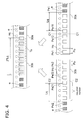
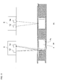
FIG. 4 is a diagram illustrating empty pockets that are necessary for tape splicing; -
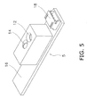
FIG. 5 is an oblique view of the sensor module pertaining to an embodiment; -
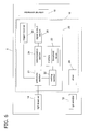
FIG. 6 is a function block diagram of the sensor module pertaining to an embodiment; -
FIG.7 is a graph of an example of displacement that varies when the carrier tape is moved continuously; -
FIG. 8 is a diagram illustrating that displacement fluctuates greatly in a pocket with a component; -
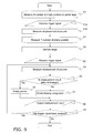
FIG. 9 is a flowchart of the flow of processing in detection performed by a sensor module; -
FIG. 10 is a flowchart of the flow of operation of the controller of a splicing device; -
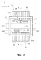
FIG. 11 is a plan view of the component mounting device pertaining to an embodiment; -
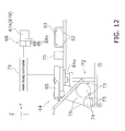
FIG. 12 is a partial cross section of the component mounting device pertaining to an embodiment; -
FIG. 13 is a diagram illustrating the configuration of the tape feeder pertaining to an embodiment; -
FIG. 14 is a diagram illustrating a tape feed mechanism in the tape feeder pertaining to an embodiment; and -
FIG. 15 is a flowchart of the flow of operation of the controller in the component mounting device pertaining to an embodiment. - An embodiment of the present invention will now be described through reference to the drawings. In the drawings referred to below, members that are the same or equivalent will be numbered the same.
- A splicing device is a device that joins pieces of the carrier tape Tc shown in
FIGS. 1 and 2 . As shown inFIG. 1 , the carrier tape Tc is formed in a slender shape with a specific width, and a plurality of pockets Pk are spaced apart at a specific pitch in the lengthwise direction. These pockets Pk hold components e that are to be mounted on a circuit board. The components are usually electronic components, so in the following description they will be referred to as electronic components e. The upper part of the pockets Pk is open. As shown inFIG. 2 , the upper part of the pockets Pk is covered by top tape Tt affixed to the surface of the carrier tape Tc. - Feed holes Hc are provided on one side in the width direction of the carrier tape Tc. The pitch spacing Pc of the feed holes Hc is set to a specific value according to IEC60286-3 ed. 5.0 or another such standard. The pitch spacing Pc of the feed holes Hc is set by standard to be the same as the pitch spacing Pp of the pockets, or to be a specific multiple of the pitch spacing Pp. The positional relation between the feed holes Hc and the pockets Pk is similarly set at the pitch spacing Pp of the various pockets. Therefore, as long as the pitch spacing Pp of the pockets Pk is known, the device that moves the carrier tape Tc can estimate where the pockets are located from the amount of movement fo the feed holes Hc.
- The carrier tape Tc is usually wound onto a reel in order to attach it to the tape feeder of a component mounting device. Therefore, the splicing device is configured so that the end of the carrier tape wound onto the current reel mounted to the current tape feeder is connected to the start of the carrier tape wound onto the next reel that will replace the current one.
-
FIG. 3 is an example of asplicing device 1 equipped with the sensor module pertaining to this embodiment. Thesplicing device 1 comprises a firsttape feed mechanism 42a, afirst sensor module 5a, afirst cutting mechanism 44a, a firstmovable conveyance path 46a, afirst disposal site 48a, afirst positioning mechanism 50a, a secondtape feed mechanism 42b, asecond sensor module 5b, asecond cutting mechanism 44b, a secondmovable conveyance path 46b, asecond disposal site 48b, asecond positioning mechanism 50b, atape splicing mechanism 52, and acontroller 40. InFIG. 3 , the two pieces of carrier tape Tc that will be spliced by thesplicing device 1 are shown as thefirst carrier tape 30a and thesecond carrier tape 30b. Also, the current reel is shown as thereel 32 and the next reel as thereel 34 inFIG. 3 . - The first
tape feed mechanism 42a feeds thefirst carrier tape 30a to a first cutting position P2. The first cutting position P2 is the position where thefirst cutting mechanism 44a (discussed below) cuts thefirst carrier tape 30a. The firsttape feed mechanism 42a is constituted by a sprocket that engages with the feed holes Hc of thefirst carrier tape 30a, and a motor, a gear, etc., that controls the rotation of this sprocket. - The
first sensor module 5a includes an optical displacement sensor. Thefirst sensor module 5a tests the pocket Pk of thefirst carrier tape 30a that is fed in from the firsttape feed mechanism 42a (hereinafter this pocket will be referred to as the first pocket Pk1), using a first trigger signal S1 a sent in from thecontroller 40 as a trigger. Thefirst sensor module 5a then determines whether or not this first pocket Pk1 is holding an electronic component e. The top tape Tt of thefirst carrier tape 30a is preferably transparent so that thefirst sensor module 5a, which is an optical displacement sensor, can make this determination. The place where thefirst sensor module 5a tests the first pocket Pk1 is called the first tape testing position P1. The first tape testing position P1 is a measurement region in which thefirst sensor module 5a can measure displacement. That is, the first pocket Pk1 of thefirst carrier tape 30a arrives at the first tape testing position P1 before it arrives at the first cutting position P2. Thefirst sensor module 5a sends a first output signal S1 b indicating the determination result for the first pocket Pk1 to thecontroller 40. The configuration and operation of thefirst sensor module 5a will be described in detail below. - The
first cutting mechanism 44a cuts thefirst carrier tape 30a at the first cutting position P2. Thefirst cutting mechanism 44a includes, for example, a cutter and a pressing member that is used for fixing thefirst carrier tape 30a. Thefirst cutting mechanism 44a is driven by a drive signal from thecontroller 40. - The first
movable conveyance path 46a sends to thefirst disposal site 48a the portion of thefirst carrier tape 30a that has been cut off by thefirst cutting mechanism 44a and is no longer needed. The firstmovable conveyance path 46a then sends to a tape splicing position P5 thefirst carrier tape 30a that has been cut by thefirst cutting mechanism 44a and is to be spliced with thesecond carrier tape 30b. The firstmovable conveyance path 46a is constituted, for example, by a movable member that is driven by a solenoid or the like. - The
first positioning mechanism 50a positions the cutfirst carrier tape 30a at the tape splicing position P5. The cutfirst carrier tape 30a is butted up against the cutsecond carrier tape 30b at the tape splicing position. Thefirst positioning mechanism 50a fixes thefirst carrier tape 30a when thefirst carrier tape 30a and thesecond carrier tape 30b are being spliced. For example, thefirst positioning mechanism 50a is a mechanism that clamps thefirst carrier tape 30a with members including a positioning pin and a positioning hole from above and below. - The second
tape feed mechanism 42b feeds thesecond carrier tape 30b to a second cutting position P4. The second cutting position P4 is the position where thesecond cutting mechanism 44b cuts thesecond carrier tape 30b. The secondtape feed mechanism 42b is constituted by a sprocket that engages with the feed holes Hc of thesecond carrier tape 30b, and a motor, a gear, etc., that controls the rotation of this sprocket. - The
second sensor module 5b includes an optical displacement sensor. Thesecond sensor module 5b tests the pocket Pk of thesecond carrier tape 30b that is fed in from the secondtape feed mechanism 42b (hereinafter this pocket will be referred to as the second pocket Pk2), using a second trigger signal S2a sent in from thecontroller 40 as a trigger. Thesecond sensor module 5b then determines whether or not this second pocket Pk2 is holding an electronic component e. The top tape Tt of thesecond carrier tape 30b is preferably transparent so that thesecond sensor module 5b, which is an optical displacement sensor, can make this determination. The place where thesecond sensor module 5b tests the second pocket Pk2 is called the second tape testing position P3. The second tape testing position P3 is a measurement region in which thesecond sensor module 5b can measure displacement. The second tape testing position P3 is located in the upper side than the second cutting position P4. That is, the second pocket Pk2 of thesecond carrier tape 30b arrives at the second tape testing position P3 before it arrives at the second cutting position P4. Thesecond sensor module 5b sends a second output signal S2b indicating the determination result for the second pocket Pk2 to thecontroller 40. The configuration and operation of thesecond sensor module 5b will be described in detail below. - The
second cutting mechanism 44b cuts thesecond carrier tape 30b at the second cutting position P4. Thesecond cutting mechanism 44b includes, for example, a cutter and a pressing member that is used for fixing thesecond carrier tape 30b. Thesecond cutting mechanism 44b is driven by a drive signal from thecontroller 40. - The second
movable conveyance path 46b sends to thesecond disposal site 48b the portion of thesecond carrier tape 30b that has been cut off by thesecond cutting mechanism 44b and is no longer needed. The secondmovable conveyance path 46b then sends to the tape splicing position P5 thesecond carrier tape 30b that has been cut by thesecond cutting mechanism 44b and is to be spliced with thefirst carrier tape 30a. The secondmovable conveyance path 46b is constituted, for example, by a movable member that is driven by a solenoid or the like. - The
second positioning mechanism 50b positions the cutsecond carrier tape 30b at the tape splicing position P5. Thesecond positioning mechanism 50b fixes thesecond carrier tape 30b when thefirst carrier tape 30a and thesecond carrier tape 30b are being spliced. For example, thesecond positioning mechanism 50b is a mechanism that clamps thesecond carrier tape 30a with members including a positioning pin and a positioning hole from above and below. - The
tape splicing mechanism 52 splices thefirst carrier tape 30a and thesecond carrier tape 30b with splicing tape Ts1 and Ts2 at the tape splicing position P5.FIG. 3 shows thetape splicing mechanism 52 as including anupper splicing mechanism 52a and alower splicing mechanism 52b, but thetape splicing mechanism 52 may include just theupper splicing mechanism 52a or thelower splicing mechanism 52b. Theupper splicing mechanism 52a, for example, affixes from above the fixedfirst carrier tape 30a andsecond carrier tape 30b by pressing through the gap between thefirst positioning mechanism 50a and thesecond positioning mechanism 50b. Thelower splicing mechanism 52b, for example, affixes from below the fixedfirst carrier tape 30a andsecond carrier tape 30b by pressing through the gap between thefirst positioning mechanism 50a and thesecond positioning mechanism 50b. Other than this, thetape splicing mechanism 52 may insert a single piece of splicing tape corresponding to the positioning pins of thefirst positioning mechanism 50a and thesecond positioning mechanism 50b between thefirst positioning mechanism 50a and thefirst carrier tape 30a and between thesecond positioning mechanism 50b and thesecond carrier tape 30b, and may affix by pressing from above and below with thefirst positioning mechanism 50a and thesecond positioning mechanism 50b. - The
controller 40 controls the firsttape feed mechanism 42a, thefirst cutting mechanism 44a, the firstmovable conveyance path 46a, thefirst positioning mechanism 50a, the secondtape feed mechanism 42b, thesecond cutting mechanism 44b, the secondmovable conveyance path 46b, thesecond positioning mechanism 50b, and thetape splicing mechanism 52. Thecontroller 40 comprises amemory 40a. Tape feed patterns corresponding to the shapes of various carrier tapes are stored in thememory 40a. Thefirst carrier tape 30a and thesecond carrier tape 30b can be fed at the desired feed rate and feed pitch by inputting a tape standard (the pitching spacing Pp of the pockets Pk) from the worker. - Therefore, the
controller 40 can feed thefirst carrier tape 30a at the pitch of the first pocket Pk1, matching the center of the first pocket Pk1 to the first tape testing position P1, on the basis of the specifications of the carrier tape Tc mentioned above. Thecontroller 40 can detect whether the center of the first pocket Pk1 is aligned with the first tape testing position P1 on the basis of a signal from a sensor mounted to the firsttape feed mechanism 42a (such as an encoder that senses the rotational angle of the motor). On the basis of this sensing result, thecontroller 40 sends thefirst sensor module 5a the first trigger signal S1 a indicating that the center position of the first pocket Pk1 has reached the first tape testing position P1. - Similarly, the
controller 40 can feed thesecond carrier tape 30b at the pitch of the second pocket Pk2, matching the center of the second pocket Pk2 to the second tape testing position P3. Thecontroller 40 can detect whether the center of the second pocket Pk2 is aligned with the second tape testing position P3 on the basis of a signal from a sensor mounted to the secondtape feed mechanism 42b. On the basis of this sensing result, thecontroller 40 sends thesecond sensor module 5b the second trigger signal S2a indicating that the center position of the second pocket Pk2 has reached the second tape testing position P3. - Furthermore, upon receiving the first output signal S1b indicating that an electronic component e is held in the first pocket Pk1, the
controller 40 drives the firsttape feed mechanism 42a so that a first portion of thefirst carrier tape 30a, which is a portion of the first pockets Pk1 between the pocket located a specific number on the tape splicing position P5 side from the pocket determined to have the electronic component e and the pocket located (the specific number + 1) on the tape splicing position P5 side, will arrive at the first cutting position P2. When the first portion reaches the first cutting position P2, thecontroller 40 drives thefirst cutting mechanism 44a to cut thefirst carrier tape 30a. Thecontroller 40 then drives the firsttape feed mechanism 42a and the firstmovable conveyance path 46a to feed the cutfirst carrier tape 30a up to the tape splicing position P5. - Also, upon receiving the second output signal S2b indicating that an electronic component is held in the second pocket Pk2, the
controller 40 drives the secondtape feed mechanism 42b so that a second portion of thesecond carrier tape 30b, which is a portion of the second pocket Pk2 between the pocket located a specific number on the tape splicing position P5 side from the pocket in which the electronic component e was determined to be present, and the pocket located (the specific number + 1) on the tape splicing position P5 side, will arrive at the second cutting position P4. When the second portion reaches the second cutting position P4, thecontroller 40 drives thesecond cutting mechanism 44b to cut thesecond carrier tape 30b. Thecontroller 40 then drives the secondtape feed mechanism 42b and the secondmovable conveyance path 46b to feed the cutsecond carrier tape 30b up to the tape splicing position P5. Finally, thecontroller 40 drives thefirst positioning mechanism 50a, thesecond positioning mechanism 50b, and thetape splicing mechanism 52 to splice thefirst carrier tape 30a and thesecond carrier tape 30b. - The above-mentioned "specific number" is found from the pitch dp1 of the first pocket Pk1, the pitch dp2 of the second pocket Pk2, and the required length 2 x Lq of the splicing tape Ts.
FIG. 4 illustrates tape splicing. InFIG. 4 , the required length 2 x Lq of the splicing tape Ts is a length that is sufficient so that thefirst carrier tape 30a and thesecond carrier tape 30b will not separate and the splicing position will not shift when the splicing tape Ts is being affixed. This required length is found experimentally, and depends on the width and the material of the carrier tape Tc, the material of the top tape Tt, and the material of the splicing tape Ts. If we assume that splicing tape Ts of the same length Lq is used for thefirst carrier tape 30a and thesecond carrier tape 30b, and that the pitch dp1 of the first pocket Pk1 and the pitch dp2 of the second pocket Pk2 are both Pp, the required number N is found from the followingFormula 1.
- (Where (a mod b) is the remainder of dividing a by b.)
- When the (required number) and the (required number + 1) are thus found, as shown in
FIG. 4 , thecontroller 40 cuts thefirst carrier tape 30a along a cutting line C1-C1, which is a portion of the first pocket Pk1 between a pocket Pe11 located a specific number on the tape splicing position P5 side from the pocket Pe1 where an electronic component e was determined to be present, and a pocket Pe12 located (the specific number + 1) on the tape splicing position P5 side. Also, thecontroller 40 cuts thesecond carrier tape 30b along a cutting line C2-C2, which is a portion of the second pocket Pk2 between a pocket Pe21 located a specific number on the tape splicing position P5 side from the pocket Pe2 where an electronic component e was determined to be present, and a pocket Pe22 located (the specific number + 1) on the tape splicing position P5 side. The specific number may be the same as the required number and may be bigger than the required number. - Next, the
first sensor module 5a and thesecond sensor module 5b will be described in detail. Since thefirst sensor module 5a and thesecond sensor module 5b are the same module, they will be referred to as thesensor module 5 below.FIG. 5 is an oblique view of thesensor module 5.FIG. 6 is a function block diagram of thesensor module 5. - Referring to
FIG. 5 , thesensor module 5 has alight emitter 12, alight receiver 14, asubstrate 16, and anexternal connector 18. As shown inFIG. 6 , part of the circuits of thelight emitter 12 and thelight receiver 14, aprocessing circuit 20, and adriver 29 are mounted on thesubstrate 16. Theprocessing circuit 20 is typically installed in a microcomputer. Thedriver 29 may be installed in the same microcomputer as theprocessing circuit 20, or may be installed in a different microcomputer. Theprocessing circuit 20 has anarithmetic section 21, asetting section 22, amemory 23, adetermination section 24, atrigger receiver 25, and asignal output section 26. - The
sensor module 5 has an optical displacement sensor formed by thelight emitter 12, thelight receiver 14, and thearithmetic section 21. Specifically, thelight emitter 12 emits light, and thelight receiver 14 receives light that has been emitted by the light emitter and reflected by an object. Thearithmetic section 21 computes the displacement of an object from the intensity of the light received by the light receiver.FIG. 5 shows an example of a reflecting type of optical displacement sensor, but a transmitting type of displacement sensor may be used instead. In that case, thelight receiver 14 is disposed opposite thelight emitter 12 and receives light that has been emitted by thelight emitter 12 and transmitted by the object. - The
light emitter 12 typically comprises a light emitting element, a first lens, and a current supply circuit. The light emitting element is a light emitting diode, for example. The first lens converges the light emitted by the light emitting element in a specific measurement region. The current supply circuit supplies current to the light emitting element when a drive signal is received from thedriver 29. Thedriver 29 supplies drive voltage to the current supply circuit steadily or at regular intervals. Consequently, thelight emitter 12 emits light steadily or at regular intervals. Thelight receiver 14 typically comprises a light receiving element, a second lens, a current-voltage conversion circuit, an amplifier, and an A/D converter. The light receiving element is a photodiode, for example. The second lens converges light from an object toward the light receiving element. The current-voltage conversion circuit converts optical current from the light receiving element into voltage. The amplifier amplifies the converted voltage. The A/D converter converts the amplified voltage into a digital value. The current supply circuit, the current-voltage conversion circuit, the amplifier, and the A/D converter are typically mounted on thesubstrate 16. The hardware configurations given above for thelight emitter 12 andlight receiver 14 are merely examples, and any hardware may be used as long as it has the precision to measure the electronic components e and the pockets Pk of the carrier tape Tc. - The
trigger receiver 25 receives trigger signals from thecontroller 40 via theexternal connector 18 from a carrier tape feed mechanism (here, thecontroller 40 of the splicing device 1). The above-mentioned first trigger signal S1 a and second trigger signal S2a are trigger signals of the same format. These trigger signals indicate that the measurement region of the sensor has received the center position of a pocket Pk. More specifically, a trigger signal is a pulse wave in which high voltage results when the measurement region of the sensor has received the center position of a pocket Pk, and low voltage results when the measurement region of the sensor has not received the center position of a pocket Pk. Thetrigger receiver 25 actuates thearithmetic section 21 when the signal changes from low voltage to high voltage. - The
arithmetic section 21 computes displacement by measuring optical current from the light emitting element of thelight receiver 14 upon being actuated by thetrigger receiver 25. When the arithmetic section is actuated is when the center of the first pocket Pk1 (or the second pocket Pk2) arrives at the first tape testing position P1 (or the second tape testing position). Therefore, when thelight emitter 12 emits light at the first pocket Pk1 (or the second pocket Pk2) of thefirst carrier tape 30a (or thesecond carrier tape 30b), thearithmetic section 21 calculates displacement from the intensity of the light received by thelight receiver 14. To put this another way, thearithmetic section 21 computes displacement from the intensity of the light received by the light receiver when thetrigger receiver 25 has received a trigger signal. - We will now explain the reason why the
arithmetic section 21 calculates displacement when the center of the first pocket Pk1 (or the second pocket Pk2) matches up with the first tape testing position P1 (or the second tape testing position P3).FIG. 7 is a graph showing an example of displacement that changes when the carrier tape is moved continuously. InFIG. 7 , the center positions of pockets Pk that are not holding electronic components e (empty pockets) are at A, B, and C, and the center positions of pockets Pk that do hold electronic components e (pockets having components) are at D and E. - As shown in
FIG. 8(a) , with a pocket having a component, when the measurement region of the sensor is located in an edge region of the pocket Pk, the light emitted from thelight emitter 12 will be reflected at various places, such as the edge of a pocket Pk (shown by a dotted line), the bottom of a pocket Pk (shown by a straight line), or the edge of an electronic component e (shown by a one-dot chain line), and this light interferes. The interfering light is incident on thelight receiver 14. P and Q inFIG. 7 are signals when light that has been intensified by interference is incident on thelight receiver 14. R and S inFIG. 7 are signals when light that has been weakened by interference is incident on thelight receiver 14, or when displacement has increased because the measurement region of the sensor is located at the bottom of the pocket Pk. Since displacement thus fluctuates greatly at the edge regions of the pockets Pk, the edge regions of the pockets Pk are not suited to identifying whether a pocket is empty or has a component. - Meanwhile, as shown in
FIG. 8(b) , at the center position of a pocket Pk, only light from the electronic component e is reflected, or only light from the bottom of the pocket Pk is reflected. Accordingly, stable output tends to be obtained, as indicated by the small circles and small triangles inFIG. 7 . Therefore, in this embodiment, thearithmetic section 21 calculates displacement when the center of the first pocket Pk1 (or the second pocket Pk2) matches up with the first tape testing position P1 (or the second tape testing position). - The
setting section 22 statistically processes displacement obtained when light is emitted by the light emitter and received by the light receiver, for the plurality of first pockets Pk1 (or second pockets Pk2) in thefirst carrier tape 30a (or thesecond carrier tape 30b). Thesetting section 22 then sets a first range (or second range) for identifying empty pockets. The first range here refers to the range set by thefirst sensor module 5a, and the second range refers to the range set by thesecond sensor module 5b. The range is divided into a first range and a second range only to distinguish between the range set by thefirst sensor module 5a and the range set by thesecond sensor module 5b, and the processing performed by thesetting section 22 is the same. - Next, the specific processing performed by the
setting section 22 and thecontroller 40 will be described. Empty pockets are disposed continuously at the front and rear ends of the carrier tape Tc wound onto a reel, as spaces for affixing the splicing tape. Therefore, the measurement result for the empty pocket (an example of a predetermined empty pocket) located at the front end of the carrier tape Tc can be utilized in the setting of the first range. Thecontroller 40 sends a command prompting the actuation of the setting section in addition to the above-mentioned trigger signal, which allows thesetting section 22 to set a threshold value for determining the first range, on the basis of the result calculated by thearithmetic section 21. Thesetting section 22 may count how many times the trigger signal is at high voltage, and operate only after the first M number of times. In this case, the integer M expressing the number of times should be stored ahead of time in thememory 23. The first range is found from the standard deviation σ and the average value da for displacement in a plurality of empty pockets. More specifically, the first range is preferably a range within n multiples of the standard deviation σ and the average value da for displacement in a plurality of empty pockets. InFIG. 7 , the boundary of the first range (the second range in thesecond sensor module 5b) when n is 4 is shown by a dotted line. As shown inFIG. 7 , empty pockets can be distinguished from pockets that have a component by setting the first range in this way. - Next, the optimal value of n will be discussed. Table 1 shows the detection accuracy when an electronic component measuring 0.4 x 0.2 mm was identified in the first range when n was varied. Table 2 shows the detection accuracy when an electronic component measuring 0.6 x 0.3 mm was identified in the first range when n was varied. Table 3 shows the detection accuracy when an electronic component measuring 1.0 x 0.5 mm was identified in the first range when n was varied. Table 4 shows the detection accuracy when an electronic component measuring 1.6 x 0.8 mm was identified in the first range when n was varied. Tables 1 to 4 give the values obtained in a simulation using actual measurement results.
Table 1 Threshol d 1σ 2σ 3σ 4σ 5σ 6σ 7σ FPR 0.00% 0.00% 0.00% 0.00% 0.00% 0.01% 0.05% FNR 15.87% 2.38% 0.13% 0.00% 0.00% 0.00% 0.00% Table 2 Threshol d 1σ 2σ 3σ 4σ 5σ 6σ 7σ FPR 0.00% 0.00% 0.00% 0.00% 0.00% 0.00% 0.00% FNR 15.87% 2.38% 0.13% 0.00% 0.00% 0.00% 0.00% Table 3 Threshol d 1σ 2σ 3σ 4σ 5σ 6σ 7σ FPR 0.00% 0.00% 0.00% 0.00% 0.00% 0.00% 0.00% FNR 15.87% 2.38% 0.13% 0.00% 0.00% 0.00% 0.00% Table 4 Threshol d 1σ 2σ 3σ 4σ 5σ 6σ 7σ FPR 0.00% 0.00% 0.00% 0.00% 0.00% 0.00% 0.00% FNR 15.87% 2.38% 0.13% 0.00% 0.00% 0.00% 0.00% - The above-mentioned FPR stands for false positive rate, and indicates the rate at which a pocket is detected as an empty pocket even though it actually contains a component. FNR stands for false negative rate, and indicates the rate at which a pocket is not detected as an empty pocket (that is, at which it is detected as containing a component) even though it is actually an empty pocket. As is clear from Tables 1 to 4, the detection accuracy is highest when n = 4 or n = 5. When a pocket is detected as an empty pocket even though it actually contains a component, this is linked to an increase in the frequency at which components are discarded, and is therefore undesirable. In view of this, the first range is most preferably determined to be a range within four times the standard deviation σ and the average value for the measurement result of a plurality of empty pockets (the measured amount of displacement).
- The
setting section 22 stores threshold values that define the first range (such as da - 4σ, da + 4σ) in thememory 23. Alternatively, thesetting section 22 may store the value of the standard deviation σ and the average value da. Therefore, thememory 23 holds threshold values that define the first range and are used to identify empty pockets. - The
determination section 24 refers to the threshold values stored in thememory 23, or to data defining the first range, and determines whether a pocket Pk corresponding to the displacement calculated by thearithmetic section 21 is an empty pocket or a pocket having a component. More specifically, thedetermination section 24 determines the pocket Pk to be an empty pocket when the displacement calculated by thearithmetic section 21 is within the first range. Thedetermination section 24 determines the pocket Pk to be a pocket having a component when the displacement calculated by thearithmetic section 21 is outside the first range. That is, thedetermination section 24 determines that an electronic component e is present in this pocket Pk. - The
signal output section 26 outputs the determination result from thedetermination section 24 to an external device (here, thecontroller 40 of the splicing device 1). This output signal is, for example, a rectangular wave in which the voltage is high when the pocket Pk is a pocket having a component, and the voltage is low when the pocket Pk is an empty pocket. - Next, we will describe the flow of processing performed by this
sensor module 5 to detect components in a carrier tape.FIG. 9 is a flowchart showing the flow of processing in the detection method used by thesensor module 5. - First, in step S1, the
sensor module 5 measures the displacement of N number (N ≥ 2) of empty pockets (an example of a predetermined empty pockets) in a carrier tape. This value of N is predetermined and stored in thememory 23. More specifically, thetrigger receiver 25 receives a trigger signal from an external device (step S1 a). Thearithmetic section 21 then measures the displacement of a pocket (step S1 b). After steps S1 a and S1 b have been repeated N number of times, thesetting section 22 sets the first range (step S2). More specifically, thesetting section 22 calculates the average value da from the N number of measurement results, and calculates the standard deviation σ. Then, thesetting section 22 sets da - nσ, da + nσ (n is preferably 4) as the threshold value for the first range. Thesetting section 22 stores the set threshold value in thememory 23. - When the setting of the first range is finished, in step S3 the
trigger receiver 25 receives a trigger signal. Then, in step S4, thearithmetic section 21 measures the displacement of the pocket (an example of an undetermined pocket) to be measured. Next, in step S5, thedetermination section 24 uses the threshold value stored in thememory 23 to determine whether or not the measured displacement is within the first range. If the measured displacement is within the first range (Yes in step S5), thedetermination section 24 determines that the pocket being measured is an empty pocket (step S6). If the measured displacement is outside the first range (No in step S5), thedetermination section 24 determines that the pocket being measured is a pocket having a component (step S7). That is, thedetermination section 24 determines that there is a component in the pocket being measured. Then, thesignal output section 26 outputs an output signal indicating the determination result to an external device (step S8). Next, thetrigger receiver 25 confirms whether or not another trigger signal has been received (step S9). If another trigger signal has not been received (No in step S9), the processing is ended, but if another trigger signal has been received (Yes in step S9), the flow returns to step S4. - Next, the specific operation of the
controller 40 pertaining to this embodiment will be described.FIG. 10 is a flowchart of the flow of operation of thecontroller 40 of thesplicing device 1. - In steps S10 and S11, the
first carrier tape 30a and thesecond carrier tape 30b are inserted. Thecontroller 40 then drives the firsttape feed mechanism 42a and the secondtape feed mechanism 42b to feed the tape so that the center position of the first pocket Pk1 of thefirst carrier tape 30a will go to the first tape testing position P1, and the center position of the second pocket Pk2 will go to the second tape testing position P3 (steps S12 and S13). Once the tape feed is finished, thecontroller 40 outputs the first trigger signal S1 a and the second trigger signal S2a to thefirst sensor module 5a and thesecond sensor module 5b (steps S14 and S15). Thecontroller 40 then inputs the first output signal S1 b and the second output signal S2b, which are the determination results for thefirst sensor module 5a and thesecond sensor module 5b (steps S16 and S17). Thecontroller 40 determines whether or not the pockets located at the first tape testing position P1 and the second tape testing position P3 are empty pockets on the basis of the first output signal S1 b and the second output signal S2b (steps S18 and S19). - If it is an empty pocket in step S18 (Yes in step S18), the flow returns to step S12. If it is an empty pocket in step S19 (Yes in step S19), the flow returns to step S12. If it is not an empty pocket in step S19 (No in step S18), the
controller 40 drives the firsttape feed mechanism 42a so that the first portion of thefirst carrier tape 30a, which is a portion of the first pocket Pk1 between the pocket located a specific number on the tape splicing position P5 side from the pocket in which the electronic component e was determined to be present, and the pocket located (the specific number + 1) on the tape splicing position P5 side, will arrive at the first cutting position P2 (step S20). If it is not an empty pocket in step S19 (No in step S19), thecontroller 40 drives the secondtape feed mechanism 42b so that the second portion of thesecond carrier tape 30b, which is a portion of the second pocket Pk2 between the pocket located a specific number on the tape splicing position P5 side from the pocket in which the electronic component e was determined to be present, and the pocket located (the specific number + 1) on the tape splicing position P5 side, will arrive at the second cutting position P4 (step S21). - After step S20 is finished, the
controller 40 drives thefirst cutting mechanism 44a to cut thefirst carrier tape 30a (step S22), and drives thefirst positioning mechanism 50a to position the cutfirst carrier tape 30a at the tape splicing position P5 (step S24). After step S21 is finished, thecontroller 40 drives thesecond cutting mechanism 44b to cut thesecond carrier tape 30b (step S23), and drives thesecond positioning mechanism 50b to position the cutsecond carrier tape 30b at the tape splicing position P5 (step S25). Finally, thecontroller 40 drives thetape splicing mechanism 52 to splice thefirst carrier tape 30a and thesecond carrier tape 30b (S26). -
FIG. 11 is a plan view of thecomponent mounting device 3 pertaining to an embodiment of the present invention, andFIG. 12 is a partial cross section of thecomponent mounting device 3 pertaining to an embodiment of the present invention.FIG. 12 partially shows the A-A cross section inFIG. 11 . InFIG. 11 ,conveyance paths 62 are installed in the X direction (the substrate conveyance direction) in the center of abase 61. Theconveyance paths 62 convey asubstrate 63 that has come in from the upstream side, and positions it on a mounting stage.Component supply section 64 are disposed on both sides of theconveyance paths 62, and a plurality oftape feeders 65 are arranged on each of thecomponent supply section 64. Thetape feeders 65 pitch-feed carrier tape that supports electronic components, thereby supplying electronic components to pickup positions with placement heads (discussed below). - Y axis tables 66A and 66B are provided to both ends of the upper face of the
base 61, and X axis tables 67A and 67B are provided spanning the Y axis tables 66A and 66B. When the Y axis table 66A is driven, the X axis table 67A moves horizontally in the Y direction, and when the Y axis table 66B is driven, the X axis table 67B moves horizontally in the Y direction.Substrate recognition cameras 69 that move integrally with placement heads 68 are mounted on the X axis tables 67A and 67B. - The Y axis table 66A, the X axis table 67A, the Y axis table 66B, and the axis table 67B are combined and driven to move the placement heads 68 horizontally, electronic components are picked up from the
component supply section 64 thereof bysuction nozzles 68a (seeFIG. 12 ), and these electronic components are mounted on thesubstrate 63 positioned on theconveyance paths 62. The operation of the placement heads 68 is controlled by amain body controller 76. Thesubstrate recognition cameras 69 that have moved over thesubstrate 63 image and recognize thesubstrate 63.Component recognition cameras 70 andnozzle holders 71 are provided in between thecomponent supply section 64 and theconveyance paths 62. - When the placement heads 68 that have removed the electronic components from the
component supply section 64 move to thesubstrate 63 positioned on the mounting stage, the electronic components held by thesuction nozzles 68a are moved in the X direction above thecomponent recognition cameras 70, and thecomponent recognition cameras 70 image the electronic components held by thesuction nozzles 68a. The imaging results are subjected to recognition processing by a recognition processor (not shown), so that the positions of the electronic components are recognized while they are being held by thesuction nozzles 68a, and the type of electronic components is identified. Thenozzle holders 71 perform a nozzle replacement operation in which a plurality of types ofsuction nozzles 68a are held in a specific orientation and the placement heads 68 access thenozzle holders 71, the result being that the nozzles are replaced according to the type of electronic component in the placement heads 68. - The structure of the
component supply section 64 will now be described. As shown inFIG. 12 , afeeder base 64a is provided for mounting a plurality oftape feeders 65 to thecomponent supply section 64. Thetape feeders 65 are disposed on thecomponent supply section 64 by afeeder mounting truck 72. Thetruck 72 is provided withreel support components 73 that supporttape reels 74 that holdcarrier tapes 75 in a wound state. Thereel support components 73 are equipped with support rollers for rotatably supporting thetape reels 74, and thecarrier tapes 75 can be pulled out by rotating thetape reels 74 disposed on thecomponent supply section 64. -
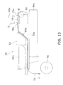
FIG. 13 illustrates the structure of thetape feeders 65 in an embodiment of the present invention. As shown inFIG. 13 , atape travel path 65b over which thecarrier tape 75 travels is provided to aframe member 65a mounted to thefeeder base 64a. Electronic components e are held in pockets Pk, which are concave components used to hold components and formed at a regular pitch in thecarrier tape 75, and the upper faces of the pockets Pk are covered by the top tape Tt. - The
carrier tape 75 that has been pulled out from thetape reel 74 is guided from the rear end of theframe member 65a and fed over the upper face of theframe member 65a to the downstream side (the right side inFIG. 13 ). In the component supply operation in which electronic components are continuously supplied while thecarrier tape 75 is fed, if thecarrier tape 75 wound around thetape reel 74 should run out, the tape splicing discussed in the first embodiment is carried out.FIG. 13 shows a seam J formed in this tape splicing. - A
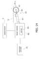
sprocket 81 driven by arotational drive mechanism 80 is provided to the upper part on the downstream end of theframe member 65a. As shown inFIG. 14 , feed pins 81 a that engage with feed holes Hc made at a regular pitch in the carrier tape 75 (seeFIG. 1 ) are provided to thesprocket 81. Therotational drive mechanism 80 is configured so that thesprocket 81 is rotationally driven via abevel gear 84 by amotor 83 in which the amount of rotation can be controlled. Thesprocket 81 is rotated by driving themotor 83, and this feeds thecarrier tape 75 in the downstream direction. Thesprocket 81 and therotational drive mechanism 80 are a tape feed mechanism for the pitch feed of thecarrier tapes 75 along thetape travel path 65b. - The
motor 83 is controlled by afeeder controller 85, and thefeeder controller 85 is controlled by themain body controller 76. Thefeeder controller 85 is equipped with amemory 86, and themain body controller 76 can write various tape feed patterns to thememory 86. Thecarrier tape 75 can be fed at the desired feed rate and feed pitch by having themain body controller 76 output an operational command to thefeeder controller 85. That is, themain body controller 76 controls not only the placement heads 68, but also thetape feeders 65. Consequently, as will be discussed below, in the process of repeatedly subjecting thecarrier tape 75 to intermittent pitch feed at a specific pitch, it is possible for thecarrier tapes 75 to be fed in a single feed operation by a batch feed amount of a specific length. - The
feeder controller 85 is connected to the above-mentionedsensor module 5. Thefeeder controller 85 refers to various tape feed patterns in thememory 86 on the basis of operational commands from themain body controller 76. Thefeeder controller 85 then senses the timing at which the center portion of the pocket Pk reaches the component testing position, which is the measurement region of thesensor module 5, on the basis of the specifications of the above-mentioned carrier tape Tc. The component testing position will be discussed below. Thefeeder controller 85 then outputs to thesensor module 5 a trigger signal that indicates the sensed timing. Thearithmetic section 21 of thesensor module 5 computes displacement from the intensity of the light received by thelight receiver 14 when the trigger signal is received. That is, it computes displacement from the intensity of the light received by thelight receiver 14 when the pocket Pk reaches the component testing position. The trigger signal may be the same as the one in the first embodiment. In the following description, thefeeder controller 85 and themain body controller 76 will be collectively referred to as a controller. - The side of the
sprocket 81 where the tape comes to is the component takeoff position where the electronic components e in the pockets Pk are picked up by thesuction nozzles 68a of the placement heads 68. Anupper guide component 78 that covers and guides above thecarrier tape 75 near the component takeoff position is provided to the upper face of the downstream portion of theframe member 65a. Theupper guide component 78 has asuction opening 78a and acomponent testing opening 78b. Thecomponent testing opening 78b is located upstream of thesuction opening 78a. The upstream end of thecomponent testing opening 78b is provided with a top tape separator for peeling off the top tape Tt. In the process in which thecarrier tape 75 travels under theupper guide component 78, the top tape Tt is peeled off by the top tape separator and is folded back toward the upstream side. The folded-back top tape Tt is fed into atape recovery component 65c by a toptape feed mechanism 82, and recovered. - The pockets Pk exposed when the top tape Tt is peeled off are fed into the
component testing opening 78b. The above-mentionedsensor module 5 is provided above thecomponent testing opening 78b. That is, thecomponent testing opening 78b is provided directly under thesensor module 5. Thecomponent testing opening 78b is provided in the measurement region of thesensor module 5. Specifically, thecomponent testing opening 78b corresponds to the above-mentioned component testing position. Thesensor module 5 measures the center of the pockets Pk of thecarrier tape 75 by measuring displacement at a timing based on a trigger signal from thefeeder controller 85. Consequently, thesensor module 5 detects whether or not there are components in the pockets Pk. The component detection method employed by thesensor module 5 is the same as that in the first embodiment. Thesensor module 5 sends themain body controller 76 an output signal indicating the detection result related to whether or not there are components in the pockets Pk. If a measured pocket Pk is an empty pocket, there is a high probability that the measured pocket is part of the seam J. - The
suction opening 78a corresponds to the component takeoff position of thesuction nozzles 68a. Usually, the electronic components e are picked up by thesuction nozzles 68a from the pockets Pk exposed by peeling off by the top tape. However, if themain body controller 76 receives an output signal indicating that a measured pocket Pk has been determined to be an empty pocket, then when this measured empty pocket is fed into thesuction opening 78a, the movement and placement of the electronic components by the placement heads 68 is halted. - Next, the controller and the operation of the sensor module in this embodiment will now be described.
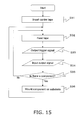
FIG. 15 is a flowchart of the flow of operation of the controller in the component mounting device pertaining to this embodiment. First, in step S31, thecarrier tape 75 is inserted into acomponent mounting device 3. Next, in step S32, themain body controller 76 and thefeeder controller 85 feed the tape so that the center position of the pockets Pk of thecarrier tape 75 goes to the component testing position (step S32). Thefeeder controller 85 then outputs a trigger signal to the sensor module 5 (step S33). After the trigger signal has been outputted, themain body controller 76 inputs an output signal indicating the determination result produced by the sensor module 5 (step S34). Themain body controller 76 determines whether or not there is a component in the pocket located at the component testing position on the basis of this output signal (step S35). If there is a component (Yes in step S35), when that pocket has reached the component removal position, themain body controller 76 drives theplacement head 68 to pick up the electronic component e with thesuction nozzle 68a, transfers the component to thesubstrate 63, and mounts it on the substrate 63 (step S36). If there is no component (No in step S35), then when that pocket reaches the component removal position, themain body controller 76 does not drive theplacement head 68, and the processing of step S32 is executed again. - Next, the effect of the
sensor modules splicing device 1 pertaining to the first embodiment, and that of thecomponent mounting device 3 pertaining to the second embodiment will be described. Thesensor modules splicing device 1, and thecomponent mounting device 3 statistically process the displacement of a plurality of empty pockets, and set a first range of displacement in which a pocket is determined to be an empty pocket. If the measured displacement of a pocket is within the first range, that pocket is determined to be an empty pocket, and if the measured displacement of the pocket is outside the first range, a component is determined to be in the pocket. With empty pockets, the amount of displacement tends to be different from that of a tape portion or pocket containing a component. Therefore, whether or not there are components in a carrier tape can be stably detected with a photosensor. - Also, the
component mounting device 3 and thesplicing device 1 feed the carrier tape so that the measurement region of thesensor modules sensor modules sensor modules - Embodiments of the present invention were described above, but the present invention is not limited to or by the above embodiments, and various modifications are possible without departing from the gist of the invention.
- The
tape splicing device 1 and thecomponent mounting device 3 discussed above are just examples, and thesensor module 5 of the present invention can be used in the same application in othertape splicing devices 1 andcomponent mounting devices 3. - In the setting of the first range, the median, the mode, or some other statistical value may be used instead of the average value da.
- In the first embodiment, the
first sensor module 5a and thesecond sensor module 5b may have a function that excludes theprocessing circuit 20, and thecontroller 40 may instead have the function of theprocessing circuit 20. Similarly, in the second embodiment, thesensor module 5 may have a function that excludes theprocessing circuit 20, and thefeeder controller 85 may instead have the function of theprocessing circuit 20. - Also, in the second embodiment, the
sensor module 5 may be disposed upstream from the position shown inFIG. 13 . Upstream from the position shown inFIG. 13 , the splicing tape Ts and the top tape Tt are not peeled off of the carrier tape Tc. Therefore, in this case, the splicing tape Ts and the top tape Tt are preferably transparent. Alternatively, thesensor module 5 is preferably able to detect changes in displacement due to the thickness of the splicing tape Ts. - The present invention provides a method that allows the presence of components in a carrier tape to be detected with a photosensor, as well as a sensor module, a splicing device, and a component mounting device that execute said method.
-
- 1
- splicing device
- 3
- component mounting device
- 5, 5a, 5b
- sensor module
Claims (15)
- A method for detecting whether there are components in a carrier tape with an optical displacement sensor, said method comprising the steps of:using the optical displacement sensor to measure the displacement of a plurality of predetermined empty pockets in the carrier tape;statistically processing the measured displacement of the predetermined empty pockets, and determining a first range of displacement;using the optical displacement sensor to measure the displacement of an undetermined pocket in the carrier tape; anddetermining the undetermined pocket to be an empty pocket if the measured displacement of the undetermined pocket is within the first range of displacement, and determining that the undetermined pocket to be a component-filled pocket if the measured displacement of the pocket is outside the first range of displacement.
- The method according to Claim 1,
wherein the optical displacement sensor receives a trigger signal from a carrier tape feed mechanism indicating that the measurement region of the optical displacement sensor has reached the center position of a first predetermined empty pocket or the undetermined pocket, and
upon receiving the trigger signal, the optical displacement sensor measures the displacement of the first predetermined empty pocket or the displacement of the undetermined pocket. - The method according to Claim 1 or 2, wherein the first range of displacement is determined by a standard deviation and an average value of the plurality of the predetermined empty pockets.
- A sensor module that includes an optical displacement sensor, for detecting the presence of components in a carrier tape, said sensor module comprising:a light emitter that emits light for a pocket in the carrier tape;a light receiver that receives the light from the light emitter;an arithmetic section that calculates displacement from an intensity of light received by the light receiver;a setting section that statistically processes displacement obtained when the light receiver receives the light from the light emitter for a plurality of predetermined empty pockets in the carrier tape, and sets a first range of displacement;a memory that stores threshold values that define the first range; anda determination section that determines an undetermined pocket to be an empty pocket if the calculated displacement is within the first range of displacement, and determines that the undetermined pocket is a component-filled pocket if the calculated displacement is outside the first range of displacement.
- The sensor module according to Claim 4, further comprising a trigger receiver that receives a trigger signal indicating that a measurement region of the displacement sensor has reached a center position of a first predetermined empty pocket or the undetermined pocket,
wherein the arithmetic section calculates the displacement from the intensity of light received by the light receiver when the trigger receiver has received the trigger signal. - The sensor module according to Claim 4 or 5, wherein the first range of displacement is defined by a standard deviation and an average value of displacement of the plurality of the predetermined empty pockets.
- A component mounting device, comprising:a tape feeder that sends a component held in an undetermined pocket of a carrier tape to a component removal position;a placement head that removes the components from the undetermined pocket and moves them for placement on a substrate; anda controller that controls the tape feeder and the placement head,wherein the tape feeder has a sensor module that includes;an optical displacement sensor,a light emitter that emits light for a pocket in the carrier tape,a light receiver that receives the light from the light emitter,an arithmetic section that calculates displacement from an intensity of light received by the light receiver when the undetermined pocket has arrived at a component testing position before arriving at the component removal position,a memory that stores threshold values that define a first range of displacement,a determination section that determines the undetermined pocket to be an empty pocket if the calculated displacement is within the first range of displacement, and determines that a component is in the undetermined pocket if the calculated displacement is outside the first range of displacement, anda signal transmitter that transmits to the controller an output signal indicating a pocket determination result produced by the determination section; and whereinupon receipt of the output signal indicating that the undetermined pocket was determined to be the empty pocket, the controller halts movement and placement by the placement head when the empty pocket is sent to the component removal position.
- The component mounting device according to Claim 7, wherein the sensor module further includes a setting section that statistically processes displacement obtained when the light receiver receives the light from the light emitter for a plurality of predetermined empty pockets in the carrier tape, and sets the first range of displacement.
- The component mounting device according to Claim 8, wherein the controller sends the sensor module a trigger signal indicating that a center position of the undetermined pocket or a first predetermined empty pocket has arrived at the component testing position,
the sensor module further includes a trigger receiver that receives the trigger signal, and
the arithmetic section calculates the displacement from the intensity of light received by the light receiver when the trigger receiver has received the trigger signal. - The component mounting device according to any of Claims 8 to 9, wherein the first range is defined by a standard deviation and an average value of displacement of the plurality of predetermined empty pockets.
- A splicing device that splices a first carrier tape and a second carrier tape, comprising:a first tape feed mechanism that feeds the first carrier tape to a first cutting position;a first sensor module that includes a first optical displacement sensor;a first cutting mechanism that cuts the first carrier tape at the first cutting position;a first positioning mechanism that positions the cut first carrier tape at a tape splicing position;a second tape feed mechanism that feeds the second carrier tape to a second cutting position;a second sensor module that includes a second optical displacement sensor;a second cutting mechanism that cuts the second carrier tape at the second cutting position;a second positioning mechanism that positions the cut second carrier tape at the tape splicing position;a tape splicing mechanism that splices the first carrier tape and the second carrier tape with splicing tape at the tape splicing position; anda controller that controls the first tape feed mechanism, the first cutting mechanism, the first positioning mechanism, the second tape feed mechanism, the second cutting mechanism, the second positioning mechanism, and the tape splicing mechanism,wherein the first sensor module includes:a first light emitter that emits light for a first pocket in the first carrier tape;a first light receiver that receives the light from the first light emitter;a first arithmetic section that calculates a first displacement from a first intensity of light received by the first light receiver when the first pocket of the first carrier tape has arrived at a first tape testing position before arriving at the first cutting position;a first memory that stores threshold values that define a first range of the first displacement;a first determination section that determines the first pocket to be a first empty pocket if the first displacement is within the first range, and determines the first pocket to be a first component-filled pocket if the first displacement is outside the first range; anda first signal transmitter that transmits to the controller a first output signal indicating the first pocket determination result produced by the first determination section,the second sensor module includes:a second light emitter that emits light for a second pocket in the second carrier tape;a second light receiver that receives the light from the second light emitter;a second arithmetic section that calculates a second displacement from a second intensity of light received by the second light receiver when the second pocket of the second carrier tape has arrived at a second tape testing position before arriving at the second cutting position;a second memory that stores threshold values that define a second range of the second displacement;a second determination section that determines the second pocket to be a second empty pocket if the second displacement is within the second range, and determines that the second pocket is a second component-filled pocket if the second displacement is outside the second range; anda second signal transmitter that transmits to the controller a second output signal indicating the second pocket determination result produced by the second determination section, andthe controller:upon receiving the first output signal indicating that the first determination section has determined that there is the first component-filled pocket, causes the first cutting mechanism to cut the first carrier tape when a first portion of the first carrier tape, which is a portion between a pocket located a specific number on the tape splicing position side from the first component-filled pocket was determined to be present, and a specific number + 1 pocket located on the tape splicing position side from the first component-filled, arrives at the first cutting position, andupon receiving the second output signal indicating that the second determination section has determined that there is the second component-filled pocket, causes the second cutting mechanism to cut the second carrier tape when a second portion of the second carrier tape, which is a portion of the second pocket between the pocket located a specific number on the tape splicing position side from the second component-filled pocket, and the specific number + 1 pocket located on the tape splicing position side from the second component-filled pocket, arrives at the second cutting position.
- The splicing device according to Claim 11, wherein the specific number is found from a pitch of the first pocket and a pitch of the second pocket, and a required length of the splicing tape.
- The splicing device according to Claim 11 or 12,
wherein the first sensor module further includes a first setting section that statistically processes the first displacement obtained when the first light receiver receives the light from the first light emitter for a first plurality of predetermined empty pockets of the first carrier tape, and sets the first range, and
the second sensor module further includes a second setting section that statistically processes the second displacement obtained when the second light receiver receives the light from the second light emitter for a second plurality of predetermined empty pockets of the second carrier tape, and sets the second range. - The splicing device according to Claim 13,
wherein the controller sends the first sensor module a first trigger signal indicating that the center position of the first pocket has arrived at the first tape testing position,
the first sensor module further includes a first trigger receiver that receives the first trigger signal,
the first arithmetic section calculates the first displacement from the first intensity of light received by the first light receiver when the first trigger receiver has received the first trigger signal,
the controller sends the second sensor module a second trigger signal indicating that the center position of the second pocket has arrived at the second tape testing position,
the second sensor module further includes a second trigger receiver that receives the second trigger signal, and
the second arithmetic section calculates the second displacement from the second intensity of light received by the second light receiver when the second trigger receiver has received the second trigger signal. - The splicing device according to any of Claims 13 to 14, wherein the first range is defined by a standard deviation and an average value of the first displacement of the first predetermined plurality of empty pockets, and
the second range is defined by a standard deviation and an average value of the second displacement of the second predetermined plurality of empty pockets.
Applications Claiming Priority (1)
| Application Number | Priority Date | Filing Date | Title |
|---|---|---|---|
| JP2014051433A JP2015176970A (en) | 2014-03-14 | 2014-03-14 | Method of detecting presence/absence of component in carrier tape, sensor module, splicing device and component packaging machine |
Publications (2)
| Publication Number | Publication Date |
|---|---|
| EP2919573A2 true EP2919573A2 (en) | 2015-09-16 |
| EP2919573A3 EP2919573A3 (en) | 2016-07-13 |
Family
ID=52434527
Family Applications (1)
| Application Number | Title | Priority Date | Filing Date |
|---|---|---|---|
| EP15151116.9A Withdrawn EP2919573A3 (en) | 2014-03-14 | 2015-01-14 | Method for detecting components in carrier tape, sensor module, splicing device, and component mounting device |
Country Status (5)
| Country | Link |
|---|---|
| US (1) | US20150258687A1 (en) |
| EP (1) | EP2919573A3 (en) |
| JP (1) | JP2015176970A (en) |
| KR (1) | KR101576856B1 (en) |
| CN (1) | CN104918478A (en) |
Families Citing this family (23)
| Publication number | Priority date | Publication date | Assignee | Title |
|---|---|---|---|---|
| JP5847926B2 (en) * | 2012-04-18 | 2016-01-27 | 富士機械製造株式会社 | Automatic splicing equipment |
| JP6322811B2 (en) * | 2014-07-28 | 2018-05-16 | パナソニックIpマネジメント株式会社 | Component mounting apparatus and component mounting method |
| JP6521991B2 (en) * | 2014-10-09 | 2019-05-29 | 株式会社Fuji | Determination method and determination device |
| WO2017098630A1 (en) * | 2015-12-10 | 2017-06-15 | 富士機械製造株式会社 | Splicing device |
| JP6603877B2 (en) * | 2016-03-09 | 2019-11-13 | パナソニックIpマネジメント株式会社 | Carrier tape component detection device and component supply device |
| WO2018042509A1 (en) * | 2016-08-30 | 2018-03-08 | 富士機械製造株式会社 | Splicing device |
| WO2018073924A1 (en) * | 2016-10-20 | 2018-04-26 | 富士機械製造株式会社 | Splicing device |
| JP6667421B2 (en) * | 2016-11-10 | 2020-03-18 | ヤマハ発動機株式会社 | Component mounting device and tape feeder |
| JP6845938B2 (en) * | 2017-09-15 | 2021-03-24 | 株式会社Fuji | Parts supply system |
| JP6875558B2 (en) * | 2018-01-17 | 2021-05-26 | 株式会社Fuji | Splicing device |
| WO2019146033A1 (en) * | 2018-01-25 | 2019-08-01 | 株式会社Fuji | Splicing device |
| CN110481841B (en) * | 2018-05-14 | 2022-08-23 | 深圳市复德科技有限公司 | Material taking and placing device and material replacing equipment with same |
| EP3860329B1 (en) * | 2018-09-27 | 2024-01-10 | Fuji Corporation | Component supply apparatus |
| CN110027735B (en) * | 2019-04-01 | 2024-01-30 | 东莞旺福电子有限公司 | Automatic change laser module and detect equipment for packing |
| CN111182780B (en) * | 2020-01-16 | 2021-06-22 | 深圳市蓝眼博科科技有限公司 | Material belt splicing machine |
| CN111301748B (en) * | 2020-02-27 | 2021-09-10 | 深圳格兰达智能装备股份有限公司 | Automatic splicing mechanism for IC chip braid and braid re-inspection machine |
| KR102132984B1 (en) * | 2020-02-27 | 2020-07-10 | 주식회사하이셈테크놀로지 | inspection apparatus for carrier tape including chip |
| JP2021166225A (en) * | 2020-04-06 | 2021-10-14 | 株式会社Fuji | Carrier tape determination device |
| JPWO2022149264A1 (en) * | 2021-01-08 | 2022-07-14 | ||
| KR102441250B1 (en) * | 2022-02-21 | 2022-09-07 | (주)네온테크 | Detection system for measuring materials lifting by laser and measuring method using the same |
| CN114509041B (en) * | 2022-04-20 | 2022-07-01 | 南通勤为半导体科技有限公司 | A on-line measuring mechanism for carrier band production |
| CN115258235B (en) * | 2022-08-02 | 2024-04-16 | 深圳市中金科五金制造有限公司 | Carrier band packing inspection control system based on image recognition |
| CN115258237B (en) * | 2022-08-11 | 2024-04-16 | 深圳市中金科五金制造有限公司 | Full-automatic electronic induction system and CCD vertical detection method thereof |
Citations (2)
| Publication number | Priority date | Publication date | Assignee | Title |
|---|---|---|---|---|
| JP2007214476A (en) | 2006-02-13 | 2007-08-23 | Matsushita Electric Ind Co Ltd | Method of mounting electronic parts |
| WO2013157109A1 (en) | 2012-04-18 | 2013-10-24 | 富士機械製造株式会社 | Automatic splicing device |
Family Cites Families (12)
| Publication number | Priority date | Publication date | Assignee | Title |
|---|---|---|---|---|
| JPS57212020A (en) * | 1981-06-25 | 1982-12-27 | Showa Electric Wire & Cable Co Ltd | Automatic tape jointing device |
| JPS63177589A (en) * | 1987-01-19 | 1988-07-21 | 三洋電機株式会社 | Automatic parts mounter |
| JPH04243757A (en) * | 1991-01-22 | 1992-08-31 | Tdk Corp | Automatic connecting device for series of chip component |
| JP4494547B2 (en) * | 1999-03-10 | 2010-06-30 | Juki株式会社 | Electronic component detector |
| JP4275258B2 (en) * | 1999-07-23 | 2009-06-10 | 富士機械製造株式会社 | Article supply device |
| US7220095B2 (en) * | 2001-05-24 | 2007-05-22 | Lyndaker David W | Self-threading component tape feeder |
| JP2005105681A (en) * | 2003-09-30 | 2005-04-21 | Toto Ltd | Human body detecting device and automatic faucet device mounted with this device |
| JP5214478B2 (en) | 2009-01-22 | 2013-06-19 | 株式会社日立ハイテクインスツルメンツ | Electronic component mounting method and electronic component mounting apparatus |
| JP5431237B2 (en) * | 2010-04-23 | 2014-03-05 | パナソニック株式会社 | Jig, sticking method |
| JP5434884B2 (en) * | 2010-10-27 | 2014-03-05 | パナソニック株式会社 | Electronic component mounting apparatus and electronic component mounting method |
| JP5940243B2 (en) * | 2010-12-28 | 2016-06-29 | ヤマハ発動機株式会社 | Electronic component mounting apparatus and electronic component mounting method |
| KR101232134B1 (en) * | 2011-11-25 | 2013-02-13 | 에스티에스 주식회사 | Carrier tape feeder for passing in chip-fee region of carrier tape |
-
2014
- 2014-03-14 JP JP2014051433A patent/JP2015176970A/en active Pending
-
2015
- 2015-01-09 KR KR1020150003704A patent/KR101576856B1/en not_active IP Right Cessation
- 2015-01-12 CN CN201510015177.3A patent/CN104918478A/en active Pending
- 2015-01-14 EP EP15151116.9A patent/EP2919573A3/en not_active Withdrawn
- 2015-01-14 US US14/597,203 patent/US20150258687A1/en not_active Abandoned
Patent Citations (2)
| Publication number | Priority date | Publication date | Assignee | Title |
|---|---|---|---|---|
| JP2007214476A (en) | 2006-02-13 | 2007-08-23 | Matsushita Electric Ind Co Ltd | Method of mounting electronic parts |
| WO2013157109A1 (en) | 2012-04-18 | 2013-10-24 | 富士機械製造株式会社 | Automatic splicing device |
Also Published As
| Publication number | Publication date |
|---|---|
| CN104918478A (en) | 2015-09-16 |
| US20150258687A1 (en) | 2015-09-17 |
| EP2919573A3 (en) | 2016-07-13 |
| KR20150107593A (en) | 2015-09-23 |
| KR101576856B1 (en) | 2015-12-14 |
| JP2015176970A (en) | 2015-10-05 |
Similar Documents
| Publication | Publication Date | Title |
|---|---|---|
| EP2919573A2 (en) | Method for detecting components in carrier tape, sensor module, splicing device, and component mounting device | |
| US8678065B2 (en) | Carrier tape feeder | |
| US9802399B2 (en) | Feeder | |
| US10165717B2 (en) | Component mounting device | |
| JP5597050B2 (en) | Substrate stop position control method and apparatus, and substrate mounting position control method | |
| WO2012056606A1 (en) | Electronic component mounting device and electronic component mounting method | |
| CN105764314B (en) | Electronic component supply device | |
| US10420268B2 (en) | Component supply system and component supply method | |
| CN109328013B (en) | Electronic component supply device, electronic component mounting device, and electronic component supply method | |
| CN105764319B (en) | Electronic component supply device and method for processing component supply tape in electronic component supply device | |
| CN105764320B (en) | Electronic component supply device and electronic component supply method | |
| EP3379913B1 (en) | Control device for component mounting machine | |
| US10939601B2 (en) | Component mounting line | |
| CN105764318B (en) | Electronic component supply device | |
| US10349570B2 (en) | Component mounter | |
| EP3731615A1 (en) | Pick-and-place device, detection device, and detection method | |
| JP6413086B2 (en) | Electronic component supply device and method of processing component supply tape in electronic component supply device | |
| KR101690581B1 (en) | Component supply unit | |
| JP6983326B2 (en) | Splicing tape, tape judgment method, and tape judgment device | |
| JP2017162952A (en) | Component detector and component supply device of carrier tape | |
| CN112042287B (en) | Component mounting machine and component use-up determination method | |
| CN113498315B (en) | Carrier tape determination device | |
| CN111758308B (en) | Inspection device for automatic loading type feeder and electronic component mounting machine | |
| WO2016006059A1 (en) | Component supply device and component mounting apparatus | |
| CN111434200B (en) | Component mounting machine |
Legal Events
| Date | Code | Title | Description |
|---|---|---|---|
| PUAI | Public reference made under article 153(3) epc to a published international application that has entered the european phase |
Free format text: ORIGINAL CODE: 0009012 |
|
| 17P | Request for examination filed |
Effective date: 20150114 |
|
| AK | Designated contracting states |
Kind code of ref document: A2 Designated state(s): AL AT BE BG CH CY CZ DE DK EE ES FI FR GB GR HR HU IE IS IT LI LT LU LV MC MK MT NL NO PL PT RO RS SE SI SK SM TR |
|
| AX | Request for extension of the european patent |
Extension state: BA ME |
|
| RIC1 | Information provided on ipc code assigned before grant |
Ipc: H05K 13/08 20060101ALI20160223BHEP Ipc: H05K 13/02 20060101ALI20160223BHEP Ipc: H05K 13/04 20060101AFI20160223BHEP |
|
| PUAL | Search report despatched |
Free format text: ORIGINAL CODE: 0009013 |
|
| AK | Designated contracting states |
Kind code of ref document: A3 Designated state(s): AL AT BE BG CH CY CZ DE DK EE ES FI FR GB GR HR HU IE IS IT LI LT LU LV MC MK MT NL NO PL PT RO RS SE SI SK SM TR |
|
| AX | Request for extension of the european patent |
Extension state: BA ME |
|
| RIC1 | Information provided on ipc code assigned before grant |
Ipc: H05K 13/08 20060101ALI20160603BHEP Ipc: H05K 13/02 20060101ALI20160603BHEP Ipc: H05K 13/04 20060101AFI20160603BHEP |
|
| RBV | Designated contracting states (corrected) |
Designated state(s): AL AT BE BG CH CY CZ DE DK EE ES FI FR GB GR HR HU IE IS IT LI LT LU LV MC MK MT NL NO PL PT RO RS SE SI SK SM TR |
|
| STAA | Information on the status of an ep patent application or granted ep patent |
Free format text: STATUS: THE APPLICATION HAS BEEN WITHDRAWN |
|
| 18W | Application withdrawn |
Effective date: 20170920 |