EP2918849B1 - Compresseur - Google Patents
Compresseur Download PDFInfo
- Publication number
- EP2918849B1 EP2918849B1 EP13862737.7A EP13862737A EP2918849B1 EP 2918849 B1 EP2918849 B1 EP 2918849B1 EP 13862737 A EP13862737 A EP 13862737A EP 2918849 B1 EP2918849 B1 EP 2918849B1
- Authority
- EP
- European Patent Office
- Prior art keywords
- radial direction
- leading edge
- respect
- impeller
- main blades
- Prior art date
- Legal status (The legal status is an assumption and is not a legal conclusion. Google has not performed a legal analysis and makes no representation as to the accuracy of the status listed.)
- Active
Links
- 238000011144 upstream manufacturing Methods 0.000 claims description 15
- 230000035939 shock Effects 0.000 description 20
- 230000000694 effects Effects 0.000 description 9
- 230000006835 compression Effects 0.000 description 6
- 238000007906 compression Methods 0.000 description 6
- 230000009977 dual effect Effects 0.000 description 2
Images


Classifications
-
- F—MECHANICAL ENGINEERING; LIGHTING; HEATING; WEAPONS; BLASTING
- F04—POSITIVE - DISPLACEMENT MACHINES FOR LIQUIDS; PUMPS FOR LIQUIDS OR ELASTIC FLUIDS
- F04D—NON-POSITIVE-DISPLACEMENT PUMPS
- F04D29/00—Details, component parts, or accessories
- F04D29/26—Rotors specially for elastic fluids
- F04D29/28—Rotors specially for elastic fluids for centrifugal or helico-centrifugal pumps for radial-flow or helico-centrifugal pumps
- F04D29/30—Vanes
-
- F—MECHANICAL ENGINEERING; LIGHTING; HEATING; WEAPONS; BLASTING
- F04—POSITIVE - DISPLACEMENT MACHINES FOR LIQUIDS; PUMPS FOR LIQUIDS OR ELASTIC FLUIDS
- F04D—NON-POSITIVE-DISPLACEMENT PUMPS
- F04D21/00—Pump involving supersonic speed of pumped fluids
-
- F—MECHANICAL ENGINEERING; LIGHTING; HEATING; WEAPONS; BLASTING
- F04—POSITIVE - DISPLACEMENT MACHINES FOR LIQUIDS; PUMPS FOR LIQUIDS OR ELASTIC FLUIDS
- F04D—NON-POSITIVE-DISPLACEMENT PUMPS
- F04D29/00—Details, component parts, or accessories
- F04D29/26—Rotors specially for elastic fluids
- F04D29/28—Rotors specially for elastic fluids for centrifugal or helico-centrifugal pumps for radial-flow or helico-centrifugal pumps
- F04D29/284—Rotors specially for elastic fluids for centrifugal or helico-centrifugal pumps for radial-flow or helico-centrifugal pumps for compressors
-
- F—MECHANICAL ENGINEERING; LIGHTING; HEATING; WEAPONS; BLASTING
- F05—INDEXING SCHEMES RELATING TO ENGINES OR PUMPS IN VARIOUS SUBCLASSES OF CLASSES F01-F04
- F05D—INDEXING SCHEME FOR ASPECTS RELATING TO NON-POSITIVE-DISPLACEMENT MACHINES OR ENGINES, GAS-TURBINES OR JET-PROPULSION PLANTS
- F05D2240/00—Components
- F05D2240/20—Rotors
- F05D2240/30—Characteristics of rotor blades, i.e. of any element transforming dynamic fluid energy to or from rotational energy and being attached to a rotor
- F05D2240/303—Characteristics of rotor blades, i.e. of any element transforming dynamic fluid energy to or from rotational energy and being attached to a rotor related to the leading edge of a rotor blade
Definitions
- the present disclosure relates to compressors such as centrifugal compressors and mixed flow compressors.
- centrifugal compressors each of which compresses a gas that flows in from an axial direction and discharges the gas in a radial direction
- mixed flow compressors each of which compresses a gas that flows in from an axial direction and discharges the gas in a direction that is diagonal with respect to the axial direction
- a centrifugal compressor including a main blade that is curved in an arch form in a direction reverse to a rotation direction in an axial view of an impeller for enabling performance improvement of the compressor is disclosed by the present inventor.
- Patent Document 1 JPA2004-44473
- EP 1 788 255 discloses a compressor impeller having a wheel disc and blades with a leading edge and a trailing edge that are arranged in a circumferential direction.
- a partial area of a surface of the blades is a dual curved partial area, whose generatrix is formed as curved lines, where the partial area is curved perpendicular to the generatrix.
- a transfer of the dual curved partial area is continuous to a standard surface partial area.
- the blades have a hub edge and an outer edge, where the partial areas abut at the outer edge and the hub edge, respectively.
- the present inventor found out that the centrifugal compressor described in Patent Document 1 has a problem in which, as described later, a shock wave is developed during high-speed operation of an impeller caused by a leading edge shape of a main blade, and performance may be degraded in a high-speed rotation region.
- the present invention was made in view of the above-described conventional problem, and aims at providing a compressor capable of improving performance in a high-speed rotation region by devising a leading edge shape of a main blade to suppress the development of a shock wave generated during high-speed operation
- All embodiments of the present invention comprise a compressor that is configured to compress a gas that flows in from an axial direction and discharge the gas in a radial direction or in a direction that is diagonal with respect to the axial direction comprising:
- a leading edge of each of the main blades when the impeller is viewed from the axial direction, at a position that is at least 50% of the blade length, is inclined to a rotation direction side with respect to the first radial direction outward in the first radial direction. Therefore, as described later, a shock wave generated during high-speed operation of the impeller may be suppressed and performance of the compressor in a high-speed rotation region may be improved.
- a maximum inclination angle in a range of 40% to 80% of the blade length is in a range of 3 to 20 degrees with respect to the first radial direction.
- a shock wave generated during high-speed operation of the impeller may be effectively suppressed and performance of the compressor in a high-speed rotation region may be improved.
- a leading edge of each of the main blades when the impeller is viewed from the axial direction, at an end part inside in the first radial direction, is inclined to a rotation direction side with respect to the first radial direction inward in the first radial direction.
- a connection length between a main blade and a hub may be secured long, and stress concentration at a root part of the main blade may be relaxed.
- a leading edge of each of the main blades when the impeller is viewed from the axial direction, at an end part outside in the first radial direction, is inclined to a direction opposite to a rotation direction with respect to the first radial direction outward in the first radial direction.
- a leading edge of each of the main blades when the impeller is viewed from a meridional plane direction, at a position that is at least 50% of a blade height extending to a shroud side of the compressor housing, is inclined to an upstream side with respect to an axis orthogonal direction toward the shroud side.
- a leading edge of each of the main blades in a range of 40% to 80% of the blade height, is continuously inclined to an upstream side with respect to an axis orthogonal direction toward the shroud side.
- a maximum inclination angle in the range of 40% to 80% of the blade height is in a range of 10 to 30 degrees with respect to an axis orthogonal direction.
- a leading edge of each of the main blades when the impeller is viewed from a meridional plane direction, at an end part of a hub side, is inclined to an upstream side with respect to an axis orthogonal direction toward the hub side.
- a connection length between a main blade and a hub may be secured long, and stress concentration at a root part of the main blade may be relaxed.
- a leading edge of each of the main blades when the impeller is viewed from a meridional plane direction, at an end part on the shroud side, is inclined to a lower stream side with respect to an axis orthogonal direction toward the shroud side.
- a leading edge of each of the main blades when the impeller is viewed from the axial direction, at a position that is at least 50% of the blade length, is inclined to a rotation direction side with respect to the first radial direction outward in the first radial direction. Therefore, a compressor capable of suppressing development of a shock wave generated during high-speed operation and improving performance in a high-speed rotation region may be provided.
- Fig. 1 is a view illustrating a compressor associated with one embodiment.
- Fig. 2 is a perspective view illustrating an impeller of a compressor associated with one embodiment.
- a compressor 1 is configured as a centrifugal compressor 1 that compresses a gas that flows in an axial direction of the compressor and discharge the gas in a radial direction.
- the centrifugal compressor 1 includes: a rotary shaft 2; an impeller 3 provided at a one end part of the rotary shaft 2; and a compressor housing 6 that rotatably accommodates the impeller 3.
- the rotary shaft is rotatably supported by an unillustrated bearing and is rotatably configured about a center line CL as a center.
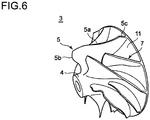
- the impeller 3 includes: a conical hub fixed at one end part of the rotary shaft 2; and a plurality of main blades 5 provided by being protruded from a surface of the hub 4.
- the impeller 3, as illustrated in Fig. 2 may include splitter blades 7 that are formed between the neighboring main blades 5, 5 and are shorter than the main blades 5 in the axial direction. Between the main blades 5 and the splitter blades 7 (when there are no splitter blades 7, between the neighboring main blades 5, 5), flow path 11 through which a gas flows are formed.
- the compressor housing 6, as illustrated in Fig. 1 includes: an inlet flow path 12 that introduces a gas in the axial direction; a diffuser flow path 14 through which a compressed gas is discharged by the impeller 3; and a scroll flow path 16 through which the compressed gas is guided to an outside of the housing.
- the impeller 3 is so formed that a blade tip 5a of each of the main blades 5 follows an inner circumferential shape of a shroud part 18, and is rotatably accommodated in the compressor housing 6. By the impeller 3 being rotated in high speed, a gas flowing in from leading edges 5b flows through the flow path 11 and is accelerated, and flows out from trailing edges 5c to the diffuser flow path 14.
- Fig. 3 is a partially enlarged view illustrating an impeller of a compressor associated with one embodiment, (a) is a meridional plane view viewed from a meridional plane direction, and (b) is a plan view viewed from an axial direction.
- a leading edge 5b of each of the main blades 5, as illustrated in Fig. 3 (a) is extended in a direction orthogonal to a center line CL in a meridional plane view.
- a leading edge 5b of each of the main blades 5, in a plan view is inclined to a rotation direction R side with respect to a first radial direction r outward in the first radial direction in a neighborhood of a center part of the leading edge 5b.
- a planar shape, when a leading edge 5b of each of the main blades 5 is viewed from the axial direction, is described in detail with reference to Fig. 4 .
- Fig. 4 is an explanatory drawing illustrating a planar shape of a leading edge of a main blade.
- a planar shape of the leading edge 5b when a blade length of the leading edge 5b extending to an outside in the first radial direction is denoted as L, is such that a most backward point P1 is formed at a position of 0.2 L outward in the first radial direction.
- a most forward point P2 is formed at a position of 0.8 L outward in the first radial direction.
- the leading edge 5b In a range of 20 to 80% (0.2 to 0.8 L) of the blade length L, the leading edge 5b is inclined at a maximum inclination angle ⁇ 1 to the rotation direction R side with respect to the first radial direction r outward in the first radial direction.
- Fig. 5 is an explanatory drawing for explaining an effect when a leading edge of a main blade is made to be inclined to a rotation direction side with respect to the first radial direction outward in the first radial direction, (a) illustrates a case where the leading edge is parallel to the first radial direction (reference example), and (b) illustrates a case where the leading edge is inclined with respect to the first radial direction (embodiment example).
- An arrow V in the figure represents a gas flow direction, and a length of the arrow V means a magnitude of flow velocity.
- a leading edge 5b of each of the main blades 5 is inclined to the rotation direction R side with respect to the first radial direction outward in the first radial direction in a range of at least 40% to 80% of the blade length L.
- the maximum inclination angle ⁇ 1 in a range of 40% to 80% of the blade length L is in a range of 3 to 20 degrees with respect to the first radial direction, the shock wave generated during high-speed operation of the impeller 3 may be effectively suppressed.
- a connection length between the main blades 5 and the hub 4 may be secured long.
- overhung may be relaxed and stress concentration at a root part of the main blades 5 may be relaxed.
- Fig. 6 is a perspective view illustrating an impeller of a compressor associated with one embodiment.
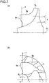
- Fig. 7 is a partially enlarged view illustrating an impeller of a compressor associated with one embodiment, (a) is a meridional plane view viewed from a meridional plane direction, and (b) is a plan view viewed from an axial direction.
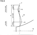
- Fig. 8 is an explanatory drawing illustrating a meridional shape of a leading edge of a main blade.
- the impeller 3 associated with the present embodiment is basically similar to the above-described embodiment, and the same reference numerals are assigned to the same configuration and detailed descriptions may be omitted.
- a planar shape of a leading edge 5b of each of the main blades 5 has a shape similar to the above-described embodiment and, as illustrated in Fig. 7 (a) , the leading edge 5b in a meridional plane view at a neighborhood of the center part is inclined to an upstream side with respect to an axial orthogonal direction p toward the shroud side.
- a most backward point P1 is formed at a position of 0.2 H toward the shroud side.
- the most forward point P2 is formed at a position of 0.8 H toward the shroud side.
- a range of the blade height H of 20 to 80% (0.2 to 0.8 H) is inclined at a maximum inclination angle ⁇ 2 to the upstream side with respect to the axial orthogonal direction p toward the shroud side.
- Fig. 9 is an explanatory drawing for explaining an effect when a leading edge of a main blade is made to be inclined to an upstream side with respect to the axial orthogonal direction toward the shroud side, and is corresponding to Fig. 5 of the above-described embodiment.
- Fig. 9 (a) illustrates a case where the leading edge is parallel to the axial orthogonal direction, and (b) illustrates a case where the leading edge is inclined with respect to the axial orthogonal direction.
- a leading edge 5b of each of the main blades 5 is inclined to the upstream side with respect to the axial orthogonal direction toward the shroud side in a range of at least 40% to 80% of the blade height H.
- the maximum inclination angle ⁇ 2 in a range of 40% to 80% of the blade height H is in a range of 10 to 30 degrees with respect to the first radial direction, the shock wave generated during high-speed operation of the impeller 3 may be effectively suppressed.
- a leading edge 5b of each of the main blades 5, when the impeller 3 is viewed from the meridional plane direction, at an end part of the hub side (for instance, as illustrated in Fig. 8 , in a range of 0.0 to 0.2 H), is inclined to the upstream side with respect to the axial orthogonal direction to the hub side.
- a connection length between the main blades 5 and the hub 4 may be secured long.
- overhung may be relaxed and stress concentration at a root part of the main blades 5 may be relaxed.
- the present invention is not limited to the embodiments, and it goes without saying that various improvements and deformations may be performed within a range not deviating from the gist of the present invention as defined in the appended claims.
- the compressor 1 may be configured as a mixed flow compressor that compresses a gas flowing in the axial direction and discharges the gas in a direction that is diagonal with respect to the axial direction.
- a compressor of at least one embodiment of the present invention is suitably used as a compressor of a turbocharger used for an engine of an automobile or a ship, for instance.
Landscapes
- Engineering & Computer Science (AREA)
- Mechanical Engineering (AREA)
- General Engineering & Computer Science (AREA)
- Structures Of Non-Positive Displacement Pumps (AREA)
Claims (9)
- Compresseur qui est configuré pour comprimer un gaz qui s'écoule depuis une direction axiale et évacuer le gaz dans une direction radiale ou dans une direction qui est diagonale par rapport à la direction axiale, comprenant :un arbre rotatif (2) ;une roue à aubes (3) qui est configurée pour tourner avec l'arbre rotatif (2) ; etun carter de compresseur (6) qui est configuré pour loger de manière rotative la roue à aubes (3), dans lequella roue à aubes (3) inclut un moyeu (4) qui est fixé à l'arbre rotatif (2) et une pluralité d'aubes principales (5) qui sont prévues en saillie à partir du moyeu (4),dans lequel un bord d'attaque (5b) de chacune des aubes principales (5), lorsque la roue à aubes (3) est vue depuis la direction axiale, au niveau d'une position qui est au moins à 50% d'une longueur d'aube s'étendant vers l'extérieur dans une première direction radiale passant par un centre de rotation et le bord d'attaque (5b), est incliné vers un côté sens de rotation par rapport à la première direction radiale vers l'extérieur dans la première direction radiale, etcaractérisé en ce que le bord d'attaque de chacune des aubes principales, dans une plage d'au moins 40 % à 80 % de la longueur d'aube, est incliné vers un côté sens de rotation par rapport à la première direction radiale vers l'extérieur dans la première direction radiale.
- Compresseur selon la revendication 1, dans lequel un angle d'inclinaison maximum dans une plage de 40 % à 80 % de la longueur d'aube est dans une plage de 3 à 20 degrés par rapport à la première direction radiale.
- Compresseur selon la revendication 1 ou 2, dans lequel un bord d'attaque (5b) de chacune des aubes principales (5), lorsque la roue à aubes (3) est vue depuis une direction axiale, au niveau d'une partie d'extrémité à l'intérieur dans la première direction radiale, est incliné vers un côté sens de rotation par rapport à la première direction radiale vers l'intérieur dans la première direction radiale.
- Compresseur selon l'une quelconque des revendications 1 à 3, dans lequel un bord d'attaque de chacune des aubes principales, lorsque la roue à aubes est vue depuis une direction axiale, au niveau d'une partie d'extrémité en dehors dans la première direction radiale, est incliné dans un sens opposé à un sens de rotation par rapport à la première direction radiale vers l'extérieur dans la première direction radiale.
- Compresseur selon l'une quelconque des revendications 1 à 4, dans lequel une forme de plan méridional d'un bord d'attaque de chacune des aubes principales, au niveau d'une position qui est au moins à 50 % d'une hauteur d'aube s'étendant vers un côté carénage du carter de compresseur, est inclinée vers un côté amont par rapport à une direction orthogonale d'axe vers le côté carénage.
- Compresseur selon la revendication 5, dans lequel un bord d'attaque de chacune des aubes principales, dans une plage de 40% à 80 % de la hauteur d'aube, est incliné en continu vers un côté amont par rapport à une direction orthogonale d'axe vers le côté carénage.
- Compresseur selon la revendication 6, dans lequel un angle d'inclinaison maximum dans la plage de 40 % à 80 % de la hauteur d'aube est dans une plage de 10 à 30 degrés par rapport à une direction orthogonale d'axe.
- Compresseur selon l'une quelconque des revendications 5 à 7, dans lequel une forme de plan méridional d'un bord d'attaque de chacune des aubes principales, au niveau d'une partie d'extrémité d'un côté moyeu, est inclinée vers un côté amont par rapport à une direction orthogonale d'axe vers le côté moyeu.
- Compresseur selon l'une quelconque des revendications 5 à 8, dans lequel une forme de plan méridional d'un bord d'attaque de chacune des aubes principales, au niveau d'une partie d'extrémité sur le côté carénage, est inclinée vers un côté aval par rapport à une direction octogonale d'axe vers le côté carénage.
Applications Claiming Priority (2)
| Application Number | Priority Date | Filing Date | Title |
|---|---|---|---|
| JP2012272526A JP5606515B2 (ja) | 2012-12-13 | 2012-12-13 | 圧縮機 |
| PCT/JP2013/074030 WO2014091804A1 (fr) | 2012-12-13 | 2013-09-06 | Compresseur |
Publications (3)
| Publication Number | Publication Date |
|---|---|
| EP2918849A1 EP2918849A1 (fr) | 2015-09-16 |
| EP2918849A4 EP2918849A4 (fr) | 2015-11-25 |
| EP2918849B1 true EP2918849B1 (fr) | 2017-11-01 |
Family
ID=50934103
Family Applications (1)
| Application Number | Title | Priority Date | Filing Date |
|---|---|---|---|
| EP13862737.7A Active EP2918849B1 (fr) | 2012-12-13 | 2013-09-06 | Compresseur |
Country Status (5)
| Country | Link |
|---|---|
| EP (1) | EP2918849B1 (fr) |
| JP (1) | JP5606515B2 (fr) |
| KR (1) | KR101765405B1 (fr) |
| CN (1) | CN104854350B (fr) |
| WO (1) | WO2014091804A1 (fr) |
Cited By (1)
| Publication number | Priority date | Publication date | Assignee | Title |
|---|---|---|---|---|
| DE102022127147A1 (de) | 2022-10-17 | 2024-04-18 | Man Energy Solutions Se | Verdichter und Turbolader |
Families Citing this family (9)
| Publication number | Priority date | Publication date | Assignee | Title |
|---|---|---|---|---|
| JP6745331B2 (ja) * | 2016-03-30 | 2020-08-26 | 三菱重工エンジン&ターボチャージャ株式会社 | 回転機械、ターボチャージャ |
| ITUA20164221A1 (it) * | 2016-06-09 | 2017-12-09 | Fieni Giovanni S R L | Gruppo di ventilazione per atomizzazione ed irrorazione |
| DE102016220133A1 (de) * | 2016-10-14 | 2018-04-19 | Bosch Mahle Turbo Systems Gmbh & Co. Kg | Laufrad für einen Abgasturbolader und Abgasturbolader mit einem solchen Laufrad |
| FR3062431B1 (fr) * | 2017-01-27 | 2021-01-01 | Safran Helicopter Engines | Pale de rouet pour turbomachine, comprenant une ailerette a son sommet et au bord d'attaque |
| JP6842563B2 (ja) * | 2017-10-11 | 2021-03-17 | 三菱重工エンジン&ターボチャージャ株式会社 | 遠心式回転機械のインペラ及び遠心式回転機械 |
| CN107989823B (zh) * | 2017-12-26 | 2023-12-01 | 北京伯肯节能科技股份有限公司 | 叶轮、离心压缩机及燃料电池系统 |
| JP6740271B2 (ja) | 2018-03-05 | 2020-08-12 | 三菱重工業株式会社 | 羽根車及びこの羽根車を備えた遠心圧縮機 |
| CN109404334A (zh) * | 2018-12-27 | 2019-03-01 | 泛仕达机电股份有限公司 | 一种斜流风轮及包括该斜流风轮的低噪声斜流风机 |
| CN112032103B (zh) * | 2019-06-03 | 2022-08-26 | 日本电产株式会社 | 叶轮、送风装置以及吸尘器 |
Family Cites Families (10)
| Publication number | Priority date | Publication date | Assignee | Title |
|---|---|---|---|---|
| JPS6360097U (fr) * | 1986-10-06 | 1988-04-21 | ||
| US6588485B1 (en) * | 2002-05-10 | 2003-07-08 | Borgwarner, Inc. | Hybrid method for manufacturing titanium compressor wheel |
| JP4115180B2 (ja) | 2002-07-11 | 2008-07-09 | 三菱重工業株式会社 | 羽根車および遠心圧縮機 |
| EP1788255A1 (fr) * | 2005-11-16 | 2007-05-23 | Siemens Aktiengesellschaft | Roue de compresseur radial |
| US20080229742A1 (en) * | 2007-03-21 | 2008-09-25 | Philippe Renaud | Extended Leading-Edge Compressor Wheel |
| JP5076999B2 (ja) * | 2008-03-21 | 2012-11-21 | 株式会社Ihi | 遠心圧縮機 |
| US9689263B2 (en) * | 2009-10-27 | 2017-06-27 | General Electric Company | Droplet catcher for centrifugal compressor |
| US8668446B2 (en) * | 2010-08-31 | 2014-03-11 | General Electric Company | Supersonic compressor rotor and method of assembling same |
| GB2486019B (en) * | 2010-12-02 | 2013-02-20 | Dyson Technology Ltd | A fan |
| DE102012004388A1 (de) * | 2012-03-03 | 2013-09-05 | Daimler Ag | Verdichterrad für einen Verdichter, insbesondere einen Radialverdichter |
-
2012
- 2012-12-13 JP JP2012272526A patent/JP5606515B2/ja active Active
-
2013
- 2013-09-06 EP EP13862737.7A patent/EP2918849B1/fr active Active
- 2013-09-06 CN CN201380063648.7A patent/CN104854350B/zh active Active
- 2013-09-06 WO PCT/JP2013/074030 patent/WO2014091804A1/fr active Application Filing
- 2013-09-06 KR KR1020157014099A patent/KR101765405B1/ko active IP Right Grant
Non-Patent Citations (1)
| Title |
|---|
| None * |
Cited By (1)
| Publication number | Priority date | Publication date | Assignee | Title |
|---|---|---|---|---|
| DE102022127147A1 (de) | 2022-10-17 | 2024-04-18 | Man Energy Solutions Se | Verdichter und Turbolader |
Also Published As
| Publication number | Publication date |
|---|---|
| CN104854350A (zh) | 2015-08-19 |
| KR20150079892A (ko) | 2015-07-08 |
| CN104854350B (zh) | 2019-10-01 |
| JP5606515B2 (ja) | 2014-10-15 |
| JP2014118833A (ja) | 2014-06-30 |
| KR101765405B1 (ko) | 2017-08-07 |
| EP2918849A4 (fr) | 2015-11-25 |
| EP2918849A1 (fr) | 2015-09-16 |
| WO2014091804A1 (fr) | 2014-06-19 |
Similar Documents
| Publication | Publication Date | Title |
|---|---|---|
| EP2918849B1 (fr) | Compresseur | |
| EP1741935B1 (fr) | Compresseur centrifuge et proce de de fabrication d'une roue de compresseur | |
| JP6109197B2 (ja) | ラジアルタービン動翼 | |
| KR20180101459A (ko) | 방해받지 않는 출구를 구비하는 엔진 냉각 팬 캐스팅 셔라우드 | |
| US20160305448A1 (en) | Cooling fan module and system | |
| US9745859B2 (en) | Radial-inflow type axial flow turbine and turbocharger | |
| US9816523B2 (en) | Centrifugal compressor | |
| WO2011070636A1 (fr) | Turbine et pale de rotor de turbine | |
| WO2018181343A1 (fr) | Compresseur centrifuge | |
| JP2007224866A (ja) | 遠心圧縮機 | |
| EP3421811A1 (fr) | Roue de compresseur et turbocompresseur | |
| US11125236B2 (en) | Centrifugal compressor | |
| JP6854687B2 (ja) | 多段流体機械 | |
| JP2010001874A (ja) | タービンインペラ、ラジアルタービン及び過給機 | |
| CN110234888B (zh) | 压缩机的涡旋形状以及增压器 | |
| US10844863B2 (en) | Centrifugal rotary machine | |
| CN111356843B (zh) | 多级离心压缩机、壳体以及回流翼片 | |
| JP6019701B2 (ja) | 過給機 | |
| JP5308077B2 (ja) | タービンおよびタービン動翼 | |
| EP3456937B1 (fr) | Turbocompresseur | |
| US11835057B2 (en) | Impeller of centrifugal compressor, centrifugal compressor, and turbocharger | |
| JP7445004B2 (ja) | コンプレッサハウジングおよび遠心圧縮機 | |
| US20230304507A1 (en) | Compressor housing and centrifugal compressor | |
| JP5736650B2 (ja) | 軸流圧縮機及びガスタービンエンジン |
Legal Events
| Date | Code | Title | Description |
|---|---|---|---|
| PUAI | Public reference made under article 153(3) epc to a published international application that has entered the european phase |
Free format text: ORIGINAL CODE: 0009012 |
|
| 17P | Request for examination filed |
Effective date: 20150608 |
|
| AK | Designated contracting states |
Kind code of ref document: A1 Designated state(s): AL AT BE BG CH CY CZ DE DK EE ES FI FR GB GR HR HU IE IS IT LI LT LU LV MC MK MT NL NO PL PT RO RS SE SI SK SM TR |
|
| AX | Request for extension of the european patent |
Extension state: BA ME |
|
| RA4 | Supplementary search report drawn up and despatched (corrected) |
Effective date: 20151027 |
|
| RIC1 | Information provided on ipc code assigned before grant |
Ipc: F04D 29/30 20060101AFI20151021BHEP Ipc: F04D 21/00 20060101ALI20151021BHEP Ipc: F04D 29/28 20060101ALI20151021BHEP |
|
| DAX | Request for extension of the european patent (deleted) | ||
| GRAP | Despatch of communication of intention to grant a patent |
Free format text: ORIGINAL CODE: EPIDOSNIGR1 |
|
| INTG | Intention to grant announced |
Effective date: 20170516 |
|
| GRAS | Grant fee paid |
Free format text: ORIGINAL CODE: EPIDOSNIGR3 |
|
| GRAA | (expected) grant |
Free format text: ORIGINAL CODE: 0009210 |
|
| AK | Designated contracting states |
Kind code of ref document: B1 Designated state(s): AL AT BE BG CH CY CZ DE DK EE ES FI FR GB GR HR HU IE IS IT LI LT LU LV MC MK MT NL NO PL PT RO RS SE SI SK SM TR |
|
| REG | Reference to a national code |
Ref country code: GB Ref legal event code: FG4D |
|
| REG | Reference to a national code |
Ref country code: AT Ref legal event code: REF Ref document number: 942320 Country of ref document: AT Kind code of ref document: T Effective date: 20171115 Ref country code: CH Ref legal event code: EP |
|
| REG | Reference to a national code |
Ref country code: IE Ref legal event code: FG4D |
|
| REG | Reference to a national code |
Ref country code: NL Ref legal event code: FP |
|
| REG | Reference to a national code |
Ref country code: DE Ref legal event code: R096 Ref document number: 602013028940 Country of ref document: DE |
|
| REG | Reference to a national code |
Ref country code: LT Ref legal event code: MG4D |
|
| REG | Reference to a national code |
Ref country code: AT Ref legal event code: MK05 Ref document number: 942320 Country of ref document: AT Kind code of ref document: T Effective date: 20171101 |
|
| PG25 | Lapsed in a contracting state [announced via postgrant information from national office to epo] |
Ref country code: ES Free format text: LAPSE BECAUSE OF FAILURE TO SUBMIT A TRANSLATION OF THE DESCRIPTION OR TO PAY THE FEE WITHIN THE PRESCRIBED TIME-LIMIT Effective date: 20171101 Ref country code: NO Free format text: LAPSE BECAUSE OF FAILURE TO SUBMIT A TRANSLATION OF THE DESCRIPTION OR TO PAY THE FEE WITHIN THE PRESCRIBED TIME-LIMIT Effective date: 20180201 Ref country code: FI Free format text: LAPSE BECAUSE OF FAILURE TO SUBMIT A TRANSLATION OF THE DESCRIPTION OR TO PAY THE FEE WITHIN THE PRESCRIBED TIME-LIMIT Effective date: 20171101 Ref country code: LT Free format text: LAPSE BECAUSE OF FAILURE TO SUBMIT A TRANSLATION OF THE DESCRIPTION OR TO PAY THE FEE WITHIN THE PRESCRIBED TIME-LIMIT Effective date: 20171101 Ref country code: SE Free format text: LAPSE BECAUSE OF FAILURE TO SUBMIT A TRANSLATION OF THE DESCRIPTION OR TO PAY THE FEE WITHIN THE PRESCRIBED TIME-LIMIT Effective date: 20171101 |
|
| PG25 | Lapsed in a contracting state [announced via postgrant information from national office to epo] |
Ref country code: IS Free format text: LAPSE BECAUSE OF FAILURE TO SUBMIT A TRANSLATION OF THE DESCRIPTION OR TO PAY THE FEE WITHIN THE PRESCRIBED TIME-LIMIT Effective date: 20180301 Ref country code: LV Free format text: LAPSE BECAUSE OF FAILURE TO SUBMIT A TRANSLATION OF THE DESCRIPTION OR TO PAY THE FEE WITHIN THE PRESCRIBED TIME-LIMIT Effective date: 20171101 Ref country code: HR Free format text: LAPSE BECAUSE OF FAILURE TO SUBMIT A TRANSLATION OF THE DESCRIPTION OR TO PAY THE FEE WITHIN THE PRESCRIBED TIME-LIMIT Effective date: 20171101 Ref country code: AT Free format text: LAPSE BECAUSE OF FAILURE TO SUBMIT A TRANSLATION OF THE DESCRIPTION OR TO PAY THE FEE WITHIN THE PRESCRIBED TIME-LIMIT Effective date: 20171101 Ref country code: BG Free format text: LAPSE BECAUSE OF FAILURE TO SUBMIT A TRANSLATION OF THE DESCRIPTION OR TO PAY THE FEE WITHIN THE PRESCRIBED TIME-LIMIT Effective date: 20180201 Ref country code: RS Free format text: LAPSE BECAUSE OF FAILURE TO SUBMIT A TRANSLATION OF THE DESCRIPTION OR TO PAY THE FEE WITHIN THE PRESCRIBED TIME-LIMIT Effective date: 20171101 Ref country code: GR Free format text: LAPSE BECAUSE OF FAILURE TO SUBMIT A TRANSLATION OF THE DESCRIPTION OR TO PAY THE FEE WITHIN THE PRESCRIBED TIME-LIMIT Effective date: 20180202 |
|
| PG25 | Lapsed in a contracting state [announced via postgrant information from national office to epo] |
Ref country code: DK Free format text: LAPSE BECAUSE OF FAILURE TO SUBMIT A TRANSLATION OF THE DESCRIPTION OR TO PAY THE FEE WITHIN THE PRESCRIBED TIME-LIMIT Effective date: 20171101 Ref country code: CY Free format text: LAPSE BECAUSE OF FAILURE TO SUBMIT A TRANSLATION OF THE DESCRIPTION OR TO PAY THE FEE WITHIN THE PRESCRIBED TIME-LIMIT Effective date: 20171101 Ref country code: EE Free format text: LAPSE BECAUSE OF FAILURE TO SUBMIT A TRANSLATION OF THE DESCRIPTION OR TO PAY THE FEE WITHIN THE PRESCRIBED TIME-LIMIT Effective date: 20171101 Ref country code: SK Free format text: LAPSE BECAUSE OF FAILURE TO SUBMIT A TRANSLATION OF THE DESCRIPTION OR TO PAY THE FEE WITHIN THE PRESCRIBED TIME-LIMIT Effective date: 20171101 Ref country code: CZ Free format text: LAPSE BECAUSE OF FAILURE TO SUBMIT A TRANSLATION OF THE DESCRIPTION OR TO PAY THE FEE WITHIN THE PRESCRIBED TIME-LIMIT Effective date: 20171101 |
|
| REG | Reference to a national code |
Ref country code: DE Ref legal event code: R097 Ref document number: 602013028940 Country of ref document: DE |
|
| PG25 | Lapsed in a contracting state [announced via postgrant information from national office to epo] |
Ref country code: SM Free format text: LAPSE BECAUSE OF FAILURE TO SUBMIT A TRANSLATION OF THE DESCRIPTION OR TO PAY THE FEE WITHIN THE PRESCRIBED TIME-LIMIT Effective date: 20171101 Ref country code: IT Free format text: LAPSE BECAUSE OF FAILURE TO SUBMIT A TRANSLATION OF THE DESCRIPTION OR TO PAY THE FEE WITHIN THE PRESCRIBED TIME-LIMIT Effective date: 20171101 Ref country code: PL Free format text: LAPSE BECAUSE OF FAILURE TO SUBMIT A TRANSLATION OF THE DESCRIPTION OR TO PAY THE FEE WITHIN THE PRESCRIBED TIME-LIMIT Effective date: 20171101 Ref country code: RO Free format text: LAPSE BECAUSE OF FAILURE TO SUBMIT A TRANSLATION OF THE DESCRIPTION OR TO PAY THE FEE WITHIN THE PRESCRIBED TIME-LIMIT Effective date: 20171101 |
|
| PLBE | No opposition filed within time limit |
Free format text: ORIGINAL CODE: 0009261 |
|
| STAA | Information on the status of an ep patent application or granted ep patent |
Free format text: STATUS: NO OPPOSITION FILED WITHIN TIME LIMIT |
|
| REG | Reference to a national code |
Ref country code: FR Ref legal event code: PLFP Year of fee payment: 6 |
|
| 26N | No opposition filed |
Effective date: 20180802 |
|
| PG25 | Lapsed in a contracting state [announced via postgrant information from national office to epo] |
Ref country code: SI Free format text: LAPSE BECAUSE OF FAILURE TO SUBMIT A TRANSLATION OF THE DESCRIPTION OR TO PAY THE FEE WITHIN THE PRESCRIBED TIME-LIMIT Effective date: 20171101 |
|
| PG25 | Lapsed in a contracting state [announced via postgrant information from national office to epo] |
Ref country code: MC Free format text: LAPSE BECAUSE OF FAILURE TO SUBMIT A TRANSLATION OF THE DESCRIPTION OR TO PAY THE FEE WITHIN THE PRESCRIBED TIME-LIMIT Effective date: 20171101 |
|
| REG | Reference to a national code |
Ref country code: CH Ref legal event code: PL |
|
| REG | Reference to a national code |
Ref country code: BE Ref legal event code: MM Effective date: 20180930 |
|
| REG | Reference to a national code |
Ref country code: IE Ref legal event code: MM4A |
|
| PG25 | Lapsed in a contracting state [announced via postgrant information from national office to epo] |
Ref country code: LU Free format text: LAPSE BECAUSE OF NON-PAYMENT OF DUE FEES Effective date: 20180906 |
|
| PG25 | Lapsed in a contracting state [announced via postgrant information from national office to epo] |
Ref country code: IE Free format text: LAPSE BECAUSE OF NON-PAYMENT OF DUE FEES Effective date: 20180906 |
|
| PG25 | Lapsed in a contracting state [announced via postgrant information from national office to epo] |
Ref country code: BE Free format text: LAPSE BECAUSE OF NON-PAYMENT OF DUE FEES Effective date: 20180930 Ref country code: LI Free format text: LAPSE BECAUSE OF NON-PAYMENT OF DUE FEES Effective date: 20180930 Ref country code: CH Free format text: LAPSE BECAUSE OF NON-PAYMENT OF DUE FEES Effective date: 20180930 |
|
| PG25 | Lapsed in a contracting state [announced via postgrant information from national office to epo] |
Ref country code: MT Free format text: LAPSE BECAUSE OF NON-PAYMENT OF DUE FEES Effective date: 20180906 |
|
| PG25 | Lapsed in a contracting state [announced via postgrant information from national office to epo] |
Ref country code: TR Free format text: LAPSE BECAUSE OF FAILURE TO SUBMIT A TRANSLATION OF THE DESCRIPTION OR TO PAY THE FEE WITHIN THE PRESCRIBED TIME-LIMIT Effective date: 20171101 |
|
| PG25 | Lapsed in a contracting state [announced via postgrant information from national office to epo] |
Ref country code: PT Free format text: LAPSE BECAUSE OF FAILURE TO SUBMIT A TRANSLATION OF THE DESCRIPTION OR TO PAY THE FEE WITHIN THE PRESCRIBED TIME-LIMIT Effective date: 20171101 |
|
| PG25 | Lapsed in a contracting state [announced via postgrant information from national office to epo] |
Ref country code: HU Free format text: LAPSE BECAUSE OF FAILURE TO SUBMIT A TRANSLATION OF THE DESCRIPTION OR TO PAY THE FEE WITHIN THE PRESCRIBED TIME-LIMIT; INVALID AB INITIO Effective date: 20130906 Ref country code: MK Free format text: LAPSE BECAUSE OF NON-PAYMENT OF DUE FEES Effective date: 20171101 |
|
| PG25 | Lapsed in a contracting state [announced via postgrant information from national office to epo] |
Ref country code: AL Free format text: LAPSE BECAUSE OF FAILURE TO SUBMIT A TRANSLATION OF THE DESCRIPTION OR TO PAY THE FEE WITHIN THE PRESCRIBED TIME-LIMIT Effective date: 20171101 |
|
| PGFP | Annual fee paid to national office [announced via postgrant information from national office to epo] |
Ref country code: NL Payment date: 20230816 Year of fee payment: 11 |
|
| PGFP | Annual fee paid to national office [announced via postgrant information from national office to epo] |
Ref country code: GB Payment date: 20230727 Year of fee payment: 11 |
|
| PGFP | Annual fee paid to national office [announced via postgrant information from national office to epo] |
Ref country code: FR Payment date: 20230808 Year of fee payment: 11 Ref country code: DE Payment date: 20230802 Year of fee payment: 11 |