WO2018181343A1 - Compresseur centrifuge - Google Patents
Compresseur centrifuge Download PDFInfo
- Publication number
- WO2018181343A1 WO2018181343A1 PCT/JP2018/012477 JP2018012477W WO2018181343A1 WO 2018181343 A1 WO2018181343 A1 WO 2018181343A1 JP 2018012477 W JP2018012477 W JP 2018012477W WO 2018181343 A1 WO2018181343 A1 WO 2018181343A1
- Authority
- WO
- WIPO (PCT)
- Prior art keywords
- return
- flow path
- return vane
- centrifugal compressor
- thickness
- Prior art date
Links
Images

Classifications
-
- F—MECHANICAL ENGINEERING; LIGHTING; HEATING; WEAPONS; BLASTING
- F04—POSITIVE - DISPLACEMENT MACHINES FOR LIQUIDS; PUMPS FOR LIQUIDS OR ELASTIC FLUIDS
- F04D—NON-POSITIVE-DISPLACEMENT PUMPS
- F04D29/00—Details, component parts, or accessories
- F04D29/40—Casings; Connections of working fluid
- F04D29/42—Casings; Connections of working fluid for radial or helico-centrifugal pumps
- F04D29/44—Fluid-guiding means, e.g. diffusers
- F04D29/441—Fluid-guiding means, e.g. diffusers especially adapted for elastic fluid pumps
- F04D29/444—Bladed diffusers
-
- F—MECHANICAL ENGINEERING; LIGHTING; HEATING; WEAPONS; BLASTING
- F04—POSITIVE - DISPLACEMENT MACHINES FOR LIQUIDS; PUMPS FOR LIQUIDS OR ELASTIC FLUIDS
- F04D—NON-POSITIVE-DISPLACEMENT PUMPS
- F04D29/00—Details, component parts, or accessories
- F04D29/40—Casings; Connections of working fluid
- F04D29/42—Casings; Connections of working fluid for radial or helico-centrifugal pumps
- F04D29/44—Fluid-guiding means, e.g. diffusers
-
- F—MECHANICAL ENGINEERING; LIGHTING; HEATING; WEAPONS; BLASTING
- F04—POSITIVE - DISPLACEMENT MACHINES FOR LIQUIDS; PUMPS FOR LIQUIDS OR ELASTIC FLUIDS
- F04D—NON-POSITIVE-DISPLACEMENT PUMPS
- F04D17/00—Radial-flow pumps, e.g. centrifugal pumps; Helico-centrifugal pumps
- F04D17/08—Centrifugal pumps
- F04D17/10—Centrifugal pumps for compressing or evacuating
- F04D17/12—Multi-stage pumps
- F04D17/122—Multi-stage pumps the individual rotor discs being, one for each stage, on a common shaft and axially spaced, e.g. conventional centrifugal multi- stage compressors
-
- F—MECHANICAL ENGINEERING; LIGHTING; HEATING; WEAPONS; BLASTING
- F04—POSITIVE - DISPLACEMENT MACHINES FOR LIQUIDS; PUMPS FOR LIQUIDS OR ELASTIC FLUIDS
- F04D—NON-POSITIVE-DISPLACEMENT PUMPS
- F04D29/00—Details, component parts, or accessories
- F04D29/40—Casings; Connections of working fluid
- F04D29/42—Casings; Connections of working fluid for radial or helico-centrifugal pumps
- F04D29/44—Fluid-guiding means, e.g. diffusers
- F04D29/441—Fluid-guiding means, e.g. diffusers especially adapted for elastic fluid pumps
Definitions
- the present invention relates to a centrifugal compressor.
- This application claims priority based on Japanese Patent Application No. 2017-071308 filed in Japan on March 31, 2017, the contents of which are incorporated herein by reference.
- a multistage centrifugal compressor having an impeller in which a plurality of blades are attached to a disk fixed to a rotating shaft is known.
- This multistage centrifugal compressor applies pressure energy and velocity energy to the working fluid G by rotating the impeller.
- a pair of impellers adjacent to each other in the axial direction of the rotation shaft are connected by a return flow path.
- the return flow path is provided with a return vane for removing the swirling component from the working fluid.
- the centrifugal compressor according to the first aspect of the present invention includes a rotating shaft that rotates about an axis, and a plurality of stages arranged on the rotating shaft in the axial direction, and a working fluid that flows in from an inlet on one side in the axial direction.
- a return vane provided with a plurality of circumferentially spaced return vanes in the return flow path, the return vane including a leading edge.
- the thickness on the hub side on the one axial side in the region is larger than the thickness on the shroud side on the other axial side.
- the centrifugal compressor having such a configuration the circumferential interval between the return vanes adjacent to each other in the circumferential direction is smaller on the hub side than on the shroud side. Therefore, the pressure gradient between the return vanes is more remarkable on the hub side with a smaller interval than on the shroud side with a larger interval.
- the secondary flow particularly on the hub side becomes larger than the secondary flow on the shroud side.
- a large amount of high-energy fluid on the pressure surface of the return vane is supplied to the hub side of the negative pressure surface of the return vane adjacent to the return vane.
- the separation region on the suction surface of the return vane is due to the effect that the flow path is curved toward the other side in the axial direction on the outlet side of the return vane. It has the property of approaching to the side. Since the separation region hinders the mainstream flow and reduces the efficiency of the centrifugal compressor, it is preferable to reduce the area occupied by the separation region on the negative pressure surface of the return vane as much as possible.
- the high energy fluid on the hub side in the pressure surface of the return vane is supplied to the hub side in the suction surface of the return vane adjacent to the return vane. Therefore, the high-energy fluid pushes the separation region to the shroud side at the suction surface of the return vane. For this reason, the peeling region that has originally approached the shroud side can be brought closer to the shroud side. As a result, it is possible to reduce the area occupied by the separation region S on the suction surface of the return vane. Therefore, inhibition of the mainstream flow is suppressed, and a decrease in efficiency of the centrifugal compressor can be suppressed. Note that the high energy fluid supplied from the pressure surface of the return vane to the suction surface has little interference with the separated fluid on the suction surface, so that the energy is not greatly impaired.
- the return vane monotonously decreases in the region including the leading edge from the hub side toward the shroud side.
- the region including the leading edge is preferably a region of 10% to 30% from the leading edge toward the trailing edge in the radial dimension of the return vane.
- the pressure difference between the pressure surface and the suction surface of the return vane is most noticeable on the leading edge side that turns the flow of the fluid, and is small on the trailing edge side. Therefore, a sufficient effect can be obtained by setting the region where the thickness of the return vane on the hub side is larger than the thickness on the shroud side only in the above range on the front edge side. Further, when the thickness gradient of the return vane on the hub side and the shroud side is formed by cutting or the like, it is only necessary to add processing to the above range, so that an increase in manufacturing cost can be suppressed.
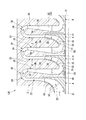
- the centrifugal compressor 100 is provided on a rotating shaft 1 that rotates around an axis O, a casing 3 that forms a flow path 2 by covering the periphery of the rotating shaft 1, and the rotating shaft 1.
- a plurality of impellers 4 and a return vane 50 provided in the casing 3 are provided.
- the casing 3 has a cylindrical shape extending along the axis O.
- the rotating shaft 1 extends so as to penetrate the inside of the casing 3 along the axis O.
- Journal bearings 5 and thrust bearings 6 are provided at both ends of the casing 3 in the direction of the axis O, respectively.
- the rotary shaft 1 is supported by the journal bearing 5 and the thrust bearing 6 so as to be rotatable around the axis O.
- an air inlet 7 for taking in air as the working fluid G from the outside is provided on one side of the casing 3 in the direction of the axis O. Furthermore, an exhaust port 8 through which the working fluid G compressed inside the casing 3 is exhausted is provided on the other side of the casing 3 in the axis O direction.
- an internal space is formed in which the intake port 7 and the exhaust port 8 communicate with each other and the diameter is repeatedly reduced and increased.
- the internal space accommodates a plurality of impellers 4 and forms part of the flow path 2 described above.
- the side on the flow path 2 where the intake port 7 is located is called the upstream side
- the side where the exhaust port 8 is located is called the downstream side.
- the rotary shaft 1 is provided with a plurality (six) of impellers 4 at intervals on the outer peripheral surface in the direction of the axis O.
- each impeller 4 includes a disk 41 having a substantially circular cross section when viewed from the direction of the axis O, a plurality of blades 42 provided on the upstream surface of the disk 41, and the plurality of blades And a cover 43 that covers 42 from the upstream side.
- the disk 41 is formed so that the radial dimension gradually increases from one side of the axis O direction to the other side when viewed from the direction intersecting the axis O, so that the disk 41 has a generally conical shape. Yes.
- a plurality of blades 42 are radially arranged on the conical surface facing the upstream side out of both surfaces in the direction of the axis O of the disk 41 and radially outward with the axis O as the center. More specifically, these blades are formed by thin plates that are erected from the upstream surface of the disk 41 toward the upstream side. The plurality of blades 42 are curved so as to be directed from one side to the other side in the circumferential direction when viewed from the direction of the axis O.
- a cover 43 is provided on the upstream edge of the blade 42.
- the plurality of blades 42 are sandwiched by the cover 43 and the disk 41 from the direction of the axis O.
- a space is formed between the cover 43, the disk 41, and a pair of blades 42 adjacent to each other. This space forms part of the flow path 2 (compression flow path 22) described later.
- the flow path 2 is a space that communicates the impeller 4 configured as described above and the internal space of the casing 3.
- description will be made assuming that one flow path 2 is formed for each impeller 4 (for each compression stage). That is, in the centrifugal compressor 100, five flow paths 2 continuous from the upstream side toward the downstream side are formed corresponding to the five impellers 4 excluding the last stage impeller 4.
- Each flow path 2 has a suction flow path 21, a compression flow path 22, a diffuser flow path 23, and a return flow path 30.
- FIG. 2 mainly shows the first to third stage impellers 4 of the flow path 2 and the impeller 4.
- the suction flow path 21 is directly connected to the intake port 7. External air is taken into each flow path on the flow path 2 as the working fluid G by the suction flow path 21. More specifically, the suction passage 21 is gradually curved from the axis O direction toward the radial outer side as it goes from the upstream side to the downstream side.
- the suction flow path 21 in the impeller 4 after the second stage communicates with the downstream end of the guide flow path 25 (described later) in the flow path 2 in the previous stage (first stage). That is, the flow direction of the working fluid G that has passed through the guide flow path 25 is changed so as to face the downstream side along the axis O in the same manner as described above.
- the compression flow path 22 is a flow path surrounded by the upstream surface of the disk 41, the downstream surface of the cover 43, and a pair of blades 42 adjacent in the circumferential direction. More specifically, the cross-sectional area of the compression flow path 22 gradually decreases from the radially inner side toward the outer side. As a result, the working fluid G flowing through the compression flow path 22 while the impeller 4 is rotating is gradually compressed to become the high-pressure working fluid G.
- the diffuser flow path 23 is a flow path extending from the inside in the radial direction of the axis O toward the outside.
- the radially inner end of the diffuser channel 23 communicates with the radially outer end of the compression channel 22.
- the return flow path 30 is a flow path for turning the working fluid G directed radially outward toward the radially inner side and flowing into the impeller 4 at the next stage.
- the return channel 30 is formed by a return bend portion 24 and a guide channel 25.
- the return bend section 24 reverses the flow direction of the working fluid G flowing from the inside in the radial direction to the outside through the diffuser flow path 23 toward the inside in the radial direction.
- One end side (upstream side) of the return bend portion 24 is communicated with the diffuser flow path 23, and the other end side (downstream side) is communicated with the guide flow path 25.
- a portion located on the outermost side in the radial direction is a top portion. In the vicinity of the top portion, the inner wall surface of the return bend portion 24 forms a three-dimensional curved surface so that the flow of the working fluid G is not hindered.
- the guide channel 25 extends radially inward from the downstream end of the return bend portion 24.
- the radially outer end of the guide channel 25 communicates with the return bend 24 described above.
- the radially inner end of the guide channel 25 is in communication with the suction channel 21 in the downstream channel 2 as described above.
- the wall surface on one side in the axis O direction is the hub side wall surface 3 a.
- the wall surface on the other side in the axis O direction is the shroud side wall surface 3b.
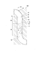
- a plurality of return vanes 50 are provided in the guide channel 25 in the return channel 30.
- the plurality of return vanes 50 are arranged in a radial pattern around the axis O in the guide channel 25.
- the return vanes 50 are arranged around the axis O at intervals in the circumferential direction. Both ends of the return vane 50 in the direction of the axis O are in contact with the casing 3 that forms the guide channel 25. That is, one side (hub side) of the return vane 50 in the axis O direction is in contact with the hub side wall surface 3a over the entire radial direction. The other side (shroud side) of the return vane 50 in the axis O direction is in contact with the shroud side wall surface 3b over the entire radial direction.
- the return vane 50 When viewed from the direction of the axis O, the return vane 50 has a blade shape with the radially outer end as a leading edge 51 and the radially inner end as a trailing edge 52.
- the return vane 50 extends toward the front side in the rotational direction R of the rotary shaft 1 as it goes from the front edge 51 to the rear edge 52.
- the return vane 50 is curved so as to be convex toward the front side in the rotational direction R.
- the surface of the return vane 50 facing the front side in the rotation direction R is a negative pressure surface 53, and the surface facing the rotation direction R rear side is a pressure surface 54.
- the return vane 50 includes a front edge side region 60 including a front edge 51 and a rear edge side region 70 connected to a radially inner side of the front edge side region 60 and including a rear edge 52. It is divided into two areas.
- the leading edge side region 60 is a region of 10 to 30% of the radial dimension of the return vane 50 from the leading edge 51 toward the trailing edge 52, and the trailing edge side region 70 is from the trailing edge 52 toward the leading edge 51. The rest of the area.
- the boundary between the front edge side region 60 and the rear edge side region 70 is parallel to the axis O.
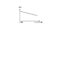
- the thickness at each radial position of the front edge side region 60 of each return vane 50 is such that the end portion on the hub side of the return vane 50 is shroud. Larger than the side edge.
- the thickness of the return vane 50 in the front edge side region 60 monotonously decreases from the hub side toward the shroud side.
- the thickness of the return vane 50 in the leading edge side region 60 decreases linearly with a certain inclination from the hub side toward the shroud side.
- the thickness of the return vane 50 is different between the hub side and the shroud side only in the front edge side region 60 of the return vane 50, and in the rear edge side region 70, the thickness is constant from the hub side to the shroud side.
- the leading edge side region 60 and the trailing edge side region 70 are connected to the pressure surface 54 and the negative pressure surface 53 smoothly and continuously, the leading edge side region 60 is at the boundary with the trailing edge side region 70 as described above. And the shroud side are formed so that there is no difference in thickness.
- the leading edge 51 of the return vane 50 is curved in a convex shape outward in the radial direction in a cross-sectional view orthogonal to the axis O. It has a shape.
- a pressure surface 54 and a negative pressure surface 53 are formed so as to be continuous with the curved shape.
- the thickness of the return vane 50 in the front edge side region 60 is defined as a portion of the front edge 51 excluding the curved shape, that is, a dimension between the pressure surface 54 and the suction surface 53.
- the thickness of the return vane 50 at the trailing edge side region 70 is similarly defined as a dimension between the pressure surface 54 and the negative pressure surface 53.
- the high-pressure working fluid G pumped from the compression flow path 22 then passes through the diffuser flow path 23, the return bend portion 24, and the guide flow path 25 in this order.
- the same compression is applied to the impeller 4 and the flow path 2 after the second stage.
- the working fluid G is in a desired pressure state and is supplied from an exhaust port 8 to an external device (not shown).
- each return vane 50 in the front edge side region 60 is larger on the hub side than on the shroud side. Therefore, as shown in FIG. 4, the circumferential interval between the return vanes 50 adjacent to each other in the circumferential direction is smaller on the hub side than on the shroud side. Therefore, the pressure gradient in the circumferential direction between the return vanes 50 is larger on the hub side with a smaller interval than on the shroud side with a larger interval.
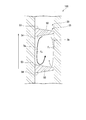
- the separation region S on the suction surface 53 of the return vane 50 is such that the suction flow path of the next stage (rear stage side) impeller on the outlet side of the return vane 50 is curved to the other side in the axis O direction.
- the return vane 50 approaches the shroud side as it goes radially inward. Since the separation region S hinders the mainstream flow, the efficiency of the centrifugal compressor 100 is reduced. Therefore, it is preferable to reduce the area occupied by the separation region S on the negative pressure surface 53 of the return vane 50 as much as possible.
- the high energy fluid E on the hub side in the pressure surface 54 of the return vane 50 is supplied to the hub side in the negative pressure surface 53 of the return vane 50 adjacent to the return vane 50. Therefore, as shown in FIG. 3, the high energy fluid E pushes the separation region S toward the shroud side at the suction surface 53 of the return vane 50. Therefore, the peeling area S originally approaching the shroud side can be brought closer to the shroud side. As a result, the occupation area of the separation region S on the suction surface 53 of the return vane 50 can be reduced. Thereby, the efficiency fall of the centrifugal compressor 100 can be suppressed.
- the high energy fluid E supplied from the pressure surface 54 of the return vane 50 to the suction surface 53 has little interference with the separated fluid on the suction surface 53. Therefore, the energy of the high energy fluid E is not greatly impaired.
- the thickness of the return vane 50 at the front edge side region 60 monotonously decreases from the hub side toward the shroud side. Therefore, the pressure gradient between the return vanes 50 adjacent to each other gradually increases toward the hub side. Therefore, the high-energy fluid E on the hub side of the pressure surface 54 can be appropriately transported to the hub side of the negative pressure surface 53.
- the pressure difference between the pressure surface 54 and the negative pressure surface 53 of the return vane 50 is most noticeable on the front edge 51 side for turning the fluid flow, and is small on the rear edge 52 side. Therefore, a sufficient effect can be obtained by setting the region where the thickness of the hub of the return vane 50 on the hub side is larger than the thickness of the shroud side only in the above range on the front edge 51 side. Further, when the thickness gradient between the hub side and the shroud side of the return vane 50 is formed by cutting or the like, it is only necessary to add processing to the above range, so that an increase in manufacturing cost can be suppressed.
- the hub side thickness is larger than the shroud side thickness only in the leading edge side region 60 which is a region of 10% to 30% from the leading edge 51 to the trailing edge 52 in the radial dimension of the return vane 50. Is also big. Therefore, an increase in manufacturing cost can be suppressed while reducing the separation region S on the negative pressure surface 53 of the return vane 50.
- the throat area as a flow path between the return vanes 50 is reduced.
- the thickness on the shroud side may be reduced by the amount corresponding to the increase in the thickness on the hub side. Thereby, the throat area can be appropriately secured.
- the thickness decreases with a constant slope from the hub side toward the shroud side, but the present invention is not limited to this.
- the thickness may be monotonously decreased from the hub side toward the shroud side.
- the configuration in which the return vane 50 is formed only in the guide flow path of the return flow path 30 has been described. However, even if the front edge 51 of the return vane 50 is located in the return bend portion 24. Good.
- the front edge 51 of the return vane 50 may be located not only at the boundary between the return bend portion 24 and the guide channel, but also at the radially inner side or the outer side from the boundary.
- the thickness of the hub side of the return vane 50 is larger than the thickness of the shroud side only in the leading edge side region 60, but the thickness of the hub side in the entire radial direction of the return vane 50 is the shroud side thickness. It may be larger than the thickness.
- the present invention is applicable to a centrifugal compressor.
Landscapes
- Engineering & Computer Science (AREA)
- Mechanical Engineering (AREA)
- General Engineering & Computer Science (AREA)
- Structures Of Non-Positive Displacement Pumps (AREA)
Abstract
La présente invention concerne un compresseur centrifuge qui est pourvu : d'une pluralité d'étages de roues d'impulseur (4) disposées dans la direction de la ligne axiale (O) et réalisant l'alimentation forcée d'un fluide de travail introduit à partir d'une entrée à un côté dans la direction de la ligne axiale (O) vers l'extérieur dans la direction radiale ; d'un carter (3) entourant les roues d'impulseur (4) et comportant des passages d'écoulement de retour (30) guidant le fluide de travail évacué de la roue d'impulseur côté étage avant (4) parmi les roues d'impulseur voisines vers l'intérieur dans la direction radiale pour introduire le fluide de travail dans la roue d'impulseur côté étage arrière ; et d'une pluralité d'aubes de retour (50) disposées dans les passages d'écoulement de retour (30) à des intervalles dans la direction circonférentielle, dans les aubes de retour (50), une épaisseur côté moyeu dans une région côté bord d'attaque étant plus grande qu'une épaisseur côté carénage.
Priority Applications (1)
| Application Number | Priority Date | Filing Date | Title |
|---|---|---|---|
| US16/491,359 US11073163B2 (en) | 2017-03-31 | 2018-03-27 | Centrifugal compressor |
Applications Claiming Priority (2)
| Application Number | Priority Date | Filing Date | Title |
|---|---|---|---|
| JP2017071308A JP2018173020A (ja) | 2017-03-31 | 2017-03-31 | 遠心圧縮機 |
| JP2017-071308 | 2017-03-31 |
Publications (1)
| Publication Number | Publication Date |
|---|---|
| WO2018181343A1 true WO2018181343A1 (fr) | 2018-10-04 |
Family
ID=63677284
Family Applications (1)
| Application Number | Title | Priority Date | Filing Date |
|---|---|---|---|
| PCT/JP2018/012477 WO2018181343A1 (fr) | 2017-03-31 | 2018-03-27 | Compresseur centrifuge |
Country Status (3)
| Country | Link |
|---|---|
| US (1) | US11073163B2 (fr) |
| JP (1) | JP2018173020A (fr) |
| WO (1) | WO2018181343A1 (fr) |
Cited By (2)
| Publication number | Priority date | Publication date | Assignee | Title |
|---|---|---|---|---|
| CN113074139A (zh) * | 2020-01-06 | 2021-07-06 | 广东威灵电机制造有限公司 | 扩压装置、风机及吸尘器 |
| CN113074138A (zh) * | 2020-01-06 | 2021-07-06 | 广东威灵电机制造有限公司 | 扩压装置、风机及吸尘器 |
Families Citing this family (4)
| Publication number | Priority date | Publication date | Assignee | Title |
|---|---|---|---|---|
| WO2019193683A1 (fr) * | 2018-04-04 | 2019-10-10 | 三菱重工エンジン&ターボチャージャ株式会社 | Compresseur centrifuge et turbocompresseur de suralimentation comprenant ledit compresseur centrifuge |
| JP2021011828A (ja) * | 2019-07-04 | 2021-02-04 | 三菱重工業株式会社 | 多段遠心圧縮機 |
| JP7432474B2 (ja) | 2020-09-02 | 2024-02-16 | 株式会社荏原製作所 | 遠心圧縮機 |
| JP2023167166A (ja) * | 2022-05-11 | 2023-11-24 | 三菱重工業株式会社 | 多段遠心圧縮機及び多段遠心圧縮機の調整方法 |
Citations (4)
| Publication number | Priority date | Publication date | Assignee | Title |
|---|---|---|---|---|
| JPS60111097A (ja) * | 1983-11-21 | 1985-06-17 | Ebara Corp | 遠心圧縮機のリタ−ンチヤンネル |
| US20070140889A1 (en) * | 2005-12-15 | 2007-06-21 | Jiing Fu Chen | Flow passage structure for refrigerant compressor |
| JP2010216456A (ja) * | 2009-03-19 | 2010-09-30 | Hitachi Plant Technologies Ltd | 多段遠心圧縮機及び多段遠心圧縮機の改造方法 |
| JP2012102712A (ja) * | 2010-11-15 | 2012-05-31 | Mitsubishi Heavy Ind Ltd | ターボ型圧縮機械 |
Family Cites Families (5)
| Publication number | Priority date | Publication date | Assignee | Title |
|---|---|---|---|---|
| DE102009019061A1 (de) * | 2009-04-27 | 2010-10-28 | Man Diesel & Turbo Se | Mehrstufiger Radialverdichter |
| JP6097487B2 (ja) | 2012-03-16 | 2017-03-15 | 三菱重工業株式会社 | 遠心ポンプ |
| CN104781562B (zh) * | 2013-01-28 | 2018-03-09 | 三菱重工业株式会社 | 离心旋转机械 |
| EP3364039A1 (fr) * | 2017-02-21 | 2018-08-22 | Siemens Aktiengesellschaft | Étage de retour |
| EP3376041A1 (fr) * | 2017-03-15 | 2018-09-19 | Siemens Aktiengesellschaft | Étage de recirculation et turbomachine à énergie fluidique radiale |
-
2017
- 2017-03-31 JP JP2017071308A patent/JP2018173020A/ja not_active Ceased
-
2018
- 2018-03-27 WO PCT/JP2018/012477 patent/WO2018181343A1/fr active Application Filing
- 2018-03-27 US US16/491,359 patent/US11073163B2/en active Active
Patent Citations (4)
| Publication number | Priority date | Publication date | Assignee | Title |
|---|---|---|---|---|
| JPS60111097A (ja) * | 1983-11-21 | 1985-06-17 | Ebara Corp | 遠心圧縮機のリタ−ンチヤンネル |
| US20070140889A1 (en) * | 2005-12-15 | 2007-06-21 | Jiing Fu Chen | Flow passage structure for refrigerant compressor |
| JP2010216456A (ja) * | 2009-03-19 | 2010-09-30 | Hitachi Plant Technologies Ltd | 多段遠心圧縮機及び多段遠心圧縮機の改造方法 |
| JP2012102712A (ja) * | 2010-11-15 | 2012-05-31 | Mitsubishi Heavy Ind Ltd | ターボ型圧縮機械 |
Cited By (4)
| Publication number | Priority date | Publication date | Assignee | Title |
|---|---|---|---|---|
| CN113074139A (zh) * | 2020-01-06 | 2021-07-06 | 广东威灵电机制造有限公司 | 扩压装置、风机及吸尘器 |
| CN113074138A (zh) * | 2020-01-06 | 2021-07-06 | 广东威灵电机制造有限公司 | 扩压装置、风机及吸尘器 |
| CN113074138B (zh) * | 2020-01-06 | 2022-05-17 | 广东威灵电机制造有限公司 | 扩压装置、风机及吸尘器 |
| CN113074139B (zh) * | 2020-01-06 | 2023-05-12 | 广东威灵电机制造有限公司 | 扩压装置、风机及吸尘器 |
Also Published As
| Publication number | Publication date |
|---|---|
| JP2018173020A (ja) | 2018-11-08 |
| US11073163B2 (en) | 2021-07-27 |
| US20200056624A1 (en) | 2020-02-20 |
Similar Documents
| Publication | Publication Date | Title |
|---|---|---|
| WO2018181343A1 (fr) | Compresseur centrifuge | |
| JP6323454B2 (ja) | 遠心圧縮機及び過給機 | |
| US9163642B2 (en) | Impeller and rotary machine | |
| WO2014115417A1 (fr) | Machine à rotation centrifuge | |
| JP2018135768A (ja) | 遠心圧縮機 | |
| WO2013128539A1 (fr) | Machine rotative | |
| US20220372992A1 (en) | Rotating machinery | |
| JP2007224866A (ja) | 遠心圧縮機 | |
| JP2024086911A (ja) | インペラ、及び遠心圧縮機 | |
| US11125236B2 (en) | Centrifugal compressor | |
| EP3096022A1 (fr) | Roue à aubes et machine rotative la comportant | |
| WO2015019909A1 (fr) | Compresseur centrifuge et surcompresseur | |
| US10975883B2 (en) | Centrifugal rotary machine | |
| JP2014152637A (ja) | 遠心圧縮機 | |
| US11187242B2 (en) | Multi-stage centrifugal compressor | |
| JP5182519B2 (ja) | 遠心圧縮機 | |
| CN111356843B (zh) | 多级离心压缩机、壳体以及回流翼片 | |
| JP6768172B1 (ja) | 遠心圧縮機 | |
| CN110177951B (zh) | 叶轮及离心压缩机 | |
| JP2017057779A (ja) | ターボチャージャ | |
| JP2023023914A (ja) | 遠心圧縮機 |
Legal Events
| Date | Code | Title | Description |
|---|---|---|---|
| 121 | Ep: the epo has been informed by wipo that ep was designated in this application |
Ref document number: 18775736 Country of ref document: EP Kind code of ref document: A1 |
|
| NENP | Non-entry into the national phase |
Ref country code: DE |
|
| 122 | Ep: pct application non-entry in european phase |
Ref document number: 18775736 Country of ref document: EP Kind code of ref document: A1 |