EP2918391A1 - Dispositif et procédé de transformation d'ébauches en matière synthétique en récipients en plastique à l'aide de dispositif de changement automatique pour des parties de garnitures - Google Patents
Dispositif et procédé de transformation d'ébauches en matière synthétique en récipients en plastique à l'aide de dispositif de changement automatique pour des parties de garnitures Download PDFInfo
- Publication number
- EP2918391A1 EP2918391A1 EP15158527.0A EP15158527A EP2918391A1 EP 2918391 A1 EP2918391 A1 EP 2918391A1 EP 15158527 A EP15158527 A EP 15158527A EP 2918391 A1 EP2918391 A1 EP 2918391A1
- Authority
- EP
- European Patent Office
- Prior art keywords
- blow molding
- changing
- plastic preforms
- devices
- blow
- Prior art date
- Legal status (The legal status is an assumption and is not a legal conclusion. Google has not performed a legal analysis and makes no representation as to the accuracy of the status listed.)
- Granted
Links
- 238000000034 method Methods 0.000 title claims description 46
- 238000002407 reforming Methods 0.000 title 1
- 238000000071 blow moulding Methods 0.000 claims abstract description 183
- 238000010438 heat treatment Methods 0.000 claims abstract description 91
- 230000032258 transport Effects 0.000 claims abstract description 47
- 239000000969 carrier Substances 0.000 claims abstract description 34
- 230000008859 change Effects 0.000 claims description 102
- 238000003860 storage Methods 0.000 claims description 28
- 238000004519 manufacturing process Methods 0.000 claims description 15
- 238000002372 labelling Methods 0.000 claims description 11
- 239000000463 material Substances 0.000 claims description 10
- 238000000151 deposition Methods 0.000 claims description 7
- 238000004806 packaging method and process Methods 0.000 claims description 5
- 230000009466 transformation Effects 0.000 claims description 3
- 238000000465 moulding Methods 0.000 claims description 2
- 238000007493 shaping process Methods 0.000 abstract description 3
- 230000033001 locomotion Effects 0.000 description 37
- 230000008569 process Effects 0.000 description 26
- 238000007664 blowing Methods 0.000 description 18
- 238000004140 cleaning Methods 0.000 description 16
- 230000000694 effects Effects 0.000 description 8
- 238000003780 insertion Methods 0.000 description 8
- 230000037431 insertion Effects 0.000 description 8
- 230000008901 benefit Effects 0.000 description 7
- 230000001681 protective effect Effects 0.000 description 7
- 230000001954 sterilising effect Effects 0.000 description 7
- 238000004659 sterilization and disinfection Methods 0.000 description 7
- 238000006243 chemical reaction Methods 0.000 description 4
- 239000002131 composite material Substances 0.000 description 4
- 238000001514 detection method Methods 0.000 description 4
- 239000000945 filler Substances 0.000 description 4
- 230000009969 flowable effect Effects 0.000 description 4
- 238000012423 maintenance Methods 0.000 description 4
- 230000007246 mechanism Effects 0.000 description 4
- 238000009966 trimming Methods 0.000 description 4
- 238000005516 engineering process Methods 0.000 description 3
- 238000012856 packing Methods 0.000 description 3
- 230000009471 action Effects 0.000 description 2
- 239000000872 buffer Substances 0.000 description 2
- 239000000470 constituent Substances 0.000 description 2
- 230000008878 coupling Effects 0.000 description 2
- 238000010168 coupling process Methods 0.000 description 2
- 238000005859 coupling reaction Methods 0.000 description 2
- 230000008021 deposition Effects 0.000 description 2
- 238000001746 injection moulding Methods 0.000 description 2
- 238000007689 inspection Methods 0.000 description 2
- 230000005855 radiation Effects 0.000 description 2
- 230000004044 response Effects 0.000 description 2
- 208000027418 Wounds and injury Diseases 0.000 description 1
- 230000004888 barrier function Effects 0.000 description 1
- 235000013361 beverage Nutrition 0.000 description 1
- 150000001875 compounds Chemical class 0.000 description 1
- 230000006378 damage Effects 0.000 description 1
- 230000001419 dependent effect Effects 0.000 description 1
- 238000013461 design Methods 0.000 description 1
- 239000003599 detergent Substances 0.000 description 1
- 238000011161 development Methods 0.000 description 1
- 230000018109 developmental process Effects 0.000 description 1
- 238000006073 displacement reaction Methods 0.000 description 1
- 239000004744 fabric Substances 0.000 description 1
- 230000006870 function Effects 0.000 description 1
- 208000014674 injury Diseases 0.000 description 1
- 230000010354 integration Effects 0.000 description 1
- 238000012432 intermediate storage Methods 0.000 description 1
- 230000016507 interphase Effects 0.000 description 1
- 239000007788 liquid Substances 0.000 description 1
- 230000014759 maintenance of location Effects 0.000 description 1
- 230000013011 mating Effects 0.000 description 1
- 230000002093 peripheral effect Effects 0.000 description 1
- 230000000704 physical effect Effects 0.000 description 1
- 238000012545 processing Methods 0.000 description 1
- 230000000750 progressive effect Effects 0.000 description 1
- 230000009993 protective function Effects 0.000 description 1
- 238000000926 separation method Methods 0.000 description 1
- 238000012414 sterilization procedure Methods 0.000 description 1
- 239000003206 sterilizing agent Substances 0.000 description 1
- 238000005496 tempering Methods 0.000 description 1
- 238000012360 testing method Methods 0.000 description 1
- 238000012546 transfer Methods 0.000 description 1
- 230000001960 triggered effect Effects 0.000 description 1
- 238000003466 welding Methods 0.000 description 1
Images


Classifications
-
- B—PERFORMING OPERATIONS; TRANSPORTING
- B29—WORKING OF PLASTICS; WORKING OF SUBSTANCES IN A PLASTIC STATE IN GENERAL
- B29D—PRODUCING PARTICULAR ARTICLES FROM PLASTICS OR FROM SUBSTANCES IN A PLASTIC STATE
- B29D22/00—Producing hollow articles
- B29D22/003—Containers for packaging, storing or transporting, e.g. bottles, jars, cans, barrels, tanks
-
- B—PERFORMING OPERATIONS; TRANSPORTING
- B25—HAND TOOLS; PORTABLE POWER-DRIVEN TOOLS; MANIPULATORS
- B25J—MANIPULATORS; CHAMBERS PROVIDED WITH MANIPULATION DEVICES
- B25J5/00—Manipulators mounted on wheels or on carriages
- B25J5/02—Manipulators mounted on wheels or on carriages travelling along a guideway
-
- B—PERFORMING OPERATIONS; TRANSPORTING
- B25—HAND TOOLS; PORTABLE POWER-DRIVEN TOOLS; MANIPULATORS
- B25J—MANIPULATORS; CHAMBERS PROVIDED WITH MANIPULATION DEVICES
- B25J9/00—Programme-controlled manipulators
- B25J9/0081—Programme-controlled manipulators with master teach-in means
-
- B—PERFORMING OPERATIONS; TRANSPORTING
- B29—WORKING OF PLASTICS; WORKING OF SUBSTANCES IN A PLASTIC STATE IN GENERAL
- B29C—SHAPING OR JOINING OF PLASTICS; SHAPING OF MATERIAL IN A PLASTIC STATE, NOT OTHERWISE PROVIDED FOR; AFTER-TREATMENT OF THE SHAPED PRODUCTS, e.g. REPAIRING
- B29C31/00—Handling, e.g. feeding of the material to be shaped, storage of plastics material before moulding; Automation, i.e. automated handling lines in plastics processing plants, e.g. using manipulators or robots
- B29C31/006—Handling moulds, e.g. between a mould store and a moulding machine
-
- B—PERFORMING OPERATIONS; TRANSPORTING
- B29—WORKING OF PLASTICS; WORKING OF SUBSTANCES IN A PLASTIC STATE IN GENERAL
- B29C—SHAPING OR JOINING OF PLASTICS; SHAPING OF MATERIAL IN A PLASTIC STATE, NOT OTHERWISE PROVIDED FOR; AFTER-TREATMENT OF THE SHAPED PRODUCTS, e.g. REPAIRING
- B29C49/00—Blow-moulding, i.e. blowing a preform or parison to a desired shape within a mould; Apparatus therefor
- B29C49/28—Blow-moulding apparatus
-
- B—PERFORMING OPERATIONS; TRANSPORTING
- B29—WORKING OF PLASTICS; WORKING OF SUBSTANCES IN A PLASTIC STATE IN GENERAL
- B29C—SHAPING OR JOINING OF PLASTICS; SHAPING OF MATERIAL IN A PLASTIC STATE, NOT OTHERWISE PROVIDED FOR; AFTER-TREATMENT OF THE SHAPED PRODUCTS, e.g. REPAIRING
- B29C49/00—Blow-moulding, i.e. blowing a preform or parison to a desired shape within a mould; Apparatus therefor
- B29C49/42—Component parts, details or accessories; Auxiliary operations
- B29C49/4205—Handling means, e.g. transfer, loading or discharging means
-
- B—PERFORMING OPERATIONS; TRANSPORTING
- B29—WORKING OF PLASTICS; WORKING OF SUBSTANCES IN A PLASTIC STATE IN GENERAL
- B29C—SHAPING OR JOINING OF PLASTICS; SHAPING OF MATERIAL IN A PLASTIC STATE, NOT OTHERWISE PROVIDED FOR; AFTER-TREATMENT OF THE SHAPED PRODUCTS, e.g. REPAIRING
- B29C49/00—Blow-moulding, i.e. blowing a preform or parison to a desired shape within a mould; Apparatus therefor
- B29C49/42—Component parts, details or accessories; Auxiliary operations
- B29C49/4268—Auxiliary operations during the blow-moulding operation
-
- B—PERFORMING OPERATIONS; TRANSPORTING
- B29—WORKING OF PLASTICS; WORKING OF SUBSTANCES IN A PLASTIC STATE IN GENERAL
- B29C—SHAPING OR JOINING OF PLASTICS; SHAPING OF MATERIAL IN A PLASTIC STATE, NOT OTHERWISE PROVIDED FOR; AFTER-TREATMENT OF THE SHAPED PRODUCTS, e.g. REPAIRING
- B29C49/00—Blow-moulding, i.e. blowing a preform or parison to a desired shape within a mould; Apparatus therefor
- B29C49/42—Component parts, details or accessories; Auxiliary operations
- B29C49/48—Moulds
-
- B—PERFORMING OPERATIONS; TRANSPORTING
- B29—WORKING OF PLASTICS; WORKING OF SUBSTANCES IN A PLASTIC STATE IN GENERAL
- B29C—SHAPING OR JOINING OF PLASTICS; SHAPING OF MATERIAL IN A PLASTIC STATE, NOT OTHERWISE PROVIDED FOR; AFTER-TREATMENT OF THE SHAPED PRODUCTS, e.g. REPAIRING
- B29C49/00—Blow-moulding, i.e. blowing a preform or parison to a desired shape within a mould; Apparatus therefor
- B29C49/42—Component parts, details or accessories; Auxiliary operations
- B29C49/64—Heating or cooling preforms, parisons or blown articles
- B29C49/6409—Thermal conditioning of preforms
-
- B—PERFORMING OPERATIONS; TRANSPORTING
- B29—WORKING OF PLASTICS; WORKING OF SUBSTANCES IN A PLASTIC STATE IN GENERAL
- B29C—SHAPING OR JOINING OF PLASTICS; SHAPING OF MATERIAL IN A PLASTIC STATE, NOT OTHERWISE PROVIDED FOR; AFTER-TREATMENT OF THE SHAPED PRODUCTS, e.g. REPAIRING
- B29C49/00—Blow-moulding, i.e. blowing a preform or parison to a desired shape within a mould; Apparatus therefor
- B29C49/42—Component parts, details or accessories; Auxiliary operations
- B29C49/48—Moulds
- B29C2049/4856—Mounting, exchanging or centering moulds or parts thereof
- B29C2049/4858—Exchanging mould parts, e.g. for changing the mould size or geometry for making different products in the same mould
-
- B—PERFORMING OPERATIONS; TRANSPORTING
- B29—WORKING OF PLASTICS; WORKING OF SUBSTANCES IN A PLASTIC STATE IN GENERAL
- B29C—SHAPING OR JOINING OF PLASTICS; SHAPING OF MATERIAL IN A PLASTIC STATE, NOT OTHERWISE PROVIDED FOR; AFTER-TREATMENT OF THE SHAPED PRODUCTS, e.g. REPAIRING
- B29C2949/00—Indexing scheme relating to blow-moulding
- B29C2949/07—Preforms or parisons characterised by their configuration
- B29C2949/0715—Preforms or parisons characterised by their configuration the preform having one end closed
-
- B—PERFORMING OPERATIONS; TRANSPORTING
- B29—WORKING OF PLASTICS; WORKING OF SUBSTANCES IN A PLASTIC STATE IN GENERAL
- B29C—SHAPING OR JOINING OF PLASTICS; SHAPING OF MATERIAL IN A PLASTIC STATE, NOT OTHERWISE PROVIDED FOR; AFTER-TREATMENT OF THE SHAPED PRODUCTS, e.g. REPAIRING
- B29C49/00—Blow-moulding, i.e. blowing a preform or parison to a desired shape within a mould; Apparatus therefor
- B29C49/02—Combined blow-moulding and manufacture of the preform or the parison
- B29C49/06—Injection blow-moulding
-
- B—PERFORMING OPERATIONS; TRANSPORTING
- B29—WORKING OF PLASTICS; WORKING OF SUBSTANCES IN A PLASTIC STATE IN GENERAL
- B29C—SHAPING OR JOINING OF PLASTICS; SHAPING OF MATERIAL IN A PLASTIC STATE, NOT OTHERWISE PROVIDED FOR; AFTER-TREATMENT OF THE SHAPED PRODUCTS, e.g. REPAIRING
- B29C49/00—Blow-moulding, i.e. blowing a preform or parison to a desired shape within a mould; Apparatus therefor
- B29C49/28—Blow-moulding apparatus
- B29C49/28008—Blow-moulding apparatus mounting, exchanging or centering machine parts, e.g. modular parts
-
- B—PERFORMING OPERATIONS; TRANSPORTING
- B29—WORKING OF PLASTICS; WORKING OF SUBSTANCES IN A PLASTIC STATE IN GENERAL
- B29C—SHAPING OR JOINING OF PLASTICS; SHAPING OF MATERIAL IN A PLASTIC STATE, NOT OTHERWISE PROVIDED FOR; AFTER-TREATMENT OF THE SHAPED PRODUCTS, e.g. REPAIRING
- B29C49/00—Blow-moulding, i.e. blowing a preform or parison to a desired shape within a mould; Apparatus therefor
- B29C49/42—Component parts, details or accessories; Auxiliary operations
- B29C49/64—Heating or cooling preforms, parisons or blown articles
- B29C49/68—Ovens specially adapted for heating preforms or parisons
- B29C49/683—Adjustable or modular conditioning means, e.g. position and number of heating elements
-
- B—PERFORMING OPERATIONS; TRANSPORTING
- B29—WORKING OF PLASTICS; WORKING OF SUBSTANCES IN A PLASTIC STATE IN GENERAL
- B29L—INDEXING SCHEME ASSOCIATED WITH SUBCLASS B29C, RELATING TO PARTICULAR ARTICLES
- B29L2031/00—Other particular articles
- B29L2031/712—Containers; Packaging elements or accessories, Packages
- B29L2031/7158—Bottles
Definitions
- the present invention relates to an apparatus and a method for forming plastic preforms into plastic containers.
- plastic preforms are usually heated and expanded after their heating in a heated state to the plastic containers. This expansion usually takes place by applying compressed air.
- the forming device usually has a plurality of blowing stations, wherein the individual blowing stations in turn have blow molding, within which the plastic preforms are deformable to the plastic containers. If it is now intended to change over from the production of a particular type of container to another type of container, the individual blow molds also have to be replaced among other things.
- a system according to the invention for forming plastic preforms into plastic containers has a heating device for heating the plastic preforms, this heating device having a transport device for transporting the plastic preforms with a plurality of holding elements for holding the plastic preforms.
- the system has a device for forming the plastic preforms to the plastic containers, which is arranged in a transport direction of the plastic preforms after the heating device, wherein the device has a transport device which transports the plastic preforms along a predetermined transport path and wherein the transport means a movable and at least indirectly arranged on a base support station carrier, on which a plurality of forming stations is arranged, said forming stations each have blow molding, which in turn each form cavities within which the plastic preforms are deformable or expandable to the plastic containers.
- these blow molding devices are each arranged on Blasformitatin.
- the device has a changing device which is suitable and intended to remove at least the blow molding devices from their blow mold carriers and / or to arrange blow molding devices on the blow mold carriers.
- this change device has at least one pivotable change arm, said change device is further suitable and intended to at least one changeable Remove element of the heating device from the heating device and / or arrange the interchangeable element on this heating device.
- the changing device or the robotic change not only serves to replace the blow molds, but also serves the same exchange device for removing or changing elements of the heating device.
- a robot used for the change of blow molding can also be used for changing elements of the heating means, such as holding mandrels or shielding plates in the heating module.
- the existing changing device can continue to be used and also better utilized.
- the operating personnel can be used more efficiently, since only one change device preferably takes over the change of all trimmings completely.
- the heating device has a locking device or locking elements which lock the interchangeable exchange elements relative to the heating device or against a carrier.
- locking device designed such that it can be solved automatically by the changing device and optionally also - in particular automatically or independently - can be locked. In this way, it is possible that the changing device initially releases such a lock and then the element to be replaced can be changed in order to lock the lock preferably then again.
- the heating device may comprise unlocking or locking mechanisms which allow or prevent a change of the respective clothing part or element to be exchanged.
- the changeover arm is movable both into a first change position in which it can grip blow molding devices and into a second change position in which it can grip the at least one exchangeable element of the heating device. It is thus proposed that the changing device has a change arm that can be guided both into a working area of the device for shaping the plastic preforms and in this area changing operations can perform, as well as a working area of the heating device to exchange there the corresponding exchange elements or clothing parts.
- the changing device has at least one gripping device for gripping the blow molding devices.
- a gripping device is understood to mean any device which can come into at least frictional contact with the blow molding to remove them from a blow station or from a blow mold or to arrange them at a blowing station. It could also be a gripping device in the strict sense, but it would also be possible for the gripping device has engagement elements which cooperates with correspondingly adapted engagement elements of the blow mold, so that an at least non-positive, but preferably also a positive engagement between the blow molding and the Gripping device arises.
- the gripping device is arranged replaceably on the change arm.
- a gripping device which serves for gripping a blow-molding device
- a gripping device which serves for gripping a change element of the heating device.
- the changing device can replace the respective gripping devices automatically. In this way, a largely automatic alternating operation is possible both with regard to the device for forming the plastic preforms and with respect to the heating device.
- the gripping device is a treatment device or handling device, which, however, is particularly suitable for transporting the respective component to be loaded, such as, for example, the blow mold or else a holding mandrel or a shielding plate.
- the gripping device it would also be conceivable that two gripping devices are arranged on one arm of the changing device, one of these gripping elements for gripping the blow molding device and another for gripping a change element of the heating device is used.
- these two gripping devices are arranged with respect to a pivot or rotation axis on opposite sides. To this Way, it is possible that the other gripping device does not hinder the currently performed change process.
- the changing device is movable in its entirety relative to the heating device and the device for forming.
- the changing device is guided on rails and is thus movable between predetermined areas of the heating device and the forming device.
- the changing device it would also be possible for the changing device to be firmly placed, for example, between the heating device and the device for forming, and preferably to operate both machine modules with its arm.
- said arm is preferably provided with a replaceable head, i. equipped in particular the gripping device, which allows him to change the respective gripping device independently and store.
- a treatment head for the forming device it would be possible to have such a treatment head for the forming device and a treatment head for the heating device.
- the changing device it would also be possible for the changing device to be arranged on a freely movable carriage and thus not only to be used for the device described here, but also for further units or units such as a filling device, a labeling device and the like.
- the above-described arrangement of the changing device on a rail system has the advantage that the changing device can be moved at defined locations over defined routes. This also makes it possible to select a central region for the stocking of the clothing parts.
- the changing device or the robot preferably always fetches the set of sets required for the respective change process onto its own Trolley and buffers these preferably in the meantime.
- One advantage of this is that space-consuming trimming magazines on the machines fall away on site and do not hinder access to the machine.
- the changing device is arranged in a protective area such as a protective housing.
- a protective area such as a protective housing.
- an arm of the changing device it would be possible for an arm of the changing device to be positioned or moved in such a way that the changing device can completely fit into the housing.
- this housing may be separate from said device, but it would also be possible that the changing device is arranged in a designated area of the entire apparatus for producing containers.
- the interchangeable element of the heating device is selected from a group of elements which has holding mandrels for holding the plastic preforms, retaining clips for holding the plastic preforms, shielding elements for shielding heat from constituents of the plastic preforms and the like.
- these shielding elements can be so-called shielding plates, which keep away the heat, which is suitably applied to the base body of the plastic preforms, from the areas not to be heated and, in particular, the mouth areas of the plastic preforms.
- the device has at least one magazine device for depositing blow-molding devices and / or for depositing interchangeable elements. So it is possible that the changing device automatically removes the blow molds and stores in said magazine.
- the apparatus comprises two magazines, one being intended and intended for blow molding equipment and the other for elements of the heating means, such as the abovementioned holding mandrels.
- the system has a further treatment device for treating containers.
- the system and / or the treatment device has a changing device which is suitable and intended for changing at least one consumable material and / or at least one clothing part of this further treatment device.
- the invention is thus directed to a system having at least two treatment plants, such as two blow molding machines, or a blow molding machine and a filler or a furnace and a blow molding machine connected downstream of this.
- the use of several changing devices or robots on the plant should be possible or the use of a robot who performs tasks at several treatment facilities. It is possible that these changing devices in an entire line or system communicate with each other by a higher-level control.
- the treatment devices may be two or more similar treatment devices, such as two fillers or two blow molding machines, or even different treatment devices.
- that changing device which is suitable and intended to remove at least the blow molding devices from the blow mold carriers and / or to arrange blow molding devices on the blow mold carriers is also suitable and intended to change at least one consumable material or at least one clothing part of this further processing device ,
- a changing device is mobile, in particular mobile, designed and can drive between different parts of the system or treatment facilities.
- the plant or line or the changing device is arranged so that a changing device can reach the entire line or system. It is possible that the system or the changing device or devices are arranged so that a changing device can also achieve several similar machine parts such as several blow molding machines and performs various activities on these.
- the further treatment device is selected from a group of treatment devices which comprise production devices for producing plastic preforms, filling devices for filling containers, labeling devices for labeling containers, grouping devices for producing container groups, packaging devices for packaging a plurality of containers, closure devices for closing of containers, forming means for forming plastic preforms into plastic preforms, combinations thereof and the like.
- the activities that are performed by the respective changing device are different. For example, it would be possible for a label change to be made in the case of a labeling machine, in particular if a labeling machine is provided which does not have a plurality of label reels (multi-reels). In addition, in the case of a labeling machine and a screw change could be made to change in this way the pitch between successive containers.
- rolls with packing material could also be added.
- a lane guide for guiding the containers could be changed.
- new intermediate layers could be inserted or the functions of turning and distributing could be adopted.
- two change devices could also be provided, so that, for example, in the case of a change of grade, a change device is withdrawn.
- closing device for closing containers
- closing heads and / or closures could be exchanged.
- the treatment device is an injection molding machine, for example, the injection molding tool could be exchanged.
- the changing device could take over a supply and disposal of packaging, for example, labels, preforms closures and the like.
- a palletizing in production combined with a mold change in the case of a variety change could be made in order to save a palletizing robot in this way.
- an adjustment of the system in the case of a change of mouth could be made by the exchange device, for example, by a replacement of a blow piston or holding thorns in the case of a blow molding machine, or even of staples, a Superge leopardstern and the like.
- the changing device could also serve indirectly to support the user.
- the changing device could drive with an operator through the system, so that he can manually make appropriate handles.
- the changing device could also be used to treat the product itself, in particular during a container inspection (and / or preform inspection) in order to achieve a treatment between individual testing stations in this way.
- At least one changing device is movable between at least two treatment devices.
- a rail system could be provided which allows a displacement of the corresponding changing device between the two treatment facilities. In this way, the changing device can perform operations on both treatment facilities.
- a driverless transport system wherein the changing device can travel between a plurality of treatment devices, for example via a rail system or a GPS guide.
- the system has a storage device for trimmings, so that, for example, certain clothing parts and / or consumable material can be stored there and exchanged for other clothing parts.
- At least one change device is suitable and intended to remove clothing parts and / or consumable material from the storage device and / or to supply clothing parts to the storage device.
- the present invention is further directed to a method for producing plastic containers, wherein plastic preforms are heated by means of a heating device and the plastic preforms are transported during their heating by means of a transport device.
- this heating device or the transport device has a plurality of holding elements for holding the plastic preforms. Furthermore, the plastic preforms are expanded after their heating by means of a (downstream of the heating device) device for forming and formed into the plastic containers.
- This device for forming in this case has a transport device, which transports the plastic preforms along a predetermined transport path and further, the transport device has a movable and at least indirectly arranged on a stationary base support station carrier on which a plurality of forming stations is arranged, said forming stations each blow molding each having cavities within which the plastic preforms are formed into the plastic containers and wherein these blow molding devices are each arranged on Blasformitatin.
- the blow molding devices are at least temporarily removed from their blow mold carriers by means of a changing device and / or blow molding devices are arranged on the blow mold carriers.
- this changing device at least temporarily removes at least one exchangeable element of the heating device from the heating device or arranges a replaceable element on this heating device.
- This heating device is preferably an infrared oven, but it would also be conceivable to use microwave ovens.
- At least temporarily a working element of the changing device is moved into a working area of the heating device and at least temporarily a working element of the changing device is moved into a working area of the device for forming.
- This element may, for example, be an end region of a change arm or also the above-mentioned treatment head on which grippers are arranged.
- the working area is to be understood in particular as meaning a spatial area through which the respective element to be loaded is movable, for example the position in which a change of such alternating elements normally takes place.
- this may be, for example, a deflection region around which a chain is guided with a multiplicity of retaining elements.
- a locking between the heating device and a component to be replaced is achieved by means of an unlocking element particularly preferably by the changing device.
- a locking device in particular by the changing device, such a lock between a substitute element and its carrier or another area of the device for forming and / or the heating device can be produced.
- components to be changed are stored in a magazine device. It may be a magazine device, which allows a separate storage of the individual change elements.
- the changing device also causes the component to be changed is acted upon by a cleaning and / or sterilization medium.
- a cleaning and / or sterilization medium For example, the element to be changed in a bath with detergent and / or sterilizing agent be immersed.
- the component it would also be possible for the component to be changed to be knocked down by means of a loading device with a sterilization medium and / or cleaning medium. Also by this procedure, a fully automatic change of the respective components can be achieved.
- the changing device is furthermore suitable and determines, during a further operating mode, which differs from the alternating operation, to carry out a treatment process on at least one working element intended for the device.
- the changing device for changing other components, such. Reckstangen, transfer stars and the like is used.
- the changing device not only serves to change blow molds, but can also take on other tasks at other times, such as the cleaning or maintenance of components, such as blow molding. So it is possible, for example, that the changing device, which may in particular, but not exclusively, be a robot, for example, during the container production cleaning and maintenance can perform, for example, on expanded blow molds.
- the changing device is preferably a semi-automatic and preferably fully automatic robot.
- a manual change device for example, it would be possible for a so-called manipulator to be used instead of a robot.
- a manipulator compensates for the dead weight of a workpiece to be moved, such as a blow mold, to facilitate operation. The operator can guide the manipulator, at the end of which the mold gripper is attached. Such a change by means of a manipulator is not performed automatically or without an operator.
- the design of the changing device can also be used as a manipulator regardless of whether the changing device performs other activities outside of the changing mode.
- the Applicant therefore reserves the right to claim protection also for the execution of a change device as a so-called manipulator or component to be operated by persons.
- a manipulator has lower manufacturing costs compared to a robot.
- the changing device can also be used for tasks which do not directly affect the forming device, for example for cleaning operations on filling elements of a filler.
- Such a manipulator also allows the replacement of the blow molding device as a package, that is, in particular including all parts of the blow mold. This is also a quick and ergonomic changes possible.
- Such a manipulator has the advantage that it can be implemented without much effort and in particular can be aimed at customers who want a quick change without an automatic change device.
- the blow molds can be pushed as a package once by an operator in corresponding openings. Since such a mold package of a blow mold preferably has no handles or the like and the three components (mold halves and bottom) are not fixed to each other, this is generally difficult to perform without a suitable tool. For this task, the operator can use a simple tool that replicates the gripper head of the robot to grasp the mold package. About a positive and non-positive secure retention is preferably ensured.
- the changing device has a gripping device for gripping the blow molding device, wherein this gripping device in at least two different directions is movable.
- this gripping device is pivotable about at least three different axes.
- it is pivotable about six axes.
- the gripping device is arranged on an arm, wherein this arm is also movable.
- the gripping device can be separated from this arm particularly preferably automatically. It is also possible that even media connections are automatically disconnected.
- the changing device in the specific operating mode and in particular during the production of the blow molding machine, to carry out an activity which is necessary for a next changing operation, for example cleaning the blow molds or loading the magazine.
- the changing device has at least one treatment device for treating the working element.
- This may be, for example, a cleaning element which serves to clean said working element.
- This cleaning element may, for example, comprise a nozzle which serves to apply a cleaning and or sterilization medium to a surface of the working element.
- the treatment device may also have a sterilization device, such as an admission device, which acts on the working element with a sterilization medium or else a radiation device which subjects the working element to its sterilization of radiation.
- the above-mentioned operation mode is a production mode of the device.
- the changing device performs other activities.
- the treatment process is selected from a group of treatment processes that includes cleaning operations, maintenance operations, sterilization procedures, combinations thereof, and the like.
- the working element is selected from a group of working elements, which includes blow molds, gripping elements, retaining thorns for holding the containers, stretching rods, blowing nozzles, filling valves and the like.
- said working element also serves to treat the containers. This may be one of the above-mentioned working elements, which, for example, grips or otherwise treats the container, such as, for example, filled, stretched in its longitudinal direction (stretching rod), or the like.
- the treatment device is exchangeable by the gripping device.
- both the gripping device can be arranged on the same arm, and the treatment device. It is possible that the gripping device is replaced by the treatment device or vice versa to perform the respective operations.
- a mold gripper on a robot arm it is possible for a mold gripper on a robot arm to be replaced by a treatment device.
- both a mold gripper and a treatment device it would be possible for both a mold gripper and a treatment device to be arranged on the robot arm, and these can be exchanged for one another, for example, by a specific movement. It is thus possible, for example, for the changing device to deposit a gripping device and to bind to the corresponding interface-preferably independently-a working device in order to carry out this activity.
- the blow molding devices are cleaned by the changing device.
- the changing means sets the molds for cleaning in an assembled state in a cleaning system.
- a corresponding cleaning system separates the composite blow-molding devices, so as to enable an all-round cleaning.
- the gripping device can be mechanically and in particular without operator intervention (preferably mold liquid) connected to the changing device or the robot. Can be advantageous during or at this connection simultaneously media, such as compressed air and control signals are coupled.
- the changing device prefferably has elements which, upon insertion of a blow mold and also preferably during removal of a blow molding device, preferably automatically, couple or decouple media which are necessary for tempering the blow molding device.
- the changing device for coupling or uncoupling of these media changes a gripper head.
- media it would also be possible for media to be coupled or uncoupled during an insertion movement of the blow molding device through the changing device into the blow mold carrier.
- such couplings are preferably aligned so that an insertion and also the arrival and Abkoppelterrorism takes place substantially parallel to a stretch rod of the device. In this way, the Ankoppel- and Abkoppelvortician can be facilitated.
- the device has an operating device for operating the changing device.
- This operating device advantageously also has a touch screen and also preferably a robot controller.
- said devices can be used by several machines and preferably they are connected to each other via a standardized interface.
- the gripping device is arranged on a pivotable about at least one predetermined pivot axis arm. In this way, the mobility of the gripping device is increased.
- the device has a housing at least partially surrounding the station carrier and the blow molding device, and preferably the changing device is arranged outside this housing.
- This housing also serves in particular as protection of the operator. So that the changing device can also perform other activities within the operating mode, however, the changing device is preferably arranged outside this housing.
- the exchange device preferably has opening and closing devices which can open this housing, in particular in order to exchange blow molds after a working operation.
- this protective area preferably has an opening element which can be gripped by the gripping device of the changing device for opening and closing the protected area.
- a counterpart can be arranged on a door of the protection area, which can be gripped by the gripping device.
- the device also has a protection area for the changing device.
- This protection area can at least partially surround the changing device during the blow molding change and can at least temporarily surround the changing device even outside the changeover mode.
- the present invention is further directed to a method for operating a forming device for converting plastic preforms to plastic containers, wherein in a working operation of the device, the plastic preforms are transported by means of a plurality of forming stations along a predetermined transport path and by application of a flowable and in particular gaseous medium to the plastic containers are expanded. Furthermore, blow molding devices are used for expanding the plastic preforms, in the interior of which the plastic preforms are expanded to the plastic containers. Furthermore, in an alternating operation of the device, at least one of the blow molding devices is removed from the device and / or one of the blow molding devices is arranged on a blow mold carrier of the device.
- a changing device is used for changing the blow molding, which has a gripping device for gripping the blow molding, said changing device performs in another operating mode, a further treatment process.
- this further mode of operation is a working operation of the device, in which plastic preforms are expanded to plastic containers.
- the changing device could be designed as a manual changing device, in particular as a manipulator.
- a manipulator By means of such a manipulator, the user, as mentioned above, also perform manual changing operations, but he has to perform this much lower forces, as for a purely manual change operation.
- the changing device is designed in the manner described above, for example, preferably at least temporarily a gripping device of the changing device is replaced by a treatment device for treating.
- this replacement also takes place automatically.
- the treatment process is preferably a cleaning and / or sterilization process.
- a blow-molding device may be treated, but also other elements such as stretching rods, blowing nozzles, filling devices and the like.
- the gripping device is arranged on a pivotable about a predetermined first pivot axis arm.
- This arm is referred to below as a second arm due to its arrangement in the changing device.
- the gripping device itself can in turn be arranged pivotably or rotatably on this arm.
- the pivotable (second) arm is arranged on a further arm pivotable about a predetermined second pivot axis.
- This further arm is referred to below as the first arm due to its arrangement in the changing device.
- the first pivot axis is advantageously not parallel to the second pivot axis and particularly preferably skew in the mathematical sense.
- the gripping device is pivotally mounted on the second arm. This pivotal arrangement allows a further degree of freedom in the movement.
- the gripping device is pivotable about two axes with respect to the second arm, for example about an axis which extends in the direction of this arm and also about an axis perpendicular thereto.
- the gripping device is thus pivotally arranged with respect to at least two mutually perpendicular axes on the first arm.
- the gripping device is pivotable with respect to at least four axes, preferably pivotally arranged with respect to at least five pivot axes and preferably pivotally with respect to at least six pivot axes.
- At least one of these (geometric pivot axes is stationary.
- at least one axis is always arranged, ie independently of a position of the changing device and / or the gripping device in a plane fixed in space
- at least two axes are always, ie, always arranged independently of a position of the changing device and / or the gripping device in a plane fixed to the space.
- the first arm is preferably movable relative to a (in particular stationary) carrier.
- At least one other pair of axes which are always, i. regardless of a position of the changing device and / or the gripping device are perpendicular to each other.
- These two pivot axes of the second arm relative to the first arm is movable.
- At least one further pair of axes is present, which is always, ie, independent of a position of the changing device and / or the gripping device perpendicular to stand by each other.
- the gripping device relative to the second arm movable.
- the arrangement of the (geometric) pivot axes described here is suitable in a special way to allow a high freedom of movement of the gripping device.
- At least two pivot axes are always, i. regardless of a position of the changing device and / or the gripping device parallel to each other
- the gripping device has an engagement means to grip at least one projection arranged on the blow-molding device.
- the gripping device has two engagement means for gripping two projections arranged on the blow molding device. In each case, such a projection may be arranged on two blow molded parts and the gripping device may engage behind it during transport so as to be able to hold together the blow molding device in its entirety.
- the second arm is pivotable about at least two pivot axes with respect to the first arm.
- these are mutually perpendicular pivot axes.
- the gripping device can be positively and / or non-positively connected to the blow molding device. In this way, a secure gripping and transporting the blow molding devices are made possible by means of the changing device, with a transport at higher speeds is possible.
- the gripping device has a passive gripping element.
- a holding of the blow molding device is not effected by an active gripping movement of the gripping element, for example by a clamp movement, but only by a correct positioning of the gripping element or the gripping device relative to the blow molding devices to be transported.
- an element of the gripping device can engage behind a section of the blow molding device.
- the gripping device may have a magnetic or magnetizable element in order to hold the blow molding device.
- the gripping device could have an electromagnet which can be activated as soon as the gripping device is in a predetermined position relative to the blow molding device. Also could be triggered by the gripping device, a magnetic stop between parts of the blow molding.
- the changing device has a control device, which performs both a removal of the blow molding device from the blow mold carriers and / or an arrangement of the blow mold device on the blow mold carriers both force-driven and path-controlled.
- detection devices can be provided, which detect a movement, in particular of the gripping device, and detection devices for measuring forces can also be provided.
- the gripping device can be deflected in several degrees of freedom, for example in an X, Y and Z direction, in particular in order to equalize inaccuracies of a positioning.
- one or more of these degrees of freedom can be blocked electromechanically. In this way, a faster working operation of the device can be achieved.
- a detection device which can detect the position or a deflection with respect to these degrees of freedom, preferably by interrogating them electrically, for example.
- the gripping device has active elements which produce a positive and a force fit with the blow molding device. It is possible that the gripping device produces a positive connection between the two side parts of the blow molding device and further preferably a frictional connection between the said blow mold halves and the bottom mold is produced. This second connection with the bottom mold can be achieved via corresponding engagement elements of the side parts and / or the bottom mold.
- the device in particular the gripping device, has centering elements in order to enable an exact positioning of the gripping device on the blow molding device or on the forming station.
- These centering elements can have chamfers, for example conical chamfers, with which the gripping device engages during the change process in corresponding elements on the forming station or contacted these corresponding elements.
- these corresponding elements are arranged on a mold carrier holder. In this way, the gripping device can be positioned relative to the blow molding device to be transported.
- the present invention is further directed to a method of operating a forming device for forming plastic preforms into plastic containers.
- the plastic preforms are transported by means of a plurality of forming stations along a predetermined transport path and expanded by being exposed to a flowable and in particular with a gaseous medium to the plastic containers.
- blow molding devices are used for expanding the plastic preforms, in the interior of which the plastic preforms are expanded to the plastic containers.
- at least one of the blow molding devices is removed from the device and / or one of the blow molding devices is arranged on a blow mold carrier of the device.
- a preferably automatically operating changing device is used for changing the blow molding, which has a gripping device for gripping the blow molding device, said gripping device is movable in at least two different directions.
- the gripping device is pivotable with respect to at least three, preferably with respect to at least four pivot axes.
- a changing device of the type described above is used.
- this change device has at least one pivotable change arm and is arranged at least indirectly on the base support. It is therefore proposed to arrange a changing device, in particular in the form of an alternating robot directly in the region of the device for forming.
- this device has a base support, such as a machine frame, on which also the station carrier is arranged. At this base support, in turn, the removable robot is arranged so that it can be integrated into the machine as a whole.
- a substantially indirect arrangement is understood to mean that the changing device can be arranged directly on the base carrier, but it is also conceivable that the changing device is arranged on a further element, such as an intermediate carrier, which in turn is arranged on the base carrier.
- the blow molding device is designed in several parts and has at least two side parts and a bottom part. In operation, these three parts form said cavity for expanding the plastic preforms.
- at least two parts and particularly preferably all three parts of this blow molding device can be locked together, so that the blow mold can be removed in its entirety from the machine or from the blow mold carrier.
- the blow mold carrier is thus suitable for receiving different blow molding devices. It would be possible for the blow molding device itself to be arranged on the blow mold carrier by means of carrier shells.
- the blow mold carriers are movable with respect to each other and in particular pivotable.
- the blow mold in a work operation, can be pivoted apart by a predetermined pivot angle to introduce plastic preforms and / or to remove manufactured containers.
- larger opening angles are preferably possible for the alternating operation.
- the conversion stations each have stretching bars which can be inserted into the plastic preforms during operation in order to stretch them in their longitudinal direction.
- the individual forming devices also have loading devices, which in particular have tuyeres, which in operation, the plastic preforms with a flowable and in particular a gaseous Apply medium. It would be possible that other parts of the conversion stations are replaced, in particular the said loading device or blowing nozzles and / or the stretching rods.
- the station carrier is a rotatable carrier, in particular a blowing wheel.
- the individual transformation stations are preferably arranged on an outer circumference of this rotatable support.
- the forming stations are moved in working mode along a circular path.
- the device has a drive device for moving the station carrier and this drive device preferably allows both a continuous movement of the station carrier and a clocked movement of the station carrier, which thus has resting phases between movements.
- this type of movement is adjustable depending on an operating mode.
- the station carrier In a working operation, the station carrier is preferably moved continuously and preferably clocked in a alternating operation. In this case, a movement of this station carrier can also be matched to movements of the changing devices.
- the station carrier is a blowing wheel.
- the procedure according to the invention enables a fully automatic changing process, in particular by means of an industrial robot.
- the blow-molding device in particular in a change operation, can be locked fully automatically, or the individual elements of the blow-molding devices can be fastened to one another.
- the changing device is thus preferably suitable for gripping or removing the complete blow molding device, that is to say its at least three constituents in the composite.
- a corresponding mold lock can be deactivated.
- the changing device can settle the molded composite in a storage device, such as a magazine.
- the changing device can insert a new molding composite or a new blow molding device into a blow mold carrier and (preferably) lock the new blow molding device with the blow mold carrier.
- the station carrier can be moved on by one position in order to replace a further blow-molding device. This can be carried out in particular a fully automatic process in which no user is necessary.
- the device has a housing which surrounds at least the station carrier in its circumferential direction.
- the complete blow molding device and / or the changing device may be arranged within a housing, wherein this housing may also have a protective function.
- the changing device is preferably integrated directly into the machine and can for example be mounted on a base frame.
- the changing device is displaceable in its entirety in a space surrounding the housing.
- a lining of the housing also serves as a protective device for the changing device or the robot.
- the said changing device is thus preferably arranged within the housing.
- the changing device has a first control device for controlling a removal movement of the blow molding devices and / or an arrangement movement for arranging the blow molding devices on the blow mold carriers and the device preferably also has a second control device for controlling a blow molding process the first control device and the second control device cooperate at least partially and / or at least temporarily.
- these two control devices cooperate during a blow molding cycle.
- the same movements that are necessary in the working mode are also used for the change process, such as the transport movement of the conversion stations, the opening and closing of the blow mold and the like.
- the blow mold can also be opened to remove the blow molding.
- the second control device cause an opening of the blow mold and in dependence thereon, the first control device cause removal of the blow molding.
- the control of the changing device interacts with the control device of the forming machine or blow molding machine.
- the changing device has a first control device for controlling a removal movement of the blow molding devices and / or the arrangement movement for arranging the blow mold on the blow mold carriers and the device also has a second control device for controlling a blowing process, wherein one control device in the other Control device is integrated.
- control of the changing device is integrated in a control of the device or blow molding machine.
- the changing device is designed as a module, which also control technology, for example, after a mating or control-technical connection, can be integrated into the blow molding machine.
- a changing device is retrofitted to existing devices. In this case, these control devices can be configured in such a way that a protected area is extended during a changeover operation. In a working operation, the changing device may be in a rest position in which it poses no danger, and in which it does not prevent operation of the machine.
- the changeover device In alternate operation, the changeover device also becomes active, so that those areas whose entry might be dangerous for the user may need to be extended. Thus, it is conceivable that in the context of the alternating operation changed protection areas are also blocked for the user or at least made visible.
- the changing device has at least one gripping device for gripping the blow molding devices. It can be about act a gripping device which engages the blow molding device in its entirety. It would be possible for media and / or electrical signals required at the gripping device to be guided through areas of the changing devices, such as, for example, axles or swivel arms. It would also be possible for such connections to be guided via rotary feedthroughs, for example on the axes of the changing devices.
- the changing device has at least one detecting device for detecting at least one force acting on an element of the changing device.
- external forces acting for example, on a change arm, which removes the blow molding.
- the above-mentioned control device can be designed such that it can react to external forces, for example during defined operations such as depositing or receiving a blow molding device, the changing device can deviate from a desired position (soft float).
- it is a detection device which can respond to physical effects or detect such effects, such as a torque, forces, pulses or the like. In this way, a quick response of the changing device is possible.
- the changer moves within a limited operating range. This means that in particular the removal and feed movement for the blow molding takes place in a limited work area. In response to the above-mentioned external forces, a position may deviate from this working range. Otherwise, however, this defined working range is preferably maintained, in particular during a mold change.
- the working area of the changing device is limited safety technology and in particular mechanically.
- Such a limitation would be possible by different measures, such as light barriers, which detect an incorrect or excessive movement of the removable device and cause either a return or an emergency stop the change device as a result.
- a limitation of the work area by mechanical elements, such as stops possible.
- a working area of the changing device is checked safety and electrical or control side.
- this work area it is possible, in particular, for this work area to be restricted (deviating) from a maximum possible work area (further).
- the changing device has a serial and / or parallel kinematics with at least three axes of movement.
- the changing device on a serial and / or parallel kinematics with more than three axes of motion. In this way, a very high freedom of movement of the changing device or a gripping element of the changing device is made possible.
- the blow molding devices can therefore also be removed from their blow mold carriers or supplied to them in different ways depending on the actual conditions.
- the device has an operating device to control the changing device or the gripping arm.
- This may be, for example, a handheld terminal.
- control of the changing device is controllable via devices such as smartphones.
- a control by such a control unit is particularly advantageous in Einricht plante, ie when feeding new blow molding.
- the present invention is further directed to a method of operating a forming device for forming plastic preforms into plastic containers.
- the plastic preforms are transported by means of a plurality of transformation stations along a predetermined transport path and expanded by the application of a flowable and in particular gaseous medium to the plastic containers.
- blow molding devices are used for expanding the plastic preforms, in the interior of which the plastic preforms are expanded to the plastic containers.
- at least one of the blow molding devices is removed from the device in an alternating operation and / or one of the blow molding devices is arranged on a blow mold carrier of the device.
- a change device arranged on the device is used to change the blow molding devices. It is therefore also proposed in the method, that such Blasform pizza be performed by means of an arranged on the device or in this integrated robotic exchange.
- the conversion stations are transported in the working operation along a circulating transport path and in the alternating operation, the blow molding are removed in a predetermined fixed position of the respective forming station whose blow molding device is to be removed, with respect to the circulating transport path.
- the working stations circulate the forming stations, as is known per se in the prior art.
- this take place at at least one precisely determined station, which in particular also lies in an area of action of the change device.
- the removal position on a blowing wheel is always advantageously the same. It is possible that the changing device during production or the operating mode aligns so that it can be arranged within a blower protection area or housing.
- control device it is conceivable that it controls the movement sequence of the changing device or of the robot via two independent coordinate systems.
- a coordinate system is preferably placed at the removal or input position of the blow molding device to the forming station or the blow mold carriers.
- Another coordinate system can be located in the region of a receiving device or a magazine in which the blow molding devices are stored.
- a display device such as in particular an input screen of the changing device is provided. It can be used to change certain values of the coordinate systems, in particular the X, Y and Z values of the coordinate systems.
- a further input device such as an input screen may preferably be arranged on the changing device, which preferably interacts with an input device of the blow molding machine.
- blow molding from the individual mold carriers ie the individual forming stations are removed and entered into an empty magazine or storage system. Subsequently, this storage system is replaced with the old forms by a full storage system with new blow-molding devices to be loaded. Subsequently, all new forms are entered into the blow mold carriers.
- the change of storage systems can be done for example by means of lifting trucks or rotary tables, such as in the manner of a pallet change in machine tools. In this case, the blow mold carrier for a complete change is advantageous to perform two complete revolutions.
- a magazine contains a blank space.
- a new form is placed in a blank space in this form.
- an old mold is placed from the mold carrier in said mold place.
- a new form is transferred from the magazine to the mold carrier.
- a second new form is placed in the blank space and so on, until the entire change is completed.
- Intermediate storage in a vacancy ensures that a specific blow molding device is transferred again to a specific storage location or to a specific blow mold carrier.
- the said empty space is located spatially between the blow mold carrier and the storage system and preferably on or in the storage system itself.
- the removal of the blow molding and / or the supply of new blow molding takes place in a clock mode.
- the changing device can deposit a specific blow-molding device in a magazine, and meanwhile the forming device itself can travel one station further, that is, the blowing wheel rotates one position further.
- a radial direction relative to the transport path is advantageously used.
- the gripping device of the changing device grips the blow molding device in a form-fitting manner in order to transport it or to remove it from the device.
- the gripping device of the changing device engages in a frictional manner into the blow molding device.
- the removal and / or the deposition of the blow molding takes place away and / or force-controlled and preferably both away and force controlled.
- the changing device anatomical at least one defined reference point at the forming station or the receiving or the blow mold carriers and / or preferably also at least one defined reference point at a storage location, such as a magazine.
- the said points can be transferred to the control of the changing device, whereby the exact positions of the mold holder or of the blow mold carrier and also of the magazine or the storage device can be determined.
- the said reference points are approached after each replacement of a magazine device or in the event of disturbances, such as power failures, are approached so as to be transferred to the controller.
- the thus determined reference points are stored and / or aligned with reference points which are stored in the controller or a storage device of the controller. If a deviation occurs between the determined reference point and the already stored reference point, which goes beyond a predetermined amount in particular, an error message or an indication can be generated.
- the changing device has an image recording device, such as a camera or the like. With the aid of this camera device it is possible to detect the exact pickup points for the blow molding devices.
- blow molding devices and / or the blow mold carrier and / or the magazine device each contain a marking in order to ensure an association between the blow molding devices and the respective blowing station.
- a marking in order to ensure an association between the blow molding devices and the respective blowing station.
- markings can be, for example, stitch codes, QR codes, RFID tags and the like.
- this identification is queried without contact.
- the marking or a value characteristic for this marking is taken over into the control device of the machine.
- This receiving device can be arranged for a change of shape at a suitable position, for example next to the forming device.
- the magazine or receiving device can have insertion regions, via which the blow molding devices can be deposited in the magazine or the receiving devices. These insertion regions can be made conical in order to allow a safe insertion of the blow molding.
- the blow molding device or the mold package is introduced substantially vertically into the magazine.
- the blow molding device can be stored in cylindrical openings of the magazine or the receiving device.
- the magazine itself can - in particular form-fitting - be arranged in this receiving device.
- this magazine device may have elastic elements, in particular in the region of the cylindrical openings, for introducing the blow molding devices in order to be able to compensate for tolerances.
- the magazine or the receiving device and / or the blow-molding device in the areas in which the blow-molding device comes into contact with the cylindrical openings of the magazine device to be provided with insertion areas and in particular with tapered insertion areas ,
- the magazine or receiving device has a plurality of openings for receiving the individual blow molding devices.
- these openings are advantageously cylindrical.
- these openings in the magazine devices are at least partially made of plastic.
- these openings are arranged in several rows and, for example, two adjacent rows are offset from each other. In this way, the packing density of the blow molding devices can be increased.
- the position of the blow molding device within the receiving device is lower than the position of the blow molding device in the blow mold carrier. In this way, during disassembly of the blow molding this lowered down.
- the magazine has a polygonal and preferably rectangular outer contour, wherein preferably the longitudinal side of this outer contour is arranged substantially perpendicular to an imaginary radial connecting line between a pitch circle center and the blow mold carriers.
- the arrangement that is, in particular the side parts and the bottom part, are mechanically connected to each other for unlocking the blow molding on a mold carrier or a mold carrier shell or even when unlocking a bottom part of the blow molding.
- it would also be considered a magnetic compound.
- Such a fixing mechanism which connects the individual blow-molded parts to one another is advantageous in that it has or only executes a force in a pulling direction and radially has a certain flexibility in order to compensate for tolerances.
- a projection, a cam or the like may be provided on the parts of the blow molding devices, such as the blow mold halves, which can be engaged behind by an element of the gripping device or in which the gripping device can retract.
- the protrusions or cams standing in connection with a gripping device are advantageously arranged radially within the pitch circle described by a container center point. In this way it can be achieved that these cams can not come into contact with clamps, for example, an inlet and outlet star in working mode.
- an axis of rotation of the blow molding device during the loading and unloading (the plastic containers) to be substantially parallel to the axis of the mold carrier or else to an axis of rotation of the blowing wheel.
- a protective region of the blow molding machine prefferably be automatically separated from a deposition region of the blow molding or blow molding devices during production. Such a separation can be carried out automatically at a start or start of a mold change process - in particular automatically.
- the protection areas can be changed so that a machine operator can enter an area of the mold deposit during the production of the device or during the working operation.
- an electromechanical Unit preferably the position of a forming station relative to the changing device after each of the positioning of the blowing wheel ensures positive and / or non-positive.
- the robot could deposit the blow molding device or the mold package from an intermediate position into the magazine, while the blower wheel continues for one cycle or brings a subsequent forming station into a change position.
- the course of a blow molding device change could involve the start of an intermediate station at which the blow molding device is temporarily parked or stored.
- the holding device does not need to be designed as a double gripper and it is still a station-appropriate allocation of forms in a storage device such as a magazine possible.
- the opening movements of the blow mold carrier and the bottom in a change position for the blow molding device deviates from that during operation.
- This can be advantageous, for example, in the case of a non-coupled mold carrier control.
- a blow mold carrier of the neighboring station which in each case moves forward or downstream relative to the blow molding device change position, to likewise be pivoted away in regions in order to allow a larger opening angle for the forming station located in the change position.
- a fixing mechanism for the shell molds and the bottom molds could have a progressive characteristic during a tightening process.
- a large stroke can be done with a small force in order to bridge the greatest possible distances when pulling.
- a large force is preferably performed with only a small stroke.
- the change position of the blowing station and / or the magazine and / or any intermediate position in which the blow molding is temporarily positioned, in a predetermined peripheral region of a circle of action of the changing device, preferably in a range of 270 ° of the active circle, is preferred in a range of 220 ° of the active circle and particularly preferably in a range of 180 ° of the active circle.
- the changing device or the changing robot performs a radial movement relative to the pitch circle of the device when removing and / or arranging the blow molding device from the stations or at the blow mold carriers. It may be a purely radial movement, but it would also be conceivable that it is a movement with a radial component.
- the changing device or the changing robot performs a substantially vertical movement when removing and / or arranging the blow molding device from the stations or on the blow mold carriers.
- the direction of movement deviates from the exactly vertical direction by not more than 20 °, preferably by not more than 10 ° and particularly preferably by not more than 5 °.
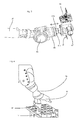
- FIG. 1 shows a representation of a plant 100 according to the invention for the production of plastic containers.
- This system has a heating device 50, which in turn has a transport device 49 for transporting the plastic preforms 10.
- This transport device may be a circulating conveyor chain, on which a plurality of holding elements for holding the plastic preforms, such as holding thorns (not shown), is arranged.
- the reference numeral 1 indicates a forming device for forming the plastic preforms to the plastic containers.
- This forming device is in particular a so-called stretch blow molding machine.
- this forming device preferably also has a loading device for acting on the plastic preforms with a gaseous medium and in particular with blast air.
- the device preferably also has a stretching rod in order to stretch the plastic preforms in their longitudinal direction.
- the reference numeral 2 refers to a transport device for transporting the plastic preforms.
- This transport device has a station carrier 12, on which a plurality of forming stations 8 is arranged.
- This station carrier is a so-called blowing wheel on which the individual forming stations 8 are arranged, in particular on its outer circumference.
- the individual forming stations 8 each have blow mold carriers 16, on which blow molding devices 14 are in turn arranged (shown only schematically).
- the reference numeral 40 denotes a changing device which serves to change the blow molding devices 14.
- This changing device 40 here has a change arm 54, which, however, in FIG. 1 is shown in two different positions. In the horizontal position here, the change arm is suitable to replace the blow molding. In the in FIG. 1 As shown in the vertical illustration, the changeover arm is adapted to load elements of the heating device, such as the heating mandrels.
- Reference numeral 70 denotes a first magazine device, in which elements of the heating device can be stored.
- the reference numeral 71 denotes a second magazine device, in which elements of the forming device, in particular the blow molding devices, can be stored.
- the changing device that is used for changing the blow molding in the device 1 is thus also used for changing, for example, heating mandrels and shielding plates in the heating device 50. In this way, the existing changing device can continue to be used and better utilized.
- a change device 40 or a robot preferably takes over the change of the sets completely.
- the changing device 40 is fixedly arranged here between the heating device 50 and the forming device 1 and can reach both machine modules with the changing arm 54.
- the change arm is here with a removable treatment head 51, 53 equipped, which makes it possible to change the handling device or the gripping element independently and store.
- at least one treatment head for the heating device and at least one treatment head for the shaping device are thus provided here.
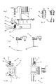
- Figures 2 and 3 show an example of such a replaceable treatment head.
- a carrier 85 is arranged on the changeover arm 54 via a pivot joint 83, and the treatment head 51 is again interchangeably arranged on this support 85.
- the reference numeral 87 denotes a motor with which a rotary or pivoting movement of the treatment head 51 or 53 can be achieved.
- the treatment head or the exchange element 51 can be detached from the carrier 85 and thus also from the arm 54.
- Reference numeral 52 denotes a gripping device.
- FIG. 2 The illustration shown is a treatment device or a handling element which serves for changing elements of the heating device 50, such as the retaining mandrels or the shielding elements.
- treatment heads for example, including their media clutches for pneumatics or hydraulics or for the control and power supply can be stored and coupled independently of the change arm.
- the reference numerals 51 a and 51 b refer to connecting elements, via which, for example, a hydraulic or pneumatic or even an electrical connection can be made.
- these connecting elements 51 a, b are preferably designed such that the treatment head can be arranged by a rectilinear relative movement in the direction X on the carrier 85 and / or can be detached from this carrier.
- locking elements may be provided which enable locking of the treatment head to the support 85.
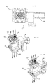
- FIG. 4 shows an example of a combined treatment facility.
- two exchangeable elements 51 and 53 are provided, which are arranged together on the arm 54.
- the exchangeable element 53 or the treatment head 53 can be used for a blow mold change, and the treatment element 51 can be used for a change of heating mandrels. This has the advantage that the treatment heads 51 and 53 on the robot arm 54 need not be exchanged.
- FIG. 5 schematically shows a further arrangement 100 for producing plastic containers.
- the changing device 40 is movably arranged, for example on a freely movable carriage or on rails.
- the changing device 40 can be used both for the heating device 50 and for the forming device 1 and possibly even for downstream units, such as a filling device 120. In this way, it would even be possible to use the changing device for a complete system.
- the changing device is not provided on a trolley, which is flexibly movable, but on a fixed rail or guide system.
- This guide system makes it possible to move the changing device at defined locations on defined routes. Also in this way, a central area for stocking the clothing parts, i. a cloth storage be created.
- the changing device gets in this case always preferred for the respective change necessary sets of sets on their vehicles and buffers these preferably in the meantime. In this way, it is possible to dispense with space-consuming storage magazines on the machines on site, wherein such storage magazines often have the disadvantage that they impede access to the machine.
- the changing device preferably has a magazine for accommodating elements of the forming device and / or elements of the heating device, which is at least temporarily coupled to the changing device and can thus be moved together with the latter.
- FIG. 6 shows an example of a changing device 40.
- the changing device 40 is provided, for example, stationary. This can intervene in the area of a heating device 50 and take over there, for example, heating mandrels. These parts can be stored in a magazine 70.
- the changer 40 it is possible for the changer 40 to attach (to change) a treatment head attached to the robotic arm to a heating mandrel and a shield plate in a rear portion of the heater.
- Reference numeral 56 denotes another arm the changing device, on which in turn the arm 54 (pivotally or generally movable) is arranged.
- FIG. 7 shows a more detailed representation of a change region of a heating device 50.
- This heating device in this case has a plurality of carriers 92, on each of which Bankdorne 96 are arranged.
- Reference numeral 98 refers to shielding elements, such as shielding plates, which are also removable from the carrier 92. By means of an unlocking device 90, the detachment of the shielding plates can be initiated.
- FIG. 8 shows the respective heating mandrels 96, which are releasably secured to respective bodies 94. At the right in FIG. 8 As shown, the heating mandrel 96 has just been removed.
- FIG. 9 shows the detachment of a shielding element 98, such as a shield plate (also from the carrier 92). It is possible that a fixed arrangement in the heating device for the heating mandrel, 96 and the shield plate 98 also provides for unlocking the trimmings.
- the opening movements can be initiated here, for example via pneumatic cylinders. Subsequently, the clothing parts can be picked up by the handling of the changing device and used again.
- FIGS. 10 and 11 show a treatment device 51 and 53.
- these treatment facilities or the treatment heads are constructed so that they can simultaneously accommodate at least two shield plates 98 and at least two Schudorne 96.
- these treatment heads are constructed mirror-symmetrically. In this way, the changing device after removing a set of clothing A can be pivoted by 180 ° to load a set of clothing B or to install.
- a drive device 95 which allows this pivoting or rotational movement of the treatment head 53.
- FIGS. 12-14 show three representations of such a treatment head 53.
- This treatment head has a base support 91, which - as mentioned above - by 180 ° by a drive 95 is pivotable.
- On both sides of this head can each the sets to be changed are arranged.
- clamping mechanisms may be provided, which for the purpose of transporting, for example, the shield plates 98 and the mandrels 96 temporarily hold.
- these are active holding elements, ie an engagement with the components to be changed can be loosened or locked.
- the reference numeral 103 denotes an engagement element movable relative to the base support, by means of which a support with the shielding elements and / or the heating mandrels 96 can be produced.
- this engagement element can be moved by means of pneumatic, hydraulic and / or electrical drive means.
- FIG. 15 shows a further illustration for illustrating a change of clothing parts of the heating device 50.
- the changing device 40 is disposed in a protective housing 80.
- a magazine magazine 70 is used as a magazine, which itself has a transport device 75 for transporting the clothing parts.
- the advantage of such a storage magazine over a fixed storage system is that the storage location in the room can always be the same and thus unnecessarily long travels and travel time can be avoided.
- FIG. 16 shows a detailed view of this set magazine 70.
- this set of magazines is able to arrange at each Magazinglied at least two Schudorne and at least two shielding plates. In this way, a replacement of the clothing parts can be facilitated.
- the reference numerals 97 each identify carriers for the relevant clothing parts.
- FIG. 17 shows a representation to illustrate a change of fittings.
- the change arm 54 by means of the respective joints substantially vertically (see double arrow Y) moves upward to replace the clothing parts, here Bankdorne 96 and shield plates 98.
- the existing clothing parts 96 and 98 it is possible for the existing clothing parts 96 and 98 to be removed first, and then the interchangeable element 53 to be rotated by 180 ° in order to immediately arrange the new clothing parts on the heating device 50.
- FIG. 18 shows a rough schematic representation of a system according to the invention 1.
- a blow molding machine 1 is provided, but next to another Treatment device 110 here in the form of a labeling machine.
- a filling device 120 is provided.
- the changing device 40 can be moved between the devices 1, 110 and 120 in order to perform treatment tasks there.
- the reference numeral 140 refers to a clothing storage in which, for example, different parts of clothing such as gripping elements or retaining thorns can be stored.
- the changing device 40 is movable between a first device 1 for forming plastic preforms into plastic containers and a second device 1 for converting plastic preforms into plastic containers, in order in this way alternatively to perform changing operations or other treatment operations on these two devices.
Priority Applications (2)
| Application Number | Priority Date | Filing Date | Title |
|---|---|---|---|
| EP17206826.4A EP3311978A1 (fr) | 2014-03-10 | 2015-03-10 | Dispositif et procédé destinés à la transformation d'ébauches en plastique en récipients en plastique à l'aide de dispositif de changement automatique pour des parties de garnitures |
| EP17190108.5A EP3284577B1 (fr) | 2014-03-10 | 2015-03-10 | Dispositif et procédé destinés au moulage d'ébauches en plastique en récipients en plastique à l'aide de dispositif de changement d'outillage |
Applications Claiming Priority (1)
| Application Number | Priority Date | Filing Date | Title |
|---|---|---|---|
| DE102014103159.8A DE102014103159A1 (de) | 2014-03-10 | 2014-03-10 | Vorrichtung und Verfahren zum Umformen von Kunststoffvorformlingen zu Kunststoffbehältnissen mit automatischer Wechseleinrichtung für Garniturenteile |
Related Child Applications (4)
| Application Number | Title | Priority Date | Filing Date |
|---|---|---|---|
| EP17190108.5A Division EP3284577B1 (fr) | 2014-03-10 | 2015-03-10 | Dispositif et procédé destinés au moulage d'ébauches en plastique en récipients en plastique à l'aide de dispositif de changement d'outillage |
| EP17190108.5A Division-Into EP3284577B1 (fr) | 2014-03-10 | 2015-03-10 | Dispositif et procédé destinés au moulage d'ébauches en plastique en récipients en plastique à l'aide de dispositif de changement d'outillage |
| EP17206826.4A Division-Into EP3311978A1 (fr) | 2014-03-10 | 2015-03-10 | Dispositif et procédé destinés à la transformation d'ébauches en plastique en récipients en plastique à l'aide de dispositif de changement automatique pour des parties de garnitures |
| EP17206826.4A Division EP3311978A1 (fr) | 2014-03-10 | 2015-03-10 | Dispositif et procédé destinés à la transformation d'ébauches en plastique en récipients en plastique à l'aide de dispositif de changement automatique pour des parties de garnitures |
Publications (2)
| Publication Number | Publication Date |
|---|---|
| EP2918391A1 true EP2918391A1 (fr) | 2015-09-16 |
| EP2918391B1 EP2918391B1 (fr) | 2018-10-31 |
Family
ID=52630294
Family Applications (3)
| Application Number | Title | Priority Date | Filing Date |
|---|---|---|---|
| EP17206826.4A Pending EP3311978A1 (fr) | 2014-03-10 | 2015-03-10 | Dispositif et procédé destinés à la transformation d'ébauches en plastique en récipients en plastique à l'aide de dispositif de changement automatique pour des parties de garnitures |
| EP15158527.0A Active EP2918391B1 (fr) | 2014-03-10 | 2015-03-10 | Dispositif et procédé de transformation d'ébauches en matière synthétique en récipients en plastique à l'aide de dispositif de changement automatique pour des parties de garnitures |
| EP17190108.5A Active EP3284577B1 (fr) | 2014-03-10 | 2015-03-10 | Dispositif et procédé destinés au moulage d'ébauches en plastique en récipients en plastique à l'aide de dispositif de changement d'outillage |
Family Applications Before (1)
| Application Number | Title | Priority Date | Filing Date |
|---|---|---|---|
| EP17206826.4A Pending EP3311978A1 (fr) | 2014-03-10 | 2015-03-10 | Dispositif et procédé destinés à la transformation d'ébauches en plastique en récipients en plastique à l'aide de dispositif de changement automatique pour des parties de garnitures |
Family Applications After (1)
| Application Number | Title | Priority Date | Filing Date |
|---|---|---|---|
| EP17190108.5A Active EP3284577B1 (fr) | 2014-03-10 | 2015-03-10 | Dispositif et procédé destinés au moulage d'ébauches en plastique en récipients en plastique à l'aide de dispositif de changement d'outillage |
Country Status (4)
| Country | Link |
|---|---|
| US (1) | US10000027B2 (fr) |
| EP (3) | EP3311978A1 (fr) |
| CN (1) | CN104760262B (fr) |
| DE (1) | DE102014103159A1 (fr) |
Cited By (8)
| Publication number | Priority date | Publication date | Assignee | Title |
|---|---|---|---|---|
| WO2017103273A1 (fr) * | 2015-12-18 | 2017-06-22 | Krones Ag | Dispositif de déformation de préformes en matière plastique pour produire des récipients en matière plastique, muni d'un dispositif de changement de moule de conception modulaire |
| WO2017103287A1 (fr) * | 2015-12-18 | 2017-06-22 | Krones Ag | Remplacement de moules de soufflage sur des machines de moulage par soufflage |
| WO2018206753A1 (fr) * | 2017-05-11 | 2018-11-15 | Krones Ag | Procédé de stérilisation d'une machine de moulage par soufflage et machine de moulage par soufflage |
| DE102017119817A1 (de) * | 2017-08-29 | 2019-02-28 | Krones Ag | Vorrichtung und Verfahren zum An- und Abkuppeln von Medienkupplungen an der Bodenform |
| WO2019048677A1 (fr) * | 2017-09-08 | 2019-03-14 | Krones Ag | Installation flexible de traitement de récipients |
| DE202018106385U1 (de) * | 2018-11-09 | 2020-02-12 | Krones Ag | Vorrichtung zum Erwärmen von Kunststoffvorformlingen |
| WO2020074145A1 (fr) * | 2018-10-12 | 2020-04-16 | Krones Ag | Procédé pour l'utilisation d'un système robotique et système robotique pour une installation de traitement de récipients |
| US11541589B2 (en) | 2017-08-02 | 2023-01-03 | Krones Ag | Apparatus and method for coupling and uncoupling media couplings on the base mould |
Families Citing this family (26)
| Publication number | Priority date | Publication date | Assignee | Title |
|---|---|---|---|---|
| FR3034410B1 (fr) | 2015-04-02 | 2020-10-23 | Gebo Packaging Solutions France | Dispositif de convoyage par chariot autonome |
| DE102015114947A1 (de) * | 2015-09-07 | 2017-03-09 | Krones Ag | Vorrichtung und Verfahren zum Behandeln von Behältnissen mit rückfragenden Behandlungseinrichtungen |
| DE102015116073A1 (de) * | 2015-09-23 | 2017-03-23 | Krones Ag | Verfahren und Vorrichtung zur Durchführung von Umstellvorgängen bei Vorrichtungen zum Herstellen von Getränkebehältnissen |
| US10576680B2 (en) * | 2015-11-19 | 2020-03-03 | The Boeing Company | Modular thermoforming system |
| DE102015122324A1 (de) | 2015-12-18 | 2017-06-22 | Krones Ag | Wechsel von Blasformen bei Blasformmaschinen |
| CN107303671A (zh) * | 2016-04-19 | 2017-10-31 | 上海技美科技股份有限公司 | 协作机器人 |
| FR3062335B1 (fr) * | 2017-07-21 | 2021-03-19 | Sidel Participations | Procede de maintenance d'une installation de formage de recipients, incluant une procedure de resynchronisation |
| DE102017119816A1 (de) * | 2017-08-29 | 2019-02-28 | Krones Ag | Vorrichtung und Verfahren zum Bedienen von Medienkupplungen an einer Blasform |
| JP7245603B2 (ja) * | 2017-11-10 | 2023-03-24 | 株式会社安川電機 | 教示装置、ロボットシステムおよび教示方法 |
| DE102017129847A1 (de) * | 2017-12-13 | 2019-06-27 | Krones Ag | Vorrichtung und Verfahren zum Behandeln von Behältnissen mit fahrerlosen-Transportsystem |
| CN107914132A (zh) * | 2017-12-20 | 2018-04-17 | 山东大学深圳研究院 | 一种鼠标外壳拆卸装置 |
| CN112004695A (zh) | 2018-02-21 | 2020-11-27 | 奥特莱德科技公司 | 用于自动卡车及牵引拖车的自动操作和处理的系统和方法 |
| US11707955B2 (en) | 2018-02-21 | 2023-07-25 | Outrider Technologies, Inc. | Systems and methods for automated operation and handling of autonomous trucks and trailers hauled thereby |
| DE102018217471A1 (de) * | 2018-10-12 | 2020-04-16 | Krones Ag | Modulares Robotersystem für eine Behälterverarbeitungsanlage |
| CN109352961A (zh) * | 2018-10-23 | 2019-02-19 | 佛山美石机械有限公司 | 一种吹瓶机旋转取瓶机械手 |
| US11858491B2 (en) | 2018-10-30 | 2024-01-02 | Outrider Technologies, Inc. | System and method for controlling braking functions in an autonomous vehicle |
| FR3090458B1 (fr) * | 2018-12-21 | 2021-01-15 | Sidel Participations | Dispositif de remplacement de nez de tournette d'un four d'une installation de soufflage de préformes et procédé correspondant |
| CN110682271B (zh) * | 2019-09-03 | 2023-04-04 | 贵州航天电器股份有限公司 | 一种用于圆形连接器生产线载具更换销钉的设备及方法 |
| DE102019128019A1 (de) * | 2019-10-17 | 2021-04-22 | Krones Ag | Automatischer Garniturwechsel in einer Getränkeabfüllanlage |
| DE102020105990A1 (de) | 2020-03-05 | 2021-09-09 | Framatome Gmbh | Erfassungsvorrichtung zum Erfassen einer Position eines beweglichen Objekts |
| DE102020109203A1 (de) * | 2020-04-02 | 2021-10-07 | STG Stanztechnik GmbH & Co. KG | Spritzgusssystem und Verfahren zur Herstellung von Formteilen aus spritzfähigen Formmassen |
| WO2022051329A1 (fr) * | 2020-09-01 | 2022-03-10 | Outrider Technologies, Inc. | Systèmes et procédés pour le fonctionnement et la manipulation automatisés de camions autonomes et remorques tirées par ceux-ci |
| CN112518718A (zh) * | 2020-11-26 | 2021-03-19 | 苏州鑫睿益荣信息技术有限公司 | 一种基于机械手的自动上下料及清洗系统及加工方法 |
| FR3131288A1 (fr) * | 2021-12-29 | 2023-06-30 | Sidel Participations | Procede de remplacements d'organes de prehension de preformes et installation de convoyage associee |
| DE102022117742A1 (de) | 2022-07-15 | 2024-01-18 | Krones Aktiengesellschaft | Vorrichtung und Verfahren zum Umformen von Kunststoffvorformlingen zu Kunststoffbehältnissen mit Wechselroboter |
| DE102022125324A1 (de) * | 2022-09-30 | 2024-04-04 | Krones Aktiengesellschaft | Anlage zum Herstellen von Kunststoffbehältnissen mit universal einsetzbarem Wechselroboter und Verfahren hierzu |
Citations (4)
| Publication number | Priority date | Publication date | Assignee | Title |
|---|---|---|---|---|
| WO2011026963A1 (fr) * | 2009-09-07 | 2011-03-10 | Sidel Participations | Procede de changement des empreintes de moulage d ' une station de soufflage de recipients en plastique et dispositif de stockage dynamique |
| WO2012120031A1 (fr) * | 2011-03-08 | 2012-09-13 | Sidel Participations | Systeme d'assistance au changement de moule d'unite de moulage d'une machine de fabrication de recipients |
| FR2990639A1 (fr) * | 2012-05-21 | 2013-11-22 | Sidel Participations | "installation pour la fabrication de recipients comportant un robot agence pour intervenir sur au moins deux unites" |
| EP2878423A1 (fr) * | 2013-11-26 | 2015-06-03 | Krones AG | Machine de formage par soufflage équipée de robots de remplacement et d'un dispositif de préhension, et son procédé de fonctionnement |
Family Cites Families (9)
| Publication number | Priority date | Publication date | Assignee | Title |
|---|---|---|---|---|
| SE452428B (sv) * | 1983-07-11 | 1987-11-30 | Asea Ab | Robotinstallation for montering |
| JP2571754Y2 (ja) * | 1992-04-14 | 1998-05-18 | 株式会社ヒロテック | 把持具交換装置 |
| DE102007037400A1 (de) * | 2007-08-08 | 2009-02-12 | Krones Ag | Blasmaschine für Behälter und Dornhalter |
| FR2921294A1 (fr) * | 2007-09-24 | 2009-03-27 | Inergy Automotive Systems Res | Procede de fabrication d'un corps creux en matiere plastique dispositif et appareillage pour sa mise en oeuvre |
| DE102009023726A1 (de) * | 2009-06-03 | 2010-12-09 | Krones Ag | Blasmaschine und Wechselautomat |
| DE102009039696A1 (de) * | 2009-09-02 | 2011-03-24 | Krones Ag | Vorrichtung zum Umformen von Kunststoffbehältnissen mit einer Blasform |
| DE102009039700A1 (de) | 2009-09-02 | 2011-03-10 | Krones Ag | Magazinvorrichtung zur Aufbewahrung von Blasformen |
| DE102009040977B4 (de) | 2009-09-11 | 2022-12-15 | Krones Aktiengesellschaft | Behältnisbehandlungsanlage und ein Behältnisbehandlungsverfahren zum Behandeln von mit einem Produkt befüllbaren Behältnissen |
| DE102011054890A1 (de) * | 2011-10-28 | 2013-05-02 | Krones Aktiengesellschaft | Behälterbehandlungsanlage und Handhabungsvorrichtung |
-
2014
- 2014-03-10 DE DE102014103159.8A patent/DE102014103159A1/de active Pending
-
2015
- 2015-03-09 CN CN201510102189.XA patent/CN104760262B/zh active Active
- 2015-03-10 EP EP17206826.4A patent/EP3311978A1/fr active Pending
- 2015-03-10 US US14/643,706 patent/US10000027B2/en active Active
- 2015-03-10 EP EP15158527.0A patent/EP2918391B1/fr active Active
- 2015-03-10 EP EP17190108.5A patent/EP3284577B1/fr active Active
Patent Citations (4)
| Publication number | Priority date | Publication date | Assignee | Title |
|---|---|---|---|---|
| WO2011026963A1 (fr) * | 2009-09-07 | 2011-03-10 | Sidel Participations | Procede de changement des empreintes de moulage d ' une station de soufflage de recipients en plastique et dispositif de stockage dynamique |
| WO2012120031A1 (fr) * | 2011-03-08 | 2012-09-13 | Sidel Participations | Systeme d'assistance au changement de moule d'unite de moulage d'une machine de fabrication de recipients |
| FR2990639A1 (fr) * | 2012-05-21 | 2013-11-22 | Sidel Participations | "installation pour la fabrication de recipients comportant un robot agence pour intervenir sur au moins deux unites" |
| EP2878423A1 (fr) * | 2013-11-26 | 2015-06-03 | Krones AG | Machine de formage par soufflage équipée de robots de remplacement et d'un dispositif de préhension, et son procédé de fonctionnement |
Cited By (12)
| Publication number | Priority date | Publication date | Assignee | Title |
|---|---|---|---|---|
| WO2017103273A1 (fr) * | 2015-12-18 | 2017-06-22 | Krones Ag | Dispositif de déformation de préformes en matière plastique pour produire des récipients en matière plastique, muni d'un dispositif de changement de moule de conception modulaire |
| WO2017103287A1 (fr) * | 2015-12-18 | 2017-06-22 | Krones Ag | Remplacement de moules de soufflage sur des machines de moulage par soufflage |
| US10953589B2 (en) | 2015-12-18 | 2021-03-23 | Krones Ag | Changing blow moulds in blow-moulding machines |
| WO2018206753A1 (fr) * | 2017-05-11 | 2018-11-15 | Krones Ag | Procédé de stérilisation d'une machine de moulage par soufflage et machine de moulage par soufflage |
| US11014283B2 (en) | 2017-05-11 | 2021-05-25 | Krones Ag | Method for sterilizing a blow molding machine, and blow molding machine |
| US11541589B2 (en) | 2017-08-02 | 2023-01-03 | Krones Ag | Apparatus and method for coupling and uncoupling media couplings on the base mould |
| DE102017119817A1 (de) * | 2017-08-29 | 2019-02-28 | Krones Ag | Vorrichtung und Verfahren zum An- und Abkuppeln von Medienkupplungen an der Bodenform |
| WO2019048677A1 (fr) * | 2017-09-08 | 2019-03-14 | Krones Ag | Installation flexible de traitement de récipients |
| US11260574B2 (en) | 2017-09-08 | 2022-03-01 | Krones Ag | Flexible plant for treating containers |
| WO2020074145A1 (fr) * | 2018-10-12 | 2020-04-16 | Krones Ag | Procédé pour l'utilisation d'un système robotique et système robotique pour une installation de traitement de récipients |
| CN112823082A (zh) * | 2018-10-12 | 2021-05-18 | 克朗斯股份公司 | 使用机器人系统的方法和用于容器处理设施的机器人系统 |
| DE202018106385U1 (de) * | 2018-11-09 | 2020-02-12 | Krones Ag | Vorrichtung zum Erwärmen von Kunststoffvorformlingen |
Also Published As
| Publication number | Publication date |
|---|---|
| US10000027B2 (en) | 2018-06-19 |
| EP3284577A2 (fr) | 2018-02-21 |
| EP2918391B1 (fr) | 2018-10-31 |
| EP3284577A3 (fr) | 2018-05-09 |
| US20150251366A1 (en) | 2015-09-10 |
| CN104760262A (zh) | 2015-07-08 |
| CN104760262B (zh) | 2017-08-29 |
| EP3311978A1 (fr) | 2018-04-25 |
| DE102014103159A1 (de) | 2015-09-24 |
| EP3284577B1 (fr) | 2024-01-24 |
Similar Documents
| Publication | Publication Date | Title |
|---|---|---|
| EP2918391B1 (fr) | Dispositif et procédé de transformation d'ébauches en matière synthétique en récipients en plastique à l'aide de dispositif de changement automatique pour des parties de garnitures | |
| EP2878424B1 (fr) | Machine de formage par soufflage équipée de robots de remplacement de formage par soufflage avec fonction de manutention supplémentaire | |
| EP3047959B1 (fr) | Dispositif de stockage destiné à stocker des moules de soufflage | |
| EP2878425B1 (fr) | Machine de formage par soufflage équipée de robots de remplacement et son procédé de fonctionnement | |
| EP2948292A1 (fr) | Procédé pour faire fonctionner une installation de traitement de contenants, et installation de traitement de contenants | |
| EP3150357A1 (fr) | Dispositif de stockage et procédé destiné à stocker des moules de soufflage | |
| EP2771245A1 (fr) | Installation de traitement de contenants et dispositif de manipulation | |
| EP2258534A1 (fr) | Souffleuse et automate de changement | |
| DE102015117292A1 (de) | Blasformmaschine mit automatisch betätigbarer Bodenankopplung | |
| EP3294523B1 (fr) | Remplacement de moules de soufflage sur des machines de moulage par soufflage | |
| EP3294521A1 (fr) | Dispositif de moulage par soufflage présentant un accouplement de fond à actionnement automatique et procédé pour le fonctionnement du dispositif associé | |
| WO2018202885A1 (fr) | Procédé servant à faire fonctionner un dispositif servant à façonner des préformes en matière plastique en des récipients en matière plastique, et dispositif | |
| DE102015117273A1 (de) | Blasformmaschine mit automatisch betätigbarer Bodenankopplung | |
| EP3678827A1 (fr) | Dispositif et procédé de transformation de préformes en matière plastique en récipients en matière plastique au moyen d'un robot de changement |
Legal Events
| Date | Code | Title | Description |
|---|---|---|---|
| PUAI | Public reference made under article 153(3) epc to a published international application that has entered the european phase |
Free format text: ORIGINAL CODE: 0009012 |
|
| AK | Designated contracting states |
Kind code of ref document: A1 Designated state(s): AL AT BE BG CH CY CZ DE DK EE ES FI FR GB GR HR HU IE IS IT LI LT LU LV MC MK MT NL NO PL PT RO RS SE SI SK SM TR |
|
| AX | Request for extension of the european patent |
Extension state: BA ME |
|
| 17P | Request for examination filed |
Effective date: 20160316 |
|
| RBV | Designated contracting states (corrected) |
Designated state(s): AL AT BE BG CH CY CZ DE DK EE ES FI FR GB GR HR HU IE IS IT LI LT LU LV MC MK MT NL NO PL PT RO RS SE SI SK SM TR |
|
| STAA | Information on the status of an ep patent application or granted ep patent |
Free format text: STATUS: EXAMINATION IS IN PROGRESS |
|
| 17Q | First examination report despatched |
Effective date: 20170706 |
|
| GRAP | Despatch of communication of intention to grant a patent |
Free format text: ORIGINAL CODE: EPIDOSNIGR1 |
|
| STAA | Information on the status of an ep patent application or granted ep patent |
Free format text: STATUS: GRANT OF PATENT IS INTENDED |
|
| RIC1 | Information provided on ipc code assigned before grant |
Ipc: B29C 49/48 20060101ALN20180320BHEP Ipc: B29C 49/28 20060101ALN20180320BHEP Ipc: B29C 49/42 20060101ALN20180320BHEP Ipc: B29C 49/06 20060101AFI20180320BHEP Ipc: B29C 31/00 20060101ALN20180320BHEP Ipc: B29C 33/30 20060101ALI20180320BHEP |
|
| INTG | Intention to grant announced |
Effective date: 20180406 |
|
| GRAJ | Information related to disapproval of communication of intention to grant by the applicant or resumption of examination proceedings by the epo deleted |
Free format text: ORIGINAL CODE: EPIDOSDIGR1 |
|
| STAA | Information on the status of an ep patent application or granted ep patent |
Free format text: STATUS: EXAMINATION IS IN PROGRESS |
|
| INTC | Intention to grant announced (deleted) | ||
| GRAS | Grant fee paid |
Free format text: ORIGINAL CODE: EPIDOSNIGR3 |
|
| STAA | Information on the status of an ep patent application or granted ep patent |
Free format text: STATUS: GRANT OF PATENT IS INTENDED |
|
| GRAP | Despatch of communication of intention to grant a patent |
Free format text: ORIGINAL CODE: EPIDOSNIGR1 |
|
| RIC1 | Information provided on ipc code assigned before grant |
Ipc: B29C 49/06 20060101AFI20180809BHEP Ipc: B29C 49/28 20060101ALN20180809BHEP Ipc: B29C 49/42 20060101ALN20180809BHEP Ipc: B29C 49/48 20060101ALN20180809BHEP Ipc: B29C 31/00 20060101ALN20180809BHEP Ipc: B29C 33/30 20060101ALI20180809BHEP |
|
| GRAA | (expected) grant |
Free format text: ORIGINAL CODE: 0009210 |
|
| STAA | Information on the status of an ep patent application or granted ep patent |
Free format text: STATUS: THE PATENT HAS BEEN GRANTED |
|
| INTG | Intention to grant announced |
Effective date: 20180912 |
|
| RIC1 | Information provided on ipc code assigned before grant |
Ipc: B29C 49/28 20060101ALN20180903BHEP Ipc: B29C 31/00 20060101ALN20180903BHEP Ipc: B29C 49/06 20060101AFI20180903BHEP Ipc: B29C 49/48 20060101ALN20180903BHEP Ipc: B29C 33/30 20060101ALI20180903BHEP Ipc: B29C 49/42 20060101ALN20180903BHEP |
|
| AK | Designated contracting states |
Kind code of ref document: B1 Designated state(s): AL AT BE BG CH CY CZ DE DK EE ES FI FR GB GR HR HU IE IS IT LI LT LU LV MC MK MT NL NO PL PT RO RS SE SI SK SM TR |
|
| REG | Reference to a national code |
Ref country code: CH Ref legal event code: EP Ref country code: GB Ref legal event code: FG4D Free format text: NOT ENGLISH |
|
| REG | Reference to a national code |
Ref country code: AT Ref legal event code: REF Ref document number: 1058846 Country of ref document: AT Kind code of ref document: T Effective date: 20181115 |
|
| REG | Reference to a national code |
Ref country code: IE Ref legal event code: FG4D Free format text: LANGUAGE OF EP DOCUMENT: GERMAN |
|
| REG | Reference to a national code |
Ref country code: DE Ref legal event code: R096 Ref document number: 502015006636 Country of ref document: DE |
|
| REG | Reference to a national code |
Ref country code: NL Ref legal event code: MP Effective date: 20181031 |
|
| REG | Reference to a national code |
Ref country code: LT Ref legal event code: MG4D |
|
| PG25 | Lapsed in a contracting state [announced via postgrant information from national office to epo] |
Ref country code: HR Free format text: LAPSE BECAUSE OF FAILURE TO SUBMIT A TRANSLATION OF THE DESCRIPTION OR TO PAY THE FEE WITHIN THE PRESCRIBED TIME-LIMIT Effective date: 20181031 Ref country code: PL Free format text: LAPSE BECAUSE OF FAILURE TO SUBMIT A TRANSLATION OF THE DESCRIPTION OR TO PAY THE FEE WITHIN THE PRESCRIBED TIME-LIMIT Effective date: 20181031 Ref country code: LV Free format text: LAPSE BECAUSE OF FAILURE TO SUBMIT A TRANSLATION OF THE DESCRIPTION OR TO PAY THE FEE WITHIN THE PRESCRIBED TIME-LIMIT Effective date: 20181031 Ref country code: NO Free format text: LAPSE BECAUSE OF FAILURE TO SUBMIT A TRANSLATION OF THE DESCRIPTION OR TO PAY THE FEE WITHIN THE PRESCRIBED TIME-LIMIT Effective date: 20190131 Ref country code: ES Free format text: LAPSE BECAUSE OF FAILURE TO SUBMIT A TRANSLATION OF THE DESCRIPTION OR TO PAY THE FEE WITHIN THE PRESCRIBED TIME-LIMIT Effective date: 20181031 Ref country code: BG Free format text: LAPSE BECAUSE OF FAILURE TO SUBMIT A TRANSLATION OF THE DESCRIPTION OR TO PAY THE FEE WITHIN THE PRESCRIBED TIME-LIMIT Effective date: 20190131 Ref country code: LT Free format text: LAPSE BECAUSE OF FAILURE TO SUBMIT A TRANSLATION OF THE DESCRIPTION OR TO PAY THE FEE WITHIN THE PRESCRIBED TIME-LIMIT Effective date: 20181031 Ref country code: FI Free format text: LAPSE BECAUSE OF FAILURE TO SUBMIT A TRANSLATION OF THE DESCRIPTION OR TO PAY THE FEE WITHIN THE PRESCRIBED TIME-LIMIT Effective date: 20181031 Ref country code: IS Free format text: LAPSE BECAUSE OF FAILURE TO SUBMIT A TRANSLATION OF THE DESCRIPTION OR TO PAY THE FEE WITHIN THE PRESCRIBED TIME-LIMIT Effective date: 20190228 |
|
| PG25 | Lapsed in a contracting state [announced via postgrant information from national office to epo] |
Ref country code: PT Free format text: LAPSE BECAUSE OF FAILURE TO SUBMIT A TRANSLATION OF THE DESCRIPTION OR TO PAY THE FEE WITHIN THE PRESCRIBED TIME-LIMIT Effective date: 20190301 Ref country code: RS Free format text: LAPSE BECAUSE OF FAILURE TO SUBMIT A TRANSLATION OF THE DESCRIPTION OR TO PAY THE FEE WITHIN THE PRESCRIBED TIME-LIMIT Effective date: 20181031 Ref country code: GR Free format text: LAPSE BECAUSE OF FAILURE TO SUBMIT A TRANSLATION OF THE DESCRIPTION OR TO PAY THE FEE WITHIN THE PRESCRIBED TIME-LIMIT Effective date: 20190201 Ref country code: AL Free format text: LAPSE BECAUSE OF FAILURE TO SUBMIT A TRANSLATION OF THE DESCRIPTION OR TO PAY THE FEE WITHIN THE PRESCRIBED TIME-LIMIT Effective date: 20181031 Ref country code: SE Free format text: LAPSE BECAUSE OF FAILURE TO SUBMIT A TRANSLATION OF THE DESCRIPTION OR TO PAY THE FEE WITHIN THE PRESCRIBED TIME-LIMIT Effective date: 20181031 Ref country code: NL Free format text: LAPSE BECAUSE OF FAILURE TO SUBMIT A TRANSLATION OF THE DESCRIPTION OR TO PAY THE FEE WITHIN THE PRESCRIBED TIME-LIMIT Effective date: 20181031 |
|
| PG25 | Lapsed in a contracting state [announced via postgrant information from national office to epo] |
Ref country code: DK Free format text: LAPSE BECAUSE OF FAILURE TO SUBMIT A TRANSLATION OF THE DESCRIPTION OR TO PAY THE FEE WITHIN THE PRESCRIBED TIME-LIMIT Effective date: 20181031 Ref country code: CZ Free format text: LAPSE BECAUSE OF FAILURE TO SUBMIT A TRANSLATION OF THE DESCRIPTION OR TO PAY THE FEE WITHIN THE PRESCRIBED TIME-LIMIT Effective date: 20181031 |
|
| REG | Reference to a national code |
Ref country code: DE Ref legal event code: R097 Ref document number: 502015006636 Country of ref document: DE |
|
| PG25 | Lapsed in a contracting state [announced via postgrant information from national office to epo] |
Ref country code: RO Free format text: LAPSE BECAUSE OF FAILURE TO SUBMIT A TRANSLATION OF THE DESCRIPTION OR TO PAY THE FEE WITHIN THE PRESCRIBED TIME-LIMIT Effective date: 20181031 Ref country code: SM Free format text: LAPSE BECAUSE OF FAILURE TO SUBMIT A TRANSLATION OF THE DESCRIPTION OR TO PAY THE FEE WITHIN THE PRESCRIBED TIME-LIMIT Effective date: 20181031 Ref country code: EE Free format text: LAPSE BECAUSE OF FAILURE TO SUBMIT A TRANSLATION OF THE DESCRIPTION OR TO PAY THE FEE WITHIN THE PRESCRIBED TIME-LIMIT Effective date: 20181031 Ref country code: SK Free format text: LAPSE BECAUSE OF FAILURE TO SUBMIT A TRANSLATION OF THE DESCRIPTION OR TO PAY THE FEE WITHIN THE PRESCRIBED TIME-LIMIT Effective date: 20181031 |
|
| PLBE | No opposition filed within time limit |
Free format text: ORIGINAL CODE: 0009261 |
|
| STAA | Information on the status of an ep patent application or granted ep patent |
Free format text: STATUS: NO OPPOSITION FILED WITHIN TIME LIMIT |
|
| 26N | No opposition filed |
Effective date: 20190801 |
|
| PG25 | Lapsed in a contracting state [announced via postgrant information from national office to epo] |
Ref country code: MC Free format text: LAPSE BECAUSE OF FAILURE TO SUBMIT A TRANSLATION OF THE DESCRIPTION OR TO PAY THE FEE WITHIN THE PRESCRIBED TIME-LIMIT Effective date: 20181031 Ref country code: SI Free format text: LAPSE BECAUSE OF FAILURE TO SUBMIT A TRANSLATION OF THE DESCRIPTION OR TO PAY THE FEE WITHIN THE PRESCRIBED TIME-LIMIT Effective date: 20181031 |
|
| REG | Reference to a national code |
Ref country code: CH Ref legal event code: PL |
|
| GBPC | Gb: european patent ceased through non-payment of renewal fee |
Effective date: 20190310 |
|
| PG25 | Lapsed in a contracting state [announced via postgrant information from national office to epo] |
Ref country code: LU Free format text: LAPSE BECAUSE OF NON-PAYMENT OF DUE FEES Effective date: 20190310 |
|
| REG | Reference to a national code |
Ref country code: BE Ref legal event code: MM Effective date: 20190331 |
|
| PG25 | Lapsed in a contracting state [announced via postgrant information from national office to epo] |
Ref country code: CH Free format text: LAPSE BECAUSE OF NON-PAYMENT OF DUE FEES Effective date: 20190331 Ref country code: GB Free format text: LAPSE BECAUSE OF NON-PAYMENT OF DUE FEES Effective date: 20190310 Ref country code: LI Free format text: LAPSE BECAUSE OF NON-PAYMENT OF DUE FEES Effective date: 20190331 Ref country code: IE Free format text: LAPSE BECAUSE OF NON-PAYMENT OF DUE FEES Effective date: 20190310 |
|
| PG25 | Lapsed in a contracting state [announced via postgrant information from national office to epo] |
Ref country code: BE Free format text: LAPSE BECAUSE OF NON-PAYMENT OF DUE FEES Effective date: 20190331 |
|
| PG25 | Lapsed in a contracting state [announced via postgrant information from national office to epo] |
Ref country code: TR Free format text: LAPSE BECAUSE OF FAILURE TO SUBMIT A TRANSLATION OF THE DESCRIPTION OR TO PAY THE FEE WITHIN THE PRESCRIBED TIME-LIMIT Effective date: 20181031 |
|
| PG25 | Lapsed in a contracting state [announced via postgrant information from national office to epo] |
Ref country code: MT Free format text: LAPSE BECAUSE OF FAILURE TO SUBMIT A TRANSLATION OF THE DESCRIPTION OR TO PAY THE FEE WITHIN THE PRESCRIBED TIME-LIMIT Effective date: 20181031 |
|
| REG | Reference to a national code |
Ref country code: AT Ref legal event code: MM01 Ref document number: 1058846 Country of ref document: AT Kind code of ref document: T Effective date: 20200310 |
|
| PG25 | Lapsed in a contracting state [announced via postgrant information from national office to epo] |
Ref country code: CY Free format text: LAPSE BECAUSE OF FAILURE TO SUBMIT A TRANSLATION OF THE DESCRIPTION OR TO PAY THE FEE WITHIN THE PRESCRIBED TIME-LIMIT Effective date: 20181031 |
|
| PG25 | Lapsed in a contracting state [announced via postgrant information from national office to epo] |
Ref country code: HU Free format text: LAPSE BECAUSE OF FAILURE TO SUBMIT A TRANSLATION OF THE DESCRIPTION OR TO PAY THE FEE WITHIN THE PRESCRIBED TIME-LIMIT; INVALID AB INITIO Effective date: 20150310 |
|
| PG25 | Lapsed in a contracting state [announced via postgrant information from national office to epo] |
Ref country code: AT Free format text: LAPSE BECAUSE OF NON-PAYMENT OF DUE FEES Effective date: 20200310 |
|
| PG25 | Lapsed in a contracting state [announced via postgrant information from national office to epo] |
Ref country code: MK Free format text: LAPSE BECAUSE OF FAILURE TO SUBMIT A TRANSLATION OF THE DESCRIPTION OR TO PAY THE FEE WITHIN THE PRESCRIBED TIME-LIMIT Effective date: 20181031 |
|
| PGFP | Annual fee paid to national office [announced via postgrant information from national office to epo] |
Ref country code: FR Payment date: 20230208 Year of fee payment: 9 |
|
| PGFP | Annual fee paid to national office [announced via postgrant information from national office to epo] |
Ref country code: IT Payment date: 20230213 Year of fee payment: 9 Ref country code: DE Payment date: 20230131 Year of fee payment: 9 |
|
| P01 | Opt-out of the competence of the unified patent court (upc) registered |
Effective date: 20230523 |
|
| PGFP | Annual fee paid to national office [announced via postgrant information from national office to epo] |
Ref country code: DE Payment date: 20240130 Year of fee payment: 10 |