EP2918364B1 - Verfahren zum schweissen von rohrverbindungen für hochtemperaturanwendungen - Google Patents
Verfahren zum schweissen von rohrverbindungen für hochtemperaturanwendungen Download PDFInfo
- Publication number
- EP2918364B1 EP2918364B1 EP15156500.9A EP15156500A EP2918364B1 EP 2918364 B1 EP2918364 B1 EP 2918364B1 EP 15156500 A EP15156500 A EP 15156500A EP 2918364 B1 EP2918364 B1 EP 2918364B1
- Authority
- EP
- European Patent Office
- Prior art keywords
- pipe section
- pipe
- austenitic
- thermal expansion
- coefficient
- Prior art date
- Legal status (The legal status is an assumption and is not a legal conclusion. Google has not performed a legal analysis and makes no representation as to the accuracy of the status listed.)
- Active
Links
- 238000003466 welding Methods 0.000 title claims description 46
- 238000000034 method Methods 0.000 title claims description 29
- 239000000463 material Substances 0.000 claims description 77
- 229910000831 Steel Inorganic materials 0.000 claims description 29
- 239000010959 steel Substances 0.000 claims description 29
- 239000000945 filler Substances 0.000 claims description 22
- 230000004927 fusion Effects 0.000 claims description 20
- 239000002184 metal Substances 0.000 description 7
- 229910052751 metal Inorganic materials 0.000 description 7
- 238000009659 non-destructive testing Methods 0.000 description 4
- 238000005452 bending Methods 0.000 description 2
- 230000007704 transition Effects 0.000 description 2
- OKTJSMMVPCPJKN-UHFFFAOYSA-N Carbon Chemical compound [C] OKTJSMMVPCPJKN-UHFFFAOYSA-N 0.000 description 1
- 238000013459 approach Methods 0.000 description 1
- 229910052799 carbon Inorganic materials 0.000 description 1
- 238000010438 heat treatment Methods 0.000 description 1
- 238000007689 inspection Methods 0.000 description 1
- 229910000734 martensite Inorganic materials 0.000 description 1
- 150000002739 metals Chemical class 0.000 description 1
- 239000002244 precipitate Substances 0.000 description 1
Images

Classifications
-
- B—PERFORMING OPERATIONS; TRANSPORTING
- B23—MACHINE TOOLS; METAL-WORKING NOT OTHERWISE PROVIDED FOR
- B23K—SOLDERING OR UNSOLDERING; WELDING; CLADDING OR PLATING BY SOLDERING OR WELDING; CUTTING BY APPLYING HEAT LOCALLY, e.g. FLAME CUTTING; WORKING BY LASER BEAM
- B23K11/00—Resistance welding; Severing by resistance heating
- B23K11/16—Resistance welding; Severing by resistance heating taking account of the properties of the material to be welded
-
- B—PERFORMING OPERATIONS; TRANSPORTING
- B23—MACHINE TOOLS; METAL-WORKING NOT OTHERWISE PROVIDED FOR
- B23K—SOLDERING OR UNSOLDERING; WELDING; CLADDING OR PLATING BY SOLDERING OR WELDING; CUTTING BY APPLYING HEAT LOCALLY, e.g. FLAME CUTTING; WORKING BY LASER BEAM
- B23K20/00—Non-electric welding by applying impact or other pressure, with or without the application of heat, e.g. cladding or plating
- B23K20/22—Non-electric welding by applying impact or other pressure, with or without the application of heat, e.g. cladding or plating taking account of the properties of the materials to be welded
- B23K20/227—Non-electric welding by applying impact or other pressure, with or without the application of heat, e.g. cladding or plating taking account of the properties of the materials to be welded with ferrous layer
-
- B—PERFORMING OPERATIONS; TRANSPORTING
- B23—MACHINE TOOLS; METAL-WORKING NOT OTHERWISE PROVIDED FOR
- B23K—SOLDERING OR UNSOLDERING; WELDING; CLADDING OR PLATING BY SOLDERING OR WELDING; CUTTING BY APPLYING HEAT LOCALLY, e.g. FLAME CUTTING; WORKING BY LASER BEAM
- B23K9/00—Arc welding or cutting
- B23K9/02—Seam welding; Backing means; Inserts
- B23K9/028—Seam welding; Backing means; Inserts for curved planar seams
- B23K9/0282—Seam welding; Backing means; Inserts for curved planar seams for welding tube sections
- B23K9/0284—Seam welding; Backing means; Inserts for curved planar seams for welding tube sections with an electrode working inside the tube
-
- B—PERFORMING OPERATIONS; TRANSPORTING
- B23—MACHINE TOOLS; METAL-WORKING NOT OTHERWISE PROVIDED FOR
- B23K—SOLDERING OR UNSOLDERING; WELDING; CLADDING OR PLATING BY SOLDERING OR WELDING; CUTTING BY APPLYING HEAT LOCALLY, e.g. FLAME CUTTING; WORKING BY LASER BEAM
- B23K11/00—Resistance welding; Severing by resistance heating
- B23K11/16—Resistance welding; Severing by resistance heating taking account of the properties of the material to be welded
- B23K11/20—Resistance welding; Severing by resistance heating taking account of the properties of the material to be welded of different metals
-
- B—PERFORMING OPERATIONS; TRANSPORTING
- B23—MACHINE TOOLS; METAL-WORKING NOT OTHERWISE PROVIDED FOR
- B23K—SOLDERING OR UNSOLDERING; WELDING; CLADDING OR PLATING BY SOLDERING OR WELDING; CUTTING BY APPLYING HEAT LOCALLY, e.g. FLAME CUTTING; WORKING BY LASER BEAM
- B23K20/00—Non-electric welding by applying impact or other pressure, with or without the application of heat, e.g. cladding or plating
- B23K20/002—Non-electric welding by applying impact or other pressure, with or without the application of heat, e.g. cladding or plating specially adapted for particular articles or work
-
- B—PERFORMING OPERATIONS; TRANSPORTING
- B23—MACHINE TOOLS; METAL-WORKING NOT OTHERWISE PROVIDED FOR
- B23K—SOLDERING OR UNSOLDERING; WELDING; CLADDING OR PLATING BY SOLDERING OR WELDING; CUTTING BY APPLYING HEAT LOCALLY, e.g. FLAME CUTTING; WORKING BY LASER BEAM
- B23K31/00—Processes relevant to this subclass, specially adapted for particular articles or purposes, but not covered by only one of the preceding main groups
- B23K31/003—Processes relevant to this subclass, specially adapted for particular articles or purposes, but not covered by only one of the preceding main groups relating to controlling of welding distortion
-
- B—PERFORMING OPERATIONS; TRANSPORTING
- B23—MACHINE TOOLS; METAL-WORKING NOT OTHERWISE PROVIDED FOR
- B23K—SOLDERING OR UNSOLDERING; WELDING; CLADDING OR PLATING BY SOLDERING OR WELDING; CUTTING BY APPLYING HEAT LOCALLY, e.g. FLAME CUTTING; WORKING BY LASER BEAM
- B23K31/00—Processes relevant to this subclass, specially adapted for particular articles or purposes, but not covered by only one of the preceding main groups
- B23K31/02—Processes relevant to this subclass, specially adapted for particular articles or purposes, but not covered by only one of the preceding main groups relating to soldering or welding
-
- B—PERFORMING OPERATIONS; TRANSPORTING
- B23—MACHINE TOOLS; METAL-WORKING NOT OTHERWISE PROVIDED FOR
- B23K—SOLDERING OR UNSOLDERING; WELDING; CLADDING OR PLATING BY SOLDERING OR WELDING; CUTTING BY APPLYING HEAT LOCALLY, e.g. FLAME CUTTING; WORKING BY LASER BEAM
- B23K33/00—Specially-profiled edge portions of workpieces for making soldering or welding connections; Filling the seams formed thereby
- B23K33/004—Filling of continuous seams
- B23K33/006—Filling of continuous seams for cylindrical workpieces
-
- B—PERFORMING OPERATIONS; TRANSPORTING
- B23—MACHINE TOOLS; METAL-WORKING NOT OTHERWISE PROVIDED FOR
- B23K—SOLDERING OR UNSOLDERING; WELDING; CLADDING OR PLATING BY SOLDERING OR WELDING; CUTTING BY APPLYING HEAT LOCALLY, e.g. FLAME CUTTING; WORKING BY LASER BEAM
- B23K37/00—Auxiliary devices or processes, not specially adapted to a procedure covered by only one of the preceding main groups
-
- F—MECHANICAL ENGINEERING; LIGHTING; HEATING; WEAPONS; BLASTING
- F16—ENGINEERING ELEMENTS AND UNITS; GENERAL MEASURES FOR PRODUCING AND MAINTAINING EFFECTIVE FUNCTIONING OF MACHINES OR INSTALLATIONS; THERMAL INSULATION IN GENERAL
- F16L—PIPES; JOINTS OR FITTINGS FOR PIPES; SUPPORTS FOR PIPES, CABLES OR PROTECTIVE TUBING; MEANS FOR THERMAL INSULATION IN GENERAL
- F16L13/00—Non-disconnectible pipe-joints, e.g. soldered, adhesive or caulked joints
- F16L13/02—Welded joints
-
- B—PERFORMING OPERATIONS; TRANSPORTING
- B23—MACHINE TOOLS; METAL-WORKING NOT OTHERWISE PROVIDED FOR
- B23K—SOLDERING OR UNSOLDERING; WELDING; CLADDING OR PLATING BY SOLDERING OR WELDING; CUTTING BY APPLYING HEAT LOCALLY, e.g. FLAME CUTTING; WORKING BY LASER BEAM
- B23K2101/00—Articles made by soldering, welding or cutting
- B23K2101/04—Tubular or hollow articles
- B23K2101/06—Tubes
-
- B—PERFORMING OPERATIONS; TRANSPORTING
- B23—MACHINE TOOLS; METAL-WORKING NOT OTHERWISE PROVIDED FOR
- B23K—SOLDERING OR UNSOLDERING; WELDING; CLADDING OR PLATING BY SOLDERING OR WELDING; CUTTING BY APPLYING HEAT LOCALLY, e.g. FLAME CUTTING; WORKING BY LASER BEAM
- B23K2103/00—Materials to be soldered, welded or cut
- B23K2103/02—Iron or ferrous alloys
- B23K2103/04—Steel or steel alloys
- B23K2103/05—Stainless steel
-
- B—PERFORMING OPERATIONS; TRANSPORTING
- B23—MACHINE TOOLS; METAL-WORKING NOT OTHERWISE PROVIDED FOR
- B23K—SOLDERING OR UNSOLDERING; WELDING; CLADDING OR PLATING BY SOLDERING OR WELDING; CUTTING BY APPLYING HEAT LOCALLY, e.g. FLAME CUTTING; WORKING BY LASER BEAM
- B23K2103/00—Materials to be soldered, welded or cut
- B23K2103/18—Dissimilar materials
- B23K2103/26—Alloys of Nickel and Cobalt and Chromium
Definitions
- the present invention is directed to a process for welding pipe connections for high temperature applications, particularly in power plants, comprising a first pipe section and a second pipe section, wherein the first pipe section is made of a ferritic material having a first coefficient of thermal expansion (CTE1) and wherein the second pipe section is made of an austenitic material having a second coefficient of thermal expansion (CTE2), which is different from the first coefficient of thermal expansion (CTE1), and wherein the weld joint is made of an austenitic filler material which has a third coefficient of thermal expansion (CTE3) which is in the range of the second coefficient of thermal expansion (CTE2).
- CTE1 first coefficient of thermal expansion
- CTE2 second coefficient of thermal expansion
- CTE3 third coefficient of thermal expansion
- the invention is further directed to such a pipe connection.
- DMW dissimilar metal weld
- the problem occurs at the fusion line between the austenitic filler material and the pipe section made of ferritic material that due to the differences in the coefficients of thermal expansion (CTE) the second pipe section made of an austenitic material and the weld joint material (filler material) made of an austenitic material are subject to a higher degree of elongation ( ⁇ ) than the first pipe section made of ferritic material.
- CTE coefficients of thermal expansion
- the second pipe section and the weld joint filler material are usually having the same coefficient of thermal expansion (CTE) or at least a coefficient of thermal expansion (CTE) in the same range, the connection between the second pipe section and the weld joint material is usually good.
- CTE coefficient of thermal expansion
- ⁇ elongation
- NDT non-destructive testing
- DMW dissimilar metal weld
- This object is achieved by providing a process for welding pipe connections for high temperature applications according to claim 1.
- This process comprises the steps of: axially aligning the first and second pipe sections to be connected, making an at least partially V-shaped welding groove open radially inwards, performing an inside welding process inside the first and second pipe sections to be connected.
- pipes are welded from the inside diameter rather than from the outside diameter.
- the weld joint material can be supported by the inclined surface of the at least partially V-shaped welding groove which is open radially inwards. Therefore, compressive stress is induced between the weld joint material and the first pipe section such that the lifetime and durability of the dissimilar metal weld connection can be improved.
- a pipe section made of ferritic C-steel is used as the first pipe section. It is particularly preferred that P91 steel or P22 steel is used as ferritic C-steel. Such steels are usually having preferred properties for high temperature applications such as applications in power plants.
- Another preferred alternative of the process for welding pipe connections provides that a pipe section made from austenitic steel or from Ni-based materials is used as the second pipe section.
- austenitic steel or an Ni-based material is used as the austenitic filler material.
- Such a pipe connection is characterized in that the welding groove is at least partially V-shaped and open radially inwards and that the first and second pipe sections are welded together via inside welding. Because the first and second pipe sections are welded together via inside welding by using an at least partially V-shaped welding groove open radially inwards, no additional normal stress is induced on the critical weld joint fusion line between the austenitic filler material and the first pipe section made of ferritic material.
- the weld joint material can be supported by the inclined surface of the at least partially V-shaped welding groove which is open radially inwards because of the inside welding process. Therefore, compressive stress is induced between the weld joint material and the first pipe section such that the lifetime and durability of the dissimilar metal weld connection can be improved by providing a pipe connection according to the invention.
- the welding groove is V-shaped or Y-shaped or is having any other inclined surface of a welding groove opening radially inwards such that the weld joint material can be supported by the inclined surface in order to produce compressive stress when the pipe connection is subject to high temperatures.
- the first pipe section is made of ferritic C-steel, wherein it is particularly preferred that the ferritic C-steel is P91 steel or P22 steel which are having preferred properties for high temperature power plant applications.
- the second pipe section is made of austenitic steel or an Ni-based material.
- the austenitic filler material is made of austenitic steel or an Ni-based material.
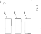
- Figure 1 illustrates a process chart for the process 100 according to the invention for welding pipe connections according to the invention which is shown in Figure 3 .
- a first pipe section 12 and a second pipe section 14 of a pipe connection 10 according to the invention are axially aligned in order to be connected.
- a second step S102 an at least partially V-shaped welding groove 16 is formed between the first pipe section 12 and the second pipe section 14 which is open radially inwards that is in the direction of a middle axis 18 shown by arrow 20.
- a third step S103 an inside welding process is performed inside the first and second pipe sections 12, 14 to be connected.
- pipes are welded from the inside diameter rather than from the outside diameter.
- the first pipe section 12 is made of a ferritic material, preferably of P91 or P22 steel (with CTE1 12.6 resp. 13.9 E-6/K) for high temperature applications
- the second pipe section 14 is made of an austenitic material, preferably of austenitic steel or an Ni-Based material, for example IN 625 (with CTE2 14.8 E-6/K).
- a weld joint 22 is made of austenitic weld joint filler material which is preferably austenitic steel or Ni-based material, for example ERNICr-3 (with CTE3 15.3 E-6/K). That means the coefficient of thermal expansion of the weld joint filler material is close (resp. more similar) to the coefficient of thermal expansion of the material of the second pipe section (difference between CTE3 and CTE2 is only 0.5 E-6/K) with respect to the coefficient of thermal expansion of the material of the first pipe section (difference between CTE3 and CTE1 is 2.7 resp. 1.4 E-6/K for the described materials).
- austenitic weld joint filler material which is preferably austenitic steel or Ni-based material, for example ERNICr-3 (with CTE3 15.3 E-6/K). That means the coefficient of thermal expansion of the weld joint filler material is close (resp. more similar) to the coefficient of thermal expansion of the material of the second pipe section (difference between CTE3
- a first pipe section made of the ferritic base materials P91 (CTE1 12.6 E-6/K) or P22 (CTE1 13.9 E-6/K) is connected to an austenitic pipe section, e.g. SS347H (CTE2 18.9 E-6/K) using a similar filler metal like SS347H with a CTE3 similar to that one of SS347H.
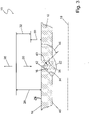
- FIG 2 is showing a pipe connection 10 according to the state of the art.
- the same reference numerals will be used for corresponding elements as in the pipe connection 10 according to the invention illustrated in Figure 3 .
- the pipe connection 10 is having a first pipe section 12 made of ferritic material and a second pipe section 14 made of austenitic material which are axially aligned around a middle axis 18.
- a welding groove 16 which is V-shaped is formed on the outside surface 24 of the pipe connection 10 and opens radially outwards in the direction of arrow 26.
- the welding groove 16 is filled with weld joint filler material of austenitic material which is forming the weld joint 22.
- the second pipe section 14 of austenitic material is having a higher CTE than the first pipe section 12 made of ferritic material.
- the elongation of the second pipe section 14 is marked by arrow 28, wherein the elongation of the first pipe section 12 is marked by arrow 30.
- the elongation 28 is bigger than the elongation 30, wherein the delta of the elongations 28, 30 is marked by arrow 32.
- the weld joint 22 is providing a good connection at the fusion line 34 between the second pipe section 14 and the weld joint 22 which are both made of austenitic material and having a CTE within the same range, that means they have similar CTE.
- the pipe connection 10 according to the invention overcomes these problems.
- the pipe connection 10 is substantially the same as the pipe connection 10 in Figure 2 , because the pipe sections 12, 14 and the weld joint 22 are made of the same material combination as the pipe connection 10 in Figure 2 .
- the welding groove 16, which is filled with weld joint filler material of austenitic material and forming the weld joint 22 is not opening radially outwards.
- the pipe connection 10 illustrated in Figure 3 is having a welding groove 16, which is V-shaped and formed on an inside surface 40 of the pipe connection 10 and opening radially inwards in the direction of the middle axis 18 depicted by arrow 20.
- the inclined surface 42 is arranged in an angle 44 to the outside surface 24 of the pipe connection 10.
- the movement is restricted by the inclined surface 42 which is exerting a counterforce on the weld joint 22.
- inside welding of a pipe connection 10 according to Figure 3 by performing the process 100 illustrated in Figure 1 and by providing a V-shaped welding groove 16 open radially inwards leads to reduced stress in the area of the weld joint 22. Compressive stress is induced on the fusion line 36 as depicted by arrow 43.
Claims (10)
- Verfahren (100) zum Schweißen von Rohrverbindungen (10) für Hochtemperaturanwendungen, insbesondere in Kraftwerken, mit einem ersten Rohrabschnitt (12) und einem zweiten Rohrabschnitt (14), wobei der erste Rohrabschnitt (12) aus einem ferritischen Material mit einem ersten Wärmeausdehnungskoeffizienten (CTE1) gefertigt ist und wobei der zweite Rohrabschnitt (14) aus einem austenitischen Material mit einem zweiten Wärmeausdehnungskoeffizienten (CTE2), der sich von dem ersten Wärmeausdehnungskoeffizienten (CTE1) unterscheidet, gefertigt ist;
wobei das Verfahren (100) die Schritte umfasst:- axiales Ausrichten der ersten und zweiten zu verbindenden Rohrabschnitte (12, 14);dadurch gekennzeichnet, dass das Verfahren ferner die Schritte umfasst:- Herstellen einer wenigstens teilweise V-förmigen Schweißnut (16), die radial nach innen offen ist;- Füllen der Schweißnut (16) mit einem Schweißnahtfüllmaterial aus austenitischem Material und Ausbilden einer Schweißnaht (22) durch Ausführen eines Innenschweißverfahrens im Inneren der ersten und zweiten zu verbindenden Rohrabschnitte (12, 14); wobei das austenitische Füllmaterial einen dritten Wärmeausdehnungskoeffizienten (CTE3) aufweist, der in Bezug auf den ersten Wärmeausdehnungskoeffizienten (CTE1) des Materials des ersten Rohrabschnitts (12) näher an dem zweiten Wärmeausdehnungskoeffizienten (CTE2) ist; wobei das Innenschweißverfahren so durchgeführt wird, dass die Schweißnaht (22) eine erste Schmelzlinie entlang des ersten Rohrabschnitts (12) und der Schweißnaht (22) und eine zweite Schmelzlinie entlang des zweiten Rohrabschnitts (14) und der Schweißnaht (22) aufweist. - Verfahren (100) zum Schweißen nach Anspruch 1, wobei ein aus ferritischem C-Stahl gefertigter Rohrabschnitt als erster Rohrabschnitt (12) verwendet wird.
- Verfahren (100) zum Schweißen nach Anspruch 2, wobei P91-Stahl oder P22-Stahl als ferritischer C-Stahl verwendet wird.
- Verfahren (100) zum Schweißen nach einem der vorangehenden Ansprüche, wobei ein Rohrabschnitt, der aus austenitischem Stahl oder aus Materialien auf Ni-Basis gefertigt ist, als zweiter Rohrabschnitt (14) verwendet wird.
- Verfahren (100) zum Schweißen nach einem der vorangehenden Ansprüche, wobei austenitischer Stahl oder ein Material auf Ni-Basis als das austenitische Füllmaterial verwendet wird.
- Rohrverbindung (10) für Hochtemperaturanwendungen, insbesondere in Kraftwerken; wobei die Rohrverbindung (10) einen ersten Rohrabschnitt (12) und einen zweiten Rohrabschnitt (14) umfasst, wobei der erste Rohrabschnitt (12) aus einem ferritischen Material mit einem ersten Wärmeausdehnungskoeffizienten (CTE1) gefertigt ist und wobei der zweite Rohrabschnitt (14) aus einem austenitischen Material mit einem zweiten Wärmeausdehnungskoeffizienten (CTE2), der sich von dem ersten Wärmeausdehnungskoeffizienten (CTE1) unterscheidet, gefertigt ist, dadurch gekennzeichnet, dass eine Schweißnaht (22) eine Schweißnut (16) der Rohrverbindung (10) ausfüllt und aus einem austenitischen Füllmaterial hergestellt ist, das einen dritten Wärmeausdehnungskoeffizienten (CTE3) aufweist; wobei die Schweißnaht (22) eine Verbindung zwischen dem ersten Rohrabschnitt (12) und dem zweiten Rohrabschnitt (14) herstellt, so dass die Schweißnaht (22) eine erste Schmelzlinie (34) entlang des ersten Rohrabschnitts (12) und der Schweißnaht (22) aufweist und eine zweite Schmelzlinie (36) entlang des zweiten Rohrabschnitts (14) und der Schweißnaht (22) aufweist; und wobei der dritte Wärmeausdehnungskoeffizient (CTE3) in Bezug auf den ersten Wärmeausdehnungskoeffizienten (CTE1) des Materials des ersten Rohrabschnitts (12) näher am zweiten Wärmeausdehnungskoeffizienten (CTE2) ist; und wobei die Schweißnut (16) wenigstens teilweise V-förmig und radial nach innen offen ist, und wobei der erste und der zweite Rohrabschnitt (12, 14) mittels Innenschweißen miteinander verschweißt sind.
- Rohrverbindung (10) nach Anspruch 6, wobei der erste Rohrabschnitt (12) aus ferritischem C-Stahl gefertigt ist.
- Rohrverbindung (10) nach Anspruch 7, wobei der ferritische C-Stahl P91-Stahl oder P22-Stahl ist.
- Rohrverbindung (10) nach einem der Ansprüche 6 bis 8, wobei der zweite Rohrabschnitt (14) aus austenitischem Stahl oder einem Material auf Ni-Basis gefertigt ist.
- Rohrverbindung (10) nach einem der Ansprüche 6 bis 9, wobei das austenitische Füllmaterial aus austenitischem Stahl oder einem Material auf Ni-Basis hergestellt ist.
Priority Applications (1)
| Application Number | Priority Date | Filing Date | Title |
|---|---|---|---|
| EP15156500.9A EP2918364B1 (de) | 2014-03-14 | 2015-02-25 | Verfahren zum schweissen von rohrverbindungen für hochtemperaturanwendungen |
Applications Claiming Priority (2)
| Application Number | Priority Date | Filing Date | Title |
|---|---|---|---|
| EP14159695 | 2014-03-14 | ||
| EP15156500.9A EP2918364B1 (de) | 2014-03-14 | 2015-02-25 | Verfahren zum schweissen von rohrverbindungen für hochtemperaturanwendungen |
Publications (2)
| Publication Number | Publication Date |
|---|---|
| EP2918364A1 EP2918364A1 (de) | 2015-09-16 |
| EP2918364B1 true EP2918364B1 (de) | 2022-08-17 |
Family
ID=50272479
Family Applications (1)
| Application Number | Title | Priority Date | Filing Date |
|---|---|---|---|
| EP15156500.9A Active EP2918364B1 (de) | 2014-03-14 | 2015-02-25 | Verfahren zum schweissen von rohrverbindungen für hochtemperaturanwendungen |
Country Status (6)
| Country | Link |
|---|---|
| US (1) | US20150258629A1 (de) |
| EP (1) | EP2918364B1 (de) |
| JP (1) | JP2015174147A (de) |
| KR (1) | KR20150107675A (de) |
| CN (2) | CN116174978A (de) |
| CA (1) | CA2884021A1 (de) |
Families Citing this family (5)
| Publication number | Priority date | Publication date | Assignee | Title |
|---|---|---|---|---|
| CN106232279B (zh) * | 2014-01-24 | 2020-07-07 | 电力研究所有限公司 | 阶梯式设计焊缝接头坡口 |
| US11339900B2 (en) | 2017-02-13 | 2022-05-24 | Webco Industries, Inc. | Work hardened welds and methods for same |
| CA3052815C (en) * | 2017-02-13 | 2021-11-23 | Webco Industries, Inc. | Work hardened welds and methods for same |
| CN111151842B (zh) * | 2020-01-10 | 2021-10-19 | 安泰环境工程技术有限公司 | 一种铁铝基金属间化合物微孔材料的焊接方法及其焊接件 |
| CN113084317B (zh) * | 2021-04-15 | 2022-05-17 | 中建安装集团有限公司 | 一种大直径高温管道安装调整方法 |
Citations (3)
| Publication number | Priority date | Publication date | Assignee | Title |
|---|---|---|---|---|
| US1313542A (en) * | 1916-12-12 | 1919-08-19 | Walter A Jones | Boiler tube and sheet joint. |
| JP3085877B2 (ja) * | 1995-04-14 | 2000-09-11 | 三菱重工業株式会社 | 小口径管内溶接装置 |
| US20090223053A1 (en) * | 2005-02-28 | 2009-09-10 | Electric Power Research Institute, Inc. | Method for repairing heat recovery steam generator tube-to-header damage |
Family Cites Families (8)
| Publication number | Priority date | Publication date | Assignee | Title |
|---|---|---|---|---|
| JPS5542148A (en) * | 1978-09-21 | 1980-03-25 | Mitsubishi Heavy Ind Ltd | Inconel welding method of dissimilar material joint |
| US4525620A (en) * | 1982-09-15 | 1985-06-25 | Allegheny Ludlum Steel Corporation | Method of welding ferritic and austenitic stainless steels and product thereof |
| DE19527634A1 (de) | 1995-07-28 | 1997-01-30 | Evt Energie & Verfahrenstech | Stumpfschweißverbindung |
| RU2158668C2 (ru) * | 1999-02-04 | 2000-11-10 | Открытое акционерное общество НПО Энергомаш им. акад. В.П. Глушко | Способ получения сварного соединения |
| JP2003090506A (ja) * | 2001-09-13 | 2003-03-28 | Babcock Hitachi Kk | ボイラ伝熱管異材継手溶接部の損傷診断法と装置 |
| US7371988B2 (en) * | 2004-10-22 | 2008-05-13 | Electric Power Research Institute, Inc. | Methods for extending the life of alloy steel welded joints by elimination and reduction of the HAZ |
| DE102011055282A1 (de) * | 2011-07-26 | 2013-01-31 | Alstom Technology Ltd. | Verfahren zum Schweißen von dünnwandigen Rohren mittels Spitzentemperaturanlassschweißen |
| EP2695695B1 (de) * | 2012-08-08 | 2018-01-03 | ARVOS GmbH | Verfahren zum Schweißen von Leitungen |
-
2015
- 2015-02-25 EP EP15156500.9A patent/EP2918364B1/de active Active
- 2015-03-05 CA CA2884021A patent/CA2884021A1/en not_active Abandoned
- 2015-03-13 JP JP2015050371A patent/JP2015174147A/ja active Pending
- 2015-03-13 KR KR1020150034893A patent/KR20150107675A/ko unknown
- 2015-03-13 US US14/657,177 patent/US20150258629A1/en not_active Abandoned
- 2015-03-13 CN CN202310043769.0A patent/CN116174978A/zh active Pending
- 2015-03-13 CN CN201510111463.XA patent/CN104907717A/zh active Pending
Patent Citations (3)
| Publication number | Priority date | Publication date | Assignee | Title |
|---|---|---|---|---|
| US1313542A (en) * | 1916-12-12 | 1919-08-19 | Walter A Jones | Boiler tube and sheet joint. |
| JP3085877B2 (ja) * | 1995-04-14 | 2000-09-11 | 三菱重工業株式会社 | 小口径管内溶接装置 |
| US20090223053A1 (en) * | 2005-02-28 | 2009-09-10 | Electric Power Research Institute, Inc. | Method for repairing heat recovery steam generator tube-to-header damage |
Non-Patent Citations (2)
| Title |
|---|
| JOUNGHOON LEE ET AL: "Mechanical Properties Evaluation in Inconel 82/182 Dissimilar Metal Welds", 19TH INTERNATIONAL CONFERENCE ON STRUCTURAL MECHANICS IN REACTOR TECHNOLOGY 2007 (SMIRT 19), 17 August 2007 (2007-08-17), XP055415516, ISBN: 978-1-61567-050-5, Retrieved from the Internet <URL:https://repository.lib.ncsu.edu/bitstream/handle/1840.20/31129/G04_4.pdf?sequence=1&isAllowed=y> [retrieved on 20171013] * |
| KING J F ET AL: "Development of an Improved Stainless Steel to Ferritic Steel Transition Joint", WELDING JOURNAL,, vol. 56, no. 11, 1 November 1977 (1977-11-01), pages 354 - s, XP001342150 * |
Also Published As
| Publication number | Publication date |
|---|---|
| CN116174978A (zh) | 2023-05-30 |
| US20150258629A1 (en) | 2015-09-17 |
| JP2015174147A (ja) | 2015-10-05 |
| CA2884021A1 (en) | 2015-09-14 |
| CN104907717A (zh) | 2015-09-16 |
| KR20150107675A (ko) | 2015-09-23 |
| EP2918364A1 (de) | 2015-09-16 |
Similar Documents
| Publication | Publication Date | Title |
|---|---|---|
| EP2918364B1 (de) | Verfahren zum schweissen von rohrverbindungen für hochtemperaturanwendungen | |
| EP3265266B2 (de) | System und verfahren zum verbinden durch reibungsschweissen eines ersten stahlelement mit einem zweiten stahlelement durch verwendung eines adaptierselementes aus ni-basierten legierungen | |
| EP3389919B1 (de) | Verbindungsverfahren und rohrverbindungsanordnung mit verbesserter ermüdungsfestigkeit von metallischen steigrohren | |
| US9737948B2 (en) | Method for welding thin-walled tubes by means of peak temperature temper welding | |
| RU2711168C2 (ru) | Способ изготовления трубного устройства, трубное устройство и печь, снабженная таким трубным устройством | |
| Della Rovere et al. | Local mechanical properties of radial friction welded supermartensitic stainless steel pipes | |
| CN107002914B (zh) | 流体导管元件以及用于形成流体导管元件的方法 | |
| US20020134452A1 (en) | Methods of girth welding high strength steel pipes to achieve pipeling crack arrestability | |
| JP2011125921A (ja) | 溶接継手部のクリープ強度向上構造 | |
| RU2449870C1 (ru) | Способ изготовления стальной сложнокомбинированной осесимметричной сварной конструкции, работающей под давлением | |
| KR100216867B1 (ko) | 버트용접조인트 | |
| RU2410593C2 (ru) | Способ соединения труб с внутренним покрытием | |
| JP6642925B2 (ja) | 溶接方法 | |
| Słania et al. | Causes of the cracks in the pipeline made of the 15HM steel | |
| US11976754B2 (en) | Flange connection having a weld ring gasket | |
| RU2544763C2 (ru) | Способ изготовления тонколистовых конструкций из молибдена или его сплавов | |
| US10590508B2 (en) | Method for manufacturing shaft body | |
| Ogata et al. | Creep Rupture Life Prediction of Grade 91 Circumferential Welded Tube Under Combined Internal Pressure With Axial Load | |
| Marimuthu et al. | Establishment of Testing Methodology for Forge Welded Tubular Products | |
| RU2213286C1 (ru) | Трубопровод (варианты) | |
| CN114813416A (zh) | 一种管线钢管服役阶段环焊接头软化合于使用性评价方法 | |
| Thielsch et al. | Failure analysis of superheater outlet header | |
| Masuyama et al. | Creep Degradation and Life Assessment of High Temperature Welds | |
| JP2019111576A (ja) | 溶接方法 | |
| JPH02137670A (ja) | 配管の補強溶接方法 |
Legal Events
| Date | Code | Title | Description |
|---|---|---|---|
| PUAI | Public reference made under article 153(3) epc to a published international application that has entered the european phase |
Free format text: ORIGINAL CODE: 0009012 |
|
| AK | Designated contracting states |
Kind code of ref document: A1 Designated state(s): AL AT BE BG CH CY CZ DE DK EE ES FI FR GB GR HR HU IE IS IT LI LT LU LV MC MK MT NL NO PL PT RO RS SE SI SK SM TR |
|
| AX | Request for extension of the european patent |
Extension state: BA ME |
|
| 17P | Request for examination filed |
Effective date: 20160315 |
|
| RBV | Designated contracting states (corrected) |
Designated state(s): AL AT BE BG CH CY CZ DE DK EE ES FI FR GB GR HR HU IE IS IT LI LT LU LV MC MK MT NL NO PL PT RO RS SE SI SK SM TR |
|
| RAP1 | Party data changed (applicant data changed or rights of an application transferred) |
Owner name: GENERAL ELECTRIC TECHNOLOGY GMBH |
|
| RAP1 | Party data changed (applicant data changed or rights of an application transferred) |
Owner name: ANSALDO ENERGIA IP UK LIMITED |
|
| STAA | Information on the status of an ep patent application or granted ep patent |
Free format text: STATUS: EXAMINATION IS IN PROGRESS |
|
| 17Q | First examination report despatched |
Effective date: 20171020 |
|
| STAA | Information on the status of an ep patent application or granted ep patent |
Free format text: STATUS: EXAMINATION IS IN PROGRESS |
|
| GRAP | Despatch of communication of intention to grant a patent |
Free format text: ORIGINAL CODE: EPIDOSNIGR1 |
|
| STAA | Information on the status of an ep patent application or granted ep patent |
Free format text: STATUS: GRANT OF PATENT IS INTENDED |
|
| INTG | Intention to grant announced |
Effective date: 20220307 |
|
| GRAS | Grant fee paid |
Free format text: ORIGINAL CODE: EPIDOSNIGR3 |
|
| GRAA | (expected) grant |
Free format text: ORIGINAL CODE: 0009210 |
|
| STAA | Information on the status of an ep patent application or granted ep patent |
Free format text: STATUS: THE PATENT HAS BEEN GRANTED |
|
| AK | Designated contracting states |
Kind code of ref document: B1 Designated state(s): AL AT BE BG CH CY CZ DE DK EE ES FI FR GB GR HR HU IE IS IT LI LT LU LV MC MK MT NL NO PL PT RO RS SE SI SK SM TR |
|
| REG | Reference to a national code |
Ref country code: CH Ref legal event code: EP |
|
| REG | Reference to a national code |
Ref country code: DE Ref legal event code: R096 Ref document number: 602015080345 Country of ref document: DE |
|
| REG | Reference to a national code |
Ref country code: IE Ref legal event code: FG4D |
|
| REG | Reference to a national code |
Ref country code: AT Ref legal event code: REF Ref document number: 1511847 Country of ref document: AT Kind code of ref document: T Effective date: 20220915 |
|
| REG | Reference to a national code |
Ref country code: NL Ref legal event code: MP Effective date: 20220817 |
|
| REG | Reference to a national code |
Ref country code: LT Ref legal event code: MG9D |
|
| PG25 | Lapsed in a contracting state [announced via postgrant information from national office to epo] |
Ref country code: SE Free format text: LAPSE BECAUSE OF FAILURE TO SUBMIT A TRANSLATION OF THE DESCRIPTION OR TO PAY THE FEE WITHIN THE PRESCRIBED TIME-LIMIT Effective date: 20220817 Ref country code: RS Free format text: LAPSE BECAUSE OF FAILURE TO SUBMIT A TRANSLATION OF THE DESCRIPTION OR TO PAY THE FEE WITHIN THE PRESCRIBED TIME-LIMIT Effective date: 20220817 Ref country code: PT Free format text: LAPSE BECAUSE OF FAILURE TO SUBMIT A TRANSLATION OF THE DESCRIPTION OR TO PAY THE FEE WITHIN THE PRESCRIBED TIME-LIMIT Effective date: 20221219 Ref country code: NO Free format text: LAPSE BECAUSE OF FAILURE TO SUBMIT A TRANSLATION OF THE DESCRIPTION OR TO PAY THE FEE WITHIN THE PRESCRIBED TIME-LIMIT Effective date: 20221117 Ref country code: NL Free format text: LAPSE BECAUSE OF FAILURE TO SUBMIT A TRANSLATION OF THE DESCRIPTION OR TO PAY THE FEE WITHIN THE PRESCRIBED TIME-LIMIT Effective date: 20220817 Ref country code: LV Free format text: LAPSE BECAUSE OF FAILURE TO SUBMIT A TRANSLATION OF THE DESCRIPTION OR TO PAY THE FEE WITHIN THE PRESCRIBED TIME-LIMIT Effective date: 20220817 Ref country code: LT Free format text: LAPSE BECAUSE OF FAILURE TO SUBMIT A TRANSLATION OF THE DESCRIPTION OR TO PAY THE FEE WITHIN THE PRESCRIBED TIME-LIMIT Effective date: 20220817 Ref country code: FI Free format text: LAPSE BECAUSE OF FAILURE TO SUBMIT A TRANSLATION OF THE DESCRIPTION OR TO PAY THE FEE WITHIN THE PRESCRIBED TIME-LIMIT Effective date: 20220817 Ref country code: ES Free format text: LAPSE BECAUSE OF FAILURE TO SUBMIT A TRANSLATION OF THE DESCRIPTION OR TO PAY THE FEE WITHIN THE PRESCRIBED TIME-LIMIT Effective date: 20220817 |
|
| REG | Reference to a national code |
Ref country code: AT Ref legal event code: MK05 Ref document number: 1511847 Country of ref document: AT Kind code of ref document: T Effective date: 20220817 |
|
| PG25 | Lapsed in a contracting state [announced via postgrant information from national office to epo] |
Ref country code: PL Free format text: LAPSE BECAUSE OF FAILURE TO SUBMIT A TRANSLATION OF THE DESCRIPTION OR TO PAY THE FEE WITHIN THE PRESCRIBED TIME-LIMIT Effective date: 20220817 Ref country code: IS Free format text: LAPSE BECAUSE OF FAILURE TO SUBMIT A TRANSLATION OF THE DESCRIPTION OR TO PAY THE FEE WITHIN THE PRESCRIBED TIME-LIMIT Effective date: 20221217 Ref country code: HR Free format text: LAPSE BECAUSE OF FAILURE TO SUBMIT A TRANSLATION OF THE DESCRIPTION OR TO PAY THE FEE WITHIN THE PRESCRIBED TIME-LIMIT Effective date: 20220817 Ref country code: GR Free format text: LAPSE BECAUSE OF FAILURE TO SUBMIT A TRANSLATION OF THE DESCRIPTION OR TO PAY THE FEE WITHIN THE PRESCRIBED TIME-LIMIT Effective date: 20221118 |
|
| PG25 | Lapsed in a contracting state [announced via postgrant information from national office to epo] |
Ref country code: SM Free format text: LAPSE BECAUSE OF FAILURE TO SUBMIT A TRANSLATION OF THE DESCRIPTION OR TO PAY THE FEE WITHIN THE PRESCRIBED TIME-LIMIT Effective date: 20220817 Ref country code: RO Free format text: LAPSE BECAUSE OF FAILURE TO SUBMIT A TRANSLATION OF THE DESCRIPTION OR TO PAY THE FEE WITHIN THE PRESCRIBED TIME-LIMIT Effective date: 20220817 Ref country code: DK Free format text: LAPSE BECAUSE OF FAILURE TO SUBMIT A TRANSLATION OF THE DESCRIPTION OR TO PAY THE FEE WITHIN THE PRESCRIBED TIME-LIMIT Effective date: 20220817 Ref country code: CZ Free format text: LAPSE BECAUSE OF FAILURE TO SUBMIT A TRANSLATION OF THE DESCRIPTION OR TO PAY THE FEE WITHIN THE PRESCRIBED TIME-LIMIT Effective date: 20220817 Ref country code: AT Free format text: LAPSE BECAUSE OF FAILURE TO SUBMIT A TRANSLATION OF THE DESCRIPTION OR TO PAY THE FEE WITHIN THE PRESCRIBED TIME-LIMIT Effective date: 20220817 |
|
| REG | Reference to a national code |
Ref country code: DE Ref legal event code: R097 Ref document number: 602015080345 Country of ref document: DE |
|
| PG25 | Lapsed in a contracting state [announced via postgrant information from national office to epo] |
Ref country code: SK Free format text: LAPSE BECAUSE OF FAILURE TO SUBMIT A TRANSLATION OF THE DESCRIPTION OR TO PAY THE FEE WITHIN THE PRESCRIBED TIME-LIMIT Effective date: 20220817 Ref country code: EE Free format text: LAPSE BECAUSE OF FAILURE TO SUBMIT A TRANSLATION OF THE DESCRIPTION OR TO PAY THE FEE WITHIN THE PRESCRIBED TIME-LIMIT Effective date: 20220817 |
|
| PGFP | Annual fee paid to national office [announced via postgrant information from national office to epo] |
Ref country code: IT Payment date: 20230228 Year of fee payment: 9 |
|
| PLBE | No opposition filed within time limit |
Free format text: ORIGINAL CODE: 0009261 |
|
| STAA | Information on the status of an ep patent application or granted ep patent |
Free format text: STATUS: NO OPPOSITION FILED WITHIN TIME LIMIT |
|
| PG25 | Lapsed in a contracting state [announced via postgrant information from national office to epo] |
Ref country code: AL Free format text: LAPSE BECAUSE OF FAILURE TO SUBMIT A TRANSLATION OF THE DESCRIPTION OR TO PAY THE FEE WITHIN THE PRESCRIBED TIME-LIMIT Effective date: 20220817 |
|
| 26N | No opposition filed |
Effective date: 20230519 |
|
| PGFP | Annual fee paid to national office [announced via postgrant information from national office to epo] |
Ref country code: DE Payment date: 20230525 Year of fee payment: 9 |
|
| PG25 | Lapsed in a contracting state [announced via postgrant information from national office to epo] |
Ref country code: SI Free format text: LAPSE BECAUSE OF FAILURE TO SUBMIT A TRANSLATION OF THE DESCRIPTION OR TO PAY THE FEE WITHIN THE PRESCRIBED TIME-LIMIT Effective date: 20220817 |
|
| PG25 | Lapsed in a contracting state [announced via postgrant information from national office to epo] |
Ref country code: MC Free format text: LAPSE BECAUSE OF FAILURE TO SUBMIT A TRANSLATION OF THE DESCRIPTION OR TO PAY THE FEE WITHIN THE PRESCRIBED TIME-LIMIT Effective date: 20220817 |
|
| REG | Reference to a national code |
Ref country code: CH Ref legal event code: PL |
|
| REG | Reference to a national code |
Ref country code: BE Ref legal event code: MM Effective date: 20230228 |
|
| PG25 | Lapsed in a contracting state [announced via postgrant information from national office to epo] |
Ref country code: LU Free format text: LAPSE BECAUSE OF NON-PAYMENT OF DUE FEES Effective date: 20230225 Ref country code: LI Free format text: LAPSE BECAUSE OF NON-PAYMENT OF DUE FEES Effective date: 20230228 Ref country code: CH Free format text: LAPSE BECAUSE OF NON-PAYMENT OF DUE FEES Effective date: 20230228 |
|
| PGFP | Annual fee paid to national office [announced via postgrant information from national office to epo] |
Ref country code: GB Payment date: 20230525 Year of fee payment: 9 |
|
| REG | Reference to a national code |
Ref country code: IE Ref legal event code: MM4A |
|
| PG25 | Lapsed in a contracting state [announced via postgrant information from national office to epo] |
Ref country code: IE Free format text: LAPSE BECAUSE OF NON-PAYMENT OF DUE FEES Effective date: 20230225 Ref country code: FR Free format text: LAPSE BECAUSE OF NON-PAYMENT OF DUE FEES Effective date: 20230228 |
|
| PG25 | Lapsed in a contracting state [announced via postgrant information from national office to epo] |
Ref country code: BE Free format text: LAPSE BECAUSE OF NON-PAYMENT OF DUE FEES Effective date: 20230228 |
|
| PGFP | Annual fee paid to national office [announced via postgrant information from national office to epo] |
Ref country code: DE Payment date: 20240216 Year of fee payment: 10 Ref country code: GB Payment date: 20240222 Year of fee payment: 10 |