EP2913495B1 - Verfahren zum Herstellen einer Abgasnachbehandlungseinrichtung und entsprechende Abgasnachbehandlungseinrichtung - Google Patents
Verfahren zum Herstellen einer Abgasnachbehandlungseinrichtung und entsprechende Abgasnachbehandlungseinrichtung Download PDFInfo
- Publication number
- EP2913495B1 EP2913495B1 EP14197087.1A EP14197087A EP2913495B1 EP 2913495 B1 EP2913495 B1 EP 2913495B1 EP 14197087 A EP14197087 A EP 14197087A EP 2913495 B1 EP2913495 B1 EP 2913495B1
- Authority
- EP
- European Patent Office
- Prior art keywords
- housing
- axial
- substrate body
- support
- axially
- Prior art date
- Legal status (The legal status is an assumption and is not a legal conclusion. Google has not performed a legal analysis and makes no representation as to the accuracy of the status listed.)
- Active
Links
Images
Classifications
-
- F—MECHANICAL ENGINEERING; LIGHTING; HEATING; WEAPONS; BLASTING
- F01—MACHINES OR ENGINES IN GENERAL; ENGINE PLANTS IN GENERAL; STEAM ENGINES
- F01N—GAS-FLOW SILENCERS OR EXHAUST APPARATUS FOR MACHINES OR ENGINES IN GENERAL; GAS-FLOW SILENCERS OR EXHAUST APPARATUS FOR INTERNAL-COMBUSTION ENGINES
- F01N3/00—Exhaust or silencing apparatus having means for purifying, rendering innocuous, or otherwise treating exhaust
- F01N3/08—Exhaust or silencing apparatus having means for purifying, rendering innocuous, or otherwise treating exhaust for rendering innocuous
- F01N3/10—Exhaust or silencing apparatus having means for purifying, rendering innocuous, or otherwise treating exhaust for rendering innocuous by thermal or catalytic conversion of noxious components of exhaust
- F01N3/18—Exhaust or silencing apparatus having means for purifying, rendering innocuous, or otherwise treating exhaust for rendering innocuous by thermal or catalytic conversion of noxious components of exhaust characterised by methods of operation; Control
- F01N3/20—Exhaust or silencing apparatus having means for purifying, rendering innocuous, or otherwise treating exhaust for rendering innocuous by thermal or catalytic conversion of noxious components of exhaust characterised by methods of operation; Control specially adapted for catalytic conversion
-
- F—MECHANICAL ENGINEERING; LIGHTING; HEATING; WEAPONS; BLASTING
- F01—MACHINES OR ENGINES IN GENERAL; ENGINE PLANTS IN GENERAL; STEAM ENGINES
- F01N—GAS-FLOW SILENCERS OR EXHAUST APPARATUS FOR MACHINES OR ENGINES IN GENERAL; GAS-FLOW SILENCERS OR EXHAUST APPARATUS FOR INTERNAL-COMBUSTION ENGINES
- F01N3/00—Exhaust or silencing apparatus having means for purifying, rendering innocuous, or otherwise treating exhaust
- F01N3/08—Exhaust or silencing apparatus having means for purifying, rendering innocuous, or otherwise treating exhaust for rendering innocuous
- F01N3/10—Exhaust or silencing apparatus having means for purifying, rendering innocuous, or otherwise treating exhaust for rendering innocuous by thermal or catalytic conversion of noxious components of exhaust
- F01N3/24—Exhaust or silencing apparatus having means for purifying, rendering innocuous, or otherwise treating exhaust for rendering innocuous by thermal or catalytic conversion of noxious components of exhaust characterised by constructional aspects of converting apparatus
- F01N3/28—Construction of catalytic reactors
- F01N3/2803—Construction of catalytic reactors characterised by structure, by material or by manufacturing of catalyst support
- F01N3/2825—Ceramics
- F01N3/2828—Ceramic multi-channel monoliths, e.g. honeycombs
-
- B—PERFORMING OPERATIONS; TRANSPORTING
- B23—MACHINE TOOLS; METAL-WORKING NOT OTHERWISE PROVIDED FOR
- B23K—SOLDERING OR UNSOLDERING; WELDING; CLADDING OR PLATING BY SOLDERING OR WELDING; CUTTING BY APPLYING HEAT LOCALLY, e.g. FLAME CUTTING; WORKING BY LASER BEAM
- B23K31/00—Processes relevant to this subclass, specially adapted for particular articles or purposes, but not covered by any single one of main groups B23K1/00 - B23K28/00
- B23K31/02—Processes relevant to this subclass, specially adapted for particular articles or purposes, but not covered by any single one of main groups B23K1/00 - B23K28/00 relating to soldering or welding
-
- F—MECHANICAL ENGINEERING; LIGHTING; HEATING; WEAPONS; BLASTING
- F01—MACHINES OR ENGINES IN GENERAL; ENGINE PLANTS IN GENERAL; STEAM ENGINES
- F01N—GAS-FLOW SILENCERS OR EXHAUST APPARATUS FOR MACHINES OR ENGINES IN GENERAL; GAS-FLOW SILENCERS OR EXHAUST APPARATUS FOR INTERNAL-COMBUSTION ENGINES
- F01N13/00—Exhaust or silencing apparatus characterised by constructional features
- F01N13/009—Exhaust or silencing apparatus characterised by constructional features having two or more separate purifying devices arranged in series
- F01N13/0097—Exhaust or silencing apparatus characterised by constructional features having two or more separate purifying devices arranged in series the purifying devices are arranged in a single housing
-
- F—MECHANICAL ENGINEERING; LIGHTING; HEATING; WEAPONS; BLASTING
- F01—MACHINES OR ENGINES IN GENERAL; ENGINE PLANTS IN GENERAL; STEAM ENGINES
- F01N—GAS-FLOW SILENCERS OR EXHAUST APPARATUS FOR MACHINES OR ENGINES IN GENERAL; GAS-FLOW SILENCERS OR EXHAUST APPARATUS FOR INTERNAL-COMBUSTION ENGINES
- F01N3/00—Exhaust or silencing apparatus having means for purifying, rendering innocuous, or otherwise treating exhaust
- F01N3/08—Exhaust or silencing apparatus having means for purifying, rendering innocuous, or otherwise treating exhaust for rendering innocuous
- F01N3/10—Exhaust or silencing apparatus having means for purifying, rendering innocuous, or otherwise treating exhaust for rendering innocuous by thermal or catalytic conversion of noxious components of exhaust
- F01N3/18—Exhaust or silencing apparatus having means for purifying, rendering innocuous, or otherwise treating exhaust for rendering innocuous by thermal or catalytic conversion of noxious components of exhaust characterised by methods of operation; Control
-
- F—MECHANICAL ENGINEERING; LIGHTING; HEATING; WEAPONS; BLASTING
- F01—MACHINES OR ENGINES IN GENERAL; ENGINE PLANTS IN GENERAL; STEAM ENGINES
- F01N—GAS-FLOW SILENCERS OR EXHAUST APPARATUS FOR MACHINES OR ENGINES IN GENERAL; GAS-FLOW SILENCERS OR EXHAUST APPARATUS FOR INTERNAL-COMBUSTION ENGINES
- F01N3/00—Exhaust or silencing apparatus having means for purifying, rendering innocuous, or otherwise treating exhaust
- F01N3/08—Exhaust or silencing apparatus having means for purifying, rendering innocuous, or otherwise treating exhaust for rendering innocuous
- F01N3/10—Exhaust or silencing apparatus having means for purifying, rendering innocuous, or otherwise treating exhaust for rendering innocuous by thermal or catalytic conversion of noxious components of exhaust
- F01N3/24—Exhaust or silencing apparatus having means for purifying, rendering innocuous, or otherwise treating exhaust for rendering innocuous by thermal or catalytic conversion of noxious components of exhaust characterised by constructional aspects of converting apparatus
- F01N3/28—Construction of catalytic reactors
- F01N3/2839—Arrangements for mounting catalyst support in housing, e.g. with means for compensating thermal expansion or vibration
- F01N3/2853—Arrangements for mounting catalyst support in housing, e.g. with means for compensating thermal expansion or vibration using mats or gaskets between catalyst body and housing
- F01N3/2867—Arrangements for mounting catalyst support in housing, e.g. with means for compensating thermal expansion or vibration using mats or gaskets between catalyst body and housing the mats or gaskets being placed at the front or end face of catalyst body
-
- F—MECHANICAL ENGINEERING; LIGHTING; HEATING; WEAPONS; BLASTING
- F01—MACHINES OR ENGINES IN GENERAL; ENGINE PLANTS IN GENERAL; STEAM ENGINES
- F01N—GAS-FLOW SILENCERS OR EXHAUST APPARATUS FOR MACHINES OR ENGINES IN GENERAL; GAS-FLOW SILENCERS OR EXHAUST APPARATUS FOR INTERNAL-COMBUSTION ENGINES
- F01N2450/00—Methods or apparatus for fitting, inserting or repairing different elements
- F01N2450/02—Fitting monolithic blocks into the housing
Definitions
- the present invention relates to a method for producing an exhaust gas aftertreatment device.
- the invention also relates to an exhaust aftertreatment device produced by this method.
- the substrate bodies can be catalytically actively coated depending on the cleaning application, for example in order to form an oxidation catalyst or a DeNox catalyst or a three-way catalyst or a hydrolysis catalyst or an ammonia-barrier catalyst.
- the substrate body are usually made of one piece of material uniform, ie monolithic, so that they each form a monolith.
- two or more ceramic substrate body can be flowed through one behind the other.
- it can be possible to increase the efficiency of arranging two or more substrate bodies one behind the other.
- two or more substrate bodies may be arranged one behind the other, which differ, for example, from one another by different pore sizes. Also substrate body with different cleaning jobs, so in particular with different catalytic coatings, be arranged in a common housing one behind the other.
- such an exhaust gas aftertreatment device may have a tubular housing in which either exactly one ceramic substrate body for exhaust gas aftertreatment is arranged or at least two ceramic substrate bodies are arranged behind one another for exhaust gas aftertreatment.
- a storage of such ceramic substrate body in a metallic housing by means of bearing mats.
- the bearing mats are radially compressed.
- the insertion of the substrate body with bearing mat in the housing is commonly referred to as "Canning”.
- an axial Canning in which the respective substrate body is axially introduced with the bearing mat in the tubular housing.
- the upstream substrate body in a housing containing such an axial support, the upstream substrate body must be inserted into the housing from an inlet side of the housing, while the downstream substrate body must be inserted into the housing through an outlet side of the housing, and then axially between the axial support is arranged the two substrate bodies.
- the housing Depending on the canning process, the housing must be turned in a suitable canning facility.
- an exhaust aftertreatment device which contains only a single substrate body, is also an axial support for protection against a collision of Substrate body with the housing desirable, showing similar problems in the production.
- the US 4,581,206 A1 shows an exhaust aftertreatment device with a housing and two Substratkörpem arranged therein, which are axially inserted into the housing and axially held by means of axial elements in the housing.
- an axially displaceable middle plate is arranged between the substrate bodies.
- an exhaust aftertreatment device is shown with a housing in which a substrate body is arranged and axially spaced from the housing.
- the present invention is concerned with the problem of providing for such an exhaust aftertreatment device or for an associated manufacturing method an improved or at least another embodiment, which is characterized in particular by a reduced risk of damage to the respective substrate body and optionally by a simplified production.
- the invention is based on the general idea of performing canning by first inserting a substrate body with a bearing mat into the housing, then inserting an axial support into the housing and positioning it in a predetermined manner for axial support of the first substrate body in the housing Finally, the axial support is fixed in the desired position and desired axial bias between the substrate body and Axialabstützung on the housing.
- the axial positioning of the substrate body is improved in a predetermined relative position in the housing and reduces the risk of displacement of the substrate body during operation of the exhaust aftertreatment device. Since even such an axial displacement between the substrate body and housing brings with it the risk of damaging the substrate body, this prestressed positioning and fixing can reduce the risk of damage to the substrate body.
- At least two substrate body are provided, wherein after inserting a first substrate body with a first bearing mat and after inserting, positioning and fixing the Axialabstützung a second substrate body with second bearing mat is inserted into the housing, such that subsequently the AxialabstNeillung axially between the first Substrate body and the second substrate body is arranged.
- the mounting takes place in such a way that the respective substrate body is supported axially only on one side, namely exclusively on the outlet side or downstream on such axial securing, with the respectively predetermined axial prestressing.
- the respective Axialabstützung is preferably formed by means of a support ring and an annular support member held by the support ring.
- the Axialabstützung can be positioned in the housing so that it transmits a predetermined axial force on the previously inserted into the housing first substrate body via the support member.
- this can be measured at the onset of the AxialabstNeillung occurring during pressing of the AxialabstNeillung against the first substrate body axial force and adjusted to a predetermined value.
- Particularly advantageous is a development of the method in which the axial support is fixed in this axially biased positioning on the housing.
- the support ring can be welded to the housing.
- the set, predetermined axial force between the axial support and the first substrate body can virtually freeze.
- an axial prestressed mounting of the first substrate body is realized at the Axialabstützung, although the AxialabstNeillung only after the first substrate body in the Housing is used.
- An axially biased mounting is advantageous because it reduces the risk of axial displacement of the upstream substrate.
- the canning device required for this purpose thus comprises a positioning device with the aid of which the axial support can be introduced into the housing and can be supported with the predetermined axial force on the first substrate.
- the positioning device can be equipped with an axial force measuring device. Further, this positioning is expediently designed so that it can position the axial support also during the respective welding operation with the desired bias relative to the housing.
- the support ring can be pressed radially against the housing before welding and welded in this pressed state with the housing.
- the support ring is fixed in the radial direction quasi clearance and gap-free on the housing, whereby a particularly efficient and durable welded joint can be realized.
- the associated positioning device is then designed in particular for widening the support ring, so that it can press the support ring for the welding process radially against the housing.
- the support ring may have an interruption in the circumferential direction, so that it is elastically deformable with respect to its diameter for radial pressing against the housing.
- the simply interrupted in the circumferential direction support ring simplifies the radial pressing of the support ring to the housing.
- the support element may be designed to be closed or uninterrupted in the circumferential direction.
- the Support member has a certain axial elasticity for the axial support of the first substrate body. The axial elasticity can be accompanied by a sufficient elasticity in the circumferential direction, so that the support member of the expansion of the support ring can easily follow elastically.
- the support ring may have a retaining region holding the support element and a fixing region provided for welding to the housing.
- the fixing area is expediently axial over the holding area and the supporting element.
- lever arms which reduce a bending load of the respective welded connection arising during the axial force transmission arise within the axial support, so that the respective welded connection essentially only has to transmit shear forces, ie tensile forces running parallel to the longitudinal central axis of the housing. This gives the particular weld a particularly high durability.
- an axial edge of the first bearing mat facing the axial support can be offset axially relative to an axial end face of the first substrate body facing the axial support, so that said edge of the first bearing mat axially delimits the radial gap in which the aforementioned fixing area engages axially. Due to this axial offset between the first bearing mat and the first substrate body, the fixing region of the support ring can be introduced into the radial gap without damaging the bearing mat.
- the welding for fixing the axial support to the housing may be performed from an outside of the housing, radially through the housing. This simplifies the manufacture, since the AxialabstNeillung can be positioned using the aforementioned positioning on an inner side of the housing in a desired manner, while the fixation of the AxialabstNeillung on the outside by means of a corresponding welding device.
- the welding of the axial support on the housing can be carried out as a laser sweep welding.
- a spot welding process can also be used.
- laser sweep welding discrete, ie limited in their longitudinal direction welds are produced by laser welding technology.
- the longitudinal direction of the welds expediently extends in the circumferential direction of the housing. Accordingly, a plurality of welds distributed in the circumferential direction and arranged at a distance from one another are thus produced in order to fix the axial support to the housing.
- the housing may be unperforated in the region of the axial support and welded in the unperforated state with the support ring.
- the fixation of the support is simplified on the housing, since no openings in the housing must be arranged in advance, for example. To produce welds. The welding takes place through the housing or through the material of the housing.
- a support element a wire knit, which during the axial preloading of the axial Support is elastically deformed.
- a knitted fabric is characterized by a permanent elasticity even at high temperatures.
- the support ring may be provided with a U-profile, which has an outer leg and an inner leg for radial positioning of the support element and a base connecting the outer leg with the inner leg for axial positioning of the support element.
- a cross section of the support ring having the U-profile lies in a sectional plane containing the longitudinal central axis of the housing.
- the U-profile extends in the circumferential direction of the support ring. Due to the U-profile, the support element is securely positioned on the support ring.
- the outer leg projects axially beyond the inner leg and preferably also via the support element and is welded to the housing.
- the outer leg then forms the above-mentioned fixing region of the support ring.
- the welded connection is thus axially offset from the support element.
- an axial gap is formed, in which the support ring positions the support element.
- an axial dimension of the axial support within the axial gap may be smaller than an axial gap width of the axial gap. This ensures that the second substrate body from the Axialabstützung, in particular from the support ring of the Axialabstützung, axially spaced.
- the gap width can be at most 100%, preferably at most 50%, greater than the axial dimension of the axial support within the axial gap.
- the first substrate body, the axial support and the second substrate body can be inserted into the housing through the same axial opening of the housing. This simplifies the Canning process, since in particular a turning of the housing is eliminated.
- An exhaust aftertreatment device is characterized in that it is produced according to the method described above.
- such an exhaust aftertreatment device can be seen from the fact that even with unused exhaust aftertreatment device already exists an axial bias between the Axialabstützung and the respective substrate body.
- an exhaust aftertreatment device according to the invention which contains two or more substrate bodies, can be seen from the fact that only one of the two axial openings is suitable for introducing the substrate body and the axial support.
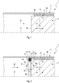
- Fig. 1 to 4 includes an exhaust aftertreatment device 1, which may be, for example, a catalyst or a particulate filter, a tubular housing 2, in which at least two ceramic substrate body, namely a first substrate body 3 and a second substrate body 4 are arranged.
- the two substrate body 3, 4 are arranged with respect to an axial direction 5, which is indicated in the figures by a double arrow, one behind the other.
- the axial direction 5 extends parallel to a longitudinal central axis 6 of the housing 2.
- the exhaust gas aftertreatment device 1 is intended for installation in an exhaust system of an internal combustion engine, preferably a motor vehicle, not shown here.
- an exhaust gas flow which flows through the housing 2 in a flow direction 7, occurs in the housing 2.
- the flow direction 7 is indicated in the figures by an arrow.
- the first substrate body 3 is arranged upstream of the second substrate body 4.
- the first substrate body 3 is mounted in the housing 2 by means of a first bearing mat 8 which, for this purpose, envelops the first substrate body 3 in the circumferential direction and is radially prestressed or pressed between the first substrate body 3 and the housing 2.
- first bearing mat 8 directly on an outer side 9 of the first substrate body 3 and directly to a Lying inside 10 of the housing 2.
- the second substrate body 4 is mounted with a second bearing mat 11 in the housing 2.
- the second bearing mat 11 surrounds the second substrate body 4 in the circumferential direction and is radially pressed or prestressed between the second substrate body 4 and the housing 2.
- the second bearing mat 11 can rest directly on an outer side 12 of the second substrate body 4 and directly on the inner side 10 of the housing 2.
- the exhaust gas aftertreatment device 1 also contains in the housing 2 an axial support 13, which has a support ring 14 and an annular support element 15, which is held by or on the support ring 14.
- the axial support 13 is fastened to the housing 2 by means of at least one welded connection 16.
- the first substrate body 3 is axially supported on the support element 15.
- more than two substrate bodies 3, 4 may also be arranged in the housing 2. It is also conceivable, in an embodiment which contains two or more substrate bodies 3, 4 in the housing 2, to provide two or more than two axial supports 13 in order to axially support the second substrate body 4, and in particular also each further substrate body, on the housing 2.
- each substrate body 3, 4 is assigned in each case only a single axial support 13, which is arranged at the respective substrate body 3, 4 at its outlet side or downstream side.
- Fig. 1 to 4 indicates the flow direction 7 to the left.
- the axial exit side of the respective substrate body 3, 4 is located on the left and is denoted by 26 in the substrate body 3 shown on the right.
- the respective substrate body 3, 4 is at its outlet-side end face 26 with a predetermined bias to the associated axial support 13, so even if no flow through the exhaust aftertreatment device 1 takes place.
- the support ring 14 has an interruption 17 in the circumferential direction, whereby the support ring 14 has a certain elasticity in the radial direction.
- the support element 15 is preferably configured in the circumferential direction without interruption.
- the support element 15 is formed by a wire mesh.
- the support ring 14 has in a cross-section containing the longitudinal central axis 6 a U-profile 18, which has a radially outer outer leg 19, a radially inner inner leg 20 and a base 21.
- the base 21 connects the outer leg 19 with the inner leg 20.
- Outer leg 19 and inner leg 20 form a radial positioning of the support member 15 on the support ring 14.
- the base 21 forms an axial positioning of the support member 15 on the support ring 14.
- the outer leg 19 axially over the inner leg 20 via.
- the outer leg 19 forms a fixing region 22 of the support ring 13, via which the support ring 13 is attached to the housing 2.
- the respective, aforementioned weld 16 is formed on or in this fixing region 22.
- the rest of the U-profile 18 then forms a holding region 23 of the support ring 14, which ultimately holds the support element 15 or fixes it on the support ring 14.
- the fixing region 22 protrudes axially into a radial gap 24, which is formed radially between the housing 2 and the first substrate body 3.
- a radial gap 24 is formed radially between the housing 2 and the first substrate body 3.
- the respective weld 16 is arranged in the region of this radial gap 24, the respective weld 16 is arranged.
- This edge 25 is axially offset relative to an axial end face 26 of the first substrate body 3 facing the axial support 13, such that the edge 25 of the first bearing mat 8 axially projects the aforementioned radial gap 24 limited.
- the housing 2 is unperforated, in particular in the area of the axial support 13.
- the respective welded connection 16 thus extends through the housing 2 into the support ring 14.
- the axial support 13 is inserted into the housing 2, also in the insertion direction 27. Further, the axial support 13 in the housing 2 is positioned axially so that it via the support member 15, a predetermined axial force 28 on the first substrate body 3 transmits.
- the axial force 28 is indicated by an arrow. Accordingly, the axial support 13 is first inserted so far into the housing 2 until the support member 15 contacts the first substrate body 3 at its end face 26. Further, then the axial force 28 is constructed, wherein the support member 15 is elastically compressed. The axial force 28 is smaller than the axial holding force with which the first bearing mat 8 axially positions the first substrate body 3 in the housing 2.
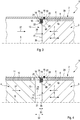
- Fig. 3 is now fixed in a third step of the method, the axial support 13 on the housing 2, in the axially biased positioning of the second step.
- the support ring 14 is welded to the housing 2.
- the at least one welded connection 16 is produced.
- the welded joint 16 is located on the outer leg 19
- the welded joint 16 is located in a region of the support ring 14 which is located outside the support element 15.
- the welding for fixing the Axialabstützung 13 on the housing 2 is performed by an outer side 29 of the housing 2, so that the respective weld 16 is guided through the housing 2 therethrough.
- the welding can be realized with a laser sweep welding process.
- the welds 16 are then circumferentially extending welds, wherein a plurality of such welds are distributed in the circumferential direction and spaced from each other.
- Such a laser welding method can be implemented through the housing 2, so that the housing 2 can be unperforated in the region of the welded connection.
- the welding of the support ring 14 on the housing 2 can also be realized so that the support ring 14 is pressed radially against the housing 2 before welding and welded in this pressed state with the housing 2. Due to the interruption 17, the support ring 14 in the radial direction has a certain elasticity, whereby it can be pressed particularly easily radially against the housing 2.
- the second substrate body 4 can be axially inserted into the housing 2 and stored therein by means of the second bearing mat 11.
- the second substrate body 4 is also inserted into the housing 2 in the insertion direction 27. Accordingly, become the two substrate body 3, 4 and the Axialabstützung 13 introduced through the same, not shown here axial opening of the housing 2 in the housing 2.
- An axial dimension 30 of the axial support 13, which has the axial support 13 within an axial gap 31 formed axially between the two substrate bodies 3, 4, is smaller than an axial gap width 32 of this axial gap 31.
- the gap width 32 is approximately 50%. greater than the axial dimension 30 of the axial support 13 within the axial gap 31.
Landscapes
- Engineering & Computer Science (AREA)
- Chemical & Material Sciences (AREA)
- Chemical Kinetics & Catalysis (AREA)
- Mechanical Engineering (AREA)
- Combustion & Propulsion (AREA)
- General Engineering & Computer Science (AREA)
- Health & Medical Sciences (AREA)
- Toxicology (AREA)
- Ceramic Engineering (AREA)
- Exhaust Gas After Treatment (AREA)
Description
- Die vorliegende Erfindung betrifft ein Verfahren zum Herstellen einer Abgasnachbehandlungseinrichtung. Die Erfindung betrifft außerdem eine nach diesem Verfahren hergestellte Abgasnachbehandlungseinrichtung.
- Abgasnachbehandlungseinrichtungen arbeiten häufig mit keramischen Substratkörpern, wie zum Beispiel Katalysatoren und Partikelfilter. Bei Katalysatoren können die Substratkörper je nach Reinigungsauftrag katalytisch aktiv beschichtet sein, bspw. um einen Oxydationskatalysator oder einen DeNox-Katalysator oder einen Drei-Wege-Katalysator oder einen Hydrolyse-Katalysator oder einen Ammoniak-Sperr-Katalysator zu bilden. Die Substratkörper sind in der Regel aus einem Stück materialeinheitlich, also monolithisch hergestellt, so dass sie jeweils einen Monolithen bilden. Je nach Reinigungsauftrag können auch zwei oder mehr keramische Substratkörper hintereinander durchströmt werden. Ferner kann es zur Effizienzsteigerung möglich sein, zwei oder mehr Substratkörper hintereinander anzuordnen. Auch bei einem Partikelfilter können zwei oder mehr Substratkörper hintereinander angeordnet sein, die sich bspw. durch unterschiedliche Porengrößen voneinander unterscheiden. Auch können Substratkörper mit verschiedenen Reinigungsaufträgen, also insbesondere mit unterschiedlichen katalytischen Beschichtungen, in einem gemeinsamen Gehäuse hintereinander angeordnet sein.
- Zur Realisierung einer kompakten Bauweise kann eine solche Abgasnachbehandlungseinrichtung ein rohrförmiges Gehäuse aufweisen, in dem entweder genau ein keramischer Substratkörper zur Abgasnachbehandlung angeordnet ist oder zumindest zwei keramische Substratkörper zur Abgasnachbehandlung hintereinander angeordnet sind. Üblicherweise erfolgt eine Lagerung derartiger keramischer Substratkörper in einem metallischen Gehäuse mit Hilfe von Lagermatten. Hierbei werden die Lagermatten radial komprimiert. Das Einsetzen der Substratkörper mit Lagermatte in das Gehäuse wird üblicherweise als "Canning" bezeichnet. Von Interesse ist hierbei ein axiales Canning, bei dem der jeweilige Substratkörper mit der Lagermatte axial in das rohrförmige Gehäuse eingeführt wird.
- Zur axialen Lagesicherung des Substratkörpers innerhalb des Gehäuses ist es grundsätzlich möglich, am Gehäuse eine Axialabstützung vorzusehen, an der sich der jeweilige Substratkörper axial abstützen kann. Zweckmäßig ist eine derartige Axialabstützung an der Austrittsseite oder Abströmseite des jeweiligen Substratkörpers angeordnet. Sofern bei einer Abgasnachbehandlungseinrichtung wenigstens zwei Substratkörper im Gehäuse hintereinander angeordnet sind, besteht der Wunsch, den stromauf angeordneten Substratkörper mittels einer derartigen Axialabstützung am Gehäuse abzustützen, um eine Axialverschiebung des zuerst durchströmten Substrats, die zu einer Kollision mit dem stromab angeordneten Substratkörper und somit zu einer Beschädigungsgefahr für beide Substrate führen kann, zu verhindern. Hierdurch erschwert sich die Montage bzw. die Herstellung der Abgasnachbehandlungseinrichtung. Beispielsweise muss bei einem Gehäuse, das eine solche Axialabstützung enthält, der stromauf liegende Substratkörper von einer Einlassseite des Gehäuses in das Gehäuse eingesetzt werden, während der stromab liegende Substratkörper durch eine Auslassseite des Gehäuses in das Gehäuse eingesetzt werden muss, damit anschließend die Axialabstützung axial zwischen den beiden Substratkörpern angeordnet ist. Je nach Canning-Verfahren muss hierzu das Gehäuse in einer entsprechenden Canning-Einrichtung gewendet werden. Bei einer Abgasnachbehandlungseinrichtung, die nur einen einzigen Substratkörper enthält, ist ebenfalls eine Axialabstützung zum Schutz vor einer Kollision des Substratkörpers mit dem Gehäuse erwünscht, wobei sich bei der Herstellung ähnliche Probleme zeigen.
- Aus der
US 4,347,219 A ist ein Verfahren zum Herstellen einer Abgasnachbehandlungseinrichtung bekannt, wobei ein Substratkörper in ein Gehäuse eingeführt und mit Hilfe einer Lagermatte umhüllt sowie radial vorgespannt wird. Zudem wird ein von einem Tragring gehaltenes Stützelement in das Gehäuse eingeführt, gegen den Substratkörper vorgespannt und am Gehäuse verschweißt. - Die
US 4,581,206 A1 zeigt eine Abgasnachbehandlungseinrichtung mit einem Gehäuse und zwei darin angeordneten Substratkörpem, die axial in das Gehäuse eingeführt und mit Hilfe von Axialelementen axial im Gehäuse gehalten sind. Zwischen den Substratkörpern ist dabei eine axial verschiebbare Mittelplatte angeordnet. - In der
EP 2 101 046 A2 ist eine Abgasnachbehandlungseinrichtung mit einem Gehäuse gezeigt, in dem ein Substratkörper angeordnet und axial vom Gehäuse beabstandet ist. - Die vorliegende Erfindung beschäftigt sich mit dem Problem, für eine derartige Abgasnachbehandlungseinrichtung bzw. für ein zugehöriges Herstellungsverfahren eine verbesserte oder zumindest eine andere Ausführungsform anzugeben, die sich insbesondere durch eine reduzierte Beschädigungsgefahr für den jeweiligen Substratkörper sowie optional durch eine vereinfachte Herstellung auszeichnet.
- Dieses Problem wird erfindungsgemäß durch die Gegenstände der unabhängigen Ansprüche gelöst. Vorteilhafte Ausführungsformen sind Gegenstand der abhängigen Ansprüche.
- Die Erfindung beruht auf dem allgemeinen Gedanken, das Canning so durchzuführen, dass zunächst ein Substratkörper mit einer Lagermatte in das Gehäuse eingeführt wird, dass anschließend eine Axialabstützung in das Gehäuse eingeführt und in vorbestimmter Weise zur axialen Abstützung des ersten Substratkörpers im Gehäuse positioniert wird und dass schließlich die Axialabstützung in der gewünschten Position und bei gewünschter axialer Vorspannung zwischen Substratkörper und Axialabstützung am Gehäuse fixiert wird. Hierdurch wird die axiale Positionierung des Substratkörpers in einer vorbestimmten Relativlage im Gehäuse verbessert und die Gefahr einer Verschiebung des Substratkörpers im Betrieb der Abgasnachbehandlungseinrichtung reduziert. Da schon eine solche Axialverschiebung zwischen Substratkörper und Gehäuse die Gefahr einer Beschädigung des Substratkörpers mit sich bringt, kann diese vorgespannte Positionierung und Fixierung die Beschädigungsgefahr für den Substratkörper reduzieren.
- Erfindungsgemäß sind zumindest zwei Substratkörper vorgesehen, wobei nach dem Einsetzen eines ersten Substratkörpers mit einer ersten Lagermatte und nach dem Einsetzen, Positionieren und Fixieren der Axialabstützung ein zweiter Substratkörper mit zweiter Lagermatte in das Gehäuse eingeführt wird, derart, dass anschließend die Axialabstützung axial zwischen dem ersten Substratkörper und dem zweiten Substratkörper angeordnet ist. Durch diese Bauweise ist es insbesondere möglich, die drei genannten Komponenten, nämlich die beiden Substratkörper und die Axialabstützung durch dieselbe Axialöffnung des Gehäuses einzuführen, so dass insbesondere ein Wenden des Gehäuses während des Canning-Prozesses vermieden werden kann.
- Ferner kann optional vorgesehen sein, auch für den zweiten, und insbesondere auch für jeden weiteren Substratkörper, eine solche Axialsicherung vorzusehen, die positioniert und unter der jeweils gewünschten Vorspannung am Gehäuse fixiert wird. Dabei ist bei unterschiedlichen Substratköpern die Einstellung unterschiedlicher axialer Vorspannungen denkbar.
- Bevorzugt erfolgt die Montage derart, dass der jeweilige Substratkörper axial nur einseitig, nämlich ausschließlich austrittsseitig bzw. abströmseitig an einer solchen Axialsicherung axial abgestützt ist, und zwar mit der jeweils vorbestimmten axialen Vorspannung.
- Die jeweilige Axialabstützung ist vorzugsweise mittels eines Tragrings und eines vom Tragring gehaltenen, ringförmigen Stützelements gebildet. Vorzugsweise kann die Axialabstützung im Gehäuse so positioniert werden, dass sie über das Stützelement eine vorbestimmte Axialkraft auf den zuvor in das Gehäuse eingesetzten ersten Substratkörper überträgt. Beispielsweise kann hierzu beim Einsetzen der Axialabstützung die beim Andrücken der Axialabstützung gegen den ersten Substratkörper auftretenden Axialkraft gemessen und auf einen vorbestimmten Wert eingestellt werden. Besonders vorteilhaft ist dann eine Weiterbildung des Verfahrens, bei dem die Axialabstützung bei dieser axial vorgespannten Positionierung am Gehäuse fixiert wird. Beispielsweise kann hierzu der Tragring mit dem Gehäuse verschweißt werden. Durch diese Maßnahme lässt sich die eingestellte, vorbestimmte Axialkraft zwischen axialer Abstützung und erstem Substratkörper quasi einfrieren. Hierdurch wird eine axial vorgespannte Montage des ersten Substratkörpers an der Axialabstützung realisiert, obwohl die Axialabstützung erst nach dem ersten Substratkörper in das Gehäuse eingesetzt wird. Eine axial vorgespannte Montage ist vorteilhaft, da dadurch die Gefahr einer Axialverschiebung des stromaufliegenden Substrats reduziert ist.
- Die hierzu erforderliche Canning-Einrichtung umfasst somit eine Positioniereinrichtung, mit deren Hilfe die Axialabstützung in das Gehäuse einbringbar und mit der vorbestimmten Axialkraft am ersten Substrat abstützbar ist. Hierzu kann die Positioniereinrichtung mit einer Axialkraftmesseinrichtung ausgestattet sein. Ferner ist diese Positioniereinrichtung zweckmäßig so ausgestaltet, dass sie die Axialabstützung auch während des jeweiligen Schweißvorgangs mit der gewünschten Vorspannung relativ zum Gehäuse positionieren kann.
- Entsprechend einer vorteilhaften Weiterbildung des Verfahrens kann der Tragring vor dem Verschweißen radial gegen das Gehäuse angedrückt und in diesem angedrückten Zustand mit dem Gehäuse verschweißt werden. Durch diese Maßnahme wird der Tragring in der Radialrichtung quasi spiel- und spaltfrei am Gehäuse fixiert, wodurch eines besonders effiziente und haltbare Schweißverbindung realisierbar ist. Die zugehörige Positioniereinrichtung ist dann insbesondere zum Aufweiten des Tragrings ausgestaltet, so dass sie den Tragring für den Schweißvorgang radial gegen das Gehäuse andrücken kann.
- Gemäß einer Weiterbildung kann der Tragring in der Umfangsrichtung eine Unterbrechung aufweisen, so dass er zum radialen Andrücken gegen das Gehäuse hinsichtlich seines Durchmessers elastisch verformbar ist. Der in der Umfangsrichtung einfach unterbrochene Tragring vereinfacht das radiale Andrücken des Tragrings an das Gehäuse. Während der Tragring in der Umfangsrichtung unterbrochen ist, kann das Stützelement in der Umfangsrichtung geschlossen bzw. unterbrechungsfrei ausgestaltet sein. Das Stützelement besitzt für die axiale Abstützung des ersten Substratkörpers eine gewisse axiale Elastizität. Die axiale Elastizität kann dabei mit einer ausreichenden Elastizität in der Umfangsrichtung einhergehen, so dass das Stützelement der Aufweitung des Tragrings ohne weiteres elastisch folgen kann.
- Gemäß einer anderen Ausführungsform kann der Tragring einen das Stützelement haltenden Haltebereich und einen zum Verschweißen mit dem Gehäuse vorgesehenen Fixierbereich aufweisen. Der Fixierbereich steht zweckmäßig axial über den Haltebereich und das Stützelement über. Beim Positionieren der Axialabstützung im Gehäuse wird der Fixierbereich in einen Radialspalt eingeführt, der radial zwischen dem Gehäuse und dem ersten Substratkörper ausgebildet ist, wobei in diesem Radialspalt der Fixierbereich mit dem Gehäuse verschweißt wird. Die jeweilige Schweißverbindung ist dadurch axial versetzt zum Stützelement. Durch diese Maßnahme ergeben sich innerhalb der Axialabstützung Hebelarme, welche eine bei der Axialkraftübertragung entstehende Biegebelastung der jeweiligen Schweißverbindung reduzieren, so dass die jeweilige Schweißverbindung im Wesentlichen nur Scherkräfte, also parallel zur Längsmittelachse des Gehäuses verlaufende Zugkräfte übertragen muss. Hierdurch erhält die jeweilige Schweißverbindung eine besonders hohe Dauerhaltbarkeit.
- Entsprechend einer vorteilhaften Weiterbildung kann ein der Axialabstützung zugewandter axialer Rand der ersten Lagermatte gegenüber einer der Axialabstützung zugewandten axialen Stirnseite des ersten Substratkörpers axial versetzt angeordnet sein, so dass besagter Rand der ersten Lagermatte den Radialspalt, in den der vorgenannte Fixierbereich axial eingreift, axial begrenzt. Durch diesen axialen Versatz zwischen erster Lagermatte und erstem Substratkörper kann der Fixierbereich des Tragrings ohne Beschädigung der Lagermatte in den Radialspalt eingeführt werden.
- Bei einer anderen Ausführungsform kann das Verschweißen zum Fixieren der Axialabstützung am Gehäuse von einer Außenseite des Gehäuses, radial durch das Gehäuse hindurch durchgeführt werden. Hierdurch vereinfacht sich die Herstellung, da die Axialabstützung mit Hilfe der vorgenannten Positioniereinrichtung an einer Innenseite des Gehäuses auf gewünschte Weise positioniert werden kann, während die Fixierung der Axialabstützung an der Außenseite mittels einer entsprechenden Schweißeinrichtung erfolgt.
- Beispielsweise kann das Verschweißen der Axialabstützung am Gehäuse als Laser-Wobbel-Schweißen durchgeführt werden. Alternativ kann auch ein Punktschweißverfahren zum Einsatz kommen. Beim Laser-Wobbel-Schweißen werden mittels Laserschweißtechnik diskrete, also in ihrer Längsrichtung begrenzte Schweißnähte erzeugt. Die Längsrichtung der Schweißnähte erstreckt sich zweckmäßig in der Umfangsrichtung des Gehäuses. Dementsprechend werden somit mehrere, in der Umfangsrichtung verteilt und zueinander beabstandet angeordnete Schweißnähte erzeugt, um die Axialabstützung am Gehäuse zu fixieren.
- Entsprechend einer vorteilhaften Weiterbildung kann das Gehäuse im Bereich der Axialabstützung ungelocht sein und im ungelochten Zustand mit dem Tragring verschweißt werden. Hierdurch wird die Fixierung der Abstützung am Gehäuse vereinfacht, da vorab keine Öffnungen im Gehäuse angeordnet werden müssen, um bspw. Schweißstellen zu erzeugen. Die Verschweißung erfolgt durch das Gehäuse bzw. durch den Werkstoff des Gehäuses hindurch.
- Gemäß einer anderen vorteilhaften Ausführungsform kann als Stützelement ein Drahtgestrick verwendet werden, das beim axialen Vorspannen der axialen Abstützung elastisch verformt wird. Ein derartiges Drahtgestrick zeichnet sich durch eine dauerhafte Elastizität auch bei hohen Temperaturen aus.
- Gemäß einer anderen vorteilhaften Ausführungsform kann der Tragring mit einem U-Profil ausgestattet sein, das einen Außenschenkel und einen Innenschenkel zum radialen Positionieren des Stützelements sowie eine den Außenschenkel mit dem Innenschenkel verbindende Basis zum axialen Positionieren des Stützelements aufweist. Ein das U-Profil aufweisender Querschnitt des Tragrings liegt dabei in einer die Längsmittelachse des Gehäuses enthaltenden Schnittebene. Das U-Profil erstreckt sich in der Umfangsrichtung des Tragrings. Durch das U-Profil ist das Stützelement sicher am Tragring positioniert.
- Bevorzugt ist eine Ausführungsform, bei welcher der Außenschenkel axial über den Innenschenkel und vorzugsweise auch über das Stützelement übersteht und mit dem Gehäuse verschweißt wird. Insbesondere bildet der Außenschenkel dann den vorstehend genannten Fixierbereich des Tragrings. Die Schweißverbindung erfolgt somit axial versetzt zum Stützelement.
- Axial zwischen dem ersten Substratkörper und dem zweiten Substratkörper ist ein Axialspalt ausgebildet, in dem der Tragring das Stützelement positioniert. Gemäß einer vorteilhaften Ausführungsform kann eine axiale Abmessung der Axialabstützung innerhalb des Axialspalts kleiner sein als eine axiale Spaltbreite des Axialspalts. Hierdurch wird erreicht, dass der zweite Substratkörper von der Axialabstützung, insbesondere vom Tragring der Axialabstützung, axial beabstandet ist. Dabei kann die Spaltbreite maximal 100%, vorzugsweise maximal 50%, größer sein als die axiale Abmessung der Axialabstützung innerhalb des Axialspalts.
- Gemäß einer anderen vorteilhaften Ausführungsform können der erste Substratkörper, die Axialabstützung und der zweite Substratkörper durch dieselbe Axialöffnung des Gehäuses in das Gehäuse eingeführt werden. Hierdurch vereinfacht sich der Canning-Vorgang, da insbesondere ein Wenden des Gehäuses entfällt.
- Eine erfindungsgemäße Abgasnachbehandlungseinrichtung charakterisiert sich dadurch, dass sie gemäß dem vorstehend beschriebenen Verfahren hergestellt ist. Insbesondere kann eine derartige Abgasnachbehandlungseinrichtung daran erkennbar sein, dass auch bei unbenutzter Abgasnachbehandlungseinrichtung bereits eine axiale Vorspannung zwischen der Axialabstützung und dem jeweiligen Substratkörper vorliegt. Ferner kann eine erfindungsgemäße Abgasnachbehandlungseinrichtung, die zwei oder mehr Substratkörper enthält, daran erkennbar sein, dass nur eine der beiden Axialöffnungen dafür geeignet ist, die Substratkörper und die Axialabstützung einzuführen.
- Weitere wichtige Merkmale und Vorteile der Erfindung ergeben sich aus den Unteransprüchen, aus den Zeichnungen und aus der zugehörigen Figurenbeschreibung anhand der Zeichnungen.
- Es versteht sich, dass die vorstehend genannten und die nachstehend noch zu erläuternden Merkmale nicht nur in der jeweils angegebenen Kombination, sondern auch in anderen Kombinationen oder in Alleinstellung verwendbar sind, ohne den Rahmen der vorliegenden Erfindung zu verlassen.
- Bevorzugte Ausführungsbeispiele der Erfindung sind in den Zeichnungen dargestellt und werden in der nachfolgenden Beschreibung näher erläutert, wobei sich gleiche Bezugszeichen auf gleiche oder ähnliche oder funktional gleiche Bauteile beziehen.
- Es zeigen, jeweils schematisch,
- Fig. 1 bis 4
- jeweils einen Axialschnitt einer Abgasnachbehandlungseinrichtung bei verschiedenen Schritten eines Herstellungsverfahrens.
- Entsprechend den
Fig. 1 bis 4 umfasst eine Abgasnachbehandlungseinrichtung 1, bei der es sich bspw. um einen Katalysator oder um ein Partikelfilter handeln kann, ein rohrförmiges Gehäuse 2, in dem zumindest zwei keramische Substratkörper, nämlich ein erster Substratkörper 3 und ein zweiter Substratkörper 4 angeordnet sind. Die beiden Substratkörper 3, 4 sind dabei bezüglich einer Axialrichtung 5, die in den Figuren durch einen Doppelpfeil angedeutet ist, hintereinander angeordnet. Die Axialrichtung 5 erstreckt sich dabei parallel zu einer Längsmittelachse 6 des Gehäuses 2. Die Abgasnachbehandlungseinrichtung 1 ist für einen Einbau in eine hier nicht gezeigte Abgasanlage einer Brennkraftmaschine, vorzugsweise eines Kraftfahrzeugs, vorgesehen. Im Betrieb der Abgasanlage bzw. der Abgasnachbehandlungseinrichtung 1 stellt sich im Gehäuse 2 eine Abgasströmung ein, die in einer Strömungsrichtung 7 durch das Gehäuse 2 strömt. Die Strömungsrichtung 7 ist dabei in den Figuren durch einen Pfeil angedeutet. Bezüglich dieser Strömungsrichtung 7 ist der erste Substratkörper 3 stromauf des zweiten Substratkörpers 4 angeordnet. - Der erste Substratkörper 3 ist im Gehäuse 2 mittels einer ersten Lagermatte 8 gelagert, die hierzu den ersten Substratkörper 3 in der Umfangsrichtung umhüllt und radial zwischen dem ersten Substratkörper 3 und dem Gehäuse 2 vorgespannt bzw. verpresst ist. Dabei kann die erste Lagermatte 8 unmittelbar an einer Außenseite 9 des ersten Substratkörpers 3 und unmittelbar an einer Innenseite 10 des Gehäuses 2 anliegen. Der zweite Substratkörper 4 ist mit einer zweiten Lagermatte 11 im Gehäuse 2 gelagert. Dabei umhüllt die zweite Lagermatte 11 den zweiten Substratkörper 4 in der Umfangsrichtung und ist radial zwischen dem zweiten Substratkörper 4 und dem Gehäuse 2 verpresst bzw. vorgespannt. Dabei kann die zweite Lagermatte 11 unmittelbar an einer Außenseite 12 des zweiten Substratkörpers 4 und unmittelbar an der Innenseite 10 des Gehäuses 2 anliegen.
- Die Abgasnachbehandlungseinrichtung 1 enthält im Gehäuse 2 außerdem eine Axialabstützung 13, die einen Tragring 14 und ein ringförmiges Stützelement 15 aufweist, das vom bzw. am Tragring 14 gehalten ist. Die Axialabstützung 13 ist mittels wenigstens einer Schweißverbindung 16 am Gehäuse 2 befestigt. Der erste Substratkörper 3 ist am Stützelement 15 axial abgestützt. Im Betrieb der Abgasnachbehandlungseinrichtung 1 kann die Durchströmung des ersten Substratkörpers 3 mit Abgas aufgrund des Durchströmungswiderstands des ersten Substratkörpers 3 in der Strömungsrichtung 7 orientierte Schubkräfte erzeugen, die den ersten Substratkörper 3 relativ zum Gehäuse 2 in der Strömungsrichtung 7 antreiben. Diese Axialkräfte können nun vom ersten Substratkörper 3 über das Stützelement 15 auf den Tragring 14 und von diesem auf das Gehäuse 2 übertragen werden.
- In der Abgasnachbehandlungseinrichtung 1 können auch mehr als zwei Substratkörper 3, 4 im Gehäuse 2 angeordnet sein. Ferner ist denkbar, bei einer Ausführungsform, die im Gehäuse 2 zwei oder mehr Substratkörper 3, 4 enthält, zwei oder mehr als zwei Axialabstützungen 13 vorzusehen, um auch den zweiten Substratkörper 4, und insbesondere auch jeden weiteren Substratkörper, axial am Gehäuse 2 abzustützen.
- Zweckmäßig ist eine Ausführungsform, bei der jedem Substratkörper 3, 4 jeweils nur eine einzige Axialabstützung 13 zugeordnet ist, die beim jeweiligen Substratkörper 3, 4 an dessen Austrittsseite bzw. Abströmseite angeordnet ist. In den
Fig. 1 bis 4 weist die Strömungsrichtung 7 nach links. Dementsprechend befindet sich auch die axiale Austrittsseite des jeweiligen Substratkörpers 3, 4 links und ist bei dem rechts dargestellten Substratkörper 3 mit 26 bezeichnet. Bevorzugt liegt der jeweilige Substratkörper 3, 4 an seiner austrittsseitigen Stirnseite 26 mit einer vorbestimmten Vorspannung an der zugehörigen Axialabstützung 13 an, also auch dann, wenn keine Durchströmung der Abgasnachbehandlungseinrichtung 1 erfolgt. - Der Tragring 14 besitzt in der Umfangsrichtung eine Unterbrechung 17, wodurch der Tragring 14 in der Radialrichtung eine gewisse Elastizität besitzt. Im Unterschied dazu ist das Stützelement 15 in der Umfangsrichtung vorzugsweise unterbrechungsfrei ausgestaltet. Beispielsweise ist das Stützelement 15 durch ein Drahtgestrick gebildet.
- Der Tragring 14 besitzt in einem die Längsmittelachse 6 enthaltenden Querschnitt ein U-Profil 18, das einen radial außen liegenden Außenschenkel 19, einen radial innen liegenden Innenschenkel 20 und eine Basis 21 aufweist. Die Basis 21 verbindet den Außenschenkel 19 mit dem Innenschenkel 20. Außenschenkel 19 und Innenschenkel 20 bilden eine radiale Positionierung des Stützelements 15 am Tragring 14. Die Basis 21 bildet eine axiale Positionierung des Stützelements 15 am Tragring 14. Bei der hier gezeigten Ausführungsform steht der Außenschenkel 19 axial über den Innenschenkel 20 über. Hierdurch bildet der Außenschenkel 19 einen Fixierbereich 22 des Tragrings 13, über den der Tragring 13 am Gehäuse 2 befestigt ist. Insbesondere ist die jeweilige, vorgenannte Schweißstelle 16 an bzw. in diesem Fixierbereich 22 ausgebildet. An Fixierbereich 22 anschließend bildet das übrige U-Profil 18 einen Haltebereich 23 des Tragrings 14, der letztlich das Stützelement 15 hält bzw. am Tragring 14 festlegt.
- Der Fixierbereich 22 ragt axial in einen Radialspalt 24 hinein, der radial zwischen dem Gehäuse 2 und dem ersten Substratkörper 3 ausgebildet ist. Im Bereich dieses Radialspalts 24 ist die jeweilige Schweißstelle 16 angeordnet. Die erste Lagermatte 8 besitzt einen der Axialabstützung 13 zugewandten axialen Rand 25. Dieser Rand 25 ist gegenüber einer der Axialabstützung 13 zugewandten axialen Stirnseite 26 des ersten Substratkörpers 3 axial versetzt angeordnet, derart, dass der Rand 25 der ersten Lagermatte 8 den vorgenannten Radialspalt 24 axial begrenzt.
- Ferner ist das Gehäuse 2 insbesondere im Bereich der Axialabstützung 13 ungelocht. Die jeweilige Schweißverbindung 16 erstreckt sich somit durch das Gehäuse 2 hindurch bis in den Tragring 14 hinein.
- Ein Verfahren zum Herstellen der hier vorgestellten Abgasnachbehandlungseinrichtung 1 charakterisiert sich durch folgende Schritte:
- In einem in
Fig. 1 gezeigten ersten Schritt des Verfahrens wird der erste Substratkörper 3 axial in das Gehäuse 2 eingeführt und mittels der ersten Lagermatte 8 im Gehäuse 2 gelagert. Das Einführen des ersten Substratkörpers 3 erfolgt dabei zweckmäßig in einer Einführrichtung 27, die in den Figuren durch einen Pfeil angedeutet ist und die der Strömungsrichtung 7 entgegen gerichtet ist. Das Einführen des ersten Substratkörpers 3 erfolgt derart, dass der erste Substratkörper 3 anschließend eine vorbestimmte Relativlage bezüglich des Gehäuses 2 besitzt. - Entsprechend
Fig. 2 wird in einem zweiten Schritt des Verfahrens die Axialabstützung 13 in das Gehäuse 2 eingeführt, und zwar ebenfalls in der Einführrichtung 27. Ferner wird die Axialabstützung 13 im Gehäuse 2 axial so positioniert, dass sie über das Stützelement 15 eine vorbestimmte Axialkraft 28 auf den ersten Substratkörper 3 überträgt. Die Axialkraft 28 ist dabei durch einen Pfeil angedeutet. Demnach wird die Axialabstützung 13 zunächst soweit in das Gehäuse 2 eingeführt, bis das Stützelement 15 den ersten Substratkörper 3 an dessen Stirnseite 26 berührt. Ferner wird dann die Axialkraft 28 aufgebaut, wobei das Stützelement 15 elastisch komprimiert wird. Die Axialkraft 28 ist dabei kleiner als die axiale Haltekraft, mit der die erste Lagermatte 8 den ersten Substratkörper 3 im Gehäuse 2 axial positioniert. - Gemäß
Fig. 3 wird nun in einem dritten Schritt des Verfahrens die Axialabstützung 13 am Gehäuse 2 fixiert, und zwar in der axial vorgespannten Positionierung des zweiten Schritts. Hierzu wird der Tragring 14 mit dem Gehäuse 2 verschweißt. Hierbei wird die wenigstens eine Schweißverbindung 16 hergestellt. Die Schweißverbindung 16 befindet sich dabei am Außenschenkel 19 bzw. im Fixierbereich 22. Jedenfalls befindet sich die Schweißverbindung 16 in einem Bereich des Tragrings 14, der sich außerhalb des Stützelements 15 befindet. Das Verschweißen zum Fixieren der Axialabstützung 13 am Gehäuse 2 wird dabei von einer Außenseite 29 des Gehäuses 2 durchgeführt, so dass die jeweilige Schweißstelle 16 durch das Gehäuse 2 hindurch geführt ist. Das Verschweißen kann dabei mit einem Laser-Wobbel-Schweißverfahren realisiert werden. Die Schweißstellen 16 sind dann sich in der Umfangsrichtung erstreckende Schweißnähte, wobei mehrere derartige Schweißnähte in der Umfangsrichtung verteilt und zueinander beabstandet angeordnet sind. Ein derartiges Laser-Schweiß-Verfahren kann durch das Gehäuse 2 hindurch realisiert werden, so dass das Gehäuse 2 im Bereich der Schweißverbindung ungelocht sein kann. - Da der Tragring 14 bevorzugt in angedrücktem Zustand unter der Axialkraft 28 am Gehäuse 2 fixiert wird, liegt diese Axialkraft 28 auch nach dem Anbringen der Schweißverbindungen 16 vor.
- Das Verschweißen des Tragring 14 am Gehäuse 2 kann ferner auch so realisiert werden, dass der Tragring 14 vor dem Verschweißen radial gegen das Gehäuse 2 angedrückt und in diesem angedrückten Zustand mit dem Gehäuse 2 verschweißt wird. Durch die Unterbrechung 17 besitzt der Tragring 14 in der Radialrichtung eine gewisse Elastizität, wodurch er besonders einfach radial gegen das Gehäuse 2 angedrückt werden kann.
- Gemäß
Fig. 4 kann nun in einem vierten Schritt des Verfahrens der zweite Substratkörper 4 axial in das Gehäuse 2 eingeführt und darin mittels der zweiten Lagermatte 11 gelagert werden. Auch der zweite Substratkörper 4 wird dabei in der Einführrichtung 27 in das Gehäuse 2 eingeführt. Dementsprechend werden die beiden Substratkörper 3, 4 und die Axialabstützung 13 durch dieselbe, hier nicht gezeigte Axialöffnung des Gehäuses 2 in das Gehäuse 2 eingeführt. - Wie sich nun
Fig. 4 entnehmen lässt, ist eine axiale Abmessung 30 der Axialabstützung 13, welche die Axialabstützung 13 innerhalb eines axial zwischen den beiden Substratkörpern 3, 4 ausgebildeten Axialspalts 31 aufweist, kleiner als eine axiale Spaltbreite 32 dieses Axialspalts 31. Im Beispiel ist die Spaltbreite 32 etwa 50% größer als die axiale Abmessung 30 der Axialabstützung 13 innerhalb des Axialspalts 31.
Claims (14)
- Verfahren zum Herstellen einer Abgasnachbehandlungseinrichtung (1), die in einem rohrförmigen Gehäuse (2) wenigstens einen keramischen Substratkörper (3, 4) zur Abgasnachbehandlung aufweist,- bei dem ein erster Substratkörper (3) axial in das Gehäuse (2) eingeführt und mittels einer ersten Lagermatte (8) im Gehäuse (2) gelagert wird, wobei die erste Lagermatte (8) den ersten Substratkörper (3) in der Umfangsrichtung umhüllt und radial zwischen dem ersten Substratkörper (3) und dem Gehäuse (2) vorgespannt ist,- bei dem eine Axialabstützung (13), die einen Tragring (14) und ein vom Tragring (14) gehaltenes, ringförmiges Stützelement (15) aufweist, axial in das Gehäuse (2) eingeführt und darin so positioniert wird, dass sie über das Stützelement (15) eine vorbestimmte Axialkraft (28) auf den ersten Substratkörper (3) überträgt,- bei dem die Axialabstützung (13) bei dieser axial vorgespannten Positionierung am Gehäuse (2) fixiert wird, indem der Tragring (14) mit dem Gehäuse (2) verschweißt wird,dadurch gekennzeichnet,
dass ein zweiter Substratkörper (4) axial in das Gehäuse (2) eingeführt und mittels einer zweiten Lagermatte (11) im Gehäuse (2) gelagert wird, wobei die zweite Lagermatte (11) den zweiten Substratkörper (4) in der Umfangsrichtung umhüllt und radial zwischen dem zweiten Substratkörper (4) und dem Gehäuse (2) vorgespannt ist, und wobei axial zwischen dem ersten Substratkörper (3) und dem zweiten Substratkörper (4) ein Axialspalt (31) ausgebildet wird, in dem der Tragring (14) das Stützelement (15) positioniert. - Verfahren nach Anspruch 1,
dadurch gekennzeichnet,
dass der Tragring (14) vor dem Verschweißen radial gegen das Gehäuse (2) angedrückt und in diesem angedrückten Zustand mit dem Gehäuse (2) verschweißt wird. - Verfahren nach Anspruch 2,
dadurch gekennzeichnet,
dass ein solcher Tragring (14) mit einer Unterbrechung (17) in der Umfangsrichtung verwendet wird. - Verfahren nach einem der Ansprüche 1 bis 3,
dadurch gekennzeichnet,
dass der Tragring (14) einen das Stützelement (15) haltenden Haltebereich (23) und einen zum Verschweißen mit dem Gehäuse (2) vorgesehenen Fixierbereich (22) aufweist, wobei der Fixierbereich (22) beim Positionieren der Axialabstützung (13) im Gehäuse (2) axial in einen Ringspalt (24) eingeführt wird, der radial zwischen dem Gehäuse (2) und dem ersten Substratkörper (3) ausgebildet ist, und in diesem Radialspalt (24) mit dem Gehäuse (2) verschweißt wird. - Verfahren nach Anspruch 4,
dadurch gekennzeichnet,
dass ein der Axialabstützung (13) zugewandter axialer Rand (25) der ersten Lagermatte (8) gegenüber einer der Axialabstützung (13) zugewandten axialen Stirnseite (26) des ersten Substratkörpers (3) axial versetzt angeordnet ist, so dass besagter Rand (25) den Radialspalt (24), in den der Fixierbereich (22) axial eingreift, axial begrenzt. - Verfahren nach einem der Ansprüche 1 bis 5,
dadurch gekennzeichnet,
dass das Verschweißen zum Fixieren der Axialabstützung (13) am Gehäuse (2) von einer Außenseite (29) des Gehäuses (2), radial durch das Gehäuse (2) hindurch durchgeführt wird. - Verfahren nach einem der Ansprüche 1 bis 6,
dadurch gekennzeichnet,
dass das Verschweißen als Laser-Wobbel-Schweißen durchgeführt wird. - Verfahren nach Anspruch 6 oder 7,
dadurch gekennzeichnet,
dass das Gehäuse (2) im Bereich der Axialabstützung (13) ungelocht ist und im ungelochten Zustand mit dem Tragring (14) verschweißt wird. - Verfahren nach einem der Ansprüche 1 bis 8,
dadurch gekennzeichnet,
dass als Stützelement (15) ein Drahtgestrick verwendet wird, das beim axialen Vorspannen der Axialabstützung (13) elastisch verformt wird. - Verfahren nach einem der Ansprüche 1 bis 9,
dadurch gekennzeichnet,
dass der Tragring (14) mit einem U-Profil (18) ausgestattet wird, das einen Außenschenkel (19) und einen Innenschenkel (20) zum radialen Positionieren des Stützelements (15) und eine den Außenschenkel (19) mit dem Innenschenkel (20) verbindende Basis (21) zum axialen Positionieren des Stützelements (15) aufweist, wobei der Außenschenkel (19) axial über den Innenschenkel (20) vorsteht und mit dem Gehäuse (2) verschweißt wird. - Verfahren nach einem der Ansprüche 1 bis 10,
dadurch gekennzeichnet,
dass eine axiale Abmessung (30) der Axialabstützung (13) innerhalb des Axialspalts (31) kleiner ist als eine axiale Spaltbreite (32) des Axialspalts (31), wobei die Spaltbreite (32) maximal 100%, vorzugsweise maximal 50%, größer ist als die axiale Abmessung (30) der Axialabstützung (13) innerhalb des Axialspalts (31). - Verfahren nach einem der Ansprüche 1 bis 11,
dadurch gekennzeichnet,
dass der erste Substratkörper (3), die Axialabstützung (13) und der zweite Substratkörper (4) durch dieselbe Axialöffnung des Gehäuses (2) in das Gehäuse (2) eingeführt werden. - Verfahren nach einem der Ansprüche 1 bis 12,
dadurch gekennzeichnet,
dass der jeweilige Substratkörper (3, 4) ausschließlich an seiner Austrittsseite (26) an einer solchen Axialabstützung (13) axial abgestützt wird. - Abgasnachbehandlungseinrichtung hergestellt mit einem Verfahren nach einem der Ansprüche 1 bis 13.
Applications Claiming Priority (1)
| Application Number | Priority Date | Filing Date | Title |
|---|---|---|---|
| DE102014203495.7A DE102014203495A1 (de) | 2014-02-26 | 2014-02-26 | Abgasnachbehandlungseinrichtung und zugehöriges Herstellverfahren |
Publications (2)
| Publication Number | Publication Date |
|---|---|
| EP2913495A1 EP2913495A1 (de) | 2015-09-02 |
| EP2913495B1 true EP2913495B1 (de) | 2017-08-09 |
Family
ID=52021061
Family Applications (1)
| Application Number | Title | Priority Date | Filing Date |
|---|---|---|---|
| EP14197087.1A Active EP2913495B1 (de) | 2014-02-26 | 2014-12-10 | Verfahren zum Herstellen einer Abgasnachbehandlungseinrichtung und entsprechende Abgasnachbehandlungseinrichtung |
Country Status (5)
| Country | Link |
|---|---|
| US (1) | US9650931B2 (de) |
| EP (1) | EP2913495B1 (de) |
| JP (1) | JP6063970B2 (de) |
| CN (1) | CN104863673B (de) |
| DE (1) | DE102014203495A1 (de) |
Families Citing this family (4)
| Publication number | Priority date | Publication date | Assignee | Title |
|---|---|---|---|---|
| DE102017107893A1 (de) * | 2017-04-12 | 2018-10-18 | Dr. Ing. H.C. F. Porsche Aktiengesellschaft | Verfahren zur Herstellung einer einen Partikelfilter aufweisenden Abgasanlage eines Ottomotors sowie Abgasanlage eines Ottomotors |
| US11319847B2 (en) * | 2018-09-19 | 2022-05-03 | Tenneco Automotive Operating Company Inc. | Exhaust device with noise suppression system |
| EP4047192B1 (de) * | 2021-02-18 | 2023-11-22 | Purem GmbH | Abstützbaugruppe zur abstützung eines in einem gehäuse aufgenommenen abgasbehandlungselements |
| NL2034346B1 (en) * | 2023-03-15 | 2024-09-26 | Daf Trucks Nv | An exhaust after treatment assembly. |
Family Cites Families (17)
| Publication number | Priority date | Publication date | Assignee | Title |
|---|---|---|---|---|
| DE2213540C3 (de) * | 1972-03-21 | 1974-06-12 | Zeuna-Staerker Kg, 8900 Augsburg | Katalysatorkörper zur Reinigung der Abgase von Brennkraftmaschinen und Verfahren zur Herstellung dieses Katalysators |
| DE2261663C2 (de) * | 1972-12-16 | 1983-07-14 | Fa. J. Eberspächer, 7300 Esslingen | Elastische Lagerung für keramische Katalysatorträger |
| IN141845B (de) | 1973-09-26 | 1977-04-23 | Engelhard Min & Chem | |
| US4347219A (en) * | 1979-12-29 | 1982-08-31 | Honda Giken Kogyo Kabushiki Kaisha | Catalytic converter for exhaust-gas cleaning use and method of assembling same |
| JPS59215914A (ja) * | 1983-05-24 | 1984-12-05 | Honda Motor Co Ltd | 二段触媒コンバ−タ |
| JPS6390612A (ja) * | 1986-10-02 | 1988-04-21 | Mazda Motor Corp | 触媒コンバ−タ |
| JPH0636268Y2 (ja) * | 1989-03-27 | 1994-09-21 | 日本碍子株式会社 | 触媒コンバータ |
| US5068637A (en) * | 1990-02-08 | 1991-11-26 | General Electric Company | Plate-like metal element for electrical resistor grid assembly |
| JP2591675Y2 (ja) * | 1993-03-22 | 1999-03-10 | カルソニック株式会社 | マニホールド触媒コンバータの触媒担体支持構造 |
| JPH06264734A (ja) * | 1993-03-11 | 1994-09-20 | Calsonic Corp | セラミックス製触媒コンバータおよびその製造方法 |
| JP3206779B2 (ja) * | 1993-03-24 | 2001-09-10 | カルソニックカンセイ株式会社 | 触媒コンバータの製造方法 |
| US5555621A (en) * | 1993-03-11 | 1996-09-17 | Calsonic Corporation | Method of producing a catalytic converter |
| US20070011874A1 (en) * | 2005-07-18 | 2007-01-18 | Myers Stephen J | Exhaust treatment devices and methods of making the same |
| US20080241007A1 (en) * | 2007-04-02 | 2008-10-02 | Delphi Technologies, Inc. | Catalytic converter with inner sheath and method for making the same |
| WO2009113159A1 (ja) * | 2008-03-11 | 2009-09-17 | イビデン株式会社 | 排ガス浄化装置 |
| DE102008016236A1 (de) | 2008-03-27 | 2009-10-01 | J. Eberspächer GmbH & Co. KG | Abgasbehandlungseinrichtung |
| ES2375880T3 (es) * | 2008-07-30 | 2012-03-07 | Ipg Photonics Corporation | Útil de soldadura por l�?ser con un l�?ser de fibra. |
-
2014
- 2014-02-26 DE DE102014203495.7A patent/DE102014203495A1/de not_active Withdrawn
- 2014-12-10 EP EP14197087.1A patent/EP2913495B1/de active Active
-
2015
- 2015-01-28 CN CN201510043910.2A patent/CN104863673B/zh active Active
- 2015-01-29 JP JP2015015279A patent/JP6063970B2/ja active Active
- 2015-02-25 US US14/631,271 patent/US9650931B2/en active Active
Non-Patent Citations (1)
| Title |
|---|
| None * |
Also Published As
| Publication number | Publication date |
|---|---|
| DE102014203495A1 (de) | 2015-08-27 |
| JP6063970B2 (ja) | 2017-01-18 |
| CN104863673A (zh) | 2015-08-26 |
| CN104863673B (zh) | 2018-04-27 |
| US20150240684A1 (en) | 2015-08-27 |
| US9650931B2 (en) | 2017-05-16 |
| JP2015161302A (ja) | 2015-09-07 |
| EP2913495A1 (de) | 2015-09-02 |
Similar Documents
| Publication | Publication Date | Title |
|---|---|---|
| EP1830042B1 (de) | Statischer Mischer und Abgasbehandlungseinrichtung | |
| EP2261475B1 (de) | Abgasreinigungseinrichtung | |
| EP2420656B1 (de) | Abgasreinigungsvorrichtung, Abgasanlage, Ausbauverfahren | |
| EP2324218B1 (de) | Verfahren zum herstellen einer abgas führenden vorrichtung sowie werkzeug hierfür | |
| EP1437490B1 (de) | Abgasbehandlungseinrichtung | |
| EP2075425A1 (de) | Schiebesitz sowie Rohranordnung und Abgasbehandlungseinrichtung | |
| EP2913495B1 (de) | Verfahren zum Herstellen einer Abgasnachbehandlungseinrichtung und entsprechende Abgasnachbehandlungseinrichtung | |
| WO2003074925A1 (de) | Verfahren zum herstellen eines wabenkörpers mit einem flanschstück für einen messfühler und entsprechender wabenkörper | |
| EP2216525B1 (de) | Abgasreinigungseinrichtung, Abgasanlage und Schellenverbindung | |
| DE102006036914A1 (de) | Abgasreinigungseinrichtung | |
| EP3045694B1 (de) | Stützring für ein abgasführungssystem | |
| EP1715155A2 (de) | Abgasanlage und zugehörige Abgasbehandlungsvorrichtung | |
| EP2799681A1 (de) | Abgasanlagenkomponente | |
| EP1860291B1 (de) | Schalldämpferboden | |
| EP1769143B1 (de) | Abgasreinigungsvorrichtung für kraftfahrzeuge | |
| DE102004056804B4 (de) | Katalysator und/oder Partikelfilter sowie zugehöriges Herstellungsverfahren und zugehörige Lagermatte | |
| DE102007026810A1 (de) | Herstellungsverfahren für Abgasbehandlungseinrichtungen, wie z.B. Abgaskatalysatoren und Partikelfilter | |
| DE3922667A1 (de) | Vorrichtung zur katalytischen entgiftung oder dgl. von verbrennungsmotor-abgasen mit doppelwandigem gehaeuse | |
| EP2034150A1 (de) | Verfahren zum Anbringen einer Sonde an einer Abgasbehandlungseinrichtung | |
| WO2009018918A2 (de) | Entkopplungselement für die abgasanlage eines kraftfahrzeugs | |
| DE102005031677B4 (de) | Abgasbehandlungseinrichtung und zugehöriges Herstellungsverfahren | |
| EP2915973B1 (de) | Trichter-Rohr-Anordnung | |
| DE102011016170A1 (de) | Abgas führende Vorrichtung und Verfahren zu ihrer Herstellung | |
| DE10190162B4 (de) | Katalysator-Trägerkörper mit einer Dehnungen erlaubenden Manschette mit Mikrostrukturen | |
| DE102008008352A1 (de) | Bauteilverbindung |
Legal Events
| Date | Code | Title | Description |
|---|---|---|---|
| PUAI | Public reference made under article 153(3) epc to a published international application that has entered the european phase |
Free format text: ORIGINAL CODE: 0009012 |
|
| AK | Designated contracting states |
Kind code of ref document: A1 Designated state(s): AL AT BE BG CH CY CZ DE DK EE ES FI FR GB GR HR HU IE IS IT LI LT LU LV MC MK MT NL NO PL PT RO RS SE SI SK SM TR |
|
| AX | Request for extension of the european patent |
Extension state: BA ME |
|
| 17P | Request for examination filed |
Effective date: 20160121 |
|
| RBV | Designated contracting states (corrected) |
Designated state(s): AL AT BE BG CH CY CZ DE DK EE ES FI FR GB GR HR HU IE IS IT LI LT LU LV MC MK MT NL NO PL PT RO RS SE SI SK SM TR |
|
| 17Q | First examination report despatched |
Effective date: 20160923 |
|
| REG | Reference to a national code |
Ref country code: DE Ref legal event code: R079 Ref document number: 502014004908 Country of ref document: DE Free format text: PREVIOUS MAIN CLASS: F01N0003280000 Ipc: F01N0003180000 |
|
| GRAP | Despatch of communication of intention to grant a patent |
Free format text: ORIGINAL CODE: EPIDOSNIGR1 |
|
| RIC1 | Information provided on ipc code assigned before grant |
Ipc: F01N 13/00 20100101ALI20170208BHEP Ipc: B23K 31/02 20060101ALI20170208BHEP Ipc: F01N 3/20 20060101ALI20170208BHEP Ipc: F01N 3/18 20060101AFI20170208BHEP Ipc: F01N 3/28 20060101ALI20170208BHEP |
|
| INTG | Intention to grant announced |
Effective date: 20170303 |
|
| GRAS | Grant fee paid |
Free format text: ORIGINAL CODE: EPIDOSNIGR3 |
|
| GRAA | (expected) grant |
Free format text: ORIGINAL CODE: 0009210 |
|
| AK | Designated contracting states |
Kind code of ref document: B1 Designated state(s): AL AT BE BG CH CY CZ DE DK EE ES FI FR GB GR HR HU IE IS IT LI LT LU LV MC MK MT NL NO PL PT RO RS SE SI SK SM TR |
|
| REG | Reference to a national code |
Ref country code: GB Ref legal event code: FG4D Free format text: NOT ENGLISH |
|
| REG | Reference to a national code |
Ref country code: CH Ref legal event code: EP Ref country code: AT Ref legal event code: REF Ref document number: 917105 Country of ref document: AT Kind code of ref document: T Effective date: 20170815 |
|
| REG | Reference to a national code |
Ref country code: IE Ref legal event code: FG4D Free format text: LANGUAGE OF EP DOCUMENT: GERMAN |
|
| REG | Reference to a national code |
Ref country code: DE Ref legal event code: R096 Ref document number: 502014004908 Country of ref document: DE |
|
| REG | Reference to a national code |
Ref country code: SE Ref legal event code: TRGR |
|
| REG | Reference to a national code |
Ref country code: NL Ref legal event code: MP Effective date: 20170809 |
|
| REG | Reference to a national code |
Ref country code: FR Ref legal event code: PLFP Year of fee payment: 4 |
|
| REG | Reference to a national code |
Ref country code: LT Ref legal event code: MG4D |
|
| PG25 | Lapsed in a contracting state [announced via postgrant information from national office to epo] |
Ref country code: HR Free format text: LAPSE BECAUSE OF FAILURE TO SUBMIT A TRANSLATION OF THE DESCRIPTION OR TO PAY THE FEE WITHIN THE PRESCRIBED TIME-LIMIT Effective date: 20170809 Ref country code: LT Free format text: LAPSE BECAUSE OF FAILURE TO SUBMIT A TRANSLATION OF THE DESCRIPTION OR TO PAY THE FEE WITHIN THE PRESCRIBED TIME-LIMIT Effective date: 20170809 Ref country code: NL Free format text: LAPSE BECAUSE OF FAILURE TO SUBMIT A TRANSLATION OF THE DESCRIPTION OR TO PAY THE FEE WITHIN THE PRESCRIBED TIME-LIMIT Effective date: 20170809 Ref country code: FI Free format text: LAPSE BECAUSE OF FAILURE TO SUBMIT A TRANSLATION OF THE DESCRIPTION OR TO PAY THE FEE WITHIN THE PRESCRIBED TIME-LIMIT Effective date: 20170809 Ref country code: NO Free format text: LAPSE BECAUSE OF FAILURE TO SUBMIT A TRANSLATION OF THE DESCRIPTION OR TO PAY THE FEE WITHIN THE PRESCRIBED TIME-LIMIT Effective date: 20171109 |
|
| PG25 | Lapsed in a contracting state [announced via postgrant information from national office to epo] |
Ref country code: PL Free format text: LAPSE BECAUSE OF FAILURE TO SUBMIT A TRANSLATION OF THE DESCRIPTION OR TO PAY THE FEE WITHIN THE PRESCRIBED TIME-LIMIT Effective date: 20170809 Ref country code: RS Free format text: LAPSE BECAUSE OF FAILURE TO SUBMIT A TRANSLATION OF THE DESCRIPTION OR TO PAY THE FEE WITHIN THE PRESCRIBED TIME-LIMIT Effective date: 20170809 Ref country code: BG Free format text: LAPSE BECAUSE OF FAILURE TO SUBMIT A TRANSLATION OF THE DESCRIPTION OR TO PAY THE FEE WITHIN THE PRESCRIBED TIME-LIMIT Effective date: 20171109 Ref country code: ES Free format text: LAPSE BECAUSE OF FAILURE TO SUBMIT A TRANSLATION OF THE DESCRIPTION OR TO PAY THE FEE WITHIN THE PRESCRIBED TIME-LIMIT Effective date: 20170809 Ref country code: IS Free format text: LAPSE BECAUSE OF FAILURE TO SUBMIT A TRANSLATION OF THE DESCRIPTION OR TO PAY THE FEE WITHIN THE PRESCRIBED TIME-LIMIT Effective date: 20171209 Ref country code: GR Free format text: LAPSE BECAUSE OF FAILURE TO SUBMIT A TRANSLATION OF THE DESCRIPTION OR TO PAY THE FEE WITHIN THE PRESCRIBED TIME-LIMIT Effective date: 20171110 Ref country code: LV Free format text: LAPSE BECAUSE OF FAILURE TO SUBMIT A TRANSLATION OF THE DESCRIPTION OR TO PAY THE FEE WITHIN THE PRESCRIBED TIME-LIMIT Effective date: 20170809 |
|
| PGFP | Annual fee paid to national office [announced via postgrant information from national office to epo] |
Ref country code: IT Payment date: 20171231 Year of fee payment: 4 |
|
| PG25 | Lapsed in a contracting state [announced via postgrant information from national office to epo] |
Ref country code: CZ Free format text: LAPSE BECAUSE OF FAILURE TO SUBMIT A TRANSLATION OF THE DESCRIPTION OR TO PAY THE FEE WITHIN THE PRESCRIBED TIME-LIMIT Effective date: 20170809 Ref country code: DK Free format text: LAPSE BECAUSE OF FAILURE TO SUBMIT A TRANSLATION OF THE DESCRIPTION OR TO PAY THE FEE WITHIN THE PRESCRIBED TIME-LIMIT Effective date: 20170809 Ref country code: RO Free format text: LAPSE BECAUSE OF FAILURE TO SUBMIT A TRANSLATION OF THE DESCRIPTION OR TO PAY THE FEE WITHIN THE PRESCRIBED TIME-LIMIT Effective date: 20170809 |
|
| REG | Reference to a national code |
Ref country code: DE Ref legal event code: R097 Ref document number: 502014004908 Country of ref document: DE |
|
| PG25 | Lapsed in a contracting state [announced via postgrant information from national office to epo] |
Ref country code: SM Free format text: LAPSE BECAUSE OF FAILURE TO SUBMIT A TRANSLATION OF THE DESCRIPTION OR TO PAY THE FEE WITHIN THE PRESCRIBED TIME-LIMIT Effective date: 20170809 Ref country code: SK Free format text: LAPSE BECAUSE OF FAILURE TO SUBMIT A TRANSLATION OF THE DESCRIPTION OR TO PAY THE FEE WITHIN THE PRESCRIBED TIME-LIMIT Effective date: 20170809 Ref country code: EE Free format text: LAPSE BECAUSE OF FAILURE TO SUBMIT A TRANSLATION OF THE DESCRIPTION OR TO PAY THE FEE WITHIN THE PRESCRIBED TIME-LIMIT Effective date: 20170809 |
|
| PLBE | No opposition filed within time limit |
Free format text: ORIGINAL CODE: 0009261 |
|
| STAA | Information on the status of an ep patent application or granted ep patent |
Free format text: STATUS: NO OPPOSITION FILED WITHIN TIME LIMIT |
|
| 26N | No opposition filed |
Effective date: 20180511 |
|
| REG | Reference to a national code |
Ref country code: CH Ref legal event code: PL |
|
| PG25 | Lapsed in a contracting state [announced via postgrant information from national office to epo] |
Ref country code: SI Free format text: LAPSE BECAUSE OF FAILURE TO SUBMIT A TRANSLATION OF THE DESCRIPTION OR TO PAY THE FEE WITHIN THE PRESCRIBED TIME-LIMIT Effective date: 20170809 |
|
| REG | Reference to a national code |
Ref country code: IE Ref legal event code: MM4A |
|
| PG25 | Lapsed in a contracting state [announced via postgrant information from national office to epo] |
Ref country code: LU Free format text: LAPSE BECAUSE OF NON-PAYMENT OF DUE FEES Effective date: 20171210 Ref country code: MT Free format text: LAPSE BECAUSE OF FAILURE TO SUBMIT A TRANSLATION OF THE DESCRIPTION OR TO PAY THE FEE WITHIN THE PRESCRIBED TIME-LIMIT Effective date: 20170809 |
|
| REG | Reference to a national code |
Ref country code: BE Ref legal event code: MM Effective date: 20171231 |
|
| PG25 | Lapsed in a contracting state [announced via postgrant information from national office to epo] |
Ref country code: IE Free format text: LAPSE BECAUSE OF NON-PAYMENT OF DUE FEES Effective date: 20171210 |
|
| PG25 | Lapsed in a contracting state [announced via postgrant information from national office to epo] |
Ref country code: LI Free format text: LAPSE BECAUSE OF NON-PAYMENT OF DUE FEES Effective date: 20171231 Ref country code: CH Free format text: LAPSE BECAUSE OF NON-PAYMENT OF DUE FEES Effective date: 20171231 Ref country code: BE Free format text: LAPSE BECAUSE OF NON-PAYMENT OF DUE FEES Effective date: 20171231 |
|
| PG25 | Lapsed in a contracting state [announced via postgrant information from national office to epo] |
Ref country code: HU Free format text: LAPSE BECAUSE OF FAILURE TO SUBMIT A TRANSLATION OF THE DESCRIPTION OR TO PAY THE FEE WITHIN THE PRESCRIBED TIME-LIMIT; INVALID AB INITIO Effective date: 20141210 Ref country code: MC Free format text: LAPSE BECAUSE OF FAILURE TO SUBMIT A TRANSLATION OF THE DESCRIPTION OR TO PAY THE FEE WITHIN THE PRESCRIBED TIME-LIMIT Effective date: 20170809 |
|
| PG25 | Lapsed in a contracting state [announced via postgrant information from national office to epo] |
Ref country code: CY Free format text: LAPSE BECAUSE OF FAILURE TO SUBMIT A TRANSLATION OF THE DESCRIPTION OR TO PAY THE FEE WITHIN THE PRESCRIBED TIME-LIMIT Effective date: 20170809 Ref country code: IT Free format text: LAPSE BECAUSE OF NON-PAYMENT OF DUE FEES Effective date: 20181210 |
|
| PG25 | Lapsed in a contracting state [announced via postgrant information from national office to epo] |
Ref country code: MK Free format text: LAPSE BECAUSE OF FAILURE TO SUBMIT A TRANSLATION OF THE DESCRIPTION OR TO PAY THE FEE WITHIN THE PRESCRIBED TIME-LIMIT Effective date: 20170809 |
|
| PG25 | Lapsed in a contracting state [announced via postgrant information from national office to epo] |
Ref country code: TR Free format text: LAPSE BECAUSE OF FAILURE TO SUBMIT A TRANSLATION OF THE DESCRIPTION OR TO PAY THE FEE WITHIN THE PRESCRIBED TIME-LIMIT Effective date: 20170809 |
|
| PG25 | Lapsed in a contracting state [announced via postgrant information from national office to epo] |
Ref country code: PT Free format text: LAPSE BECAUSE OF FAILURE TO SUBMIT A TRANSLATION OF THE DESCRIPTION OR TO PAY THE FEE WITHIN THE PRESCRIBED TIME-LIMIT Effective date: 20170809 |
|
| PG25 | Lapsed in a contracting state [announced via postgrant information from national office to epo] |
Ref country code: AL Free format text: LAPSE BECAUSE OF FAILURE TO SUBMIT A TRANSLATION OF THE DESCRIPTION OR TO PAY THE FEE WITHIN THE PRESCRIBED TIME-LIMIT Effective date: 20170809 |
|
| REG | Reference to a national code |
Ref country code: AT Ref legal event code: MM01 Ref document number: 917105 Country of ref document: AT Kind code of ref document: T Effective date: 20191210 |
|
| PG25 | Lapsed in a contracting state [announced via postgrant information from national office to epo] |
Ref country code: AT Free format text: LAPSE BECAUSE OF NON-PAYMENT OF DUE FEES Effective date: 20191210 |
|
| REG | Reference to a national code |
Ref country code: DE Ref legal event code: R081 Ref document number: 502014004908 Country of ref document: DE Owner name: PUREM GMBH, DE Free format text: FORMER OWNER: EBERSPAECHER EXHAUST TECHNOLOGY GMBH & CO. KG, 66539 NEUNKIRCHEN, DE |
|
| PGFP | Annual fee paid to national office [announced via postgrant information from national office to epo] |
Ref country code: SE Payment date: 20211220 Year of fee payment: 8 |
|
| REG | Reference to a national code |
Ref country code: SE Ref legal event code: EUG |
|
| PG25 | Lapsed in a contracting state [announced via postgrant information from national office to epo] |
Ref country code: SE Free format text: LAPSE BECAUSE OF NON-PAYMENT OF DUE FEES Effective date: 20221211 |
|
| PGFP | Annual fee paid to national office [announced via postgrant information from national office to epo] |
Ref country code: DE Payment date: 20241216 Year of fee payment: 11 |
|
| PGFP | Annual fee paid to national office [announced via postgrant information from national office to epo] |
Ref country code: GB Payment date: 20251218 Year of fee payment: 12 |
|
| PGFP | Annual fee paid to national office [announced via postgrant information from national office to epo] |
Ref country code: FR Payment date: 20251217 Year of fee payment: 12 |