EP2913484A2 - Générateur d'énergie et procédé de couplage de turbine - Google Patents
Générateur d'énergie et procédé de couplage de turbine Download PDFInfo
- Publication number
- EP2913484A2 EP2913484A2 EP15153087.0A EP15153087A EP2913484A2 EP 2913484 A2 EP2913484 A2 EP 2913484A2 EP 15153087 A EP15153087 A EP 15153087A EP 2913484 A2 EP2913484 A2 EP 2913484A2
- Authority
- EP
- European Patent Office
- Prior art keywords
- turbine
- rotating body
- generator
- coupling
- half housing
- Prior art date
- Legal status (The legal status is an assumption and is not a legal conclusion. Google has not performed a legal analysis and makes no representation as to the accuracy of the status listed.)
- Granted
Links
Images




Classifications
-
- H—ELECTRICITY
- H02—GENERATION; CONVERSION OR DISTRIBUTION OF ELECTRIC POWER
- H02K—DYNAMO-ELECTRIC MACHINES
- H02K7/00—Arrangements for handling mechanical energy structurally associated with dynamo-electric machines, e.g. structural association with mechanical driving motors or auxiliary dynamo-electric machines
- H02K7/18—Structural association of electric generators with mechanical driving motors, e.g. with turbines
- H02K7/1807—Rotary generators
- H02K7/1823—Rotary generators structurally associated with turbines or similar engines
-
- F—MECHANICAL ENGINEERING; LIGHTING; HEATING; WEAPONS; BLASTING
- F01—MACHINES OR ENGINES IN GENERAL; ENGINE PLANTS IN GENERAL; STEAM ENGINES
- F01D—NON-POSITIVE DISPLACEMENT MACHINES OR ENGINES, e.g. STEAM TURBINES
- F01D15/00—Adaptations of machines or engines for special use; Combinations of engines with devices driven thereby
- F01D15/10—Adaptations for driving, or combinations with, electric generators
-
- F—MECHANICAL ENGINEERING; LIGHTING; HEATING; WEAPONS; BLASTING
- F01—MACHINES OR ENGINES IN GENERAL; ENGINE PLANTS IN GENERAL; STEAM ENGINES
- F01D—NON-POSITIVE DISPLACEMENT MACHINES OR ENGINES, e.g. STEAM TURBINES
- F01D13/00—Combinations of two or more machines or engines
-
- F—MECHANICAL ENGINEERING; LIGHTING; HEATING; WEAPONS; BLASTING
- F05—INDEXING SCHEMES RELATING TO ENGINES OR PUMPS IN VARIOUS SUBCLASSES OF CLASSES F01-F04
- F05D—INDEXING SCHEME FOR ASPECTS RELATING TO NON-POSITIVE-DISPLACEMENT MACHINES OR ENGINES, GAS-TURBINES OR JET-PROPULSION PLANTS
- F05D2230/00—Manufacture
- F05D2230/60—Assembly methods
-
- F—MECHANICAL ENGINEERING; LIGHTING; HEATING; WEAPONS; BLASTING
- F05—INDEXING SCHEMES RELATING TO ENGINES OR PUMPS IN VARIOUS SUBCLASSES OF CLASSES F01-F04
- F05D—INDEXING SCHEME FOR ASPECTS RELATING TO NON-POSITIVE-DISPLACEMENT MACHINES OR ENGINES, GAS-TURBINES OR JET-PROPULSION PLANTS
- F05D2250/00—Geometry
- F05D2250/30—Arrangement of components
- F05D2250/31—Arrangement of components according to the direction of their main axis or their axis of rotation
- F05D2250/311—Arrangement of components according to the direction of their main axis or their axis of rotation the axes being in line
-
- Y—GENERAL TAGGING OF NEW TECHNOLOGICAL DEVELOPMENTS; GENERAL TAGGING OF CROSS-SECTIONAL TECHNOLOGIES SPANNING OVER SEVERAL SECTIONS OF THE IPC; TECHNICAL SUBJECTS COVERED BY FORMER USPC CROSS-REFERENCE ART COLLECTIONS [XRACs] AND DIGESTS
- Y10—TECHNICAL SUBJECTS COVERED BY FORMER USPC
- Y10T—TECHNICAL SUBJECTS COVERED BY FORMER US CLASSIFICATION
- Y10T29/00—Metal working
- Y10T29/49—Method of mechanical manufacture
- Y10T29/49002—Electrical device making
- Y10T29/49009—Dynamoelectric machine
Definitions
- the present invention relates to an electric power generator and turbine coupling method.
- rotating bodies of the turbines are connected to each other via couplings disposed at end portions of turbine rotating bodies.
- the couplings to be connected face-to-face to each other are centered for each turbine. More specifically, the rotating bodies of the turbines are rotated and after a shift in position (i.e., the degree of misalignment) and face-to-face inclination (opening angle) between two mating couplings to be connected to each other have been measured for each turbine, bearings disposed in vicinities of the couplings are adjusted so that the degree of misalignment and the opening angle stay within respective predetermined values. The positions of the couplings are adjusted and their centering is conducted in this way. Thereafter, the couplings are connected face-to-face to each other and the turbines are coupled together.
- the method to be described below is a known example of how to center the turbine rotating bodies of the turbines.
- clearances between the turbine rotating bodies and respective housings are measured in a plurality of places, then measurement results are computer-processed, and the amount of adjustment for centering is calculated.
- the portion of the housing corresponding to the measured region is changed in position in accordance with the calculated amount of adjustment.
- a generator rotating body of the power generator will be centered relative to a turbine rotating body of a turbine adjacent to the generator, or vice versa.
- the generator rotating body and the turbine rotating body will then be connected consequently.
- the generator rotating body and the turbine rotating body of one of the turbines will be centered only after all of the turbines have been assembled and coupled together.
- the reason for this is that the assembled state of the turbines or the number of turbines coupled has traditionally been considered to affect aligning accuracy of the coupling of the turbine located next to the generator.
- the turbine has an upper-half housing and a lower-half housing, it has been considered that the position of the coupling of the particular turbine could change depending on whether the upper-half housing is already mounted.
- the turbine rotating body In cases where the turbine rotating body is supported by a thrust bearing, the turbine rotating body would be aligned with the thrust bearing in order to avoid contact of the turbine rotating body with a stationary body such as a housing. This is part of the reason why it has been thought to be effective to perform the centering of the plurality of turbine rotating bodies preferentially over that of the power generator and a turbine rotating body.
- a power generator and turbine coupling method in an embodiment relates to coupling the power generator including a generator rotating body, a first turbine including a first turbine rotating body, and a second turbine including a second turbine rotating body in this order.
- This coupling method includes assembling the power generator, the first turbine, and the second turbine, aligning the generator rotating body of the assembled power generator and the first turbine rotating body of the assembled first turbine, connecting the aligned generator rotating body and the aligned first turbine rotating body, and connecting the first turbine rotating body of the assembled first turbine and the second turbine rotating body of the assembled second turbine.
- the assembling of the second turbine or the connecting of the first turbine rotating body and the second turbine rotating body is performed i in parallel with or after the aligning of the generator rotating body and the first turbine rotating body.
- a power generator and turbine coupling method in another embodiment relates to coupling the power generator including a generator rotating body and a turbine including a turbine rotating body, an upper-half housing, and a lower-half housing.
- This method includes assembling the power generator, installing the turbine rotating body of the turbine in the lower-half housing of the turbine to assemble the turbine, aligning the generator rotating body of the assembled power generator with respect to the turbine rotating body of the assembled turbine, and connecting the aligned generator rotating body and the aligned turbine rotating body. After the connecting of the generator rotating body and the turbine rotating body, the upper-half housing of the turbine is mounted on the lower-half housing.
- FIGS. 1 to 3 An electric power generator and turbine coupling method in a first embodiment will first be described below with reference to FIGS. 1 to 3 .
- a method of coupling one electric power generator, 10, and three turbines (a first turbine 20, a second turbine 30, and a third turbine 40) will be described as an example in the present embodiment.
- the power generator 10 and the turbines 20, 30, and 40 will be described below with reference to FIG. 1 .
- the power generator 10, the first turbine 20, the third turbine 40, and the second turbine 30 are arranged in this order in the present embodiment. That is to say, the first turbine 20 is disposed adjacently to the power generator 10, then the third turbine 40 is disposed at a side of the first turbine 20 that is opposite to the generator 10, and the second turbine 30 is disposed at a side of the third turbine 40 that is opposite to the first turbine 20.
- the generator 10 includes a housing 11 and a generator rotating body 12 rotatably disposed in the housing 11.
- the generator 10 is designed so that it generates electric power by rotationally driving the generator rotating body 12.
- the generator rotating body 12 includes a first coupling 13 disposed at an end portion facing the first turbine 20.
- the first turbine 20 includes an upper-half housing 21a, a lower-half housing 21b, and a first turbine rotating body 22 rotatably disposed between the upper-half housing 21a and the lower-half housing 21b.
- the first turbine rotating body 22 includes a turbine rotor and a plurality of rotor blades disposed on the turbine rotor (neither the turbine rotor nor the rotor blades are shown in FIG. 1 ).
- a plurality of stator vanes (not shown) that alternate with the rotor blades are arranged in the upper-half housing 21a and the lower-half housing 21b.
- the first turbine rotating body 22 further includes a second coupling 23 disposed at an end portion facing the generator 10 and a third coupling 24 disposed at an end portion opposite to the generator 10 (this end portion faces the third turbine 40).
- a supplied working fluid e.g., steam
- the second turbine 30, which has substantially the same configuration as that of the first turbine 20, includes an upper-half housing 31a, a lower-half housing 31b, and a second turbine rotating body 32 rotatably disposed between the upper-half housing 31a and the lower-half housing 31b.
- the second turbine rotating body 32 includes a fourth coupling 33 disposed at an end portion facing the third turbine 40.
- the third turbine 40 which also has substantially the same configuration as that of the first turbine 20, includes an upper-half housing 41a, a lower-half housing 41b, and a third turbine rotating body 42 rotatably disposed between the upper-half housing 41a and the lower-half housing 41b.
- the third turbine rotating body 42 includes a fifth coupling 43 disposed at an end portion facing the first turbine 20, and a sixth coupling 44 disposed at an end portion opposite to the second turbine 30.
- the first coupling 13 of the generator rotating body 12 and the second coupling 23 of the first turbine rotating body 22 are centered (aligned) with respect to each other, and the two couplings are connected with bolts or other fastening members.
- the third coupling 24 of the first turbine rotating body 22 and the fifth coupling 43 of the third turbine rotating body 42 are centered and connected, and the sixth coupling 44 of the third turbine rotating body 42 and the fourth coupling 33 of the second turbine rotating body 32 are centered and connected.
- FIG. 2 shows analytical results on deflection of the turbine rotating bodies 22, 32, and 42 that occurs before these turbine rotating bodies are connected to the generator rotating body 12.
- Data marked with “a” in FIG. 2 represents the deflection of the turbine rotating bodies 22, 32, and 42 that occurs in a state that the first turbine rotating body 22, the third turbine rotating body 42, and the second turbine rotating body 32 are connected.
- Data marked with “b” represents the deflection of the first turbine rotating body 22 and third turbine rotating body 42 that occurs in a state that whereas the first turbine rotating body 22 and the third turbine rotating body 42 are connected, the third turbine rotating body 42 and the second turbine rotating body 32 are not connected.
- Data marked with "c” represents the deflection of the first turbine rotating body 22 that occurs in a state that the first turbine rotating body 22 and the third turbine rotating body 42 are not connected.
- a position of the second coupling 23 disposed at the side of the first turbine rotating body 22 that faces the generator 10 is substantially constant, regardless of the number of turbine rotating bodies connected to the first turbine rotating body 22.
- positions of the second coupling 23, the positions being indicated as data "b" and data "c" where the connection between the turbine rotating bodies 22, 32, and 42 is not completed are equal to or less than determined reference values.
- these positions of the second coupling 23 are substantially the same as a position of the second coupling 23 that is indicated as data "a" where the connection between the turbine rotating bodies 22, 32, and 42 is already completed.
- the first turbine rotating body 22 still could be centered relative to and connected to the generator rotating body 12.
- the second turbine 30 can be assembled in parallel with or after the step of centering the generator rotating body 12 and the first turbine rotating body 22.
- the first turbine rotating body 22 and the second turbine rotating body 32 can be connected in parallel with or after the step of centering the generator rotating body 12 and the first turbine rotating body 22.
- the generator 10, the first turbine 20, and the third turbine 40 are assembled (step S11).
- the housing 11 of the generator 10 is disposed in a predetermined position and after the generator rotating body 12 has been installed, the generator 10 itself is assembled.
- the lower-half housing 21b of the first turbine 20 and the lower-half housing 41b of the third turbine 40 are disposed in predetermined respective positions, then the first turbine rotating body 22 and the third turbine rotating body 42 are installed in the corresponding lower-half housings 21b and 41b, and the upper-half housings 21a and 41a are respectively mounted on the lower-half housings 21b and 41b.
- the first turbine rotating body 22 and the third turbine rotating body 42 are connected (step S12).
- the third coupling 24 of the first turbine rotating body 22 and the fifth coupling 43 of the third turbine rotating body 42 are first centered relative to each other.
- a shift in position (i.e., a degree of misalignment) and face-to-face inclination (opening angle) between the third coupling 24 and the fifth coupling 43 are measured, a bearing of the first turbine 20, disposed in a vicinity of the third coupling 24, and a bearing of the third turbine 40, disposed in a vicinity of the fifth coupling 43, are adjusted so that the degree of misalignment and the opening angle stay within respective predetermined values.
- positions of the couplings 24 and 43 can each be adjusted by adjusting thickness of or the number of a shim intervening between the housing and the bearing. In this way, the third coupling 24 and the fifth coupling 43 can be centered. After the centering, the third coupling 24 and the fifth coupling 43 are connected, which in turn causes the first turbine rotating body 22 and the third turbine rotating body 42 to be connected and the first turbine 20 and the third turbine 40 to be coupled together.
- the generator rotating body 12 and the first turbine rotating body 22 are centered and connected.
- the first coupling 13 of the generator rotating body 12 and the second coupling 23 of the first turbine rotating body 22 are first centered relative to each other (step S13).
- This centering operation can be performed in a manner similar to that of centering the third coupling 24 and the fifth coupling 43.
- the first coupling 13 of the generator rotating body 12 and the second coupling 23 of the first turbine rotating body 22 are connected (step S14).
- step S15 the second turbine 30 is assembled (step S15).
- the lower-half housing 31b of the second turbine 30 is disposed in a predetermined position and the second turbine rotating body 32 is installed in the lower-half housing 31b.
- the upper-half housing 31a is mounted on the lower-half housing 31b.
- step S16 the second turbine rotating body 32 is connected to the first turbine rotating body 22 (step S16).
- the sixth coupling 44 of the third turbine rotating body 42 and the fourth coupling 33 of the second turbine rotating body 32 are centered first. This centering operation can be performed in the manner similar to that of centering the third coupling 24 and the fifth coupling 43.
- the sixth coupling 44 and the fourth coupling 33 are connected and the third turbine rotating body 42 and the second turbine rotating body 32 are connected. That is to say, the second turbine rotating body 32 is connected to the first turbine rotating body 22 via the third turbine rotating body 42.
- Step S16 if it follows step S15, may be executed in parallel with or after step S13.
- the generator 10 the first turbine 20, the third turbine 40, and the second turbine 30 are coupled together.
- the present embodiment enables the second turbine 30 to be assembled or the first turbine rotating body 22 and the second turbine rotating body 32 to be connected, in parallel with or after the step of centering the generator rotating body 12 of the power generator 10 and the first turbine rotating body 22 of the first turbine 20.
- restrictions on the order in which the generator 10 and the turbines 20, 30, and 40 are to be coupled can be eased, and thereby operating efficiency can be improved.
- the connection of the generator rotating body 12 and the first turbine rotating body 22 can be performed without waiting for the connection of the third turbine rotating body 42 and the second turbine rotating body 32 to be completed.
- the connection between the generator rotating body 12 and the first turbine rotating body 22 could be started before the connection of the third turbine rotating body 42 and the second turbine rotating body 32 is completed. Accordingly, the operating efficiency of the connection between the generator 10 and the turbines 20, 30, and 40 can be raised.
- the assembly of the second turbine 30 and the connection of the third turbine rotating body 42 and the second turbine rotating body 32 can be performed with making effective use of time. The working time for the operations can be consequently reduced.
- the example in which the second turbine 30 is assembled in parallel with the step of centering the generator rotating body 12 and the first turbine rotating body 22 has been described in the present embodiment.
- the assembly of the second turbine 30 may precede the step of centering the generator rotating body 12 and the first turbine rotating body 22.
- the connection between the first turbine rotating body 22 and the second turbine rotating body 32 may be performed in parallel with the step of centering the generator rotating body 12 and the first turbine rotating body 22. In these cases as well the operating efficiency of the connection between the generator 10 and the turbines 20, 30, and 40 will improve for reduced working time.
- the step of centering the generator rotating body 12 and the first turbine rotating body 22 may be followed by the assembly of the second turbine 30 and further followed by the connection of the first turbine rotating body 22 and the second turbine rotating body 32.
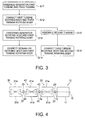
- the second embodiment shown in FIGS. 4 and 5 differs from the first embodiment of FIGS. 1 to 3 primarily in that an upper-half housing of a third turbine is assembled after the step of coupling an electric power generator rotating body and a first turbine rotating body together.
- the other configurations of the second embodiment are substantially the same as those of the first embodiment. It should be noted that with reference to FIGS. 4 and 5 , the same reference number is assigned to each of the same elements as those of the first embodiment shown in FIGS. 1 to 3 , and detailed description is thus omitted.
- FIG. 2 indicates that as described above, even in a case where the first turbine rotating body 22 is not connected to a third turbine rotating body 42, the first turbine rotating body 22 still could be centered relative to the generator rotating body 12 and then be connected to the generator rotating body 12. This means that even in a case where the upper-half housing 41a of the third turbine 40 is not mounted, the first turbine rotating body 22 that has been connected to the third turbine rotating body 42 still could be centered relative to and connected to the generator rotating body 12.
- the generator 10 and the first turbine 20 are assembled and the third turbine 40 is assembled to a state in which the upper-half housing 41a is not mounted (step S21). That is to say, the lower-half housing 41b of the third turbine 40 is disposed in a predetermined position and the third turbine rotating body 42 is mounted in the lower-half housing 41b. The upper-half housing 41a is not mounted at this phase.
- step S22 the first turbine rotating body 22 and the third turbine rotating body 42 are connected (step S22).
- step S23 a first coupling 13 of the generator rotating body 12 and a second coupling 23 of the first turbine rotating body 22 are centered first (step S23).
- the first coupling 13 and the second coupling 23 are subsequently connected (step S24).
- the upper-half housing 41a of the third turbine 40 is mounted on the lower-half housing 41b (step S25).
- step S26 the second turbine 30 is assembled (step S26).
- a second turbine rotating body 32 is connected to the first turbine rotating body 22 via the third turbine rotating body 42 (step S27).
- the generator 10 the first turbine 20, the third turbine 40, and the second turbine 30 are coupled together.
- the upper-half housing 41a of the third turbine 40 is mounted on the lower-half housing 41b after the step of centering and then connecting the generator rotating body 12 and the first turbine rotating body 22.
- the centering of the generator rotating body 12 and the first turbine rotating body 22 can be started.
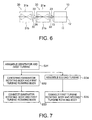
- the third embodiment shown in FIGS. 6 and 7 differs from the first embodiment of FIGS. 1 to 3 primarily in that a third turbine is not disposed between a first turbine and a second turbine.
- the other configurations of the third embodiment are substantially the same as those of the first embodiment.
- the same reference number is assigned to each of the same elements as those of the first embodiment shown in FIGS. 1 to 3 , and detailed description is thus omitted.
- the third turbine 40 is not disposed between the first turbine 20 and the second turbine 30. That is to say, in the present embodiment, the first turbine 20 and the second turbine 30 are coupled to the generator 10.
- FIG. 2 indicates that as described above, even in a case where a first turbine rotating body 22 is not connected to a third turbine rotating body 42, the first turbine rotating body 22 still could be centered relative to a generator rotating body 12 and then connected to the generator rotating body 12.
- the generator rotating body 12 still could be centered relative to the first turbine rotating body 22 and then connected to the first turbine rotating body 22 in a state that the first turbine rotating body 22 is not connected to a second turbine rotating body 32.
- the second turbine 30 still could be assembled in parallel with or after the step of centering the generator rotating body 12 and the first turbine rotating body 22.
- the first turbine rotating body 22 and the second turbine rotating body 32 could be connected in parallel with or after the step of centering the generator rotating body 12 and the first turbine rotating body 22.
- the generator 10 and the first turbine 20 are assembled (step S31).
- step S32 a first coupling 13 of the generator rotating body 12 and a second coupling 23 of the first turbine rotating body 22 are centered first (step S32).
- the first coupling 13 and the second coupling 23 are subsequently connected (step S33).
- step S34 the second turbine rotating body 32 is connected to the first turbine rotating body 22 (step S35).
- the generator 10, the first turbine 20, and the second turbine 30 are coupled in this manner.
- the second turbine 30 still could be assembled or the first turbine rotating body 22 and the second turbine rotating body 32 can be connected, in parallel with or after the step of centering the generator rotating body 12 and the first turbine rotating body 22.
- the connection of the generator rotating body 12 and the first turbine rotating body 22 can be started.
- the fourth embodiment shown in FIGS. 8 to 10 differs from the first embodiment of FIGS. 1 to 3 primarily in that an upper-half housing of a first turbine is mounted on a lower-half housing after the step of connecting an electric power generator rotating body and a first turbine rotating body.
- the other configurations of the fourth embodiment are substantially the same as those of the first embodiment.
- the same reference number is assigned to each of the same elements as those of the first embodiment shown in FIGS. 1 to 3 , and detailed description is thus omitted.
- a third turbine 40 is not disposed between the first turbine 20 and a second turbine 30. That is to say, in the present embodiment, the first turbine 20 and the second turbine 30 are coupled to the generator 10.
- FIG. 9 shows analytical results on deflection of the turbine rotating bodies 22 and 32 that occurs before these turbine rotating bodies are connected to the generator rotating body 12.
- Data marked with “a” in FIG. 9 represents the deflection of the first turbine rotating body 22 that occurs in a state that whereas the upper-half housing 21a of the first turbine 20 is mounted on the lower-half housing 21b, the first turbine rotating body 22 and a second turbine rotating body 32 are not connected.
- Data marked with “b” represents the deflection of the first turbine rotating body 22 that occurs in a state that the upper-half housing 21a of the first turbine 20 is not mounted on the lower-half housing 21b and the connection of the first turbine rotating body 22 and the second turbine rotating body 32 are not connected.
- a position of a second coupling 23 disposed at a side of the first turbine rotating body 22 that faces the generator 10 is substantially constant, irrespective of whether the upper-half housing 21a of the first turbine 20 is mounted on the lower-half housing 21b.
- the position of the second coupling 23, indicated as data "b" where the upper-half housing 21a is not mounted is equal to or less than a determined reference value.
- the above position of the second coupling 23 is substantially the same as a position of the second coupling 23 that is indicated as data "a" where the upper-half housing 21a is already mounted.
- the generator 10 is assembled while the first turbine 20 is assembled to a state in which the upper-half housing 21a is not mounted (step S41). More specifically, the lower-half housing 21b of the first turbine 20 is disposed in a predetermined position and then the first turbine rotating body 22 is installed in the lower-half housing 21b. The upper-half housing 21a is not mounted at this phase.
- step S42 the generator rotating body 12 and the first turbine rotating body 22 are centered and then connected.
- step S43 the first coupling 13 of the generator rotating body 12 and the second coupling 23 of the first turbine rotating body 22 are first centered.
- the lower-half housing 21b of the first turbine 20 is mounted in the lower-half housing 21b (step S44).
- step S45 the second turbine rotating body 32 is connected to the first turbine rotating body 22 (step S45).
- the generator 10, the first turbine 20, and the second turbine 30 are coupled in this manner.
- the upper-half housing 21a of the first turbine 20 is mounted on the lower-half housing 21b after the step of centering and then connecting the generator rotating body 12 and the first turbine rotating body 22.
- the centering of the generator rotating body 12 and the first turbine rotating body 22 can be started.
- the second coupling 23 of the first turbine rotating body 22 may be offset in step S42, that is, the step of centering the generator rotating body 12 and the first turbine rotating body 22.
- Data marked with "c” in FIG. 9 represents the deflection of the first turbine rotating body 22 that occurs in the state that the upper-half housing 21a of the first turbine 20 is not mounted on the lower-half housing 21b and the connection of the first turbine rotating body 22 and the second turbine rotating body 32 are not connected.
- the degree of misalignment of the second coupling 23 in this case is relatively significant. This could cause a situation not allowing the misalignment (i.e., shift in central position) between the first coupling 13 and the second coupling 23 to be absorbed during the centering of the generator rotating body 12 and the first turbine rotating body 22.
- the second coupling 23 at the side of the first turbine rotating body 22 that faces the generator 10 would be suitably offset with a predetermined offset value.
- This offset value should preferably be equivalent to a difference between the position of the second coupling 23 existing when the upper-half housing 21a of the first turbine 20 is already mounted on the lower-half housing 21b and the position of the second coupling 23 existing when the upper-half housing 21a is not mounted.
- the position of the second coupling 23 present at an end of the first turbine rotating body 22 could change as shown in FIG. 11 .
- a deflection of the first turbine rotating body 22 without the upper-half housing 21a mounted in place is shown with dotted line "r"
- a deflection of the first turbine rotating body 22 with the upper-half housing 21a mounted in place is shown with solid line "s”.
- the position of the second coupling 23 would be suitably offset downward with the above offset value that is equivalent to the difference between the position of the second coupling 23 existing when the upper-half housing 21a of the first turbine 20 is mounted on the lower-half housing 21b and the position of the second coupling 23 existing when the upper-half housing 21a is not mounted.
- the offset value should preferably be calculated from, for example, analysis or the like in advance.
- Offsetting the second coupling 23 in this way allows the connection of this coupling to the first coupling 13 of the generator rotating body 12 by displacing the second coupling 23 to the position in which the upper-half housing 21a of the first turbine 20 has been mounted.
- This connecting operation in turn allows the generator rotating body 12 and the first turbine rotating body 22 to be centered and connected before the upper-half housing 21a of the first turbine 20 is mounted, and thereby enables the operating efficiency to be improved.
- a jack-up device (not shown), for example, can be used to offset the coupling. The jack-up device may be removed after the installation of the upper-half housing 21a.
- the adjustment of the bearing corresponding to the second coupling 23 can be unnecessary if the second coupling 23 is offset.
- the offset value may be assigned as the difference between the position of the second coupling 23 existing when the second turbine rotating body 32 is connected to the first turbine rotating body 22, and the position of the second coupling 23 existing when the second turbine rotating body 32 is not connected.
- the position of the second coupling 23 present at the end of the first turbine rotating body 22 could change as shown in FIG. 12 .
- a deflection of the first turbine rotating body 22 existing before the second turbine rotating body 32 is connected is shown with solid line "t”
- a deflection of the first turbine rotating body 22 with the second turbine rotating body 32 connected is shown with dotted line "u”.
- the position of the second coupling 23 would be suitably offset upward with the above offset value that is equivalent to the difference between the position of the second coupling 23 existing when the second turbine rotating body 32 is connected to the first turbine rotating body 22, and the position of the second coupling 23 existing when the second turbine rotating body 32 is not connected.
- the offset value should preferably be calculated from, for example, analysis or the like in advance. Offsetting the second coupling 23 in this way allows the connection of this coupling to the first coupling 13 of the generator rotating body 12 by displacing the second coupling 23 to the position in which the second turbine rotating body 32 has been connected to the first turbine rotating body 22. This connecting operation in turn allows the generator rotating body 12 and the first turbine rotating body 22 to be centered and connected before the second turbine rotating body 32 is connected, and thereby enables the operating efficiency to be improved.
- the offset value to be assigned for the second coupling 23 may instead be set as a value obtained by combining the offset values shown in FIGS. 11 and 12 .
- the second coupling 23 can then be connected to the first coupling 13 of the generator rotating body 12 by displacing the second coupling 23 to the position that the second coupling 23 will take when the upper-half housing 21a of the first turbine 20 is mounted and the second turbine rotating body 32 is connected to the first turbine rotating body 22.
- the connection operation in turn allows the generator rotating body 12 and the first turbine rotating body 22 to be centered and connected before the upper-half housing 21a of the first turbine 20 is mounted and the second turbine rotating body 32 is connected, and thereby enables the operating efficiency to be improved.
- the operating efficiency of coupling the power generator and the turbine can be improved.
Landscapes
- Engineering & Computer Science (AREA)
- Mechanical Engineering (AREA)
- General Engineering & Computer Science (AREA)
- Power Engineering (AREA)
- Connection Of Motors, Electrical Generators, Mechanical Devices, And The Like (AREA)
- Manufacture Of Motors, Generators (AREA)
Applications Claiming Priority (1)
| Application Number | Priority Date | Filing Date | Title |
|---|---|---|---|
| JP2014035804A JP6190289B2 (ja) | 2014-02-26 | 2014-02-26 | 発電機とタービンの連結方法 |
Publications (3)
| Publication Number | Publication Date |
|---|---|
| EP2913484A2 true EP2913484A2 (fr) | 2015-09-02 |
| EP2913484A3 EP2913484A3 (fr) | 2015-11-25 |
| EP2913484B1 EP2913484B1 (fr) | 2018-05-09 |
Family
ID=52779450
Family Applications (1)
| Application Number | Title | Priority Date | Filing Date |
|---|---|---|---|
| EP15153087.0A Not-in-force EP2913484B1 (fr) | 2014-02-26 | 2015-01-29 | Générateur d'énergie et procédé de couplage de turbine |
Country Status (5)
| Country | Link |
|---|---|
| US (1) | US20150244240A1 (fr) |
| EP (1) | EP2913484B1 (fr) |
| JP (1) | JP6190289B2 (fr) |
| BR (1) | BR102015003296B1 (fr) |
| ES (1) | ES2683276T3 (fr) |
Family Cites Families (10)
| Publication number | Priority date | Publication date | Assignee | Title |
|---|---|---|---|---|
| SE387408B (sv) * | 1974-12-23 | 1976-09-06 | Stal Laval Turbin Ab | Forfarande vid montage i en maskinhall av ett gasturbinaggregat |
| JPS5489104A (en) * | 1977-12-26 | 1979-07-14 | Hitachi Ltd | Method of adjusting alignment of body of revolution |
| JPS62228605A (ja) * | 1986-03-31 | 1987-10-07 | Toshiba Corp | 蒸気タ−ビンの据付方法およびタ−ビンロ−タ |
| JP2619132B2 (ja) * | 1990-09-14 | 1997-06-11 | 株式会社東芝 | 蒸気タービンの軸受支持装置 |
| JPH04194303A (ja) * | 1990-11-28 | 1992-07-14 | Hitachi Ltd | 一軸型コンバインド発電設備 |
| US6594555B2 (en) * | 2000-12-21 | 2003-07-15 | General Electric Company | Method for steam turbine halfshell alignment |
| JP2007032504A (ja) * | 2005-07-29 | 2007-02-08 | Toshiba Corp | 蒸気タービンの内部構成部品の位置調整方法とこの方法で用いられる計測装置 |
| US8590151B2 (en) * | 2006-06-30 | 2013-11-26 | Solar Turbines Inc. | System for supporting and servicing a gas turbine engine |
| JP5422338B2 (ja) * | 2009-10-22 | 2014-02-19 | 株式会社東芝 | 蒸気タービン車室の位置合わせ方法および蒸気タービンの組立方法 |
| US9163514B2 (en) * | 2012-03-30 | 2015-10-20 | General Electric Company | System and method for coupling rotor components |
-
2014
- 2014-02-26 JP JP2014035804A patent/JP6190289B2/ja active Active
-
2015
- 2015-01-28 US US14/607,250 patent/US20150244240A1/en not_active Abandoned
- 2015-01-29 ES ES15153087.0T patent/ES2683276T3/es active Active
- 2015-01-29 EP EP15153087.0A patent/EP2913484B1/fr not_active Not-in-force
- 2015-02-13 BR BR102015003296-0A patent/BR102015003296B1/pt not_active IP Right Cessation
Non-Patent Citations (1)
| Title |
|---|
| None |
Also Published As
| Publication number | Publication date |
|---|---|
| JP2015161199A (ja) | 2015-09-07 |
| BR102015003296B1 (pt) | 2022-11-16 |
| ES2683276T3 (es) | 2018-09-25 |
| US20150244240A1 (en) | 2015-08-27 |
| EP2913484B1 (fr) | 2018-05-09 |
| EP2913484A3 (fr) | 2015-11-25 |
| JP6190289B2 (ja) | 2017-08-30 |
| BR102015003296A2 (pt) | 2017-11-07 |
Similar Documents
| Publication | Publication Date | Title |
|---|---|---|
| US10400622B2 (en) | Guide vane adjusting device and turbomachine | |
| EP2754892B1 (fr) | Procédé d'assemblage d'une ligne d'arbres d'un dispositif générateur de puissance à énergie récupérée, et outil d'assemblage d'une ligne d'arbres | |
| US10669882B2 (en) | Variable stator blade operating device | |
| US9810100B2 (en) | Barring gear assembly for driving in rotation a shaft of a turbo-alternator group | |
| EP2617966B1 (fr) | Boîtier d'accessoire de moteur à turbine à gaz | |
| EP2387132A2 (fr) | Rotor pour machine électrique tournante | |
| JP5055208B2 (ja) | 軸流圧縮機の可変静翼駆動方法及び装置 | |
| US10038357B2 (en) | Method for repairing or servicing a wye ring | |
| US20120227536A1 (en) | Sectioned tuning ring for rotating body | |
| JP2010273535A (ja) | 発電機ステータ取付けのためのシステムおよび方法 | |
| US20130223775A1 (en) | Journal Bearing Device | |
| KR20170080561A (ko) | 풍력 발전기 및 풍력 발전기 세트 | |
| EP2557277B1 (fr) | Procédé et appareil pour faciliter l'assemblage d'un carter de turbine | |
| KR20140004648A (ko) | 배기가스 터보차저 | |
| CN101625283B (zh) | 双向推力轴承试验装置 | |
| US9611759B2 (en) | Apparatus and method for adjusting an inner casing of a turbomachine | |
| EP2803821A1 (fr) | Dispositif d'aube, système d'aubes et procédé de fabrication associé d'un système d'aubes | |
| EP2913484B1 (fr) | Générateur d'énergie et procédé de couplage de turbine | |
| US20170114802A1 (en) | Compressor | |
| EP2392784A1 (fr) | Ensemble de turbine à vapeur et procédé d'assemblage d'une turbine à vapeur | |
| EP3561240B1 (fr) | Joint d'étanchéité en carbone | |
| US12113408B2 (en) | Wind generator rotor connection replacement | |
| US10487691B2 (en) | Rotary machine unit | |
| EP2706200B1 (fr) | Procédé pour enlever un carter interne d'une machine | |
| US20050116552A1 (en) | Turbine generator vibration damper system |
Legal Events
| Date | Code | Title | Description |
|---|---|---|---|
| PUAI | Public reference made under article 153(3) epc to a published international application that has entered the european phase |
Free format text: ORIGINAL CODE: 0009012 |
|
| 17P | Request for examination filed |
Effective date: 20150129 |
|
| AK | Designated contracting states |
Kind code of ref document: A2 Designated state(s): AL AT BE BG CH CY CZ DE DK EE ES FI FR GB GR HR HU IE IS IT LI LT LU LV MC MK MT NL NO PL PT RO RS SE SI SK SM TR |
|
| AX | Request for extension of the european patent |
Extension state: BA ME |
|
| PUAL | Search report despatched |
Free format text: ORIGINAL CODE: 0009013 |
|
| AK | Designated contracting states |
Kind code of ref document: A3 Designated state(s): AL AT BE BG CH CY CZ DE DK EE ES FI FR GB GR HR HU IE IS IT LI LT LU LV MC MK MT NL NO PL PT RO RS SE SI SK SM TR |
|
| AX | Request for extension of the european patent |
Extension state: BA ME |
|
| RIC1 | Information provided on ipc code assigned before grant |
Ipc: F01D 15/10 20060101AFI20151022BHEP |
|
| STAA | Information on the status of an ep patent application or granted ep patent |
Free format text: STATUS: EXAMINATION IS IN PROGRESS |
|
| 17Q | First examination report despatched |
Effective date: 20170123 |
|
| REG | Reference to a national code |
Ref country code: DE Ref legal event code: R079 Ref document number: 602015010836 Country of ref document: DE Free format text: PREVIOUS MAIN CLASS: F01D0015100000 Ipc: F01D0013000000 |
|
| GRAP | Despatch of communication of intention to grant a patent |
Free format text: ORIGINAL CODE: EPIDOSNIGR1 |
|
| STAA | Information on the status of an ep patent application or granted ep patent |
Free format text: STATUS: GRANT OF PATENT IS INTENDED |
|
| RIC1 | Information provided on ipc code assigned before grant |
Ipc: H02K 7/18 20060101ALI20171020BHEP Ipc: F01D 13/00 20060101AFI20171020BHEP Ipc: F01D 15/10 20060101ALI20171020BHEP |
|
| INTG | Intention to grant announced |
Effective date: 20171121 |
|
| GRAS | Grant fee paid |
Free format text: ORIGINAL CODE: EPIDOSNIGR3 |
|
| GRAA | (expected) grant |
Free format text: ORIGINAL CODE: 0009210 |
|
| STAA | Information on the status of an ep patent application or granted ep patent |
Free format text: STATUS: THE PATENT HAS BEEN GRANTED |
|
| AK | Designated contracting states |
Kind code of ref document: B1 Designated state(s): AL AT BE BG CH CY CZ DE DK EE ES FI FR GB GR HR HU IE IS IT LI LT LU LV MC MK MT NL NO PL PT RO RS SE SI SK SM TR |
|
| REG | Reference to a national code |
Ref country code: GB Ref legal event code: FG4D |
|
| REG | Reference to a national code |
Ref country code: CH Ref legal event code: EP Ref country code: AT Ref legal event code: REF Ref document number: 997747 Country of ref document: AT Kind code of ref document: T Effective date: 20180515 |
|
| REG | Reference to a national code |
Ref country code: IE Ref legal event code: FG4D |
|
| REG | Reference to a national code |
Ref country code: DE Ref legal event code: R096 Ref document number: 602015010836 Country of ref document: DE |
|
| REG | Reference to a national code |
Ref country code: NL Ref legal event code: MP Effective date: 20180509 |
|
| REG | Reference to a national code |
Ref country code: LT Ref legal event code: MG4D Ref country code: ES Ref legal event code: FG2A Ref document number: 2683276 Country of ref document: ES Kind code of ref document: T3 Effective date: 20180925 |
|
| PG25 | Lapsed in a contracting state [announced via postgrant information from national office to epo] |
Ref country code: SE Free format text: LAPSE BECAUSE OF FAILURE TO SUBMIT A TRANSLATION OF THE DESCRIPTION OR TO PAY THE FEE WITHIN THE PRESCRIBED TIME-LIMIT Effective date: 20180509 Ref country code: LT Free format text: LAPSE BECAUSE OF FAILURE TO SUBMIT A TRANSLATION OF THE DESCRIPTION OR TO PAY THE FEE WITHIN THE PRESCRIBED TIME-LIMIT Effective date: 20180509 Ref country code: NO Free format text: LAPSE BECAUSE OF FAILURE TO SUBMIT A TRANSLATION OF THE DESCRIPTION OR TO PAY THE FEE WITHIN THE PRESCRIBED TIME-LIMIT Effective date: 20180809 Ref country code: FI Free format text: LAPSE BECAUSE OF FAILURE TO SUBMIT A TRANSLATION OF THE DESCRIPTION OR TO PAY THE FEE WITHIN THE PRESCRIBED TIME-LIMIT Effective date: 20180509 |
|
| PG25 | Lapsed in a contracting state [announced via postgrant information from national office to epo] |
Ref country code: GR Free format text: LAPSE BECAUSE OF FAILURE TO SUBMIT A TRANSLATION OF THE DESCRIPTION OR TO PAY THE FEE WITHIN THE PRESCRIBED TIME-LIMIT Effective date: 20180810 Ref country code: RS Free format text: LAPSE BECAUSE OF FAILURE TO SUBMIT A TRANSLATION OF THE DESCRIPTION OR TO PAY THE FEE WITHIN THE PRESCRIBED TIME-LIMIT Effective date: 20180509 Ref country code: HR Free format text: LAPSE BECAUSE OF FAILURE TO SUBMIT A TRANSLATION OF THE DESCRIPTION OR TO PAY THE FEE WITHIN THE PRESCRIBED TIME-LIMIT Effective date: 20180509 Ref country code: NL Free format text: LAPSE BECAUSE OF FAILURE TO SUBMIT A TRANSLATION OF THE DESCRIPTION OR TO PAY THE FEE WITHIN THE PRESCRIBED TIME-LIMIT Effective date: 20180509 Ref country code: LV Free format text: LAPSE BECAUSE OF FAILURE TO SUBMIT A TRANSLATION OF THE DESCRIPTION OR TO PAY THE FEE WITHIN THE PRESCRIBED TIME-LIMIT Effective date: 20180509 |
|
| REG | Reference to a national code |
Ref country code: AT Ref legal event code: MK05 Ref document number: 997747 Country of ref document: AT Kind code of ref document: T Effective date: 20180509 |
|
| PG25 | Lapsed in a contracting state [announced via postgrant information from national office to epo] |
Ref country code: SK Free format text: LAPSE BECAUSE OF FAILURE TO SUBMIT A TRANSLATION OF THE DESCRIPTION OR TO PAY THE FEE WITHIN THE PRESCRIBED TIME-LIMIT Effective date: 20180509 Ref country code: EE Free format text: LAPSE BECAUSE OF FAILURE TO SUBMIT A TRANSLATION OF THE DESCRIPTION OR TO PAY THE FEE WITHIN THE PRESCRIBED TIME-LIMIT Effective date: 20180509 Ref country code: PL Free format text: LAPSE BECAUSE OF FAILURE TO SUBMIT A TRANSLATION OF THE DESCRIPTION OR TO PAY THE FEE WITHIN THE PRESCRIBED TIME-LIMIT Effective date: 20180509 Ref country code: DK Free format text: LAPSE BECAUSE OF FAILURE TO SUBMIT A TRANSLATION OF THE DESCRIPTION OR TO PAY THE FEE WITHIN THE PRESCRIBED TIME-LIMIT Effective date: 20180509 Ref country code: RO Free format text: LAPSE BECAUSE OF FAILURE TO SUBMIT A TRANSLATION OF THE DESCRIPTION OR TO PAY THE FEE WITHIN THE PRESCRIBED TIME-LIMIT Effective date: 20180509 Ref country code: CZ Free format text: LAPSE BECAUSE OF FAILURE TO SUBMIT A TRANSLATION OF THE DESCRIPTION OR TO PAY THE FEE WITHIN THE PRESCRIBED TIME-LIMIT Effective date: 20180509 Ref country code: AT Free format text: LAPSE BECAUSE OF FAILURE TO SUBMIT A TRANSLATION OF THE DESCRIPTION OR TO PAY THE FEE WITHIN THE PRESCRIBED TIME-LIMIT Effective date: 20180509 |
|
| REG | Reference to a national code |
Ref country code: DE Ref legal event code: R097 Ref document number: 602015010836 Country of ref document: DE |
|
| PG25 | Lapsed in a contracting state [announced via postgrant information from national office to epo] |
Ref country code: SM Free format text: LAPSE BECAUSE OF FAILURE TO SUBMIT A TRANSLATION OF THE DESCRIPTION OR TO PAY THE FEE WITHIN THE PRESCRIBED TIME-LIMIT Effective date: 20180509 Ref country code: IT Free format text: LAPSE BECAUSE OF FAILURE TO SUBMIT A TRANSLATION OF THE DESCRIPTION OR TO PAY THE FEE WITHIN THE PRESCRIBED TIME-LIMIT Effective date: 20180509 |
|
| PLBE | No opposition filed within time limit |
Free format text: ORIGINAL CODE: 0009261 |
|
| STAA | Information on the status of an ep patent application or granted ep patent |
Free format text: STATUS: NO OPPOSITION FILED WITHIN TIME LIMIT |
|
| 26N | No opposition filed |
Effective date: 20190212 |
|
| PG25 | Lapsed in a contracting state [announced via postgrant information from national office to epo] |
Ref country code: SI Free format text: LAPSE BECAUSE OF FAILURE TO SUBMIT A TRANSLATION OF THE DESCRIPTION OR TO PAY THE FEE WITHIN THE PRESCRIBED TIME-LIMIT Effective date: 20180509 |
|
| REG | Reference to a national code |
Ref country code: DE Ref legal event code: R119 Ref document number: 602015010836 Country of ref document: DE |
|
| PG25 | Lapsed in a contracting state [announced via postgrant information from national office to epo] |
Ref country code: MC Free format text: LAPSE BECAUSE OF FAILURE TO SUBMIT A TRANSLATION OF THE DESCRIPTION OR TO PAY THE FEE WITHIN THE PRESCRIBED TIME-LIMIT Effective date: 20180509 |
|
| REG | Reference to a national code |
Ref country code: CH Ref legal event code: PL |
|
| GBPC | Gb: european patent ceased through non-payment of renewal fee |
Effective date: 20190129 |
|
| PG25 | Lapsed in a contracting state [announced via postgrant information from national office to epo] |
Ref country code: LU Free format text: LAPSE BECAUSE OF NON-PAYMENT OF DUE FEES Effective date: 20190129 |
|
| REG | Reference to a national code |
Ref country code: BE Ref legal event code: MM Effective date: 20190131 |
|
| REG | Reference to a national code |
Ref country code: IE Ref legal event code: MM4A |
|
| PG25 | Lapsed in a contracting state [announced via postgrant information from national office to epo] |
Ref country code: DE Free format text: LAPSE BECAUSE OF NON-PAYMENT OF DUE FEES Effective date: 20190801 |
|
| PG25 | Lapsed in a contracting state [announced via postgrant information from national office to epo] |
Ref country code: BE Free format text: LAPSE BECAUSE OF NON-PAYMENT OF DUE FEES Effective date: 20190131 Ref country code: AL Free format text: LAPSE BECAUSE OF FAILURE TO SUBMIT A TRANSLATION OF THE DESCRIPTION OR TO PAY THE FEE WITHIN THE PRESCRIBED TIME-LIMIT Effective date: 20180509 |
|
| PG25 | Lapsed in a contracting state [announced via postgrant information from national office to epo] |
Ref country code: LI Free format text: LAPSE BECAUSE OF NON-PAYMENT OF DUE FEES Effective date: 20190131 Ref country code: CH Free format text: LAPSE BECAUSE OF NON-PAYMENT OF DUE FEES Effective date: 20190131 Ref country code: GB Free format text: LAPSE BECAUSE OF NON-PAYMENT OF DUE FEES Effective date: 20190129 |
|
| PG25 | Lapsed in a contracting state [announced via postgrant information from national office to epo] |
Ref country code: IE Free format text: LAPSE BECAUSE OF NON-PAYMENT OF DUE FEES Effective date: 20190129 |
|
| PG25 | Lapsed in a contracting state [announced via postgrant information from national office to epo] |
Ref country code: TR Free format text: LAPSE BECAUSE OF FAILURE TO SUBMIT A TRANSLATION OF THE DESCRIPTION OR TO PAY THE FEE WITHIN THE PRESCRIBED TIME-LIMIT Effective date: 20180509 |
|
| PG25 | Lapsed in a contracting state [announced via postgrant information from national office to epo] |
Ref country code: MT Free format text: LAPSE BECAUSE OF NON-PAYMENT OF DUE FEES Effective date: 20190129 Ref country code: PT Free format text: LAPSE BECAUSE OF FAILURE TO SUBMIT A TRANSLATION OF THE DESCRIPTION OR TO PAY THE FEE WITHIN THE PRESCRIBED TIME-LIMIT Effective date: 20180910 |
|
| PG25 | Lapsed in a contracting state [announced via postgrant information from national office to epo] |
Ref country code: CY Free format text: LAPSE BECAUSE OF FAILURE TO SUBMIT A TRANSLATION OF THE DESCRIPTION OR TO PAY THE FEE WITHIN THE PRESCRIBED TIME-LIMIT Effective date: 20180509 |
|
| PG25 | Lapsed in a contracting state [announced via postgrant information from national office to epo] |
Ref country code: IS Free format text: LAPSE BECAUSE OF FAILURE TO SUBMIT A TRANSLATION OF THE DESCRIPTION OR TO PAY THE FEE WITHIN THE PRESCRIBED TIME-LIMIT Effective date: 20180909 |
|
| PG25 | Lapsed in a contracting state [announced via postgrant information from national office to epo] |
Ref country code: HU Free format text: LAPSE BECAUSE OF FAILURE TO SUBMIT A TRANSLATION OF THE DESCRIPTION OR TO PAY THE FEE WITHIN THE PRESCRIBED TIME-LIMIT; INVALID AB INITIO Effective date: 20150129 |
|
| PG25 | Lapsed in a contracting state [announced via postgrant information from national office to epo] |
Ref country code: MK Free format text: LAPSE BECAUSE OF FAILURE TO SUBMIT A TRANSLATION OF THE DESCRIPTION OR TO PAY THE FEE WITHIN THE PRESCRIBED TIME-LIMIT Effective date: 20180509 |
|
| PGFP | Annual fee paid to national office [announced via postgrant information from national office to epo] |
Ref country code: FR Payment date: 20221208 Year of fee payment: 9 |
|
| PGFP | Annual fee paid to national office [announced via postgrant information from national office to epo] |
Ref country code: ES Payment date: 20230216 Year of fee payment: 9 |
|
| PGFP | Annual fee paid to national office [announced via postgrant information from national office to epo] |
Ref country code: BG Payment date: 20231204 Year of fee payment: 10 |
|
| PG25 | Lapsed in a contracting state [announced via postgrant information from national office to epo] |
Ref country code: FR Free format text: LAPSE BECAUSE OF NON-PAYMENT OF DUE FEES Effective date: 20240131 |
|
| PG25 | Lapsed in a contracting state [announced via postgrant information from national office to epo] |
Ref country code: FR Free format text: LAPSE BECAUSE OF NON-PAYMENT OF DUE FEES Effective date: 20240131 |
|
| REG | Reference to a national code |
Ref country code: ES Ref legal event code: FD2A Effective date: 20250310 |
|
| PG25 | Lapsed in a contracting state [announced via postgrant information from national office to epo] |
Ref country code: ES Free format text: LAPSE BECAUSE OF NON-PAYMENT OF DUE FEES Effective date: 20240130 |
|
| PG25 | Lapsed in a contracting state [announced via postgrant information from national office to epo] |
Ref country code: BG Free format text: LAPSE BECAUSE OF NON-PAYMENT OF DUE FEES Effective date: 20250129 |