EP2913208A1 - Attelage doté d'une unité de contact de véhicule - Google Patents
Attelage doté d'une unité de contact de véhicule Download PDFInfo
- Publication number
- EP2913208A1 EP2913208A1 EP15156708.8A EP15156708A EP2913208A1 EP 2913208 A1 EP2913208 A1 EP 2913208A1 EP 15156708 A EP15156708 A EP 15156708A EP 2913208 A1 EP2913208 A1 EP 2913208A1
- Authority
- EP
- European Patent Office
- Prior art keywords
- contact
- vehicle
- electrical
- trailer
- coupling arm
- Prior art date
- Legal status (The legal status is an assumption and is not a legal conclusion. Google has not performed a legal analysis and makes no representation as to the accuracy of the status listed.)
- Granted
Links
- 230000008878 coupling Effects 0.000 claims abstract description 121
- 238000010168 coupling process Methods 0.000 claims abstract description 121
- 238000005859 coupling reaction Methods 0.000 claims abstract description 121
- 238000004891 communication Methods 0.000 claims description 8
- 229910052751 metal Inorganic materials 0.000 claims description 4
- 239000002184 metal Substances 0.000 claims description 4
- 230000013011 mating Effects 0.000 claims description 2
- 230000005540 biological transmission Effects 0.000 claims 1
- 238000004519 manufacturing process Methods 0.000 description 4
- 238000009420 retrofitting Methods 0.000 description 3
- XEEYBQQBJWHFJM-UHFFFAOYSA-N Iron Chemical compound [Fe] XEEYBQQBJWHFJM-UHFFFAOYSA-N 0.000 description 2
- 230000008901 benefit Effects 0.000 description 2
- 238000005516 engineering process Methods 0.000 description 2
- 238000003780 insertion Methods 0.000 description 2
- 230000037431 insertion Effects 0.000 description 2
- 238000009413 insulation Methods 0.000 description 2
- 239000000463 material Substances 0.000 description 2
- 230000007246 mechanism Effects 0.000 description 2
- 230000003647 oxidation Effects 0.000 description 2
- 238000007254 oxidation reaction Methods 0.000 description 2
- 241001236644 Lavinia Species 0.000 description 1
- 229910000831 Steel Inorganic materials 0.000 description 1
- 238000004026 adhesive bonding Methods 0.000 description 1
- 229910052782 aluminium Inorganic materials 0.000 description 1
- XAGFODPZIPBFFR-UHFFFAOYSA-N aluminium Chemical compound [Al] XAGFODPZIPBFFR-UHFFFAOYSA-N 0.000 description 1
- 230000009286 beneficial effect Effects 0.000 description 1
- 230000000903 blocking effect Effects 0.000 description 1
- 238000005266 casting Methods 0.000 description 1
- 238000010292 electrical insulation Methods 0.000 description 1
- 239000012777 electrically insulating material Substances 0.000 description 1
- 230000007613 environmental effect Effects 0.000 description 1
- 238000005242 forging Methods 0.000 description 1
- 229910052742 iron Inorganic materials 0.000 description 1
- 238000000034 method Methods 0.000 description 1
- 238000012544 monitoring process Methods 0.000 description 1
- 229910000510 noble metal Inorganic materials 0.000 description 1
- 230000008569 process Effects 0.000 description 1
- 238000012545 processing Methods 0.000 description 1
- 239000010959 steel Substances 0.000 description 1
- 238000003860 storage Methods 0.000 description 1
- XLYOFNOQVPJJNP-UHFFFAOYSA-N water Substances O XLYOFNOQVPJJNP-UHFFFAOYSA-N 0.000 description 1
Images


Classifications
-
- B—PERFORMING OPERATIONS; TRANSPORTING
- B60—VEHICLES IN GENERAL
- B60D—VEHICLE CONNECTIONS
- B60D1/00—Traction couplings; Hitches; Draw-gear; Towing devices
- B60D1/58—Auxiliary devices
- B60D1/62—Auxiliary devices involving supply lines, electric circuits, or the like
- B60D1/64—Couplings or joints therefor
-
- B—PERFORMING OPERATIONS; TRANSPORTING
- B60—VEHICLES IN GENERAL
- B60D—VEHICLE CONNECTIONS
- B60D1/00—Traction couplings; Hitches; Draw-gear; Towing devices
- B60D1/01—Traction couplings or hitches characterised by their type
- B60D1/06—Ball-and-socket hitches, e.g. constructional details, auxiliary devices, their arrangement on the vehicle
-
- B—PERFORMING OPERATIONS; TRANSPORTING
- B60—VEHICLES IN GENERAL
- B60D—VEHICLE CONNECTIONS
- B60D1/00—Traction couplings; Hitches; Draw-gear; Towing devices
- B60D1/48—Traction couplings; Hitches; Draw-gear; Towing devices characterised by the mounting
- B60D1/52—Traction couplings; Hitches; Draw-gear; Towing devices characterised by the mounting removably mounted
-
- B—PERFORMING OPERATIONS; TRANSPORTING
- B60—VEHICLES IN GENERAL
- B60D—VEHICLE CONNECTIONS
- B60D1/00—Traction couplings; Hitches; Draw-gear; Towing devices
- B60D1/48—Traction couplings; Hitches; Draw-gear; Towing devices characterised by the mounting
- B60D1/54—Traction couplings; Hitches; Draw-gear; Towing devices characterised by the mounting collapsible or retractable when not in use, e.g. hide-away hitches
Definitions
- the invention relates to a towing hitch for a motor vehicle, with a coupling arm for coupling a trailer or a rear load carrier which protrudes in a position of use to the rear in front of the motor vehicle, wherein the coupling arm on a fastened to the motor vehicle or vehicle mount based on a male projection and a plug-in receptacle releasably attachable or mounted on the basis of a bearing between the use position and a closer to the motor vehicle off-set position, wherein the hitch has a fixing device for fixing the coupling arm to the vehicle mount, in which on the vehicle mount and the coupling arm next to the male projection and the plug-in receptacle or arranged next to the bearing positive locking contours interlocking with each other, wherein on the coupling arm, an electrical vehicle-contact unit with electrical connection contacts to elec trischen connection of an electric trailer contact unit of the trailer is arranged, which has at least one electrical connection line for connection to an electrical system of the motor vehicle.
- a coupling arm of a trailer coupling is at least in the position of use usually determined form-fitting contours with respect to the vehicle mount and thus secured. It is now also common that a socket on the coupling arm is arranged directly so that it is easily accessible when using the hitch.
- Such embodiments are in both so-called pivot systems, ie in trailer hitches, the coupling arm between a use position and a non-use position usually swivel, in some cases axially displaceable is stored.
- plug-in systems ie, for example, according to EP 2 199 118 A1 or DE 100 27 571 A1 It is known to arrange the socket, thus the vehicle contact unit, directly on the coupling arm.
- the production of electrical connections from the vehicle to an arranged on the coupling arm socket is relatively difficult to implement. For example, it requires sufficiently flexible cables (in the case of the aforementioned pivoting systems) or complicated electrical plug-in contact systems.
- electrical contact elements are arranged on the positive locking contours, which are in the use position of the coupling arm in contact with each other and provided for connection to the electrical system wiring system section and one with the vehicle Contact unit connected contact unit section of at least one electrical connection line with each other.
- the vehicle contact unit is, for example, a trailer socket, in particular a DIN-compliant or standard-compliant trailer socket.
- the vehicle contact unit is configured, for example, according to a European or German standard. For example, It has 7 contacts according to DIN 1724 or 13 contacts according to ISO 11446, for establishing an electrical connection with the trailer contact unit, ie a matching trailer plug.
- the vehicle contact unit is arranged in a manner known per se on the coupling arm, but the electrical contact outside of the bearing, with which the coupling arm between the use position and the non-use position movably mounted is, for example, pivotable about a pivot axis and / or slidably about a control axis (wherein the adjusting axis may be simultaneously the pivot axis), is provided.
- the usual in so-called plug-in systems connector between the coupling arm and vehicle mount is free of electrical contact elements.
- One advantage is that the connection mechanism between the vehicle mount and the coupling arm is not affected by the electrical components. You do not need to increase the space for the electrical connection between the vehicle bracket and coupling arm. Rather, the electrical contact takes place outside of this connection technology, namely the positive locking contours.
- the inventive concept is optimally suited for retrofitting, i. for example, a trailer hitch with a conventional one adjacent to the vehicle mount, e.g. On the cross member, arranged socket can be converted to a trailer hitch with socket (vehicle contact unit) directly on the coupling arm.
- the electrical connection technology namely the aforementioned contact elements, can be retrofitted so to speak in the region of the form-fitting contours. Also, a series production is simplified or implemented a common part principle.
- At least one contact element is required, which is electrically isolated from the base bodies of the vehicle mount and the coupling arm, while the other potential, for example a ground potential, can also be realized by the direct contact of the coupling arm with the vehicle mount.
- the main body of the vehicle mount and the coupling arm may constitute a contact element, while the other contact element is electrically isolated therefrom and transmits, for example, a supply potential for the vehicle contact unit.
- the contact elements are preferably not in direct force-loaded or positively acted on area of the positive locking contours.
- An advantageous embodiment of the invention provides that the contact elements are arranged next to in the position of use in contact with each other standing form-fitting surfaces of the form-fitting contours, so that the contact elements are unloaded by the positive contact of the form-fitting contours. Nevertheless, in the region of the form-fitting contours defined distances between on the one hand the coupling arm and the other hand, the vehicle mount so that the contact elements are optimally positioned to each other when the coupling arm occupies the position of use.
- the form-fitting contours can have any shape per se. It is conceivable, for example, that the form-fitting contours are undulating, V-shaped or the like. Also interengaging plug-in projections and plug-in receptacles, for example in the form of bolts and cylindrical plug receptacles or the like, may be provided in the manner according to the invention with one or more contact elements.
- a preferred embodiment of the invention provides that the form-fitting contours comprise at least one groove-shaped form-fitting receptacle and at least one matching form-fitting projection.
- positive locking receptacle and form-fitting projection are V-shaped or U-shaped. But also a rectangular in the side view shape is readily possible, that is, for example, the positive locking projection is bolt-like, while the positive locking receptacle is cylindrical, for example, includes a blind hole.
- a pairing consisting of a first and a second contact element of the arrangement of, for example, further contact elements are arranged opposite each other at a bottom of the at least one positive connection receptacle and a vertex area or frontal area, in particular on a free end face, of the at least one positive locking projection.
- the apex region or end region of the form-fitting projection is at the bottom of the positive-fit receptacle opposite, so that the two cooperating contact elements make electrical contact with each other.
- a respective contact element may have, for example, one or more electrical contact surfaces.
- the contact surfaces may have any contours, for example, be annular, rectangular or circular or the like.
- a respective contact element has a plurality of electrically isolated contact surfaces, for example, two or three contact surfaces.
- a contact element preferably has an electrically insulating holding body, e.g. made of plastic, and at least one electrical contact arranged thereon, for example a flat contact or a punctiform contact.
- the respective contact surfaces may be unsprung or, in a preferred embodiment, spring-loaded.
- a non-sprung, not in the direction of the opposite contact surfaces of the other contact element so to speak of self-moving contact surface is opposite a resilient contact surface or a spring contact.
- a plug-in holder for attaching at least one of the contact elements.
- a plug-in receptacle for inserting the respective contact element is provided.
- the plug-in receptacle may for example have a receiving channel, in which the contact element is inserted, so to speak.
- a mounting space for the respective contact element on the coupling arm or the vehicle mount is provided.
- an additional safety measure for example, a screw, gluing or the like, it is possible to secure the contact element to the plug-in holder.
- a contact unit holder for holding the vehicle contact unit is expediently provided on the coupling arm.
- the contact unit holder has e.g. in front of an arm body of the coupling arm projecting mounting tabs and / or mounting lugs or the like.
- the contact unit holder may also include a plug-in receptacle or the like for receiving the vehicle contact unit.
- a conduit for receiving at least a portion of the at least one connecting line can be arranged on the coupling arm or the vehicle mount or both.
- the duct or a portion thereof may be, for example, a tubular, i. act in the circumference closed, duct.
- a laterally open wiring, e.g. a groove-shaped channel is advantageous in the duct or a portion thereof.
- the plug-in holder or the contact unit holder or the conduit are expediently integral with a main body of the coupling arm or the vehicle holder.
- cutouts are provided.
- the main body of the coupling arm or the vehicle mount as a forging and / or casting the aforementioned components or configurations can be made, so to speak, the same with the respective basic coupling arm or the basic vehicle mount.
- a main body of the coupling arm and / or the vehicle mount is preferably made of metal, for example steel, iron, aluminum or the like.
- the contact unit section of the at least one connecting line expediently extends on an outer circumference of the coupling arm. It is also possible that two or more contact elements are each connected to the contact unit section, ie, that the contact unit section branches, for example, to the contact elements. Furthermore, it is possible that the Connecting lead from a first contact element leads to a second contact element, for example, with fewer wires or individual strands between the contact elements as to the first contact element.
- the hitch has two mutually arranged at an angular distance pairings of form-fitting contours, on each of which at least one pair of cooperating contact elements are provided.
- the distance between the pairings of form-fitting elements is for example 180 °, 120 ° or the like.
- the positive-locking contours could be arranged around the plug-in receptacle of the vehicle mount and correspondingly around the plug-in projection of the coupling arm. It is possible that all pairings of form-fitting contours are provided with associated pairings of contact elements. But it is also possible that there are pairings of form-fitting contours on which no cooperating pairings of contact elements are provided.
- the plug-in receptacle is preferably provided in the vehicle mount, the plug-in projection in the coupling arm.
- the vehicle mount can have a plug-in projection and the coupling arm can have a plug-in receptacle.
- control device for controlling the connection contacts of the vehicle contact unit.
- the controller may form part of a system that also includes the hitch.
- control unit may be a component of a kit which, in addition to the control unit, also includes the vehicle mount and the coupling arm as well as any connecting elements (plug connection, bearing or the like) arranged therebetween.
- the at least one connecting line, the contact elements and the vehicle contact unit may for example be part of an electrical kit.
- the electrical kit can be provided in the production of the trailer coupling or subsequently, so to speak for retrofitting the trailer coupling.
- control unit is on the vehicle side, so to speak. that it is located, for example, in the luggage compartment of the towing vehicle or motor vehicle, directly at the vehicle mount, e.g. on a cross member, or the like.
- connection cable with its electrical system section is connected to the control unit or connectable.
- the control unit forms a component of the vehicle contact unit. It is also possible that the controller is split, so to speak, i. a control device component is arranged on or in the motor vehicle, while the other control device component forms part of the vehicle contact unit.
- the control unit or the control unit component arranged in the vehicle contact unit or, for example, may comprise a bus coupler, so that the various connection contacts of the vehicle contact unit can be actuated via, for example, a serial connection, in particular a bus connection.
- a serial connection in particular a bus connection.
- electrical connection line at least in the area of the contact unit section, and / or less electrical contact surfaces in the contact elements necessary.
- the vehicle contact unit comprises a serial data interface or a bus interface for communication with the electrical system of the motor vehicle or a control unit of the trailer coupling via data lines or bus lines, for example two data lines or bus lines.
- the data lines or bus lines are components of the at least one connecting line. For example, two wires are provided for the bus lines or data lines in the connecting line.
- the bus lines or the bus protocol are, for example, a CAN bus, an I2C bus or the like.
- a signal detected at a contact of the vehicle contact unit for example the occupancy of the contact by the trailer contact unit, can be transmitted or transmitted on the bus or a control signal from the motor vehicle can be applied to a connection contact of the vehicle contact unit, for example to control a lamp of the trailer or the like.
- An arrangement is preferably such that the at least one connecting line has a pair of electrical supply lines and a pair of electrical communication lines, for example the aforementioned serial data lines or bus lines.
- the entire electrical connection between the vehicle mount and the coupling arm over a total of four lines is realized.
- Another variant may provide that in the at least one connecting line only electrical power supply lines are provided, then data is modulated on.
- a demodulator arranged on board the vehicle contact unit or at another point on the coupling arm can demodulate control data from the supply line and thus draw in the connection contacts of the vehicle contact unit and operate it individually, for example, to control lamps of the trailer.
- a modulator on the coupling arm reporting data from the terminal contacts or other location of the vehicle contact unit come modulated on the power supply lines.
- a modulator and a demodulator are then also expediently provided, which are connected to a supply lines (2 wires). Accordingly, the contact elements then have, for example, only 2 pairs of contact surfaces passing into electrical contact with each other.
- each electrical potential which communicates with a connection contact of the vehicle contact unit prefferably be provided in each case one core or a part line of the at least one electrical connection line and a pair of contacts on contact elements assigned to one another.
- connection line comprises exactly one pair of electrical supply lines and exactly one pair of electrical communication lines, for example bus lines. So there are exactly four lines available.
- At least one contact element has a resilient electrical contact, for example a spring-loaded contact pin, a resilient contact lug or the like.
- the contacts are preferably sliding contacts or pressure contacts.
- a cover of at least one arranged on the vehicle mount electrical contact element comprises, for example, a lid which is provided to cover the plug-in receptacle for the coupling arm.
- cover elements are provided on the cover or the lid, which fit exactly to the form-fitting contours of the vehicle mount, for example, projections which fit into the corresponding form-fitting receptacle of the vehicle mount and at the same time cover the contact element provided on the positive receptacle.
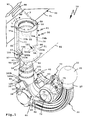
- a trailer coupling 10 shown in the drawing comprises a coupling arm 20 which is releasably securable to a vehicle mount 50.
- the coupling arm 20 has a plug-in projection 21 which can be inserted into a plug-in receptacle 52 of the vehicle mount 50.
- the vehicle mount 50 includes a housing, e.g. a sleeve 51 which limits the plug-in receptacle 52.
- the coupling arm 20 can be inserted or removed from the plug-in receptacle 52 along a plug-in axis S.
- a swivel-sliding bearing would be possible based on a schematically illustrated bearing 121, ie, for example, that the coupling arm 20 is pivotable about the pivot axis S and along this also displaceable with respect to the vehicle bracket 50.
- the coupling arm 20 is thus for example between an in FIG. 4 illustrated use position G and a non-use position N adjustable so that it is hidden behind a bumper 92 of a motor vehicle 90 when not in use, is at least substantially hidden.
- the vehicle mount 50 is attached, for example, to a cross member 91, which extends behind the motor vehicle 90, below a bumper 92 of the motor vehicle 90.
- the cross member 91 and, for example, this (not shown) to the body of the motor vehicle 90 side bolsters are components of a preferably belonging to the trailer hitch 10 support structure.
- a coupling body 22 for example, a coupling ball 23, respectively.
- An arm portion 24 of the coupling arm 20 between the male end of the coupling arm 20, the male projection 21, and the coupling body 22 is curved, for example, in a conventional manner.
- a contact unit holder 25 is provided which serves to hold a vehicle contact unit 70.
- the vehicle contact unit 70 is provided, for example, in accordance with DIN 1724 with 7 electrical connection contacts 71 or according to ISO 11446 with 13 electrical connection contacts 71, which are indicated schematically. However, the very specific embodiment of the vehicle contact unit 70 is not limited to these two standards, i. Other configurations, including proprietary embodiments, of the contact unit 70 may also be provided.
- a trailer contact unit 95 can be inserted, for example, a plurality of pins 96 or other plug contacts for insertion into receptacles of the vehicle contact unit 70, where the electrical connection contacts 71 are provided.
- the coupling arm 20 can be fixed and locked to the vehicle mount 50 by means of a fixing device 40.
- the fixing device 40 includes, for example, form-fitting projections 30, which engage in corresponding form-fitting receptacles 54 at the lower edge 53 of the vehicle mount 50 when the coupling arm 20 is fully inserted into the vehicle mount 50.
- the form-fitting receptacles 54 have, for example, obliquely mutually extending form-fitting surfaces 57, which also have inclined form-fitting surfaces 31 of the form-fitting projections 30 are in positive contact when the positive-fit projections 30 engage in the form-fitting receptacles 54.
- the form-fitting projections 30 and the form-fitting receptacles 54 are arranged, for example, at an angular distance of 180 ° to each other.
- the form-fitting receptacles 54 are V-shaped in side view, as are the mating form-fitting projections 30.
- the form-fitting surfaces 31, 57 can also be referred to as inclined surfaces or wedge surfaces which ensure a firm seating of the coupling arm 20 on the vehicle mount 50 in the use position G.
- the locking device has locking elements 41, e.g. Balls, which are actuated by an actuating body 42 radially outward from the plug projection 21 of the coupling arm 20 out so that they are pressed into a receptacle 55, for example in the manner of a ball trough or the like.
- locking elements 41 e.g. Balls
- an actuating body 42 radially outward from the plug projection 21 of the coupling arm 20 out so that they are pressed into a receptacle 55, for example in the manner of a ball trough or the like.
- the actuating body 42 for example, a so-called locking pin, is loaded by a spring, not shown, in the direction of the blocking position, in which the locking elements 41 are pressed into the receptacle 55, and can be based on a Handwheel 43 or any other operating mechanism ', manually or motorized are adjusted to a release position in which the locking elements 41 out of the receptacle 55 out and into the male projection 21 and there arranged channels can get into it.
- the sleeve 51 of the vehicle mount 50 is open at the top (opening 56), but could also be readily closed.
- the following explained electrical connection between on the one hand the vehicle mount 50 and on the other hand, the coupling arm 20 and the further connection with an electrical system 93 of the motor vehicle 90 are still possible.
- the electrical components are namely provided on the outside of the coupling arm 20 and, as far as possible, also on the outside of the vehicle mount 50, which makes even a subsequent mounting of the electrical system of the trailer coupling 10 readily possible.
- the vehicle contact unit 70 has, for example, a housing 72 which can be closed by a cover 73.
- the lid 73 is pivotally mounted on the housing 72, for example, by means of a pivot bearing 79. Behind the cover 73, which conceals a plug-in receptacle 74 of the vehicle contact unit 70 (which is shown in the drawing), the connection contacts 71, for example 7 or 13 connection contacts 71, are arranged.
- the connection contacts 71 are actuated by a control unit 75 which is integrated in the vehicle contact unit 70.
- the control unit 75 has, for example, a bus controller 76, which can be controlled via electrical bus lines 77 or communicates via electrical bus lines 77.
- the bus controller 76 forms a bus interface and at the same time also a serial interface of the vehicle contact unit 70.
- the bus that the bus controller 76 uses is a CAN bus or the like.
- bus served by the bus controller 76 need not necessarily be a bus common to motor vehicles, e.g. to a CAN or Flexray bus.
- a proprietary bus may also be provided, for example for communication with the later-described control unit 98, which is arranged on board the motor vehicle 90.
- control unit 75 is connected to two electrical supply lines 78, which supply the vehicle contact unit 70 with electrical energy.
- one supply line 78a has a ground potential MP
- the other supply line 78b has a supply potential P, e.g. 12 volts.
- the lines 77, 78 form cores or individual lines of a connecting line 80, which comprises a vehicle electrical system section 81 connected to the electrical system 93 and a contact unit section 82 connected to the vehicle contact unit 70.
- the sections 81, 82 each have the mentioned individual lines or wires, namely the lines 77a, 77b, 78a, 78b, which, however, are drawn individually only in the area of the electrical system section 81.
- the vehicle electrical system section 82 includes strands or sub-lines 83, 84, which include the lines 77a, 77b and 78a, 78b.
- the lines 83, 84 are in line channels 59 of the vehicle bracket 50 to the electrical system 93 or the control unit 98, which is so to speak directly integrated into the vehicle electrical system of the motor vehicle 90 out.
- the lines 83, 84 could also be free-guided lines or be accommodated in groove-shaped depressions, for example on the outer circumference, of the vehicle mount 50.
- the two sections 81, 82 are connected by contact elements 100, 101 and 150, 151 electrically releasably connectable to each other.
- the contact elements 100, 101 are connected to the contact unit section 82 and are located on the form-fitting contours 38 of the coupling arm 20.
- the contact elements 100, 101 are associated with the other contact elements 150, 151, in turn, on the vehicle mount 50, namely in the area the form-locking contours 58 are arranged.
- the contact element 100 has two contacts 102, namely a contact 102a connected to the bus line 77a and a contact 102b connected to the bus line 77b.
- the contact element 101 has contacts 103a and 103b which are connected to the supply lines 78a and 78b.
- the contact elements 150, 151 also each have 2 contacts, namely contacts 152a, 152b for the bus lines 77a and 77b and contacts 153a, 153b for the supply lines 78a and 78b.
- the contact elements 100, 101 have, for example, a housing or a holding body 104, on which the respective contacts 102 and 103 are arranged.
- the holding body 104 are for example made of plastic or other electrically insulating material.
- the contacts 102, 103 are preferably spring-loaded.
- the contacts 102, 103 are formed by resilient pins or pins.
- the springs are expediently arranged in the interior of the holding bodies 104. It is also possible that the contacts 102, 103 are configured, for example, as resilient contact lugs.
- the contacts 102, 103 consist for example of metal, in particular of a noble metal, which has lower oxidation tendencies.
- the contact elements 150, 151 may be provided, for example, on retaining bodies 154, for the receptacles 60, for example plug-in receptacles or the like, are provided on the vehicle mount 50.
- the contacts 152a, 152b and contacts 153a, 153b may be, for example, metal surfaces that are provided directly and unsprung on the holding bodies 154.
- the vehicle mount 50 in the region of the contacts 152a, 152b and contacts 153a, 153b is electrically insulating, in any case that the contacts are provided directly on the vehicle mount 50.
- the contacts 152a, 152b and / or the contacts 153a, 153b or also the contacts 102, 103 to be provided with electrical insulation so that they come into contact with the material or base body of the vehicle mount 50 or of the coupling arm 20 do not produce electrical conduction, this base are so isolated over.
- the contacts 102, 103 could also be provided integrally on the coupling arm 20 or its base body, which then in turn have a certain insulation against the base body.
- the strand 85 contains the bus lines 77 and the supply lines 78.
- a spout 87 is preferably provided, that is, the connection line 80 is guided laterally and protected by a spout 87 out of the housing 72.
- the lines 77, 78 are suitably sheathed, ie protected for example by a flexible hose jacket material.
- connection line 80 branches off at a branch 88, the two supply lines 78 being led further to the contact element 100 in the strand 86 formed thereby.
- the strands 85, 86 are preferably splash-proof. It is advantageous if the connecting line 80 is integrally guided into the respective contact element 100, 101, for example, protected there from water and other environmental influences by means of a weld, a spout or the like.
- the contact elements 100, 101 are received, for example, in plug-in holders 34 of the form-fitting projections 30.
- the plug-in supports 34 are, for example, the end regions of channels 35 which, for example, extend parallel to the plug-in axis S in the form-fitting projections 30. Through the channels 35 through the strands 85, 86, at least the electrical lines contained therein, the contact unit section 82 can be passed through.
- the contact elements 101, 100 may, for example, additionally be glued in the plug-in supports 34, latched or the like otherwise secured cohesively and / or positively.
- a plug-in mounting of the contact elements 100, 101 in the plug-in supports 34 is, for example, by arrows M in FIG. 3 indicated.
- the vehicle contact unit 70 is readily on the main body of the coupling arm 20, also retrofitted mountable.
- the contact unit holder 25 comprises two receiving eyelets or eyelets 29, which can be penetrated by screws (not shown), which also penetrate eyebolts 69 of the vehicle contact unit 70.
- the contact elements 100, 101 are arranged at apex regions 33 of the form-fitting projections 30.
- a vertex surface 32 between the inclined form-fitting surfaces 31 is not in direct contact with a bottom 61 of the form-fitting receptacles 54, where the opposing contact elements 150, 151 are arranged.
- the bottom 61 and the top surface 32 are thus not directly loaded by the form-locking contact of the form-fitting contours 58, 38.
Landscapes
- Engineering & Computer Science (AREA)
- Transportation (AREA)
- Mechanical Engineering (AREA)
- Details Of Connecting Devices For Male And Female Coupling (AREA)
Applications Claiming Priority (1)
| Application Number | Priority Date | Filing Date | Title |
|---|---|---|---|
| DE102014003185.3A DE102014003185A1 (de) | 2014-03-01 | 2014-03-01 | Anhängekupplung mit einer Fahrzeug-Kontakteinheit |
Publications (2)
| Publication Number | Publication Date |
|---|---|
| EP2913208A1 true EP2913208A1 (fr) | 2015-09-02 |
| EP2913208B1 EP2913208B1 (fr) | 2019-03-20 |
Family
ID=52577750
Family Applications (1)
| Application Number | Title | Priority Date | Filing Date |
|---|---|---|---|
| EP15156708.8A Active EP2913208B1 (fr) | 2014-03-01 | 2015-02-26 | Attelage doté d'une unité de contact de véhicule |
Country Status (2)
| Country | Link |
|---|---|
| EP (1) | EP2913208B1 (fr) |
| DE (1) | DE102014003185A1 (fr) |
Cited By (3)
| Publication number | Priority date | Publication date | Assignee | Title |
|---|---|---|---|---|
| WO2018045037A1 (fr) * | 2016-08-30 | 2018-03-08 | Horizon Global Americas Inc. | Récepteur détachable |
| US20200180373A1 (en) * | 2018-12-06 | 2020-06-11 | Midway Products Group, Inc. | Hitch assembly |
| EP4134253A1 (fr) * | 2021-08-13 | 2023-02-15 | ACPS Automotive GmbH | Crochet d'attelage |
Citations (8)
| Publication number | Priority date | Publication date | Assignee | Title |
|---|---|---|---|---|
| EP0747244A1 (fr) * | 1995-06-07 | 1996-12-11 | Netherlands Car B.V. | Dispositif d'attelage pour atteler une remorque à un véhicule tracteur, partie de véhicule et partie de remorque convenant pour un tel dispositif d'attelage |
| EP0950549A1 (fr) * | 1998-04-17 | 1999-10-20 | Ellebi S.r.l. | Dispositif de remorquage d'un véhicule avec un accouplement à rotule amovible et verrouillage automatique, comportant une prise de courant |
| GB2363262A (en) * | 2000-06-09 | 2001-12-12 | Seat Sa | Removable tow-hitch and electrical connector |
| DE10027571A1 (de) | 2000-06-02 | 2001-12-13 | Oris Fahrzeugteile Riehle H | Anhängevorrichtung |
| EP1757488A2 (fr) * | 2005-08-25 | 2007-02-28 | WESTFALIA - Automotive GmbH | Structure de support pour véhicule et esemble support correspondant |
| WO2007091222A1 (fr) * | 2006-02-10 | 2007-08-16 | Jakobus Nikolaas Steenkamp | Attelage de remorque |
| EP2199118A1 (fr) | 2008-11-20 | 2010-06-23 | Ing. Plini e Gigliotti S.R.L. | Attelage |
| EP2428404A1 (fr) * | 2010-09-13 | 2012-03-14 | WESTFALIA - Automotive GmbH | Système de support de charges |
Family Cites Families (1)
| Publication number | Priority date | Publication date | Assignee | Title |
|---|---|---|---|---|
| DE102007060529A1 (de) * | 2007-12-13 | 2009-06-18 | Westfalia-Automotive Gmbh | Anhängekupplung mit Einführhilfeeinrichtung |
-
2014
- 2014-03-01 DE DE102014003185.3A patent/DE102014003185A1/de not_active Withdrawn
-
2015
- 2015-02-26 EP EP15156708.8A patent/EP2913208B1/fr active Active
Patent Citations (8)
| Publication number | Priority date | Publication date | Assignee | Title |
|---|---|---|---|---|
| EP0747244A1 (fr) * | 1995-06-07 | 1996-12-11 | Netherlands Car B.V. | Dispositif d'attelage pour atteler une remorque à un véhicule tracteur, partie de véhicule et partie de remorque convenant pour un tel dispositif d'attelage |
| EP0950549A1 (fr) * | 1998-04-17 | 1999-10-20 | Ellebi S.r.l. | Dispositif de remorquage d'un véhicule avec un accouplement à rotule amovible et verrouillage automatique, comportant une prise de courant |
| DE10027571A1 (de) | 2000-06-02 | 2001-12-13 | Oris Fahrzeugteile Riehle H | Anhängevorrichtung |
| GB2363262A (en) * | 2000-06-09 | 2001-12-12 | Seat Sa | Removable tow-hitch and electrical connector |
| EP1757488A2 (fr) * | 2005-08-25 | 2007-02-28 | WESTFALIA - Automotive GmbH | Structure de support pour véhicule et esemble support correspondant |
| WO2007091222A1 (fr) * | 2006-02-10 | 2007-08-16 | Jakobus Nikolaas Steenkamp | Attelage de remorque |
| EP2199118A1 (fr) | 2008-11-20 | 2010-06-23 | Ing. Plini e Gigliotti S.R.L. | Attelage |
| EP2428404A1 (fr) * | 2010-09-13 | 2012-03-14 | WESTFALIA - Automotive GmbH | Système de support de charges |
Cited By (8)
| Publication number | Priority date | Publication date | Assignee | Title |
|---|---|---|---|---|
| WO2018045037A1 (fr) * | 2016-08-30 | 2018-03-08 | Horizon Global Americas Inc. | Récepteur détachable |
| CN109890631A (zh) * | 2016-08-30 | 2019-06-14 | 地平线全球美洲股份有限公司 | 可拆卸接收器 |
| US10836225B2 (en) | 2016-08-30 | 2020-11-17 | Horizon Global Americas Inc. | Detachable receiver |
| US11752817B2 (en) | 2016-08-30 | 2023-09-12 | Horizon Global Americas Inc. | Detachable receiver |
| CN109890631B (zh) * | 2016-08-30 | 2023-10-31 | 地平线全球美洲股份有限公司 | 可拆卸接收器 |
| US20200180373A1 (en) * | 2018-12-06 | 2020-06-11 | Midway Products Group, Inc. | Hitch assembly |
| US11679636B2 (en) * | 2018-12-06 | 2023-06-20 | Midway Products Group, Inc. | Hitch assembly |
| EP4134253A1 (fr) * | 2021-08-13 | 2023-02-15 | ACPS Automotive GmbH | Crochet d'attelage |
Also Published As
| Publication number | Publication date |
|---|---|
| EP2913208B1 (fr) | 2019-03-20 |
| DE102014003185A1 (de) | 2015-09-03 |
Similar Documents
| Publication | Publication Date | Title |
|---|---|---|
| DE19815843B4 (de) | Vorrichtung zur Energie- und Signalübertragung zischen Teilen eines Fahrzeugs | |
| EP1824691B1 (fr) | Système servant à connecter des lignes d'alimentation | |
| DE102014108071A1 (de) | Anhängekupplung | |
| DE102012105857B4 (de) | Anhängeeinrichtung-Aufnahme-Vorrichtung für Fahrzeug | |
| EP3113294B1 (fr) | Systeme de connexion par fiche pour le raccordement electrique d'une remorque a un vehicule tracteur | |
| DE202016105321U1 (de) | Rangierantriebssystem sowie Fahrzeug mit einem solchen | |
| EP2070311A1 (fr) | Systeme de camera modulaire | |
| EP2913208B1 (fr) | Attelage doté d'une unité de contact de véhicule | |
| EP3034335B1 (fr) | Attelage | |
| DE10021232B4 (de) | Anhängerkupplung | |
| DE102012004345A1 (de) | Kupplungssteuervorrichtung und damit ausgestattete Anhängekupplung | |
| DE102018132867A1 (de) | Steckverbindervorrichtung für ein Fahrzeug zum Übertragen von Daten zwischen gekuppelten Fahrzeugen sowie System und Fahrzeug damit | |
| DE10027571A1 (de) | Anhängevorrichtung | |
| DE102019207384B4 (de) | Induktive elektrische Energieübertragung zwischen einem Zugfahrzeug und einem gezogenen Fahrzeug | |
| DE4235539B4 (de) | Schleppzug, insbesondere Sattelzug | |
| EP3466728B1 (fr) | Dispositif d'attelage pour un véhicule automobile | |
| DE102010051584A1 (de) | Schaltungsanordnung in einem Zugfahrzeug sowie einem Anhänger | |
| DE202021106965U1 (de) | Steckverbinder für eine kombinierte elektrische Verbindung und Datenverbindung | |
| DE102017221574A1 (de) | Batteriestecker-Betätigungssystem | |
| DE102015122424A1 (de) | Verfahren zum Erfassen eines Umgebungsbereichs eines Gespanns mit einem Kraftfahrzeug und einem Anhänger sowie Kamerasystem | |
| DE102016015048A1 (de) | Halteanordnung zur lösbaren Halterung eines elektrischen Geräts im Innenraum eines Kraftfahrzeugs | |
| DE102008044941A1 (de) | Stromversorgungseinrichtung für ein auflaufgebremstes Anhängerfahrzeug | |
| DE102009050932A1 (de) | Anhängerkupplungseinrichtung für einen Kraftwagen | |
| DE10308078A1 (de) | Vorrichtung zum Übertragen von Signalen und/oder Energie | |
| EP0762561B1 (fr) | Conducteur électrique notamment pour l'utilisation dans des véhicules |
Legal Events
| Date | Code | Title | Description |
|---|---|---|---|
| PUAI | Public reference made under article 153(3) epc to a published international application that has entered the european phase |
Free format text: ORIGINAL CODE: 0009012 |
|
| AK | Designated contracting states |
Kind code of ref document: A1 Designated state(s): AL AT BE BG CH CY CZ DE DK EE ES FI FR GB GR HR HU IE IS IT LI LT LU LV MC MK MT NL NO PL PT RO RS SE SI SK SM TR |
|
| AX | Request for extension of the european patent |
Extension state: BA ME |
|
| 17P | Request for examination filed |
Effective date: 20160226 |
|
| RBV | Designated contracting states (corrected) |
Designated state(s): AL AT BE BG CH CY CZ DE DK EE ES FI FR GB GR HR HU IE IS IT LI LT LU LV MC MK MT NL NO PL PT RO RS SE SI SK SM TR |
|
| GRAP | Despatch of communication of intention to grant a patent |
Free format text: ORIGINAL CODE: EPIDOSNIGR1 |
|
| STAA | Information on the status of an ep patent application or granted ep patent |
Free format text: STATUS: GRANT OF PATENT IS INTENDED |
|
| INTG | Intention to grant announced |
Effective date: 20181012 |
|
| GRAS | Grant fee paid |
Free format text: ORIGINAL CODE: EPIDOSNIGR3 |
|
| GRAA | (expected) grant |
Free format text: ORIGINAL CODE: 0009210 |
|
| STAA | Information on the status of an ep patent application or granted ep patent |
Free format text: STATUS: THE PATENT HAS BEEN GRANTED |
|
| AK | Designated contracting states |
Kind code of ref document: B1 Designated state(s): AL AT BE BG CH CY CZ DE DK EE ES FI FR GB GR HR HU IE IS IT LI LT LU LV MC MK MT NL NO PL PT RO RS SE SI SK SM TR |
|
| REG | Reference to a national code |
Ref country code: GB Ref legal event code: FG4D Free format text: NOT ENGLISH |
|
| REG | Reference to a national code |
Ref country code: CH Ref legal event code: EP |
|
| REG | Reference to a national code |
Ref country code: DE Ref legal event code: R096 Ref document number: 502015008381 Country of ref document: DE |
|
| REG | Reference to a national code |
Ref country code: AT Ref legal event code: REF Ref document number: 1110162 Country of ref document: AT Kind code of ref document: T Effective date: 20190415 |
|
| REG | Reference to a national code |
Ref country code: IE Ref legal event code: FG4D Free format text: LANGUAGE OF EP DOCUMENT: GERMAN |
|
| REG | Reference to a national code |
Ref country code: NL Ref legal event code: MP Effective date: 20190320 |
|
| PG25 | Lapsed in a contracting state [announced via postgrant information from national office to epo] |
Ref country code: FI Free format text: LAPSE BECAUSE OF FAILURE TO SUBMIT A TRANSLATION OF THE DESCRIPTION OR TO PAY THE FEE WITHIN THE PRESCRIBED TIME-LIMIT Effective date: 20190320 Ref country code: NO Free format text: LAPSE BECAUSE OF FAILURE TO SUBMIT A TRANSLATION OF THE DESCRIPTION OR TO PAY THE FEE WITHIN THE PRESCRIBED TIME-LIMIT Effective date: 20190620 Ref country code: SE Free format text: LAPSE BECAUSE OF FAILURE TO SUBMIT A TRANSLATION OF THE DESCRIPTION OR TO PAY THE FEE WITHIN THE PRESCRIBED TIME-LIMIT Effective date: 20190320 Ref country code: LT Free format text: LAPSE BECAUSE OF FAILURE TO SUBMIT A TRANSLATION OF THE DESCRIPTION OR TO PAY THE FEE WITHIN THE PRESCRIBED TIME-LIMIT Effective date: 20190320 |
|
| REG | Reference to a national code |
Ref country code: LT Ref legal event code: MG4D |
|
| PG25 | Lapsed in a contracting state [announced via postgrant information from national office to epo] |
Ref country code: RS Free format text: LAPSE BECAUSE OF FAILURE TO SUBMIT A TRANSLATION OF THE DESCRIPTION OR TO PAY THE FEE WITHIN THE PRESCRIBED TIME-LIMIT Effective date: 20190320 Ref country code: GR Free format text: LAPSE BECAUSE OF FAILURE TO SUBMIT A TRANSLATION OF THE DESCRIPTION OR TO PAY THE FEE WITHIN THE PRESCRIBED TIME-LIMIT Effective date: 20190621 Ref country code: HR Free format text: LAPSE BECAUSE OF FAILURE TO SUBMIT A TRANSLATION OF THE DESCRIPTION OR TO PAY THE FEE WITHIN THE PRESCRIBED TIME-LIMIT Effective date: 20190320 Ref country code: NL Free format text: LAPSE BECAUSE OF FAILURE TO SUBMIT A TRANSLATION OF THE DESCRIPTION OR TO PAY THE FEE WITHIN THE PRESCRIBED TIME-LIMIT Effective date: 20190320 Ref country code: LV Free format text: LAPSE BECAUSE OF FAILURE TO SUBMIT A TRANSLATION OF THE DESCRIPTION OR TO PAY THE FEE WITHIN THE PRESCRIBED TIME-LIMIT Effective date: 20190320 Ref country code: BG Free format text: LAPSE BECAUSE OF FAILURE TO SUBMIT A TRANSLATION OF THE DESCRIPTION OR TO PAY THE FEE WITHIN THE PRESCRIBED TIME-LIMIT Effective date: 20190620 |
|
| PG25 | Lapsed in a contracting state [announced via postgrant information from national office to epo] |
Ref country code: SK Free format text: LAPSE BECAUSE OF FAILURE TO SUBMIT A TRANSLATION OF THE DESCRIPTION OR TO PAY THE FEE WITHIN THE PRESCRIBED TIME-LIMIT Effective date: 20190320 Ref country code: RO Free format text: LAPSE BECAUSE OF FAILURE TO SUBMIT A TRANSLATION OF THE DESCRIPTION OR TO PAY THE FEE WITHIN THE PRESCRIBED TIME-LIMIT Effective date: 20190320 Ref country code: EE Free format text: LAPSE BECAUSE OF FAILURE TO SUBMIT A TRANSLATION OF THE DESCRIPTION OR TO PAY THE FEE WITHIN THE PRESCRIBED TIME-LIMIT Effective date: 20190320 Ref country code: IT Free format text: LAPSE BECAUSE OF FAILURE TO SUBMIT A TRANSLATION OF THE DESCRIPTION OR TO PAY THE FEE WITHIN THE PRESCRIBED TIME-LIMIT Effective date: 20190320 Ref country code: PT Free format text: LAPSE BECAUSE OF FAILURE TO SUBMIT A TRANSLATION OF THE DESCRIPTION OR TO PAY THE FEE WITHIN THE PRESCRIBED TIME-LIMIT Effective date: 20190720 Ref country code: ES Free format text: LAPSE BECAUSE OF FAILURE TO SUBMIT A TRANSLATION OF THE DESCRIPTION OR TO PAY THE FEE WITHIN THE PRESCRIBED TIME-LIMIT Effective date: 20190320 Ref country code: AL Free format text: LAPSE BECAUSE OF FAILURE TO SUBMIT A TRANSLATION OF THE DESCRIPTION OR TO PAY THE FEE WITHIN THE PRESCRIBED TIME-LIMIT Effective date: 20190320 Ref country code: CZ Free format text: LAPSE BECAUSE OF FAILURE TO SUBMIT A TRANSLATION OF THE DESCRIPTION OR TO PAY THE FEE WITHIN THE PRESCRIBED TIME-LIMIT Effective date: 20190320 |
|
| PG25 | Lapsed in a contracting state [announced via postgrant information from national office to epo] |
Ref country code: SM Free format text: LAPSE BECAUSE OF FAILURE TO SUBMIT A TRANSLATION OF THE DESCRIPTION OR TO PAY THE FEE WITHIN THE PRESCRIBED TIME-LIMIT Effective date: 20190320 Ref country code: PL Free format text: LAPSE BECAUSE OF FAILURE TO SUBMIT A TRANSLATION OF THE DESCRIPTION OR TO PAY THE FEE WITHIN THE PRESCRIBED TIME-LIMIT Effective date: 20190320 |
|
| PG25 | Lapsed in a contracting state [announced via postgrant information from national office to epo] |
Ref country code: IS Free format text: LAPSE BECAUSE OF FAILURE TO SUBMIT A TRANSLATION OF THE DESCRIPTION OR TO PAY THE FEE WITHIN THE PRESCRIBED TIME-LIMIT Effective date: 20190720 |
|
| REG | Reference to a national code |
Ref country code: DE Ref legal event code: R097 Ref document number: 502015008381 Country of ref document: DE |
|
| PLBE | No opposition filed within time limit |
Free format text: ORIGINAL CODE: 0009261 |
|
| STAA | Information on the status of an ep patent application or granted ep patent |
Free format text: STATUS: NO OPPOSITION FILED WITHIN TIME LIMIT |
|
| PG25 | Lapsed in a contracting state [announced via postgrant information from national office to epo] |
Ref country code: DK Free format text: LAPSE BECAUSE OF FAILURE TO SUBMIT A TRANSLATION OF THE DESCRIPTION OR TO PAY THE FEE WITHIN THE PRESCRIBED TIME-LIMIT Effective date: 20190320 |
|
| 26N | No opposition filed |
Effective date: 20200102 |
|
| PG25 | Lapsed in a contracting state [announced via postgrant information from national office to epo] |
Ref country code: SI Free format text: LAPSE BECAUSE OF FAILURE TO SUBMIT A TRANSLATION OF THE DESCRIPTION OR TO PAY THE FEE WITHIN THE PRESCRIBED TIME-LIMIT Effective date: 20190320 |
|
| PG25 | Lapsed in a contracting state [announced via postgrant information from national office to epo] |
Ref country code: TR Free format text: LAPSE BECAUSE OF FAILURE TO SUBMIT A TRANSLATION OF THE DESCRIPTION OR TO PAY THE FEE WITHIN THE PRESCRIBED TIME-LIMIT Effective date: 20190320 |
|
| REG | Reference to a national code |
Ref country code: CH Ref legal event code: PL |
|
| GBPC | Gb: european patent ceased through non-payment of renewal fee |
Effective date: 20200226 |
|
| REG | Reference to a national code |
Ref country code: BE Ref legal event code: MM Effective date: 20200229 |
|
| PG25 | Lapsed in a contracting state [announced via postgrant information from national office to epo] |
Ref country code: LU Free format text: LAPSE BECAUSE OF NON-PAYMENT OF DUE FEES Effective date: 20200226 Ref country code: MC Free format text: LAPSE BECAUSE OF FAILURE TO SUBMIT A TRANSLATION OF THE DESCRIPTION OR TO PAY THE FEE WITHIN THE PRESCRIBED TIME-LIMIT Effective date: 20190320 |
|
| PG25 | Lapsed in a contracting state [announced via postgrant information from national office to epo] |
Ref country code: CH Free format text: LAPSE BECAUSE OF NON-PAYMENT OF DUE FEES Effective date: 20200229 Ref country code: LI Free format text: LAPSE BECAUSE OF NON-PAYMENT OF DUE FEES Effective date: 20200229 |
|
| PG25 | Lapsed in a contracting state [announced via postgrant information from national office to epo] |
Ref country code: GB Free format text: LAPSE BECAUSE OF NON-PAYMENT OF DUE FEES Effective date: 20200226 Ref country code: IE Free format text: LAPSE BECAUSE OF NON-PAYMENT OF DUE FEES Effective date: 20200226 |
|
| PG25 | Lapsed in a contracting state [announced via postgrant information from national office to epo] |
Ref country code: BE Free format text: LAPSE BECAUSE OF NON-PAYMENT OF DUE FEES Effective date: 20200229 |
|
| REG | Reference to a national code |
Ref country code: AT Ref legal event code: MM01 Ref document number: 1110162 Country of ref document: AT Kind code of ref document: T Effective date: 20200226 |
|
| PG25 | Lapsed in a contracting state [announced via postgrant information from national office to epo] |
Ref country code: AT Free format text: LAPSE BECAUSE OF NON-PAYMENT OF DUE FEES Effective date: 20200226 |
|
| PG25 | Lapsed in a contracting state [announced via postgrant information from national office to epo] |
Ref country code: MT Free format text: LAPSE BECAUSE OF FAILURE TO SUBMIT A TRANSLATION OF THE DESCRIPTION OR TO PAY THE FEE WITHIN THE PRESCRIBED TIME-LIMIT Effective date: 20190320 Ref country code: CY Free format text: LAPSE BECAUSE OF FAILURE TO SUBMIT A TRANSLATION OF THE DESCRIPTION OR TO PAY THE FEE WITHIN THE PRESCRIBED TIME-LIMIT Effective date: 20190320 |
|
| PGFP | Annual fee paid to national office [announced via postgrant information from national office to epo] |
Ref country code: FR Payment date: 20220113 Year of fee payment: 8 |
|
| PG25 | Lapsed in a contracting state [announced via postgrant information from national office to epo] |
Ref country code: MK Free format text: LAPSE BECAUSE OF FAILURE TO SUBMIT A TRANSLATION OF THE DESCRIPTION OR TO PAY THE FEE WITHIN THE PRESCRIBED TIME-LIMIT Effective date: 20190320 |
|
| PG25 | Lapsed in a contracting state [announced via postgrant information from national office to epo] |
Ref country code: FR Free format text: LAPSE BECAUSE OF NON-PAYMENT OF DUE FEES Effective date: 20230228 |
|
| PGFP | Annual fee paid to national office [announced via postgrant information from national office to epo] |
Ref country code: DE Payment date: 20240228 Year of fee payment: 10 |