EP2913208A1 - Tow bar with a vehicle contact unit - Google Patents
Tow bar with a vehicle contact unit Download PDFInfo
- Publication number
- EP2913208A1 EP2913208A1 EP15156708.8A EP15156708A EP2913208A1 EP 2913208 A1 EP2913208 A1 EP 2913208A1 EP 15156708 A EP15156708 A EP 15156708A EP 2913208 A1 EP2913208 A1 EP 2913208A1
- Authority
- EP
- European Patent Office
- Prior art keywords
- contact
- vehicle
- electrical
- trailer
- coupling arm
- Prior art date
- Legal status (The legal status is an assumption and is not a legal conclusion. Google has not performed a legal analysis and makes no representation as to the accuracy of the status listed.)
- Granted
Links
- 230000008878 coupling Effects 0.000 claims abstract description 121
- 238000010168 coupling process Methods 0.000 claims abstract description 121
- 238000005859 coupling reaction Methods 0.000 claims abstract description 121
- 238000004891 communication Methods 0.000 claims description 8
- 229910052751 metal Inorganic materials 0.000 claims description 4
- 239000002184 metal Substances 0.000 claims description 4
- 230000013011 mating Effects 0.000 claims description 2
- 230000005540 biological transmission Effects 0.000 claims 1
- 238000004519 manufacturing process Methods 0.000 description 4
- 238000009420 retrofitting Methods 0.000 description 3
- XEEYBQQBJWHFJM-UHFFFAOYSA-N Iron Chemical compound [Fe] XEEYBQQBJWHFJM-UHFFFAOYSA-N 0.000 description 2
- 230000008901 benefit Effects 0.000 description 2
- 238000005516 engineering process Methods 0.000 description 2
- 238000003780 insertion Methods 0.000 description 2
- 230000037431 insertion Effects 0.000 description 2
- 238000009413 insulation Methods 0.000 description 2
- 239000000463 material Substances 0.000 description 2
- 230000007246 mechanism Effects 0.000 description 2
- 230000003647 oxidation Effects 0.000 description 2
- 238000007254 oxidation reaction Methods 0.000 description 2
- 241001236644 Lavinia Species 0.000 description 1
- 229910000831 Steel Inorganic materials 0.000 description 1
- 238000004026 adhesive bonding Methods 0.000 description 1
- 229910052782 aluminium Inorganic materials 0.000 description 1
- XAGFODPZIPBFFR-UHFFFAOYSA-N aluminium Chemical compound [Al] XAGFODPZIPBFFR-UHFFFAOYSA-N 0.000 description 1
- 230000009286 beneficial effect Effects 0.000 description 1
- 230000000903 blocking effect Effects 0.000 description 1
- 238000005266 casting Methods 0.000 description 1
- 238000010292 electrical insulation Methods 0.000 description 1
- 239000012777 electrically insulating material Substances 0.000 description 1
- 230000007613 environmental effect Effects 0.000 description 1
- 238000005242 forging Methods 0.000 description 1
- 229910052742 iron Inorganic materials 0.000 description 1
- 238000000034 method Methods 0.000 description 1
- 238000012544 monitoring process Methods 0.000 description 1
- 229910000510 noble metal Inorganic materials 0.000 description 1
- 230000008569 process Effects 0.000 description 1
- 238000012545 processing Methods 0.000 description 1
- 239000010959 steel Substances 0.000 description 1
- 238000003860 storage Methods 0.000 description 1
- XLYOFNOQVPJJNP-UHFFFAOYSA-N water Substances O XLYOFNOQVPJJNP-UHFFFAOYSA-N 0.000 description 1
Images


Classifications
-
- B—PERFORMING OPERATIONS; TRANSPORTING
- B60—VEHICLES IN GENERAL
- B60D—VEHICLE CONNECTIONS
- B60D1/00—Traction couplings; Hitches; Draw-gear; Towing devices
- B60D1/58—Auxiliary devices
- B60D1/62—Auxiliary devices involving supply lines, electric circuits, or the like
- B60D1/64—Couplings or joints therefor
-
- B—PERFORMING OPERATIONS; TRANSPORTING
- B60—VEHICLES IN GENERAL
- B60D—VEHICLE CONNECTIONS
- B60D1/00—Traction couplings; Hitches; Draw-gear; Towing devices
- B60D1/01—Traction couplings or hitches characterised by their type
- B60D1/06—Ball-and-socket hitches, e.g. constructional details, auxiliary devices, their arrangement on the vehicle
-
- B—PERFORMING OPERATIONS; TRANSPORTING
- B60—VEHICLES IN GENERAL
- B60D—VEHICLE CONNECTIONS
- B60D1/00—Traction couplings; Hitches; Draw-gear; Towing devices
- B60D1/48—Traction couplings; Hitches; Draw-gear; Towing devices characterised by the mounting
- B60D1/52—Traction couplings; Hitches; Draw-gear; Towing devices characterised by the mounting removably mounted
-
- B—PERFORMING OPERATIONS; TRANSPORTING
- B60—VEHICLES IN GENERAL
- B60D—VEHICLE CONNECTIONS
- B60D1/00—Traction couplings; Hitches; Draw-gear; Towing devices
- B60D1/48—Traction couplings; Hitches; Draw-gear; Towing devices characterised by the mounting
- B60D1/54—Traction couplings; Hitches; Draw-gear; Towing devices characterised by the mounting collapsible or retractable when not in use, e.g. hide-away hitches
Definitions
- the invention relates to a towing hitch for a motor vehicle, with a coupling arm for coupling a trailer or a rear load carrier which protrudes in a position of use to the rear in front of the motor vehicle, wherein the coupling arm on a fastened to the motor vehicle or vehicle mount based on a male projection and a plug-in receptacle releasably attachable or mounted on the basis of a bearing between the use position and a closer to the motor vehicle off-set position, wherein the hitch has a fixing device for fixing the coupling arm to the vehicle mount, in which on the vehicle mount and the coupling arm next to the male projection and the plug-in receptacle or arranged next to the bearing positive locking contours interlocking with each other, wherein on the coupling arm, an electrical vehicle-contact unit with electrical connection contacts to elec trischen connection of an electric trailer contact unit of the trailer is arranged, which has at least one electrical connection line for connection to an electrical system of the motor vehicle.
- a coupling arm of a trailer coupling is at least in the position of use usually determined form-fitting contours with respect to the vehicle mount and thus secured. It is now also common that a socket on the coupling arm is arranged directly so that it is easily accessible when using the hitch.
- Such embodiments are in both so-called pivot systems, ie in trailer hitches, the coupling arm between a use position and a non-use position usually swivel, in some cases axially displaceable is stored.
- plug-in systems ie, for example, according to EP 2 199 118 A1 or DE 100 27 571 A1 It is known to arrange the socket, thus the vehicle contact unit, directly on the coupling arm.
- the production of electrical connections from the vehicle to an arranged on the coupling arm socket is relatively difficult to implement. For example, it requires sufficiently flexible cables (in the case of the aforementioned pivoting systems) or complicated electrical plug-in contact systems.
- electrical contact elements are arranged on the positive locking contours, which are in the use position of the coupling arm in contact with each other and provided for connection to the electrical system wiring system section and one with the vehicle Contact unit connected contact unit section of at least one electrical connection line with each other.
- the vehicle contact unit is, for example, a trailer socket, in particular a DIN-compliant or standard-compliant trailer socket.
- the vehicle contact unit is configured, for example, according to a European or German standard. For example, It has 7 contacts according to DIN 1724 or 13 contacts according to ISO 11446, for establishing an electrical connection with the trailer contact unit, ie a matching trailer plug.
- the vehicle contact unit is arranged in a manner known per se on the coupling arm, but the electrical contact outside of the bearing, with which the coupling arm between the use position and the non-use position movably mounted is, for example, pivotable about a pivot axis and / or slidably about a control axis (wherein the adjusting axis may be simultaneously the pivot axis), is provided.
- the usual in so-called plug-in systems connector between the coupling arm and vehicle mount is free of electrical contact elements.
- One advantage is that the connection mechanism between the vehicle mount and the coupling arm is not affected by the electrical components. You do not need to increase the space for the electrical connection between the vehicle bracket and coupling arm. Rather, the electrical contact takes place outside of this connection technology, namely the positive locking contours.
- the inventive concept is optimally suited for retrofitting, i. for example, a trailer hitch with a conventional one adjacent to the vehicle mount, e.g. On the cross member, arranged socket can be converted to a trailer hitch with socket (vehicle contact unit) directly on the coupling arm.
- the electrical connection technology namely the aforementioned contact elements, can be retrofitted so to speak in the region of the form-fitting contours. Also, a series production is simplified or implemented a common part principle.
- At least one contact element is required, which is electrically isolated from the base bodies of the vehicle mount and the coupling arm, while the other potential, for example a ground potential, can also be realized by the direct contact of the coupling arm with the vehicle mount.
- the main body of the vehicle mount and the coupling arm may constitute a contact element, while the other contact element is electrically isolated therefrom and transmits, for example, a supply potential for the vehicle contact unit.
- the contact elements are preferably not in direct force-loaded or positively acted on area of the positive locking contours.
- An advantageous embodiment of the invention provides that the contact elements are arranged next to in the position of use in contact with each other standing form-fitting surfaces of the form-fitting contours, so that the contact elements are unloaded by the positive contact of the form-fitting contours. Nevertheless, in the region of the form-fitting contours defined distances between on the one hand the coupling arm and the other hand, the vehicle mount so that the contact elements are optimally positioned to each other when the coupling arm occupies the position of use.
- the form-fitting contours can have any shape per se. It is conceivable, for example, that the form-fitting contours are undulating, V-shaped or the like. Also interengaging plug-in projections and plug-in receptacles, for example in the form of bolts and cylindrical plug receptacles or the like, may be provided in the manner according to the invention with one or more contact elements.
- a preferred embodiment of the invention provides that the form-fitting contours comprise at least one groove-shaped form-fitting receptacle and at least one matching form-fitting projection.
- positive locking receptacle and form-fitting projection are V-shaped or U-shaped. But also a rectangular in the side view shape is readily possible, that is, for example, the positive locking projection is bolt-like, while the positive locking receptacle is cylindrical, for example, includes a blind hole.
- a pairing consisting of a first and a second contact element of the arrangement of, for example, further contact elements are arranged opposite each other at a bottom of the at least one positive connection receptacle and a vertex area or frontal area, in particular on a free end face, of the at least one positive locking projection.
- the apex region or end region of the form-fitting projection is at the bottom of the positive-fit receptacle opposite, so that the two cooperating contact elements make electrical contact with each other.
- a respective contact element may have, for example, one or more electrical contact surfaces.
- the contact surfaces may have any contours, for example, be annular, rectangular or circular or the like.
- a respective contact element has a plurality of electrically isolated contact surfaces, for example, two or three contact surfaces.
- a contact element preferably has an electrically insulating holding body, e.g. made of plastic, and at least one electrical contact arranged thereon, for example a flat contact or a punctiform contact.
- the respective contact surfaces may be unsprung or, in a preferred embodiment, spring-loaded.
- a non-sprung, not in the direction of the opposite contact surfaces of the other contact element so to speak of self-moving contact surface is opposite a resilient contact surface or a spring contact.
- a plug-in holder for attaching at least one of the contact elements.
- a plug-in receptacle for inserting the respective contact element is provided.
- the plug-in receptacle may for example have a receiving channel, in which the contact element is inserted, so to speak.
- a mounting space for the respective contact element on the coupling arm or the vehicle mount is provided.
- an additional safety measure for example, a screw, gluing or the like, it is possible to secure the contact element to the plug-in holder.
- a contact unit holder for holding the vehicle contact unit is expediently provided on the coupling arm.
- the contact unit holder has e.g. in front of an arm body of the coupling arm projecting mounting tabs and / or mounting lugs or the like.
- the contact unit holder may also include a plug-in receptacle or the like for receiving the vehicle contact unit.
- a conduit for receiving at least a portion of the at least one connecting line can be arranged on the coupling arm or the vehicle mount or both.
- the duct or a portion thereof may be, for example, a tubular, i. act in the circumference closed, duct.
- a laterally open wiring, e.g. a groove-shaped channel is advantageous in the duct or a portion thereof.
- the plug-in holder or the contact unit holder or the conduit are expediently integral with a main body of the coupling arm or the vehicle holder.
- cutouts are provided.
- the main body of the coupling arm or the vehicle mount as a forging and / or casting the aforementioned components or configurations can be made, so to speak, the same with the respective basic coupling arm or the basic vehicle mount.
- a main body of the coupling arm and / or the vehicle mount is preferably made of metal, for example steel, iron, aluminum or the like.
- the contact unit section of the at least one connecting line expediently extends on an outer circumference of the coupling arm. It is also possible that two or more contact elements are each connected to the contact unit section, ie, that the contact unit section branches, for example, to the contact elements. Furthermore, it is possible that the Connecting lead from a first contact element leads to a second contact element, for example, with fewer wires or individual strands between the contact elements as to the first contact element.
- the hitch has two mutually arranged at an angular distance pairings of form-fitting contours, on each of which at least one pair of cooperating contact elements are provided.
- the distance between the pairings of form-fitting elements is for example 180 °, 120 ° or the like.
- the positive-locking contours could be arranged around the plug-in receptacle of the vehicle mount and correspondingly around the plug-in projection of the coupling arm. It is possible that all pairings of form-fitting contours are provided with associated pairings of contact elements. But it is also possible that there are pairings of form-fitting contours on which no cooperating pairings of contact elements are provided.
- the plug-in receptacle is preferably provided in the vehicle mount, the plug-in projection in the coupling arm.
- the vehicle mount can have a plug-in projection and the coupling arm can have a plug-in receptacle.
- control device for controlling the connection contacts of the vehicle contact unit.
- the controller may form part of a system that also includes the hitch.
- control unit may be a component of a kit which, in addition to the control unit, also includes the vehicle mount and the coupling arm as well as any connecting elements (plug connection, bearing or the like) arranged therebetween.
- the at least one connecting line, the contact elements and the vehicle contact unit may for example be part of an electrical kit.
- the electrical kit can be provided in the production of the trailer coupling or subsequently, so to speak for retrofitting the trailer coupling.
- control unit is on the vehicle side, so to speak. that it is located, for example, in the luggage compartment of the towing vehicle or motor vehicle, directly at the vehicle mount, e.g. on a cross member, or the like.
- connection cable with its electrical system section is connected to the control unit or connectable.
- the control unit forms a component of the vehicle contact unit. It is also possible that the controller is split, so to speak, i. a control device component is arranged on or in the motor vehicle, while the other control device component forms part of the vehicle contact unit.
- the control unit or the control unit component arranged in the vehicle contact unit or, for example, may comprise a bus coupler, so that the various connection contacts of the vehicle contact unit can be actuated via, for example, a serial connection, in particular a bus connection.
- a serial connection in particular a bus connection.
- electrical connection line at least in the area of the contact unit section, and / or less electrical contact surfaces in the contact elements necessary.
- the vehicle contact unit comprises a serial data interface or a bus interface for communication with the electrical system of the motor vehicle or a control unit of the trailer coupling via data lines or bus lines, for example two data lines or bus lines.
- the data lines or bus lines are components of the at least one connecting line. For example, two wires are provided for the bus lines or data lines in the connecting line.
- the bus lines or the bus protocol are, for example, a CAN bus, an I2C bus or the like.
- a signal detected at a contact of the vehicle contact unit for example the occupancy of the contact by the trailer contact unit, can be transmitted or transmitted on the bus or a control signal from the motor vehicle can be applied to a connection contact of the vehicle contact unit, for example to control a lamp of the trailer or the like.
- An arrangement is preferably such that the at least one connecting line has a pair of electrical supply lines and a pair of electrical communication lines, for example the aforementioned serial data lines or bus lines.
- the entire electrical connection between the vehicle mount and the coupling arm over a total of four lines is realized.
- Another variant may provide that in the at least one connecting line only electrical power supply lines are provided, then data is modulated on.
- a demodulator arranged on board the vehicle contact unit or at another point on the coupling arm can demodulate control data from the supply line and thus draw in the connection contacts of the vehicle contact unit and operate it individually, for example, to control lamps of the trailer.
- a modulator on the coupling arm reporting data from the terminal contacts or other location of the vehicle contact unit come modulated on the power supply lines.
- a modulator and a demodulator are then also expediently provided, which are connected to a supply lines (2 wires). Accordingly, the contact elements then have, for example, only 2 pairs of contact surfaces passing into electrical contact with each other.
- each electrical potential which communicates with a connection contact of the vehicle contact unit prefferably be provided in each case one core or a part line of the at least one electrical connection line and a pair of contacts on contact elements assigned to one another.
- connection line comprises exactly one pair of electrical supply lines and exactly one pair of electrical communication lines, for example bus lines. So there are exactly four lines available.
- At least one contact element has a resilient electrical contact, for example a spring-loaded contact pin, a resilient contact lug or the like.
- the contacts are preferably sliding contacts or pressure contacts.
- a cover of at least one arranged on the vehicle mount electrical contact element comprises, for example, a lid which is provided to cover the plug-in receptacle for the coupling arm.
- cover elements are provided on the cover or the lid, which fit exactly to the form-fitting contours of the vehicle mount, for example, projections which fit into the corresponding form-fitting receptacle of the vehicle mount and at the same time cover the contact element provided on the positive receptacle.
- a trailer coupling 10 shown in the drawing comprises a coupling arm 20 which is releasably securable to a vehicle mount 50.
- the coupling arm 20 has a plug-in projection 21 which can be inserted into a plug-in receptacle 52 of the vehicle mount 50.
- the vehicle mount 50 includes a housing, e.g. a sleeve 51 which limits the plug-in receptacle 52.
- the coupling arm 20 can be inserted or removed from the plug-in receptacle 52 along a plug-in axis S.
- a swivel-sliding bearing would be possible based on a schematically illustrated bearing 121, ie, for example, that the coupling arm 20 is pivotable about the pivot axis S and along this also displaceable with respect to the vehicle bracket 50.
- the coupling arm 20 is thus for example between an in FIG. 4 illustrated use position G and a non-use position N adjustable so that it is hidden behind a bumper 92 of a motor vehicle 90 when not in use, is at least substantially hidden.
- the vehicle mount 50 is attached, for example, to a cross member 91, which extends behind the motor vehicle 90, below a bumper 92 of the motor vehicle 90.
- the cross member 91 and, for example, this (not shown) to the body of the motor vehicle 90 side bolsters are components of a preferably belonging to the trailer hitch 10 support structure.
- a coupling body 22 for example, a coupling ball 23, respectively.
- An arm portion 24 of the coupling arm 20 between the male end of the coupling arm 20, the male projection 21, and the coupling body 22 is curved, for example, in a conventional manner.
- a contact unit holder 25 is provided which serves to hold a vehicle contact unit 70.
- the vehicle contact unit 70 is provided, for example, in accordance with DIN 1724 with 7 electrical connection contacts 71 or according to ISO 11446 with 13 electrical connection contacts 71, which are indicated schematically. However, the very specific embodiment of the vehicle contact unit 70 is not limited to these two standards, i. Other configurations, including proprietary embodiments, of the contact unit 70 may also be provided.
- a trailer contact unit 95 can be inserted, for example, a plurality of pins 96 or other plug contacts for insertion into receptacles of the vehicle contact unit 70, where the electrical connection contacts 71 are provided.
- the coupling arm 20 can be fixed and locked to the vehicle mount 50 by means of a fixing device 40.
- the fixing device 40 includes, for example, form-fitting projections 30, which engage in corresponding form-fitting receptacles 54 at the lower edge 53 of the vehicle mount 50 when the coupling arm 20 is fully inserted into the vehicle mount 50.
- the form-fitting receptacles 54 have, for example, obliquely mutually extending form-fitting surfaces 57, which also have inclined form-fitting surfaces 31 of the form-fitting projections 30 are in positive contact when the positive-fit projections 30 engage in the form-fitting receptacles 54.
- the form-fitting projections 30 and the form-fitting receptacles 54 are arranged, for example, at an angular distance of 180 ° to each other.
- the form-fitting receptacles 54 are V-shaped in side view, as are the mating form-fitting projections 30.
- the form-fitting surfaces 31, 57 can also be referred to as inclined surfaces or wedge surfaces which ensure a firm seating of the coupling arm 20 on the vehicle mount 50 in the use position G.
- the locking device has locking elements 41, e.g. Balls, which are actuated by an actuating body 42 radially outward from the plug projection 21 of the coupling arm 20 out so that they are pressed into a receptacle 55, for example in the manner of a ball trough or the like.
- locking elements 41 e.g. Balls
- an actuating body 42 radially outward from the plug projection 21 of the coupling arm 20 out so that they are pressed into a receptacle 55, for example in the manner of a ball trough or the like.
- the actuating body 42 for example, a so-called locking pin, is loaded by a spring, not shown, in the direction of the blocking position, in which the locking elements 41 are pressed into the receptacle 55, and can be based on a Handwheel 43 or any other operating mechanism ', manually or motorized are adjusted to a release position in which the locking elements 41 out of the receptacle 55 out and into the male projection 21 and there arranged channels can get into it.
- the sleeve 51 of the vehicle mount 50 is open at the top (opening 56), but could also be readily closed.
- the following explained electrical connection between on the one hand the vehicle mount 50 and on the other hand, the coupling arm 20 and the further connection with an electrical system 93 of the motor vehicle 90 are still possible.
- the electrical components are namely provided on the outside of the coupling arm 20 and, as far as possible, also on the outside of the vehicle mount 50, which makes even a subsequent mounting of the electrical system of the trailer coupling 10 readily possible.
- the vehicle contact unit 70 has, for example, a housing 72 which can be closed by a cover 73.
- the lid 73 is pivotally mounted on the housing 72, for example, by means of a pivot bearing 79. Behind the cover 73, which conceals a plug-in receptacle 74 of the vehicle contact unit 70 (which is shown in the drawing), the connection contacts 71, for example 7 or 13 connection contacts 71, are arranged.
- the connection contacts 71 are actuated by a control unit 75 which is integrated in the vehicle contact unit 70.
- the control unit 75 has, for example, a bus controller 76, which can be controlled via electrical bus lines 77 or communicates via electrical bus lines 77.
- the bus controller 76 forms a bus interface and at the same time also a serial interface of the vehicle contact unit 70.
- the bus that the bus controller 76 uses is a CAN bus or the like.
- bus served by the bus controller 76 need not necessarily be a bus common to motor vehicles, e.g. to a CAN or Flexray bus.
- a proprietary bus may also be provided, for example for communication with the later-described control unit 98, which is arranged on board the motor vehicle 90.
- control unit 75 is connected to two electrical supply lines 78, which supply the vehicle contact unit 70 with electrical energy.
- one supply line 78a has a ground potential MP
- the other supply line 78b has a supply potential P, e.g. 12 volts.
- the lines 77, 78 form cores or individual lines of a connecting line 80, which comprises a vehicle electrical system section 81 connected to the electrical system 93 and a contact unit section 82 connected to the vehicle contact unit 70.
- the sections 81, 82 each have the mentioned individual lines or wires, namely the lines 77a, 77b, 78a, 78b, which, however, are drawn individually only in the area of the electrical system section 81.
- the vehicle electrical system section 82 includes strands or sub-lines 83, 84, which include the lines 77a, 77b and 78a, 78b.
- the lines 83, 84 are in line channels 59 of the vehicle bracket 50 to the electrical system 93 or the control unit 98, which is so to speak directly integrated into the vehicle electrical system of the motor vehicle 90 out.
- the lines 83, 84 could also be free-guided lines or be accommodated in groove-shaped depressions, for example on the outer circumference, of the vehicle mount 50.
- the two sections 81, 82 are connected by contact elements 100, 101 and 150, 151 electrically releasably connectable to each other.
- the contact elements 100, 101 are connected to the contact unit section 82 and are located on the form-fitting contours 38 of the coupling arm 20.
- the contact elements 100, 101 are associated with the other contact elements 150, 151, in turn, on the vehicle mount 50, namely in the area the form-locking contours 58 are arranged.
- the contact element 100 has two contacts 102, namely a contact 102a connected to the bus line 77a and a contact 102b connected to the bus line 77b.
- the contact element 101 has contacts 103a and 103b which are connected to the supply lines 78a and 78b.
- the contact elements 150, 151 also each have 2 contacts, namely contacts 152a, 152b for the bus lines 77a and 77b and contacts 153a, 153b for the supply lines 78a and 78b.
- the contact elements 100, 101 have, for example, a housing or a holding body 104, on which the respective contacts 102 and 103 are arranged.
- the holding body 104 are for example made of plastic or other electrically insulating material.
- the contacts 102, 103 are preferably spring-loaded.
- the contacts 102, 103 are formed by resilient pins or pins.
- the springs are expediently arranged in the interior of the holding bodies 104. It is also possible that the contacts 102, 103 are configured, for example, as resilient contact lugs.
- the contacts 102, 103 consist for example of metal, in particular of a noble metal, which has lower oxidation tendencies.
- the contact elements 150, 151 may be provided, for example, on retaining bodies 154, for the receptacles 60, for example plug-in receptacles or the like, are provided on the vehicle mount 50.
- the contacts 152a, 152b and contacts 153a, 153b may be, for example, metal surfaces that are provided directly and unsprung on the holding bodies 154.
- the vehicle mount 50 in the region of the contacts 152a, 152b and contacts 153a, 153b is electrically insulating, in any case that the contacts are provided directly on the vehicle mount 50.
- the contacts 152a, 152b and / or the contacts 153a, 153b or also the contacts 102, 103 to be provided with electrical insulation so that they come into contact with the material or base body of the vehicle mount 50 or of the coupling arm 20 do not produce electrical conduction, this base are so isolated over.
- the contacts 102, 103 could also be provided integrally on the coupling arm 20 or its base body, which then in turn have a certain insulation against the base body.
- the strand 85 contains the bus lines 77 and the supply lines 78.
- a spout 87 is preferably provided, that is, the connection line 80 is guided laterally and protected by a spout 87 out of the housing 72.
- the lines 77, 78 are suitably sheathed, ie protected for example by a flexible hose jacket material.
- connection line 80 branches off at a branch 88, the two supply lines 78 being led further to the contact element 100 in the strand 86 formed thereby.
- the strands 85, 86 are preferably splash-proof. It is advantageous if the connecting line 80 is integrally guided into the respective contact element 100, 101, for example, protected there from water and other environmental influences by means of a weld, a spout or the like.
- the contact elements 100, 101 are received, for example, in plug-in holders 34 of the form-fitting projections 30.
- the plug-in supports 34 are, for example, the end regions of channels 35 which, for example, extend parallel to the plug-in axis S in the form-fitting projections 30. Through the channels 35 through the strands 85, 86, at least the electrical lines contained therein, the contact unit section 82 can be passed through.
- the contact elements 101, 100 may, for example, additionally be glued in the plug-in supports 34, latched or the like otherwise secured cohesively and / or positively.
- a plug-in mounting of the contact elements 100, 101 in the plug-in supports 34 is, for example, by arrows M in FIG. 3 indicated.
- the vehicle contact unit 70 is readily on the main body of the coupling arm 20, also retrofitted mountable.
- the contact unit holder 25 comprises two receiving eyelets or eyelets 29, which can be penetrated by screws (not shown), which also penetrate eyebolts 69 of the vehicle contact unit 70.
- the contact elements 100, 101 are arranged at apex regions 33 of the form-fitting projections 30.
- a vertex surface 32 between the inclined form-fitting surfaces 31 is not in direct contact with a bottom 61 of the form-fitting receptacles 54, where the opposing contact elements 150, 151 are arranged.
- the bottom 61 and the top surface 32 are thus not directly loaded by the form-locking contact of the form-fitting contours 58, 38.
Abstract
Eine Anhängekupplung (10) mit einem Kupplungsarm (20), wobei der Kupplungsarm an einer Fahrzeughalterung (50) anhand einer einen Steckvorsprung (21) und eine Steckaufnahme (52) aufweisenden Steckverbindung befestigbar ist, wobei die Anhängekupplung (10) eine Fixiereinrichtung (40) aufweist, bei der an der Fahrzeughalterung (50) und dem Kupplungsarm neben dem Steckvorsprung (21) und der Steckaufnahme (52) angeordnete Formschlusskonturen (38, 58) ineinander eingreifen, wobei an dem Kupplungsarm (20) eine elektrische Fahrzeug-Kontakteinheit (70) mit Anschlusskontakten (71) zum Anschluss des Anhängers angeordnet ist, die mindestens eine Anschlussleitung (80) zum Anschluss an ein Bordnetz (93) des Kraftfahrzeugs (90) aufweist. An den Formschlusskonturen (38, 58) sind elektrische Kontaktelemente (100, 101, 150, 151) angeordnet, die in der Gebrauchsstellung (G) des Kupplungsarms (20) in Kontakt miteinander sind und einen zur Verbindung mit dem Bordnetz (93) vorgesehenen Bordnetz-Abschnitt (81) und einen mit der Fahrzeug-Kontakteinheit (70) verbundenen Kontakteinheit-Abschnitt (82) der eine elektrische Anschlussleitung (80) miteinander verbindet.A trailer coupling (10) with a coupling arm (20), wherein the coupling arm can be attached to a vehicle mount (50) by means of a plug-in projection (21) and a plug-in receptacle (52), wherein the trailer coupling (10) has a fixing device (40). in which on the vehicle mount (50) and the coupling arm next to the plug projection (21) and the plug receptacle (52) arranged positive engagement contours (38, 58) engage with each other, wherein on the coupling arm (20) has an electrical vehicle contact unit (70) is arranged with connection contacts (71) for connecting the trailer, which has at least one connection line (80) for connection to an electrical system (93) of the motor vehicle (90). On the positive locking contours (38, 58) electrical contact elements (100, 101, 150, 151) are arranged, which are in the use position (G) of the coupling arm (20) in contact with each other and provided for connection to the electrical system (93) electrical system Section (81) and a contact unit section (82) connected to the vehicle contact unit (70), which interconnects an electrical connection line (80).
Description
Die Erfindung betrifft eine Anhängekupplung für ein Kraftfahrzeug, mit einem Kupplungsarm zum Ankuppeln eines Anhängers oder eines Hecklastenträgers, der in einer Gebrauchsstellung nach hinten vor das Kraftfahrzeug vorsteht, wobei der Kupplungsarm an einer an dem Kraftfahrzeug befestigbaren oder befestigten Fahrzeughalterung anhand einer einen Steckvorsprung und eine Steckaufnahme aufweisenden Steckverbindung lösbar befestigbar oder anhand eines Lagers zwischen der Gebrauchsstellung und einer zum Kraftfahrzeug näher hin verstellten Nichtgebrauchsstellung gelagert ist, wobei die Anhängekupplung eine Fixiereinrichtung zum Fixieren des Kupplungsarms an der Fahrzeughalterung aufweist, bei der an der Fahrzeughalterung und dem Kupplungsarm neben dem Steckvorsprung und der Steckaufnahme oder neben dem Lager angeordnete Formschlusskonturen formschlüssig ineinander eingreifen, wobei an dem Kupplungsarm eine elektrische Fahrzeug-Kontakteinheit mit elektrischen Anschlusskontakten zum elektrischen Anschluss einer elektrischen Anhänger-Kontakteinheit des Anhängers angeordnet ist, die mindestens eine elektrische Anschlussleitung zum Anschluss an ein Bordnetz des Kraftfahrzeugs aufweist.The invention relates to a towing hitch for a motor vehicle, with a coupling arm for coupling a trailer or a rear load carrier which protrudes in a position of use to the rear in front of the motor vehicle, wherein the coupling arm on a fastened to the motor vehicle or vehicle mount based on a male projection and a plug-in receptacle releasably attachable or mounted on the basis of a bearing between the use position and a closer to the motor vehicle off-set position, wherein the hitch has a fixing device for fixing the coupling arm to the vehicle mount, in which on the vehicle mount and the coupling arm next to the male projection and the plug-in receptacle or arranged next to the bearing positive locking contours interlocking with each other, wherein on the coupling arm, an electrical vehicle-contact unit with electrical connection contacts to elec trischen connection of an electric trailer contact unit of the trailer is arranged, which has at least one electrical connection line for connection to an electrical system of the motor vehicle.
Ein Kupplungsarm einer Anhängekupplung wird zumindest in der Gebrauchsstellung üblicherweise anhand von Formschlusskonturen formschlüssig bezüglich der Fahrzeughalterung festgelegt und somit gesichert. Es ist ferner mittlerweile üblich, dass eine Steckdose am Kupplungsarm direkt angeordnet ist, so dass sie bei Gebrauch der Anhängekupplung bequem zugänglich ist. Derartige Ausführungsformen gibt es sowohl bei sogenannten Schwenksystemen, d.h. bei Anhängekupplungen, deren Kupplungsarm zwischen einer Gebrauchsstellung und einer Nichtgebrauchsstellung in der Regel schwenkbar, in manchen Fällen auch axial verschieblich gelagert ist. Aber auch bei so genannten Stecksystemen, d.h. beispielsweise gemäß
Es ist daher die Aufgabe der vorliegenden Erfindung, eine Anhängekupplung mit einer Fahrzeug-Kontakteinheit direkt am Kupplungsarm vorzuschlagen, die ein verbessertes Anschlusskonzept zur elektrischen Verbindung mit dem Bordnetz des Kraftfahrzeugs bereitstellt.It is therefore an object of the present invention to provide a trailer coupling with a vehicle contact unit directly on the coupling arm, which provides an improved connection concept for electrical connection to the electrical system of the motor vehicle.
Zur Lösung der Aufgabe ist bei einer Anhängekupplung der eingangs genannten Art vorgesehen, dass an den Formschlusskonturen elektrische Kontaktelemente angeordnet sind, die in der Gebrauchsstellung des Kupplungsarms in Kontakt miteinander sind und einen zur Verbindung mit dem Bordnetz vorgesehenen Bordnetz-Abschnitt und einen mit der Fahrzeug-Kontakteinheit verbundenen Kontakteinheit-Abschnitt der mindestens einen elektrischen Anschlussleitung miteinander verbinden.To solve the problem is provided in a trailer coupling of the type mentioned that electrical contact elements are arranged on the positive locking contours, which are in the use position of the coupling arm in contact with each other and provided for connection to the electrical system wiring system section and one with the vehicle Contact unit connected contact unit section of at least one electrical connection line with each other.
Bei der Fahrzeug-Kontakteinheit handelt es sich beispielsweise um eine Anhängersteckdose, insbesondere eine DIN-gerechte oder normgerechte Anhängersteckdose. Die Fahrzeug-Kontakteinheit ist beispielsweise entsprechend einer europäischen oder deutschen Norm ausgestaltet. Z.B. hat sie 7 Kontakte nach DIN 1724 oder 13 Kontakte nach ISO 11446, zur Herstellung einer elektrischen Verbindung mit der Anhänger-Kontakteinheit, also einem dazu passenden Anhängerstecker.The vehicle contact unit is, for example, a trailer socket, in particular a DIN-compliant or standard-compliant trailer socket. The vehicle contact unit is configured, for example, according to a European or German standard. For example, It has 7 contacts according to DIN 1724 or 13 contacts according to ISO 11446, for establishing an electrical connection with the trailer contact unit, ie a matching trailer plug.
Es ist ein Grundgedanke der vorliegenden Erfindung, dass die Fahrzeug-Kontakteinheit in an sich bekannter Weise am Kupplungsarm angeordnet ist, die elektrische Kontaktierung aber abseits des Lagers, mit dem der Kupplungsarm zwischen der Gebrauchsstellung und der Nichtgebrauchsstellung beweglich gelagert ist, beispielsweise schwenkbar um eine Schwenkachse und/oder verschieblich um eine Stellachse (wobei die Stellachse gleichzeitig die Schwenkachse sein kann), vorgesehen ist. Auch die bei so genannten Stecksystemen übliche Steckverbindung zwischen Kupplungsarm und Fahrzeughalterung ist frei von elektrischen Kontaktelementen. Ein Vorteil ist, dass die Verbindungsmechanik zwischen Fahrzeughalterung und Kupplungsarm nicht durch die elektrischen Komponenten beeinträchtigt ist. Man braucht für die elektrische Verbindung zwischen Fahrzeughalterung und Kupplungsarm den Bauraum nicht vergrößern. Vielmehr findet die elektrische Kontaktierung außerhalb dieser Verbindungstechnik statt, nämlich an den Formschlusskonturen.It is a basic idea of the present invention that the vehicle contact unit is arranged in a manner known per se on the coupling arm, but the electrical contact outside of the bearing, with which the coupling arm between the use position and the non-use position movably mounted is, for example, pivotable about a pivot axis and / or slidably about a control axis (wherein the adjusting axis may be simultaneously the pivot axis), is provided. The usual in so-called plug-in systems connector between the coupling arm and vehicle mount is free of electrical contact elements. One advantage is that the connection mechanism between the vehicle mount and the coupling arm is not affected by the electrical components. You do not need to increase the space for the electrical connection between the vehicle bracket and coupling arm. Rather, the electrical contact takes place outside of this connection technology, namely the positive locking contours.
Das erfindungsgemäße Konzept eignet sich optimal für eine Nachrüstung, d.h. dass beispielsweise eine Anhängekupplung mit einer konventionellen neben der Fahrzeughalterung, z.B. am Querträger, angeordneten Steckdose umgerüstet werden kann auf eine Anhängekupplung mit Steckdose (Fahrzeug-Kontakteinheit) direkt am Kupplungsarm. Die elektrische Verbindungstechnik, nämlich die vorgenannten Kontaktelemente, können im Bereich der Formschlusskonturen sozusagen nachgerüstet werden. Auch eine Serienfertigung wird vereinfacht bzw. ein Gleichteilprinzip realisiert. Es ist beispielsweise möglich, einen Kupplungsarm für die Montage einer Fahrzeug-Kontakteinheit, mithin also einer Anhängersteckdose, sozusagen vorzurüsten, so dass der Kupplungsarm bei Bedarf bei einem erfindungsgemäßen System eingesetzt werden kann, bei dem die elektrische Kontaktierung in innovativer Weise im Bereich der Formschlusskonturen erfolgt.The inventive concept is optimally suited for retrofitting, i. for example, a trailer hitch with a conventional one adjacent to the vehicle mount, e.g. On the cross member, arranged socket can be converted to a trailer hitch with socket (vehicle contact unit) directly on the coupling arm. The electrical connection technology, namely the aforementioned contact elements, can be retrofitted so to speak in the region of the form-fitting contours. Also, a series production is simplified or implemented a common part principle. It is possible, for example, to pre-equip a coupling arm for mounting a vehicle contact unit, that is to say a trailer socket, so that the coupling arm can be used as required in a system according to the invention in which the electrical contacting takes place in an innovative manner in the region of the positive-locking contours ,
Es ist mindestens ein Kontaktelement erforderlich, das elektrisch von den Grundkörpern der Fahrzeughalterung und des Kupplungsarms isoliert ist, während das andere Potenzial, beispielsweise ein Massepotenzial, auch durch den direkten Kontakt des Kupplungsarms mit der Fahrzeughalterung realisierbar ist. Mithin können also der Grundkörper der Fahrzeughalterung und des Kupplungsarms ein Kontaktelement darstellen, während das andere Kontaktelement elektrisch davon isoliert ist und beispielsweise ein Versorgungspotenzial für die Fahrzeug-Kontakteinheit überträgt.At least one contact element is required, which is electrically isolated from the base bodies of the vehicle mount and the coupling arm, while the other potential, for example a ground potential, can also be realized by the direct contact of the coupling arm with the vehicle mount. Thus, therefore, the main body of the vehicle mount and the coupling arm may constitute a contact element, while the other contact element is electrically isolated therefrom and transmits, for example, a supply potential for the vehicle contact unit.
Die Kontaktelemente sind vorzugsweise nicht im direkt kraftbeaufschlagt oder formschlüssig beaufschlagten Bereich der Formschlusskonturen. Eine vorteilhafte Ausführungsform der Erfindung sieht vor, dass die Kontaktelemente neben in der Gebrauchsstellung in Kontakt miteinander stehenden Formschlussflächen der Formschlusskonturen angeordnet sind, so dass die Kontaktelemente durch den Formschlusskontakt der Formschlusskonturen unbelastet sind. Dennoch sind im Bereich der Formschlusskonturen definierte Abstände zwischen einerseits dem Kupplungsarm und andererseits der Fahrzeughalterung vorhanden, so dass die Kontaktelemente optimal zueinander positioniert sind, wenn der Kupplungsarm die Gebrauchsstellung einnimmt.The contact elements are preferably not in direct force-loaded or positively acted on area of the positive locking contours. An advantageous embodiment of the invention provides that the contact elements are arranged next to in the position of use in contact with each other standing form-fitting surfaces of the form-fitting contours, so that the contact elements are unloaded by the positive contact of the form-fitting contours. Nevertheless, in the region of the form-fitting contours defined distances between on the one hand the coupling arm and the other hand, the vehicle mount so that the contact elements are optimally positioned to each other when the coupling arm occupies the position of use.
Die Formschlusskonturen können an sich beliebige Gestalten haben. Es ist beispielsweise denkbar, dass die Formschlusskonturen wellenförmig sind, V-förmig oder dergleichen. Auch ineinander eingreifende Steckvorsprünge und Steckaufnahmen, beispielsweise in der Art von Bolzen und zylindrischen Steckaufnahmen oder dergleichen, können auf die erfindungsgemäße Weise mit einem oder mehreren Kontaktelementen versehen sein.The form-fitting contours can have any shape per se. It is conceivable, for example, that the form-fitting contours are undulating, V-shaped or the like. Also interengaging plug-in projections and plug-in receptacles, for example in the form of bolts and cylindrical plug receptacles or the like, may be provided in the manner according to the invention with one or more contact elements.
Eine bevorzugte Ausführungsform der Erfindung sieht vor, dass die Formschlusskonturen mindestens eine nutförmige Formschlussaufnahme und mindestens einen dazu passenden Formschlussvorsprung umfassen. Beispielsweise sind Formschlussaufnahme und Formschlussvorsprung V-förmig oder U-förmig. Aber auch eine in der Seitenansicht rechteckförmige Gestalt ist ohne weiteres möglich, das heißt dass beispielsweise der Formschlussvorsprungs bolzenartig ist, während die Formschlussaufnahme zylindrisch ist, beispielsweise auch ein Sackloch umfasst. Eine Paarung bestehend aus einem ersten und einen zweiten Kontaktelement der Anordnung von beispielsweise weiteren Kontaktelementen sind an einem Boden der mindestens einen Formschlussaufnahme und einem Scheitelbereich oder Frontalbereich, insbesondere an einer freien Stirnseite, des mindestens einen Formschlussvorsprungs einander gegenüberliegend angeordnet.A preferred embodiment of the invention provides that the form-fitting contours comprise at least one groove-shaped form-fitting receptacle and at least one matching form-fitting projection. For example, positive locking receptacle and form-fitting projection are V-shaped or U-shaped. But also a rectangular in the side view shape is readily possible, that is, for example, the positive locking projection is bolt-like, while the positive locking receptacle is cylindrical, for example, includes a blind hole. A pairing consisting of a first and a second contact element of the arrangement of, for example, further contact elements are arranged opposite each other at a bottom of the at least one positive connection receptacle and a vertex area or frontal area, in particular on a free end face, of the at least one positive locking projection.
Wenn die Formschlusskonturen miteinander in Eingriff sind, ist der Scheitelbereich oder Stirnbereich des Formschlussvorsprungs dem Boden der Formschlussaufnahme gegenüberliegend, so dass die beiden zusammenwirkenden Kontaktelemente einen elektrischen Kontakt miteinander herstellen.When the form-fitting contours are engaged with each other, the apex region or end region of the form-fitting projection is at the bottom of the positive-fit receptacle opposite, so that the two cooperating contact elements make electrical contact with each other.
Ein jeweiliges Kontaktelement kann beispielsweise einen oder mehrere elektrische Kontaktflächen aufweisen. Die Kontaktflächen können beliebige Konturen haben, beispielsweise ringförmig sein, rechteckig oder kreisförmig oder dergleichen.A respective contact element may have, for example, one or more electrical contact surfaces. The contact surfaces may have any contours, for example, be annular, rectangular or circular or the like.
Es ist auch möglich, dass ein jeweiliges Kontaktelement mehrere, elektrisch voneinander isolierte Kontaktflächen aufweist, beispielsweise zwei oder drei Kontaktflächen.It is also possible that a respective contact element has a plurality of electrically isolated contact surfaces, for example, two or three contact surfaces.
Bevorzugt weist ein Kontaktelement einen elektrisch isolierenden Haltekörper, z.B. aus Kunststoff, und mindestens einen daran angeordneten elektrischen Kontakt auf, beispielsweise einem flächigen Kontakt oder einem punktförmigen Kontakt. Die jeweiligen Kontaktflächen können ungefedert sein oder in einer bevorzugten Ausführungsform angefedert. Beispielsweise ist es möglich, dass einer nicht angefederten, sich nicht in Richtung der gegenüberliegenden Kontaktflächen des anderen Kontaktelements sozusagen von selbst bewegenden Kontaktfläche eine federnde Kontaktfläche oder ein Federkontakt gegenüberliegt.A contact element preferably has an electrically insulating holding body, e.g. made of plastic, and at least one electrical contact arranged thereon, for example a flat contact or a punctiform contact. The respective contact surfaces may be unsprung or, in a preferred embodiment, spring-loaded. For example, it is possible for a non-sprung, not in the direction of the opposite contact surfaces of the other contact element so to speak of self-moving contact surface is opposite a resilient contact surface or a spring contact.
An dem Kupplungsarm oder der Fahrzeughalterung oder beiden ist beispielsweise eine Steckhalterung zum Anstecken mindestens eines der Kontaktelemente vorgesehen. Beispielsweise ist eine Steckaufnahme zum Einstecken des jeweiligen Kontaktelements vorgesehen. Die Steckaufnahme kann beispielsweise einen Aufnahmekanal aufweisen, in den das Kontaktelement sozusagen eingesteckt wird. Eine derartige Lösung ermöglicht in besonders einfacher Weise eine Nachrüstung oder überhaupt eine Montage des Kontaktelements an dem Kupplungsarm oder der Steckhalterung. Mithin ist also sozusagen schon ein Montageplatz für das jeweilige Kontaktelement am Kupplungsarm oder der Fahrzeughalterung vorgesehen. Durch eine zusätzliche Sicherungsmaßnahme, zum Beispiel eine Verschraubung, Verklebung oder dergleichen, ist es möglich, dass Kontaktelement an der Steckhalterung zu sichern.On the coupling arm or the vehicle holder or both, for example, a plug-in holder for attaching at least one of the contact elements is provided. For example, a plug-in receptacle for inserting the respective contact element is provided. The plug-in receptacle may for example have a receiving channel, in which the contact element is inserted, so to speak. Such a solution allows retrofitting or even a mounting of the contact element on the coupling arm or the plug-in holder in a particularly simple manner. Thus, so to speak, a mounting space for the respective contact element on the coupling arm or the vehicle mount is provided. By an additional safety measure, for example, a screw, gluing or the like, it is possible to secure the contact element to the plug-in holder.
An dem Kupplungsarm ist zweckmäßigerweise eine Kontakteinheit-Halterung zum Haltern der Fahrzeug-Kontakteinheit vorgesehen. Die Kontakteinheit-Halterung weist z.B. vor einen Armkörper des Kupplungsarms vorstehende Montagelaschen und/oder Montageösen oder dergleichen auf. Die Kontakteinheit-Halterung kann auch eine Steckaufnahme oder dergleichen zur Aufnahme der Fahrzeug-Kontakteinheit umfassen.A contact unit holder for holding the vehicle contact unit is expediently provided on the coupling arm. The contact unit holder has e.g. in front of an arm body of the coupling arm projecting mounting tabs and / or mounting lugs or the like. The contact unit holder may also include a plug-in receptacle or the like for receiving the vehicle contact unit.
Weiterhin ist es zweckmäßig, wenn auch für die Leitungsführung schon vorbereitende Maßnahmen getroffen sind. So können beispielsweise am Kupplungsarm oder der Fahrzeughalterung oder beiden ein Leitungskanal zur Aufnahme mindestens eines Abschnitts der mindestens einen Anschlussleitung angeordnet sein. Bei dem Leitungskanal oder einem Abschnitt davon kann es sich beispielsweise um einen rohrförmigen, d.h. im Umfang geschlossenen, Leitungskanal handeln. Aber auch eine seitlich offene Leitungsführung, z.B. ein nutförmiger Kanal, ist bei dem Leitungskanal oder einem Abschnitt davon vorteilhaft.Furthermore, it is expedient if already preparatory measures are taken for the routing. Thus, for example, a conduit for receiving at least a portion of the at least one connecting line can be arranged on the coupling arm or the vehicle mount or both. The duct or a portion thereof may be, for example, a tubular, i. act in the circumference closed, duct. But also a laterally open wiring, e.g. a groove-shaped channel is advantageous in the duct or a portion thereof.
Die Steckhalterung oder die Kontakteinheit-Halterung oder der Leitungskanal (oder beliebige Kombinationen davon) sind zweckmäßigerweise mit einem Grundkörper des Kupplungsarms oder der Fahrzeughalterung einstückig. Beispielsweise sind Ausfräsungen vorgesehen. Auch bei der Herstellung der Grundkörper des Kupplungsarms oder der Fahrzeughalterung als ein Schmiedeteil und/oder Gussteil können die vorgenannten Komponenten oder Ausgestaltungen sozusagen gleich mit dem jeweiligen Grund-Kupplungsarm oder der Grund-Fahrzeughalterung hergestellt werden.The plug-in holder or the contact unit holder or the conduit (or any combinations thereof) are expediently integral with a main body of the coupling arm or the vehicle holder. For example, cutouts are provided. Also in the production of the main body of the coupling arm or the vehicle mount as a forging and / or casting the aforementioned components or configurations can be made, so to speak, the same with the respective basic coupling arm or the basic vehicle mount.
Ein Grundkörper des Kupplungsarms und/oder der Fahrzeughalterung besteht vorzugsweise aus Metall, zum Beispiel Stahl, Eisen, Aluminium oder dergleichen.A main body of the coupling arm and / or the vehicle mount is preferably made of metal, for example steel, iron, aluminum or the like.
Der Kontakteinheit-Abschnitt der mindestens einen Anschlussleitung verläuft zweckmäßigerweise an einem Außenumfang des Kupplungsarms. Es ist auch möglich, dass zwei oder weitere Kontaktelemente jeweils mit dem Kontakteinheit-Abschnitt verbunden sind, d.h. dass der Kontakteinheit-Abschnitt beispielsweise zu den Kontaktelementen verzweigt. Des Weiteren ist es möglich, dass die Anschlussleitung von einem ersten Kontaktelement zu einem zweiten Kontaktelement führt, beispielsweise mit weniger Adern oder einzelnen Strängen zwischen den Kontaktelementen als bis zu dem ersten Kontaktelement.The contact unit section of the at least one connecting line expediently extends on an outer circumference of the coupling arm. It is also possible that two or more contact elements are each connected to the contact unit section, ie, that the contact unit section branches, for example, to the contact elements. Furthermore, it is possible that the Connecting lead from a first contact element leads to a second contact element, for example, with fewer wires or individual strands between the contact elements as to the first contact element.
Bevorzugt ist eine Ausführungsform, bei der die Anhängekupplung zwei in einem Winkelabstand zueinander angeordnete Paarungen von Formschlusskonturen aufweist, an denen jeweils mindestens ein Paar zusammenwirkender Kontaktelemente vorgesehen sind. Selbstverständlich können mehrere derartige Paarungen von Kontaktelementen oder auch nur eine Paarung von Kontaktelementen vorgesehen sein. Der Abstand zwischen den Paarungen von Formschlusselementen beträgt beispielsweise 180°, 120° oder dergleichen. So könnte beispielsweise die Formschlusskonturen um die Steckaufnahme der Fahrzeughalterung herum und korrespondierend um den Steckvorsprung des Kupplungsarms herum angeordnet sein. Es ist möglich, dass alle Paarungen von Formschlusskonturen mit zugeordneten Paarungen von Kontaktelementen versehen sind. Es ist aber auch möglich, dass es Paarungen von Formschlusskonturen gibt, an denen keine zusammenwirkende Paarungen von Kontaktelementen vorgesehen sind.Preferred is an embodiment in which the hitch has two mutually arranged at an angular distance pairings of form-fitting contours, on each of which at least one pair of cooperating contact elements are provided. Of course, several such pairings of contact elements or even a pair of contact elements may be provided. The distance between the pairings of form-fitting elements is for example 180 °, 120 ° or the like. Thus, for example, the positive-locking contours could be arranged around the plug-in receptacle of the vehicle mount and correspondingly around the plug-in projection of the coupling arm. It is possible that all pairings of form-fitting contours are provided with associated pairings of contact elements. But it is also possible that there are pairings of form-fitting contours on which no cooperating pairings of contact elements are provided.
An dieser Stelle sei bemerkt, dass selbstverständlich die Steckaufnahme zwar vorzugsweise bei der Fahrzeughalterung, der Steckvorsprung beim Kupplungsarm vorgesehen ist. Es kann aber auch umgekehrt die Fahrzeughalterung einen Steckvorsprung und der Kupplungsarm eine Steckaufnahme aufweisen.At this point it should be noted that, of course, the plug-in receptacle is preferably provided in the vehicle mount, the plug-in projection in the coupling arm. However, conversely, the vehicle mount can have a plug-in projection and the coupling arm can have a plug-in receptacle.
Weiterhin ist es vorteilhaft, wenn ein Steuergerät zur Ansteuerung der Anschlusskontakte der Fahrzeug-Kontakteinheit vorgesehen ist. Das Steuergerät kann einen Bestandteil eines Systems bilden, dass auch die Anhängekupplung umfasst. Beispielsweise kann das Steuergerät ein Bestandteil eines Bausatzes sein, der neben dem Steuergerät auch die Fahrzeughalterung und dem Kupplungsarm sowie gegebenenfalls dazwischen angeordnete Verbindungselemente (Steckverbindung, Lager oder dergleichen) umfasst.Furthermore, it is advantageous if a control device is provided for controlling the connection contacts of the vehicle contact unit. The controller may form part of a system that also includes the hitch. For example, the control unit may be a component of a kit which, in addition to the control unit, also includes the vehicle mount and the coupling arm as well as any connecting elements (plug connection, bearing or the like) arranged therebetween.
Die mindestens eine Anschlussleitung, die Kontaktelemente sowie die Fahrzeug-Kontakteinheit können beispielsweise Bestandteil eines Elektrosatzes sein. Der Elektrosatz kann bei der Herstellung der Anhängekupplung oder auch nachträglich, sozusagen zur Nachrüstung der Anhängekupplung, bereitgestellt werden.The at least one connecting line, the contact elements and the vehicle contact unit may for example be part of an electrical kit. The electrical kit can be provided in the production of the trailer coupling or subsequently, so to speak for retrofitting the trailer coupling.
Eine Ausführungsform der Erfindung sieht vor, dass das Steuergerät sozusagen fahrzeugseitig ist, d.h. dass es beispielsweise im Gepäckraum des Zugfahrzeugs oder Kraftfahrzeugs angeordnet ist, direkt bei der Fahrzeughalterung, z.B. an einem Querträger, oder dergleichen. In diesem Fall ist die Anschlussleitung mit ihrem Bordnetz-Abschnitt mit dem Steuergerät verbunden oder verbindbar. Eine andere Ausführungsform, die selbstverständlich mit der vorgenannten Ausführungsformen kompatibel und gegebenenfalls zusammen auch realisierbar ist, sieht vor, dass das Steuergerät einen Bestandteil der Fahrzeug-Kontakteinheit bildet. Es ist weiterhin möglich, dass das Steuergerät sozusagen gesplittet ist, d.h. dass eine Steuergerät-Komponente am oder im Kraftfahrzeug angeordnet ist, während die andere Steuergerät-Komponente einen Bestandteil der Fahrzeug-Kontakteinheit bildet.An embodiment of the invention provides that the control unit is on the vehicle side, so to speak. that it is located, for example, in the luggage compartment of the towing vehicle or motor vehicle, directly at the vehicle mount, e.g. on a cross member, or the like. In this case, the connection cable with its electrical system section is connected to the control unit or connectable. Another embodiment, which of course is compatible with the aforementioned embodiments and, if appropriate, can also be implemented together, provides that the control unit forms a component of the vehicle contact unit. It is also possible that the controller is split, so to speak, i. a control device component is arranged on or in the motor vehicle, while the other control device component forms part of the vehicle contact unit.
Das in der Fahrzeug-Kontakteinheit oder daran angeordnete Steuergerät oder die Steuergerät-Komponente kann beispielsweise einen Buskoppler umfassen, so dass die diversen Anschlusskontakte der Fahrzeug-Kontakteinheit über beispielsweise eine serielle Verbindung, insbesondere eine Busverbindung, ansteuerbar sind. Es sind deutlich weniger elektrische Leitungen oder Adern bei der elektrischen Anschlussleitung, jedenfalls im Bereich des Kontakteinheit-Abschnitts, und/oder weniger elektrische Kontaktflächen bei den Kontaktelementen notwendig.The control unit or the control unit component arranged in the vehicle contact unit or, for example, may comprise a bus coupler, so that the various connection contacts of the vehicle contact unit can be actuated via, for example, a serial connection, in particular a bus connection. There are significantly fewer electrical wires or wires in the electrical connection line, at least in the area of the contact unit section, and / or less electrical contact surfaces in the contact elements necessary.
Eine bevorzugte Ausführungsform der Erfindung sieht vor, dass die Fahrzeug-Kontakteinheit eine serielle Datenschnittstelle oder eine Busschnittstelle zur Kommunikation mit dem Bordnetz des Kraftfahrzeugs oder einem Steuergerät der Anhängekupplung über Datenleitungen oder Busleitungen umfasst, beispielsweise zwei Datenleitungen oder Busleitungen. Die Datenleitungen oder Busleitungen sind Bestandteile der mindestens einen Anschlussleitung. Beispielsweise sind in der Anschlussleitung zwei Adern für die Busleitungen oder Datenleitungen vorgesehen. Bei den Busleitungen oder dem Busprotokoll handelt es sich beispielsweise um einen CAN-Bus, einen I2C-Bus oder dergleichen.A preferred embodiment of the invention provides that the vehicle contact unit comprises a serial data interface or a bus interface for communication with the electrical system of the motor vehicle or a control unit of the trailer coupling via data lines or bus lines, for example two data lines or bus lines. The data lines or bus lines are components of the at least one connecting line. For example, two wires are provided for the bus lines or data lines in the connecting line. The bus lines or the bus protocol are, for example, a CAN bus, an I2C bus or the like.
Somit können beispielsweise elektrische Steuerbefehle oder Meldebefehle seriell auf ganz wenigen Leitungen, beispielsweise zwei oder drei Leitungen, übertragen werden, die dann vom Buskoppler und/oder einem mit diesem zusammenwirkenden Mikrokontroller sozusagen aufgesplittet werden, um die verschiedenen elektrischen Anschlusskontakte der Fahrzeug-Kontakteinheit individuell zu bedienen. So kann beispielsweise ein an einem Kontakt der Fahrzeug-Kontakteinheit erfasstes Meldesignal, zum Beispiel die Belegung des Kontaktes durch die Anhänger-Kontakteinheit, auf dem Bus übertragen oder gesendet werden oder ein Steuersignal vom Kraftfahrzeug her auf einen Anschlusskontakt der Fahrzeug-Kontakteinheit aufgeschaltet werden, beispielsweise um eine Leuchte des Anhängers anzusteuern oder dergleichen.Thus, for example, electrical control commands or message commands serially on very few lines, such as two or three lines, are transmitted, which are then split so to speak by the bus coupler and / or cooperating with this microcontroller to individually operate the various electrical connection contacts of the vehicle contact unit , Thus, for example, a signal detected at a contact of the vehicle contact unit, for example the occupancy of the contact by the trailer contact unit, can be transmitted or transmitted on the bus or a control signal from the motor vehicle can be applied to a connection contact of the vehicle contact unit, for example to control a lamp of the trailer or the like.
Bevorzugt ist eine Anordnung derart, dass die mindestens eine Anschlussleitung ein Paar elektrischer Versorgungsleitungen und ein Paar elektrischer Kommunikationsleitungen, beispielsweise die vorgenannten seriellen Datenleitungen oder Busleitungen, aufweist. Mithin ist also die gesamte elektrische Verbindung zwischen der Fahrzeughalterung und dem Kupplungsarm über insgesamt vier Leitungen realisiert. Es sind ebenso viele, nämlich vier, elektrische Kontakte zwischen Fahrzeughalterung und Kupplungsarm vorgesehen oder notwendig.An arrangement is preferably such that the at least one connecting line has a pair of electrical supply lines and a pair of electrical communication lines, for example the aforementioned serial data lines or bus lines. Thus, therefore, the entire electrical connection between the vehicle mount and the coupling arm over a total of four lines is realized. There are just as many, namely four, electrical contacts between the vehicle bracket and coupling arm provided or necessary.
Eine andere Variante kann vorsehen, dass bei der mindestens einen Anschlussleitung nur elektrische Energieversorgungsleitungen vorgesehen sind, auf die dann Daten aufmoduliert werden. Anhand der aufmodulierten Daten kann beispielsweise ein an Bord der Fahrzeug-Kontakteinheit oder an einer sonstigen Stelle am Kupplungsarm angeordneter Demodulator Steuerdaten von der Versorgungsleitung demodulieren und somit die Anschlusskontakte der Fahrzeug-Kontakteinheit einziehen und individuell bedienen, beispielsweise um Leuchten des Anhängers anzusteuern. Auch umgekehrt funktioniert eine derartige Kommunikation, d.h. dass beispielsweise ein Modulator am Kupplungsarm Meldedaten, die von den Anschlusskontakten oder einer sonstigen Stelle der Fahrzeug-Kontakteinheit stammen, auf die Energieversorgungsleitungen aufmoduliert. Auf Seiten der Fahrzeughalterung sind dann ebenfalls zweckmäßigerweise ein Modulator und ein Demodulator vorgesehen, die eine Versorgungsleitungen (2 Adern reichen) angeschlossen sind. Dementsprechend haben die Kontaktelemente dann beispielsweise nur 2 Paare von miteinander in elektrischen Kontakt tretenden Kontaktflächen.Another variant may provide that in the at least one connecting line only electrical power supply lines are provided, then data is modulated on. On the basis of the modulated data, for example, a demodulator arranged on board the vehicle contact unit or at another point on the coupling arm can demodulate control data from the supply line and thus draw in the connection contacts of the vehicle contact unit and operate it individually, for example, to control lamps of the trailer. Conversely, such a communication works, ie that, for example, a modulator on the coupling arm reporting data from the terminal contacts or other location of the vehicle contact unit come modulated on the power supply lines. On the part of the vehicle mount a modulator and a demodulator are then also expediently provided, which are connected to a supply lines (2 wires). Accordingly, the contact elements then have, for example, only 2 pairs of contact surfaces passing into electrical contact with each other.
Es ist ferner möglich, dass für jedes elektrische Potenzial, das mit einem Anschlusskontakt der Fahrzeug-Kontakteinheit kommuniziert, jeweils eine Ader oder eine Teil-Leitung der mindestens einen elektrischen Anschlussleitung sowie ein Paar von Kontakten an einander zugeordneten Kontaktelementen vorgesehen ist.It is also possible for each electrical potential which communicates with a connection contact of the vehicle contact unit to be provided in each case one core or a part line of the at least one electrical connection line and a pair of contacts on contact elements assigned to one another.
Eine bevorzugte Ausführungsform der Erfindung sieht vor, dass die mindestens eine Anschlussleitung genau ein Paar elektrischer Versorgungsleitungen und genau ein Paar elektrischer Kommunikationsleitungen, zum Beispiel Busleitungen umfasst. Es sind also exakt vier Leitungen vorhanden.A preferred embodiment of the invention provides that the at least one connection line comprises exactly one pair of electrical supply lines and exactly one pair of electrical communication lines, for example bus lines. So there are exactly four lines available.
Es versteht sich, dass eine gewisse Redundanz vorteilhaft ist, d.h. dass beispielsweise über voneinander verschiedene Kontaktelemente sowohl jeweils Daten als auch elektrische Energie übertragen werden kann. Wenn dann die elektrische Verbindung zwischen den Kontakten eines Paares von Kontaktelementen schlecht ist oder gar abreißt, ist immer noch die Verbindung über die andere Paarung von Kontaktelementen gegeben. Wenn zum Beispiel über einen Winkelabstand voneinander entfernte Paarungen von Kontaktelementen vorgesehen sind, ist es zweckmäßig, wenn über beide Paarungen jeweils elektrische Energie und Daten übertragen werden, d.h. dass beispielsweise jeweils vier elektrische Kontakte pro Paarung von Kontaktelementen vorgesehen sind.It will be understood that some redundancy is beneficial, i. that both data and electrical energy can be transmitted, for example, via mutually different contact elements. If then the electrical connection between the contacts of a pair of contact elements is bad or even tearing off, there is still the connection over the other pairing of contact elements. For example, if paired contact element pairs are provided at an angular distance from each other, it is appropriate to transmit electrical energy and data over both pairings, i. E. that, for example, four electrical contacts per pairing of contact elements are provided.
Es ist vorteilhaft, wenn mindestens ein Kontaktelement einen federnden elektrischen Kontakt, zum Beispiel einen angefederten Kontaktstift, eine federnde Kontaktfahne oder dergleichen, aufweist. Bei den Kontakten handelt es sich vorzugsweise um Schleifkontakte oder Druckkontakte. Wenn beim Kontaktvorgang, wenn die Kontaktflächen der einander zugeordneten Kontaktelemente miteinander eine elektrische Verbindung herstellen, die Kontaktflächen aneinander zumindest über ein gewisses Wegestück entlang schleifen, hat das den Vorteil, dass eine eventuell vorhandene Oxidation durch den schleifenden Kontakt der beiden Kontaktflächen aneinander abgearbeitet oder abgeschliffen wird.It is advantageous if at least one contact element has a resilient electrical contact, for example a spring-loaded contact pin, a resilient contact lug or the like. The contacts are preferably sliding contacts or pressure contacts. When the contact process, when the contact surfaces of the associated contact elements with each other a make electrical connection, the contact surfaces together at least grind along a certain way piece, this has the advantage that any existing oxidation is processed or abraded by the sliding contact of the two contact surfaces to each other.
Es ist vorteilhaft, wenn eine Abdeckung mindestens eines an der Fahrzeughalterung angeordneten elektrischen Kontaktelements vorgesehen ist. Die Abdeckung umfasst beispielsweise einen Deckel, der zur Abdeckung der Steckaufnahme für den Kupplungsarm vorgesehen ist. Beispielsweise sind an der Abdeckung oder dem Deckel Formschluss-Abdeckelemente vorgesehen, die zu den Formschlusskonturen der Fahrzeughalterung genau passen, beispielsweise Vorsprünge, die in die entsprechende Formschluss-Aufnahme der Fahrzeughalterung hinein passen und dabei zugleich das an der Formschlussaufnahme vorgesehene Kontaktelement abdecken.It is advantageous if a cover of at least one arranged on the vehicle mount electrical contact element is provided. The cover comprises, for example, a lid which is provided to cover the plug-in receptacle for the coupling arm. For example, form-fitting cover elements are provided on the cover or the lid, which fit exactly to the form-fitting contours of the vehicle mount, for example, projections which fit into the corresponding form-fitting receptacle of the vehicle mount and at the same time cover the contact element provided on the positive receptacle.
Eine weitere Abdeckungsmöglichkeit besteht auch darin, dass beispielsweise der durch das Lager zwischen der Gebrauchsstellung und der Nichtgebrauchsstellung verstellbare Kupplungsarm in der Nichtgebrauchsstellung gleichzeitig mindestens ein Kontaktelement abdeckt. Der Kupplungsarm bildet sozusagen eine Abdeckung für das jeweilige Kontaktelement.
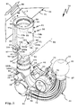
- Figur 1
- eine perspektivische Schrägansicht von in Fahrtrichtung gesehen schräg hinten oben einer Anhängekupplung, deren Kupplungsarm teilweise in eine Fahrzeughalterung eingesteckt ist,
- Figur 2
- den Kupplungsarm der Anhängekupplung gemäß
Figur 1 von schräg vorn (in Fahrtrichtung nach hinten gesehen), - Figur 3
- eine Explosionsdarstellung des Kupplungsarms gemäß
Figur 2 von schräg hinten oben sowie einer Fahrzeug-Kontakteinheit, und - Figur 4
- die Anhängekupplung gemäß der vorstehenden Figuren in der Perspektive gemäß
Figur 3 , wobei der Kupplungsarm vollständig in die Fahrzeughalterung eingesteckt ist und die Gebrauchsstellung einnimmt.
- FIG. 1
- a perspective oblique view of seen in the direction of travel obliquely behind the top of a trailer hitch whose coupling arm is partially inserted into a vehicle mount,
- FIG. 2
- the coupling arm of the trailer coupling according to
FIG. 1 from diagonally forward (seen in the direction of travel to the rear), - FIG. 3
- an exploded view of the coupling arm according to
FIG. 2 from obliquely behind the top and a vehicle contact unit, and - FIG. 4
- the hitch according to the preceding figures in perspective
FIG. 3 , with the coupling arm completely in the Vehicle holder is inserted and occupies the position of use.
Eine in der Zeichnung dargestellte Anhängekupplung 10 umfasst einen Kupplungsarm 20, der an einer Fahrzeughalterung 50 lösbar befestigbar ist. Der Kupplungsarm 20 weist einen Steckvorsprung 21 auf, der in eine Steckaufnahme 52 der Fahrzeughalterung 50 einsteckbar ist. Die Fahrzeughalterung 50 umfasst ein Gehäuse, z.B. eine Hülse 51, das bzw. welche die Steckaufnahme 52 begrenzt. Der Kupplungsarm 20 ist entlang einer Steckachse S in die Steckaufnahme 52 einsteckbar bzw. aus dieser wieder entnehmbar.A
Man kann sich vorstellen, das alternativ auch eine Schwenk-Schiebelagerung anhand eines schematisch dargestellten Lagers 121 möglich wäre, d.h. dass beispielsweise der Kupplungsarm 20 um die Schwenkachse S schwenkbar und entlang dieser auch verschieblich bezüglich der Fahrzeughalterung 50 ist. Der Kupplungsarm 20 ist also beispielsweise zwischen einer in
Die Fahrzeughalterung 50 ist beispielsweise an einem Querträger 91 befestigt, der sich hinten am Kraftfahrzeug 90, unterhalb eines Stoßfänger 92 des Kraftfahrzeugs 90, erstreckt. Der Querträger 91 sowie beispielsweise diesen an die Karosserie des Kraftfahrzeugs 90 anbindende (nicht dargestellte) Seitenträger sind Bestandteile einer vorzugsweise zur Anhängekupplung 10 gehörenden Trägerkonstruktion.The
Am freien, vom Kraftfahrzeug 90 abgewandten Endbereich des Kupplungsarms 20 ist ein Kuppelkörper 22, zum Beispiel eine Kupplungskugel 23, angeordnet. Ein Armabschnitt 24 des Kupplungsarms 20 zwischen dem Steckende des Kupplungsarms 20, dem Steckvorsprung 21, und dem Kuppelkörper 22 ist beispielsweise in an sich bekannter Weise gekrümmt. An einem unteren Bereich 26 des Armabschnitts 24, der sich zwischen einem hoch stehenden Abschnitt 27, an dessen freiem Endbereich der Kuppelkörper 22 angeordnet ist, ist eine Kontakteinheit-Halterung 25 vorgesehen, die zum Halten einer Fahrzeug-Kontakteinheit 70 dient.At the free, remote from the
Die Fahrzeug-Kontakteinheit 70 ist beispielsweise entsprechend DIN 1724 mit 7 elektrischen Anschlusskontakten 71 oder nach ISO 11446 mit 13 elektrischen Anschlusskontakten 71 versehen, die schematisch angedeutet sind. Die ganz konkrete Ausgestaltung der Fahrzeug-Kontakteinheit 70 ist jedoch nicht auf diese beiden Normen eingeschränkt, d.h. es können auch andere Gestaltungen, auch proprietäre Ausgestaltungen, der Kontakteinheit 70 vorgesehen sein.The
In die Fahrzeug-Kontakteinheit 70 ist eine Anhänger-Kontakteinheit 95 einsteckbar, die beispielsweise mehrere Kontaktstifte 96 oder andere Steckkontakte zum Einstecken in Steckaufnahmen der Fahrzeug-Kontakteinheit 70 aufweist, an denen die elektrischen Anschlusskontakte 71 vorgesehen sind.In the vehicle-
Zwischen dem Steckvorsprung 21 und dem unteren Bereich 26 des Kupplungsarms 20 erstreckt sich noch ein Bogenabschnitt 28, von dem der Steckvorsprung 21 und der unteren Bereich 26 des Armabschnitts 24 etwa rechtwinkelig absteht. Auf die ganz konkrete Ausführungsform oder Winkelgestalt kommt es jedoch nicht an.Between the plug-in
Der Kupplungsarm 20 ist an der Fahrzeughalterung 50 anhand einer Fixiereinrichtung 40 fixierbar und verriegelbar. Die Fixiereinrichtung 40 umfasst beispielsweise Formschlussvorsprünge 30, die in korrespondierende Formschlussaufnahmen 54 am unteren Rand 53 der Fahrzeughalterung 50 eingreifen, wenn der Kupplungsarm 20 in die Fahrzeughalterung 50 vollständig eingesteckt ist.The
Mithin stellen die Formschlussvorsprünge 30 und die Formschlussaufnahmen 54 Formschlusskonturen 38, 58 dar.Consequently, the form-fitting
Die Formschlussaufnahmen 54 weisen beispielsweise schräg zueinander verlaufende Formschlussflächen 57 auf, die mit ebenfalls schräg verlaufenden Formschlussflächen 31 der Formschlussvorsprünge 30 in formschlüssigen Kontakt stehen, wenn die Formschlussvorsprünge 30 in die Formschlussaufnahmen 54 eingreifen.The form-fitting
Die Formschlussvorsprünge 30 und die Formschlussaufnahmen 54 sind beispielsweise in einem Winkelabstand von 180° zueinander angeordnet.The form-fitting
Die Formschlussaufnahmen 54 sind in der Seitenansicht V-förmig, ebenso die dazu passenden Formschlussvorsprünge 30. Man kann die Formschlussflächen 31, 57 auch als Schrägflächen oder Keilflächen bezeichnen, die für einen festen Sitz des Kupplungsarms 20 an der Fahrzeughalterung 50 in der Gebrauchsstellung G sorgen.The form-fitting
Diese Keilflächen oder Schrägflächen werden durch eine axiale Kraft ineinander gezogen, die entlang der Steckachse S verläuft. Hierzu hat die Verriegelungseinrichtung Sperrelemente 41, z.B. Kugeln, die durch einen Betätigungskörper 42 nach radial außen aus dem Steckvorsprung 21 des Kupplungsarms 20 heraus betätigbar sind, so dass sie in eine Aufnahme 55, beispielsweise in der Art einer Kugelsitzrinne oder dergleichen, hineingedrückt werden. Durch entsprechende Schrägverläufe der Aufnahme 55 und der Sperrelemente 41 wird eine Kraft im Sinne eines Hineinziehens des Steckvorsprungs 21 in die Steckaufnahme 52 erzeugt, wodurch die Formschlussvorsprünge 30 keilartig in die Formschlussaufnahmen 54 eindringen. Dadurch ist eine Verdrehung des Kupplungsarms 20 um die Steckachse S verhindert. Das ist an sich bei Steck-Kupplungen dieser Art bekannt und lässt sich ohne weiteres auch im Zusammenhang mit dem Lager 121 realisieren, das heißt dass der Kupplungsarm 20 auch bei der Lagerung anhand des Lagers 121 durch die Fixiereinrichtung 40, jedenfalls die Formschlusskonturen 38, 58 an der Fahrzeughalterung 50 in der Gebrauchsstellung G sicher fixierbar ist.These wedge surfaces or inclined surfaces are pulled into each other by an axial force which extends along the through-axle S. For this purpose, the locking device has locking
Der Betätigungskörper 42, beispielsweise ein sogenannter Sperrbolzen, ist durch eine nicht dargestellte Feder in Richtung der Sperrstellung, in welcher die Sperrelemente 41 in die Aufnahme 55 gedrückt werden, belastet und kann anhand eines Handrads 43 oder eines sonstigen Betätigungsmechanismus', manuell oder motorisch in eine Lösestellung verstellt werden, in welcher die Sperrelemente 41 aus der Aufnahme 55 heraus und in den Steckvorsprung 21 bzw. dort angeordnete Kanäle hinein gelangen können.The actuating
Die vorgenannte Verriegelung und Fixierung ist also auch bei einem an der Fahrzeughalterung verschieblich und/oder schwenkbar gelagerten Kupplungsarm möglich.The aforementioned locking and fixing is thus also possible with a sliding on the vehicle mount and / or pivotally mounted coupling arm.
Die Hülse 51 der Fahrzeughalterung 50 ist oben offen (Öffnung 56), könnte aber auch ohne weiteres geschlossen sein. Die nachfolgend erläuterte elektrische Verbindung zwischen einerseits der Fahrzeughalterung 50 und andererseits dem Kupplungsarm 20 und die weitere Verbindung mit einem Bordnetz 93 des Kraftfahrzeugs 90 sind dennoch möglich.The
Die elektrischen Komponenten sind nämlich im Wesentlichen außenseitig am Kupplungsarm 20 und, soweit möglich, auch außenseitig an der Fahrzeughalterung 50 vorgesehen, was sogar eine nachträgliche Montage der Elektrik der Anhängekupplung 10 ohne weiteres möglich macht.The electrical components are namely provided on the outside of the
Die Fahrzeug-Kontakteinheit 70 weist beispielsweise ein Gehäuse 72 auf, das durch einen Deckel 73 verschließbar ist. Der Deckel 73 ist beispielsweise anhand eines Schwenklagers 79 schwenkbar am Gehäuse 72 gelagert. Hinter dem Deckel 73, der eine Steckaufnahme 74 der Fahrzeug-Kontakteinheit 70 verdeckt (was in der Zeichnung dargestellt ist), sind die Anschlusskontakte 71, beispielsweise 7 oder 13 Anschlusskontakte 71, angeordnet. Die Anschlusskontakte 71 werden von einem Steuergerät 75 angesteuert, das in der Fahrzeug-Kontakteinheit 70 integriert ist. Das Steuergerät 75 weist beispielsweise einen Buskontroller 76 auf, der über elektrische Busleitungen 77 ansteuerbar ist bzw. über elektrische Busleitungen 77 kommuniziert. Der Buskontroller 76 bildet eine Busschnittstelle und zugleich auch eine serielle Schnittstelle der Fahrzeug-Kontakteinheit 70.The
Beispielsweise handelt es sich bei dem Bus, den der Buskontroller 76 bedient, um einen CAN-Bus oder dergleichen.For example, the bus that the bus controller 76 uses is a CAN bus or the like.
Die Busleitungen 77a, 77b sind also beispielsweise CAN-Low (L) und CAN-High (H) Leitungen (CAN = Controller-Area-Network).The
Es muss sich aber bei dem durch den Buskontroller 76 bedienten Bus nicht zwingend um einen Bus handeln, der bei Kraftfahrzeugen üblich ist, z.B. um einen CAN oder Flexray-Bus. Es kann auch ein proprietärer Bus vorgesehen sein, beispielsweise zur Kommunikation mit dem später noch beschriebenen Steuergerät 98, das an Bord des Kraftfahrzeugs 90 angeordnet ist.However, the bus served by the bus controller 76 need not necessarily be a bus common to motor vehicles, e.g. to a CAN or Flexray bus. A proprietary bus may also be provided, for example for communication with the later-described
Weiterhin ist das Steuergerät 75 an zwei elektrische Versorgungsleitungen 78 angeschlossen, die die Fahrzeug-Kontakteinheit 70 mit elektrischer Energie versorgen. Eine Versorgungsleitung 78a weist beispielsweise ein Massepotenzial MP auf, die andere Versorgungsleitung 78b ein Versorgungspotenzial P, z.B. 12 Volt.Furthermore, the
Die Leitungen 77, 78 bilden Adern oder Einzelleitungen einer Anschlussleitung 80, die einen mit dem Bordnetz 93 verbundenen Bordnetz-Abschnitt 81 und einen mit der Fahrzeug-Kontakteinheit 70 verbundenen Kontakteinheit-Abschnitt 82 umfasst.The
Die Abschnitte 81, 82 weisen jeweils die erwähnten Einzelleitungen oder Adern auf, nämlich die Leitungen 77a, 77b, 78a, 78b,die jedoch nur im Bereich des Bordnetz-Abschnittes 81 einzeln gezeichnet sind.The
Der Bordnetz-Abschnitt 82 umfasst Stränge oder Teil-Leitungen 83, 84, die die Leitungen 77a, 77b bzw. 78a, 78b umfassen. Die Leitungen 83, 84 sind in Leitungskanälen 59 der Fahrzeughalterung 50 zu dem Bordnetz 93 oder dem Steuergerät 98, das sozusagen direkt in die Fahrzeugelektrik des Kraftfahrzeugs 90 eingebunden ist, geführt. Die Leitungen 83, 84 könnten auch frei geführte Leitungen sein oder in nutförmigen Vertiefungen, beispielsweise am Außenumfang, der Fahrzeughalterung 50 aufgenommen sein.The vehicle
Es sind beide Varianten möglich, nämlich dass die Leitungen 83, 84 zunächst zum Steuergerät 98 führen, das dann eine weitere Signalverarbeitung durchführt und mit dem Bordnetz 93 verbunden ist. Aber auch eine direkte Verbindung der Busleitungen 77 und der Versorgungsleitungen 78 mit dem Bordnetz 93 ist möglich. Wenn die Funktionen, beispielsweise Überwachung, Steuerung und dergleichen, des Steuergeräts 98 nicht notwendig sind, ist die letztgenannte Variante ohne weiteres realisierbar.Both variants are possible, namely that the
Die beiden Abschnitte 81, 82 sind durch Kontaktelemente 100, 101 und 150, 151 elektrisch miteinander lösbar verbindbar. Die Kontaktelemente 100, 101 sind dabei mit dem Kontakteinheit-Abschnitt 82 verbunden und befinden sich an den Formschlusskonturen 38 des Kupplungsarms 20. Den Kontaktelementen 100, 101 sind die anderen Kontaktelemente 150, 151 zugeordnet, die ihrerseits wiederum an der Fahrzeughalterung 50, nämlich im Bereich der Formschlusskonturen 58 angeordnet sind.The two
Das Kontaktelement 100 weist zwei Kontakte 102, nämlich einen mit der Busleitung 77a verbundenen Kontakt 102a und einen mit der Busleitung 77b verbundenen Kontakt 102b, auf. Das Kontaktelement 101 hat Kontakte 103a und 103b, die mit den Versorgungsleitungen 78a und 78b verbunden sind.The
Die Kontaktelemente 150, 151 haben ebenfalls jeweils 2 Kontakte, nämlich Kontakte 152a, 152b für die Busleitungen 77a und 77b sowie Kontakte 153a, 153b für die Versorgungsleitungen 78a und 78b.The
Die Kontaktelemente 100, 101 weisen beispielsweise ein Gehäuse oder einen Haltekörper 104 auf, an dem die jeweiligen Kontakte 102 und 103 angeordnet sind. Die Haltekörper 104 sind beispielsweise aus Kunststoff oder einem sonstigen elektrisch isolierenden Material.The
Die Kontakte 102, 103 sind vorzugsweise angefedert. Beispielsweise sind die Kontakte 102, 103 durch federnde Stifte oder Pins gebildet. Die Federn sind zweckmäßigerweise im Innern der Haltekörpern 104 angeordnet. Es ist auch möglich, dass die Kontakte 102, 103 z.B. als federnde Kontaktfahnen ausgestaltet sind.The contacts 102, 103 are preferably spring-loaded. For example, the contacts 102, 103 are formed by resilient pins or pins. The springs are expediently arranged in the interior of the holding
Die Kontakte 102, 103 bestehen beispielsweise aus Metall, insbesondere aus einem Edelmetall, das geringere Oxidationstendenzen hat.The contacts 102, 103 consist for example of metal, in particular of a noble metal, which has lower oxidation tendencies.
Die Kontaktelemente 150, 151 können beispielsweise an Haltekörpern 154 vorgesehen sein, für die Aufnahmen 60, zum Beispiel Steckaufnahmen oder dergleichen, an der Fahrzeughalterung 50 vorgesehen sind. Die Kontakte 152a, 152b sowie Kontakte 153a, 153b können beispielsweise Metallflächen sein, die direkt und ungefedert an den Haltekörpern 154 vorgesehen sind. Es ist aber auch denkbar, dass beispielsweise die Fahrzeughalterung 50 im Bereich der Kontakte 152a, 152b sowie Kontakte 153a, 153b elektrisch isolierend ist, jedenfalls dass die Kontakte direkt an der Fahrzeughalterung 50 vorgesehen sind.The
Es ist auch möglich, dass die Kontakte 152a, 152b und/oder die Kontakte 153a, 153b oder auch die Kontakte 102, 103 mit einer elektrischen Isolation versehen sind, so dass sie bei Kontakt mit dem Material oder Grundkörper der Fahrzeughalterung 50 oder des Kupplungsarms 20 keine elektrische Leitung herstellen, diesem Grundkörper gegenüber also isoliert sind. Beispielsweise sind rückseitig, d.h. im Kontaktbereich mit der Hülse 51, an den Kontakten 152a, 152b und/oder den Kontakten 153a, 153b Isolationen möglich. Selbstverständlich könnten die Kontakte 102, 103 auch integral am Kupplungsarm 20 bzw. dessen Grundkörper vorgesehen sein, die dann ihrerseits eine gewisse Isolation dem Grundkörper gegenüber aufweisen.It is also possible for the
Von der Fahrzeug-Kontakteinheit 70 führt ein Strang 85 zu dem Kontaktelement 100, wo dann die beiden Busleitungen 77 sozusagen ausgeschleift werden. Der Strang 85 enthält die Busleitungen 77 und die Versorgungsleitungen 78. Im Bereich der Fahrzeug-Kontakteinheit 70 ist vorzugsweise eine Tülle 87 vorgesehen, das heißt dass die Anschlussleitung 80 seitlich und durch eine Tülle 87 geschützt aus dem Gehäuse 72 heraus geführt ist. Die Leitungen 77, 78 sind zweckmäßigerweise ummantelt, d.h. beispielsweise durch ein flexibles Schlauchmantelmaterial geschützt.From the
Im Bereich des Kontaktelements 100 verzweigt die Anschlussleitung 80 an einer Verzweigung 88, wobei in dem dadurch gebildeten Strang 86 die beiden Versorgungsleitungen 78 weiter zu dem Kontaktelement 100 geführt sind.In the region of the
Die Stränge 85, 86 sind vorzugsweise spritzwassergeschützt. Es ist vorteilhaft, wenn die Anschlussleitung 80 integral in das jeweilige Kontaktelement 100, 101 hinein geführt ist, beispielsweise dort anhand einer Verschweißung, einer Tülle oder dergleichen, vor Wasser und anderen Umwelteinflüssen geschützt ist.The
Die Kontaktelemente 100, 101 sind beispielsweise in Steckhalterungen 34 der Formschlussvorsprünge 30 aufgenommen. Die Steckhalterungen 34 sind beispielsweise die Endbereiche von Kanälen 35, die sich z.B. parallel zur Steckachse S, in den Formschlussvorsprüngen 30 erstrecken. Durch die Kanäle 35 hindurch können die Stränge 85, 86, jedenfalls die darin enthaltenen elektrischen Leitungen, des Kontakteinheit-Abschnitts 82 hindurch geführt werden. Die Kontaktelemente 101, 100 können in den Steckhalterungen 34 beispielsweise zusätzlich angeklebt werden, verrastet oder dergleichen anderweitig stoffschlüssig und/oder formschlüssig gesichert sein. Eine Steckmontage der Kontaktelemente 100, 101 in den Steckhalterungen 34 ist beispielsweise durch Pfeile M in
Auch die Fahrzeug-Kontakteinheit 70 ist ohne weiteres an dem Grundkörper des Kupplungsarms 20, auch nachträglich, montierbar. Beispielsweise umfasst die Kontakteinheit-Halterung 25 zwei Aufnahmeösen oder Schraubösen 29, die von (nicht dargestellten) Schrauben durchdrungen werden können, die ferner Schraubösen 69 der Fahrzeug-Kontakteinheit 70 durchdringen.Also, the
Die Kontaktelemente 100, 101 sind an Scheitelbereichen 33 der Formschlussvorsprünge 30 angeordnet. Eine Scheitelfläche 32 zwischen den schräg verlaufenden Formschlussflächen 31 ist nicht in direktem Kontakt mit einem Boden 61 der Formschlussaufnahmen 54, wo die gegenüberliegenden Kontaktelemente 150, 151 angeordnet sind. Der Boden 61 und die Scheitelfläche 32 sind also nicht durch den Formschlusskontakt der Formschlusskonturen 58, 38 direkt belastet.The
Claims (14)
Applications Claiming Priority (1)
| Application Number | Priority Date | Filing Date | Title |
|---|---|---|---|
| DE102014003185.3A DE102014003185A1 (en) | 2014-03-01 | 2014-03-01 | Trailer coupling with a vehicle contact unit |
Publications (2)
| Publication Number | Publication Date |
|---|---|
| EP2913208A1 true EP2913208A1 (en) | 2015-09-02 |
| EP2913208B1 EP2913208B1 (en) | 2019-03-20 |
Family
ID=52577750
Family Applications (1)
| Application Number | Title | Priority Date | Filing Date |
|---|---|---|---|
| EP15156708.8A Active EP2913208B1 (en) | 2014-03-01 | 2015-02-26 | Tow bar with a vehicle contact unit |
Country Status (2)
| Country | Link |
|---|---|
| EP (1) | EP2913208B1 (en) |
| DE (1) | DE102014003185A1 (en) |
Cited By (3)
| Publication number | Priority date | Publication date | Assignee | Title |
|---|---|---|---|---|
| WO2018045037A1 (en) * | 2016-08-30 | 2018-03-08 | Horizon Global Americas Inc. | Detachable receiver |
| US20200180373A1 (en) * | 2018-12-06 | 2020-06-11 | Midway Products Group, Inc. | Hitch assembly |
| EP4134253A1 (en) * | 2021-08-13 | 2023-02-15 | ACPS Automotive GmbH | Trailer coupling |
Citations (8)
| Publication number | Priority date | Publication date | Assignee | Title |
|---|---|---|---|---|
| EP0747244A1 (en) * | 1995-06-07 | 1996-12-11 | Netherlands Car B.V. | A coupling device suitable for coupling a vehicle and a trailer to be moved by said vehicle, as well as a vehicle part and a trailer part suitable for such a coupling device |
| EP0950549A1 (en) * | 1998-04-17 | 1999-10-20 | Ellebi S.r.l. | Vehicle towing member with a removable but automatically lockable ball hook, provided with a current socket |
| GB2363262A (en) * | 2000-06-09 | 2001-12-12 | Seat Sa | Removable tow-hitch and electrical connector |
| DE10027571A1 (en) | 2000-06-02 | 2001-12-13 | Oris Fahrzeugteile Riehle H | Interchangeable towing hook for vehicles, includes connectors for trailer supply voltage and functional signals taken to trailer decoder and power switching |
| EP1757488A2 (en) * | 2005-08-25 | 2007-02-28 | WESTFALIA - Automotive GmbH | Support structure for vehicle and corresponding holder assembly |
| WO2007091222A1 (en) * | 2006-02-10 | 2007-08-16 | Jakobus Nikolaas Steenkamp | Tow hitch |
| EP2199118A1 (en) | 2008-11-20 | 2010-06-23 | Ing. Plini e Gigliotti S.R.L. | Tow bar |
| EP2428404A1 (en) * | 2010-09-13 | 2012-03-14 | WESTFALIA - Automotive GmbH | Load carrying sytsem |
Family Cites Families (1)
| Publication number | Priority date | Publication date | Assignee | Title |
|---|---|---|---|---|
| DE102007060529A1 (en) * | 2007-12-13 | 2009-06-18 | Westfalia-Automotive Gmbh | Trailer coupling with insertion aid device |
-
2014
- 2014-03-01 DE DE102014003185.3A patent/DE102014003185A1/en not_active Withdrawn
-
2015
- 2015-02-26 EP EP15156708.8A patent/EP2913208B1/en active Active
Patent Citations (8)
| Publication number | Priority date | Publication date | Assignee | Title |
|---|---|---|---|---|
| EP0747244A1 (en) * | 1995-06-07 | 1996-12-11 | Netherlands Car B.V. | A coupling device suitable for coupling a vehicle and a trailer to be moved by said vehicle, as well as a vehicle part and a trailer part suitable for such a coupling device |
| EP0950549A1 (en) * | 1998-04-17 | 1999-10-20 | Ellebi S.r.l. | Vehicle towing member with a removable but automatically lockable ball hook, provided with a current socket |
| DE10027571A1 (en) | 2000-06-02 | 2001-12-13 | Oris Fahrzeugteile Riehle H | Interchangeable towing hook for vehicles, includes connectors for trailer supply voltage and functional signals taken to trailer decoder and power switching |
| GB2363262A (en) * | 2000-06-09 | 2001-12-12 | Seat Sa | Removable tow-hitch and electrical connector |
| EP1757488A2 (en) * | 2005-08-25 | 2007-02-28 | WESTFALIA - Automotive GmbH | Support structure for vehicle and corresponding holder assembly |
| WO2007091222A1 (en) * | 2006-02-10 | 2007-08-16 | Jakobus Nikolaas Steenkamp | Tow hitch |
| EP2199118A1 (en) | 2008-11-20 | 2010-06-23 | Ing. Plini e Gigliotti S.R.L. | Tow bar |
| EP2428404A1 (en) * | 2010-09-13 | 2012-03-14 | WESTFALIA - Automotive GmbH | Load carrying sytsem |
Cited By (8)
| Publication number | Priority date | Publication date | Assignee | Title |
|---|---|---|---|---|
| WO2018045037A1 (en) * | 2016-08-30 | 2018-03-08 | Horizon Global Americas Inc. | Detachable receiver |
| CN109890631A (en) * | 2016-08-30 | 2019-06-14 | 地平线全球美洲股份有限公司 | Removeably received device |
| US10836225B2 (en) | 2016-08-30 | 2020-11-17 | Horizon Global Americas Inc. | Detachable receiver |
| US11752817B2 (en) | 2016-08-30 | 2023-09-12 | Horizon Global Americas Inc. | Detachable receiver |
| CN109890631B (en) * | 2016-08-30 | 2023-10-31 | 地平线全球美洲股份有限公司 | detachable receiver |
| US20200180373A1 (en) * | 2018-12-06 | 2020-06-11 | Midway Products Group, Inc. | Hitch assembly |
| US11679636B2 (en) * | 2018-12-06 | 2023-06-20 | Midway Products Group, Inc. | Hitch assembly |
| EP4134253A1 (en) * | 2021-08-13 | 2023-02-15 | ACPS Automotive GmbH | Trailer coupling |
Also Published As
| Publication number | Publication date |
|---|---|
| EP2913208B1 (en) | 2019-03-20 |
| DE102014003185A1 (en) | 2015-09-03 |
Similar Documents
| Publication | Publication Date | Title |
|---|---|---|
| DE19815843B4 (en) | Device for energy and signal transmission between parts of a vehicle | |
| EP1824691B1 (en) | System for connecting supply lines | |
| DE102014108071A1 (en) | Towing | |
| EP3113294B1 (en) | Electrical connection system for the electrical connection of a trailer to a towing vehicle | |
| DE202016105321U1 (en) | Rangierantriebssystem and vehicle with such | |
| EP2070311A1 (en) | Modular camera system | |
| EP2913208B1 (en) | Tow bar with a vehicle contact unit | |
| EP3034335B1 (en) | Trailer coupling | |
| DE10021232B4 (en) | trailer hitch | |
| DE102012004345A1 (en) | Clutch control device and trailer coupling equipped therewith | |
| DE102017201245A1 (en) | Electrical system for a vehicle | |
| DE102018132867A1 (en) | Connector device for a vehicle for transmitting data between coupled vehicles and system and vehicle with it | |
| DE10027571A1 (en) | Interchangeable towing hook for vehicles, includes connectors for trailer supply voltage and functional signals taken to trailer decoder and power switching | |
| DE102019207384B4 (en) | Inductive electrical energy transfer between a towing vehicle and a towed vehicle | |
| DE4235539B4 (en) | Towing, in particular semitrailer | |
| EP3466728B1 (en) | Trailer device for a motor vehicle | |
| DE102010051584A1 (en) | Circuit device used in towing vehicle e.g. towed passenger car, has two bus modules connected to contacts of plug connection through two different bus lines, respectively | |
| DE202021106965U1 (en) | Connector for a combined electrical connection and data connection | |
| DE102017221574A1 (en) | Battery connector actuation system | |
| DE102015122424A1 (en) | Method for detecting a surrounding area of a trailer with a motor vehicle and a trailer, and camera system | |
| DE102016015048A1 (en) | Holding arrangement for releasably mounting an electrical device in the interior of a motor vehicle | |
| DE102008044941A1 (en) | Power supply device for an overrun trailer vehicle | |
| DE102009050932A1 (en) | Trailer coupling device for motor vehicle, has ball neck, by which ball head is supported, where receiver opening is provided in area of ball head | |
| DE10308078A1 (en) | Device for transmitting signals/energy has transmission module on vehicle body side integrated into seat rail system, module on seat side coupled into rail system, uses displacement current in rails | |
| EP0762561B1 (en) | Electric conductor especially for use in vehicles |
Legal Events
| Date | Code | Title | Description |
|---|---|---|---|
| PUAI | Public reference made under article 153(3) epc to a published international application that has entered the european phase |
Free format text: ORIGINAL CODE: 0009012 |
|
| AK | Designated contracting states |
Kind code of ref document: A1 Designated state(s): AL AT BE BG CH CY CZ DE DK EE ES FI FR GB GR HR HU IE IS IT LI LT LU LV MC MK MT NL NO PL PT RO RS SE SI SK SM TR |
|
| AX | Request for extension of the european patent |
Extension state: BA ME |
|
| 17P | Request for examination filed |
Effective date: 20160226 |
|
| RBV | Designated contracting states (corrected) |
Designated state(s): AL AT BE BG CH CY CZ DE DK EE ES FI FR GB GR HR HU IE IS IT LI LT LU LV MC MK MT NL NO PL PT RO RS SE SI SK SM TR |
|
| GRAP | Despatch of communication of intention to grant a patent |
Free format text: ORIGINAL CODE: EPIDOSNIGR1 |
|
| STAA | Information on the status of an ep patent application or granted ep patent |
Free format text: STATUS: GRANT OF PATENT IS INTENDED |
|
| INTG | Intention to grant announced |
Effective date: 20181012 |
|
| GRAS | Grant fee paid |
Free format text: ORIGINAL CODE: EPIDOSNIGR3 |
|
| GRAA | (expected) grant |
Free format text: ORIGINAL CODE: 0009210 |
|
| STAA | Information on the status of an ep patent application or granted ep patent |
Free format text: STATUS: THE PATENT HAS BEEN GRANTED |
|
| AK | Designated contracting states |
Kind code of ref document: B1 Designated state(s): AL AT BE BG CH CY CZ DE DK EE ES FI FR GB GR HR HU IE IS IT LI LT LU LV MC MK MT NL NO PL PT RO RS SE SI SK SM TR |
|
| REG | Reference to a national code |
Ref country code: GB Ref legal event code: FG4D Free format text: NOT ENGLISH |
|
| REG | Reference to a national code |
Ref country code: CH Ref legal event code: EP |
|
| REG | Reference to a national code |
Ref country code: DE Ref legal event code: R096 Ref document number: 502015008381 Country of ref document: DE |
|
| REG | Reference to a national code |
Ref country code: AT Ref legal event code: REF Ref document number: 1110162 Country of ref document: AT Kind code of ref document: T Effective date: 20190415 |
|
| REG | Reference to a national code |
Ref country code: IE Ref legal event code: FG4D Free format text: LANGUAGE OF EP DOCUMENT: GERMAN |
|
| REG | Reference to a national code |
Ref country code: NL Ref legal event code: MP Effective date: 20190320 |
|
| PG25 | Lapsed in a contracting state [announced via postgrant information from national office to epo] |
Ref country code: FI Free format text: LAPSE BECAUSE OF FAILURE TO SUBMIT A TRANSLATION OF THE DESCRIPTION OR TO PAY THE FEE WITHIN THE PRESCRIBED TIME-LIMIT Effective date: 20190320 Ref country code: NO Free format text: LAPSE BECAUSE OF FAILURE TO SUBMIT A TRANSLATION OF THE DESCRIPTION OR TO PAY THE FEE WITHIN THE PRESCRIBED TIME-LIMIT Effective date: 20190620 Ref country code: SE Free format text: LAPSE BECAUSE OF FAILURE TO SUBMIT A TRANSLATION OF THE DESCRIPTION OR TO PAY THE FEE WITHIN THE PRESCRIBED TIME-LIMIT Effective date: 20190320 Ref country code: LT Free format text: LAPSE BECAUSE OF FAILURE TO SUBMIT A TRANSLATION OF THE DESCRIPTION OR TO PAY THE FEE WITHIN THE PRESCRIBED TIME-LIMIT Effective date: 20190320 |
|
| REG | Reference to a national code |
Ref country code: LT Ref legal event code: MG4D |
|
| PG25 | Lapsed in a contracting state [announced via postgrant information from national office to epo] |
Ref country code: RS Free format text: LAPSE BECAUSE OF FAILURE TO SUBMIT A TRANSLATION OF THE DESCRIPTION OR TO PAY THE FEE WITHIN THE PRESCRIBED TIME-LIMIT Effective date: 20190320 Ref country code: GR Free format text: LAPSE BECAUSE OF FAILURE TO SUBMIT A TRANSLATION OF THE DESCRIPTION OR TO PAY THE FEE WITHIN THE PRESCRIBED TIME-LIMIT Effective date: 20190621 Ref country code: HR Free format text: LAPSE BECAUSE OF FAILURE TO SUBMIT A TRANSLATION OF THE DESCRIPTION OR TO PAY THE FEE WITHIN THE PRESCRIBED TIME-LIMIT Effective date: 20190320 Ref country code: NL Free format text: LAPSE BECAUSE OF FAILURE TO SUBMIT A TRANSLATION OF THE DESCRIPTION OR TO PAY THE FEE WITHIN THE PRESCRIBED TIME-LIMIT Effective date: 20190320 Ref country code: LV Free format text: LAPSE BECAUSE OF FAILURE TO SUBMIT A TRANSLATION OF THE DESCRIPTION OR TO PAY THE FEE WITHIN THE PRESCRIBED TIME-LIMIT Effective date: 20190320 Ref country code: BG Free format text: LAPSE BECAUSE OF FAILURE TO SUBMIT A TRANSLATION OF THE DESCRIPTION OR TO PAY THE FEE WITHIN THE PRESCRIBED TIME-LIMIT Effective date: 20190620 |
|
| PG25 | Lapsed in a contracting state [announced via postgrant information from national office to epo] |
Ref country code: SK Free format text: LAPSE BECAUSE OF FAILURE TO SUBMIT A TRANSLATION OF THE DESCRIPTION OR TO PAY THE FEE WITHIN THE PRESCRIBED TIME-LIMIT Effective date: 20190320 Ref country code: RO Free format text: LAPSE BECAUSE OF FAILURE TO SUBMIT A TRANSLATION OF THE DESCRIPTION OR TO PAY THE FEE WITHIN THE PRESCRIBED TIME-LIMIT Effective date: 20190320 Ref country code: EE Free format text: LAPSE BECAUSE OF FAILURE TO SUBMIT A TRANSLATION OF THE DESCRIPTION OR TO PAY THE FEE WITHIN THE PRESCRIBED TIME-LIMIT Effective date: 20190320 Ref country code: IT Free format text: LAPSE BECAUSE OF FAILURE TO SUBMIT A TRANSLATION OF THE DESCRIPTION OR TO PAY THE FEE WITHIN THE PRESCRIBED TIME-LIMIT Effective date: 20190320 Ref country code: PT Free format text: LAPSE BECAUSE OF FAILURE TO SUBMIT A TRANSLATION OF THE DESCRIPTION OR TO PAY THE FEE WITHIN THE PRESCRIBED TIME-LIMIT Effective date: 20190720 Ref country code: ES Free format text: LAPSE BECAUSE OF FAILURE TO SUBMIT A TRANSLATION OF THE DESCRIPTION OR TO PAY THE FEE WITHIN THE PRESCRIBED TIME-LIMIT Effective date: 20190320 Ref country code: AL Free format text: LAPSE BECAUSE OF FAILURE TO SUBMIT A TRANSLATION OF THE DESCRIPTION OR TO PAY THE FEE WITHIN THE PRESCRIBED TIME-LIMIT Effective date: 20190320 Ref country code: CZ Free format text: LAPSE BECAUSE OF FAILURE TO SUBMIT A TRANSLATION OF THE DESCRIPTION OR TO PAY THE FEE WITHIN THE PRESCRIBED TIME-LIMIT Effective date: 20190320 |
|
| PG25 | Lapsed in a contracting state [announced via postgrant information from national office to epo] |
Ref country code: SM Free format text: LAPSE BECAUSE OF FAILURE TO SUBMIT A TRANSLATION OF THE DESCRIPTION OR TO PAY THE FEE WITHIN THE PRESCRIBED TIME-LIMIT Effective date: 20190320 Ref country code: PL Free format text: LAPSE BECAUSE OF FAILURE TO SUBMIT A TRANSLATION OF THE DESCRIPTION OR TO PAY THE FEE WITHIN THE PRESCRIBED TIME-LIMIT Effective date: 20190320 |
|
| PG25 | Lapsed in a contracting state [announced via postgrant information from national office to epo] |
Ref country code: IS Free format text: LAPSE BECAUSE OF FAILURE TO SUBMIT A TRANSLATION OF THE DESCRIPTION OR TO PAY THE FEE WITHIN THE PRESCRIBED TIME-LIMIT Effective date: 20190720 |
|
| REG | Reference to a national code |
Ref country code: DE Ref legal event code: R097 Ref document number: 502015008381 Country of ref document: DE |
|
| PLBE | No opposition filed within time limit |
Free format text: ORIGINAL CODE: 0009261 |
|
| STAA | Information on the status of an ep patent application or granted ep patent |
Free format text: STATUS: NO OPPOSITION FILED WITHIN TIME LIMIT |
|
| PG25 | Lapsed in a contracting state [announced via postgrant information from national office to epo] |
Ref country code: DK Free format text: LAPSE BECAUSE OF FAILURE TO SUBMIT A TRANSLATION OF THE DESCRIPTION OR TO PAY THE FEE WITHIN THE PRESCRIBED TIME-LIMIT Effective date: 20190320 |
|
| 26N | No opposition filed |
Effective date: 20200102 |
|
| PG25 | Lapsed in a contracting state [announced via postgrant information from national office to epo] |
Ref country code: SI Free format text: LAPSE BECAUSE OF FAILURE TO SUBMIT A TRANSLATION OF THE DESCRIPTION OR TO PAY THE FEE WITHIN THE PRESCRIBED TIME-LIMIT Effective date: 20190320 |
|
| PG25 | Lapsed in a contracting state [announced via postgrant information from national office to epo] |
Ref country code: TR Free format text: LAPSE BECAUSE OF FAILURE TO SUBMIT A TRANSLATION OF THE DESCRIPTION OR TO PAY THE FEE WITHIN THE PRESCRIBED TIME-LIMIT Effective date: 20190320 |
|
| REG | Reference to a national code |
Ref country code: CH Ref legal event code: PL |
|
| GBPC | Gb: european patent ceased through non-payment of renewal fee |
Effective date: 20200226 |
|
| REG | Reference to a national code |
Ref country code: BE Ref legal event code: MM Effective date: 20200229 |
|
| PG25 | Lapsed in a contracting state [announced via postgrant information from national office to epo] |
Ref country code: LU Free format text: LAPSE BECAUSE OF NON-PAYMENT OF DUE FEES Effective date: 20200226 Ref country code: MC Free format text: LAPSE BECAUSE OF FAILURE TO SUBMIT A TRANSLATION OF THE DESCRIPTION OR TO PAY THE FEE WITHIN THE PRESCRIBED TIME-LIMIT Effective date: 20190320 |
|
| PG25 | Lapsed in a contracting state [announced via postgrant information from national office to epo] |
Ref country code: CH Free format text: LAPSE BECAUSE OF NON-PAYMENT OF DUE FEES Effective date: 20200229 Ref country code: LI Free format text: LAPSE BECAUSE OF NON-PAYMENT OF DUE FEES Effective date: 20200229 |
|
| PG25 | Lapsed in a contracting state [announced via postgrant information from national office to epo] |
Ref country code: GB Free format text: LAPSE BECAUSE OF NON-PAYMENT OF DUE FEES Effective date: 20200226 Ref country code: IE Free format text: LAPSE BECAUSE OF NON-PAYMENT OF DUE FEES Effective date: 20200226 |
|
| PG25 | Lapsed in a contracting state [announced via postgrant information from national office to epo] |
Ref country code: BE Free format text: LAPSE BECAUSE OF NON-PAYMENT OF DUE FEES Effective date: 20200229 |
|
| REG | Reference to a national code |
Ref country code: AT Ref legal event code: MM01 Ref document number: 1110162 Country of ref document: AT Kind code of ref document: T Effective date: 20200226 |
|
| PG25 | Lapsed in a contracting state [announced via postgrant information from national office to epo] |
Ref country code: AT Free format text: LAPSE BECAUSE OF NON-PAYMENT OF DUE FEES Effective date: 20200226 |
|
| PG25 | Lapsed in a contracting state [announced via postgrant information from national office to epo] |
Ref country code: MT Free format text: LAPSE BECAUSE OF FAILURE TO SUBMIT A TRANSLATION OF THE DESCRIPTION OR TO PAY THE FEE WITHIN THE PRESCRIBED TIME-LIMIT Effective date: 20190320 Ref country code: CY Free format text: LAPSE BECAUSE OF FAILURE TO SUBMIT A TRANSLATION OF THE DESCRIPTION OR TO PAY THE FEE WITHIN THE PRESCRIBED TIME-LIMIT Effective date: 20190320 |
|
| PGFP | Annual fee paid to national office [announced via postgrant information from national office to epo] |
Ref country code: FR Payment date: 20220113 Year of fee payment: 8 |
|
| PG25 | Lapsed in a contracting state [announced via postgrant information from national office to epo] |
Ref country code: MK Free format text: LAPSE BECAUSE OF FAILURE TO SUBMIT A TRANSLATION OF THE DESCRIPTION OR TO PAY THE FEE WITHIN THE PRESCRIBED TIME-LIMIT Effective date: 20190320 |
|
| PGFP | Annual fee paid to national office [announced via postgrant information from national office to epo] |
Ref country code: DE Payment date: 20230204 Year of fee payment: 9 |
|
| PG25 | Lapsed in a contracting state [announced via postgrant information from national office to epo] |
Ref country code: FR Free format text: LAPSE BECAUSE OF NON-PAYMENT OF DUE FEES Effective date: 20230228 |