EP2428404A1 - Load carrying sytsem - Google Patents
Load carrying sytsem Download PDFInfo
- Publication number
- EP2428404A1 EP2428404A1 EP11007289A EP11007289A EP2428404A1 EP 2428404 A1 EP2428404 A1 EP 2428404A1 EP 11007289 A EP11007289 A EP 11007289A EP 11007289 A EP11007289 A EP 11007289A EP 2428404 A1 EP2428404 A1 EP 2428404A1
- Authority
- EP
- European Patent Office
- Prior art keywords
- plug
- receptacle
- vehicle
- projection
- carrier
- Prior art date
- Legal status (The legal status is an assumption and is not a legal conclusion. Google has not performed a legal analysis and makes no representation as to the accuracy of the status listed.)
- Granted
Links
- 230000008878 coupling Effects 0.000 claims description 42
- 238000010168 coupling process Methods 0.000 claims description 42
- 238000005859 coupling reaction Methods 0.000 claims description 42
- 238000003780 insertion Methods 0.000 claims description 18
- 230000037431 insertion Effects 0.000 claims description 18
- 230000000903 blocking effect Effects 0.000 claims description 11
- 230000005291 magnetic effect Effects 0.000 claims description 5
- 238000007789 sealing Methods 0.000 claims description 3
- 239000000969 carrier Substances 0.000 description 11
- 210000002435 tendon Anatomy 0.000 description 8
- 230000033001 locomotion Effects 0.000 description 4
- 210000002023 somite Anatomy 0.000 description 4
- 230000000694 effects Effects 0.000 description 3
- 230000013011 mating Effects 0.000 description 3
- 238000003825 pressing Methods 0.000 description 3
- 239000000758 substrate Substances 0.000 description 3
- 238000010276 construction Methods 0.000 description 2
- 238000000034 method Methods 0.000 description 2
- 230000002093 peripheral effect Effects 0.000 description 2
- 238000000418 atomic force spectrum Methods 0.000 description 1
- 230000002457 bidirectional effect Effects 0.000 description 1
- 230000005540 biological transmission Effects 0.000 description 1
- 239000000470 constituent Substances 0.000 description 1
- 238000009826 distribution Methods 0.000 description 1
- 230000002349 favourable effect Effects 0.000 description 1
- 230000005294 ferromagnetic effect Effects 0.000 description 1
- 238000004519 manufacturing process Methods 0.000 description 1
- 238000004091 panning Methods 0.000 description 1
- 230000001681 protective effect Effects 0.000 description 1
- 238000003860 storage Methods 0.000 description 1
Images


Classifications
-
- B—PERFORMING OPERATIONS; TRANSPORTING
- B60—VEHICLES IN GENERAL
- B60R—VEHICLES, VEHICLE FITTINGS, OR VEHICLE PARTS, NOT OTHERWISE PROVIDED FOR
- B60R9/00—Supplementary fittings on vehicle exterior for carrying loads, e.g. luggage, sports gear or the like
- B60R9/06—Supplementary fittings on vehicle exterior for carrying loads, e.g. luggage, sports gear or the like at vehicle front or rear
-
- B—PERFORMING OPERATIONS; TRANSPORTING
- B60—VEHICLES IN GENERAL
- B60D—VEHICLE CONNECTIONS
- B60D1/00—Traction couplings; Hitches; Draw-gear; Towing devices
- B60D1/01—Traction couplings or hitches characterised by their type
- B60D1/06—Ball-and-socket hitches, e.g. constructional details, auxiliary devices, their arrangement on the vehicle
-
- B—PERFORMING OPERATIONS; TRANSPORTING
- B60—VEHICLES IN GENERAL
- B60D—VEHICLE CONNECTIONS
- B60D1/00—Traction couplings; Hitches; Draw-gear; Towing devices
- B60D1/48—Traction couplings; Hitches; Draw-gear; Towing devices characterised by the mounting
- B60D1/52—Traction couplings; Hitches; Draw-gear; Towing devices characterised by the mounting removably mounted
-
- B—PERFORMING OPERATIONS; TRANSPORTING
- B60—VEHICLES IN GENERAL
- B60D—VEHICLE CONNECTIONS
- B60D1/00—Traction couplings; Hitches; Draw-gear; Towing devices
- B60D1/58—Auxiliary devices
- B60D1/60—Covers, caps or guards, e.g. comprising anti-theft devices
-
- B—PERFORMING OPERATIONS; TRANSPORTING
- B60—VEHICLES IN GENERAL
- B60D—VEHICLE CONNECTIONS
- B60D1/00—Traction couplings; Hitches; Draw-gear; Towing devices
- B60D1/58—Auxiliary devices
- B60D1/62—Auxiliary devices involving supply lines, electric circuits, or the like
- B60D1/64—Couplings or joints therefor
-
- B—PERFORMING OPERATIONS; TRANSPORTING
- B60—VEHICLES IN GENERAL
- B60R—VEHICLES, VEHICLE FITTINGS, OR VEHICLE PARTS, NOT OTHERWISE PROVIDED FOR
- B60R19/00—Wheel guards; Radiator guards, e.g. grilles; Obstruction removers; Fittings damping bouncing force in collisions
- B60R19/02—Bumpers, i.e. impact receiving or absorbing members for protecting vehicles or fending off blows from other vehicles or objects
- B60R19/48—Bumpers, i.e. impact receiving or absorbing members for protecting vehicles or fending off blows from other vehicles or objects combined with, or convertible into, other devices or objects, e.g. bumpers combined with road brushes, bumpers convertible into beds
-
- B—PERFORMING OPERATIONS; TRANSPORTING
- B60—VEHICLES IN GENERAL
- B60R—VEHICLES, VEHICLE FITTINGS, OR VEHICLE PARTS, NOT OTHERWISE PROVIDED FOR
- B60R13/00—Elements for body-finishing, identifying, or decorating; Arrangements or adaptations for advertising purposes
- B60R13/10—Registration, licensing, or like devices
- B60R13/105—Licence- or registration plates, provided with mounting means, e.g. frames, holders, retainers, brackets
Definitions
- the invention relates to a load carrier system for a motor vehicle, comprising at least one arranged on a vehicle carrier vehicle mount for attachment to a rear of the motor vehicle and with a load carrier having a support portion for carrying a load from the at least one mounting arm for Mounting on the at least one vehicle support protrudes, and with fixing means with which the at least one mounting arm to the at least one vehicle mount is fixable.
- Such a load carrier system goes out EP 1 757 488 A2 out.
- the known load carrier system has a load carrier with fork-like protruding mounting arms which are in corresponding receptacles at the rear of the vehicle, thus on vehicle mounts, are pluggable.
- the load carrier builds even by the wide arrangement of the two mounting arms even when not in use wide, that is, he can not be folded, for example, to a small, compact pack structure.
- a load carrier is indeed resilient, but not necessarily handy.
- the at least one vehicle mount is arranged on the arranged or arranged on the motor vehicle carrier such that it is arranged on the vehicle vehicle carrier in the area Transverse center of the motor vehicle is arranged behind a license plate and / or behind a bumper of the motor vehicle.
- the invention further relates to a load carrier which may form part of such a load carrier system, that is configured for a transverse application to the motor vehicle, as well as the components to be mounted on the vehicle side, ie the vehicle carrier having the vehicle mount arranged according to the invention.
- the load carrier is made such that it has one or more transverse center attachment arms on which the support area, for example a support platform, a support frame or the like, is arranged.
- a preferred embodiment of the invention provides that the load carrier only a single mounting arm and the vehicle carrier have only a single vehicle mount. In principle, it would also be conceivable that, for example, two or more relatively narrow arranged mutually fastening arms are provided.
- electrical vehicle contacts and electrical load carrier contacts are expediently provided for producing an electrical connection between the motor vehicle and the load carrier.
- This has great advantages in particular if only a single attachment arm is present.
- the mechanically load-bearing connection between the motor vehicle and the load carrier is produced with the attachment or attachment of the one fastening arm to the one vehicle mount, but also at the same time an electrical connection.
- a bus connection is possible.
- electrical power consumers e.g. Taillights, be supplied to the load carrier from the electrical system of the motor vehicle.
- a protected arrangement of the vehicle contacts and load carrier contacts provides that they are arranged in an interior of the vehicle mount and the mounting arm, so that they are housed when the mounting arm is fastened to the vehicle mount.
- the vehicle mount and / or the attachment arm form, for example, a protective housing for the load carrier contacts or the vehicle contacts when the system is in use.
- a coupling arm receptacle or a coupling arm bearing for a coupling arm of a trailer coupling is arranged on the vehicle carrier expediently a coupling arm receptacle or a coupling arm bearing for a coupling arm of a trailer coupling is arranged.
- the coupling arm can be mounted, for example, pivotally and / or slide-movable.
- the vehicle carrier has a double function: it carries the load carrier and in addition the coupling arm receptacle, thus thus optionally the coupling arm when a trailer coupling is needed.
- plug-in means are expediently provided for attaching the at least one attachment arm to the at least one vehicle mount along a plug-in axis, wherein the plug means comprise a plug receptacle and a plug projection.
- the plug means comprise a plug receptacle and a plug projection.
- a free end of the mounting arm can form a plug-in projection
- the vehicle mount can form or have a plug-in receptacle. But it is conceivable vice versa, namely that a plug-in receptacle is present on the mounting arm, which is attached to a corresponding plug-in projection on the vehicle mount.
- a rotationally secure assembly is appropriate, that is, on the vehicle mount and on the mounting arm rotational blocking means or form-fitting contours are available, with which the load carrier against rotation on the vehicle carrier can be mounted.
- These rotary fixing means may form constituents of the aforementioned fixing means.
- a preferred embodiment of the invention provides that the fixing means have a clamping armature acting and extending transversely to the plug-in axis.
- the clamping anchor is held on an abutment which is arranged on the plug-in receptacle or the plug-in projection.
- the clamping armature is supported by a clamping member, for example a clamping nut, on the respective other component, that is to say the plug projection or the plug-in receptacle, so that the plug projection can be clamped by clamping the tension member.
- the tension anchor penetrates, for example, the plug-in projection or the plug-in receptacle or both, for example diagonally to the plug-in axis.
- a guide sleeve is arranged for the clamping anchor, which has the corresponding transverse course or diagonal course.
- the clamping anchor is rotatably mounted, for example, in this sleeve.
- the abutment and a longitudinal stop of the plug-in projection or the plug-in receptacle are offset in angle of rotation relative to the plug-in axis.
- the abutment and the longitudinal stop are arranged on opposite sides of the plug-in projection or the plug-in receptacle.
- the vehicle carrier is formed, for example, by a cross member or includes one which can be fastened to the body of the motor vehicle.
- the abutment expediently comprises at least one abutment receptacle for the rotationally secure reception of an abutment part of the clamping anchor.
- the arrangement is made such that the abutment part of the abutment receptacle is detachable, so that the clamping anchor can be quasi suspended from the abutment when the load carrier is to be removed from the motor vehicle. It is understood that as an abutment, for example, a screw is possible.
- the aforementioned abutment part at opposite longitudinal end portions of a tension rod of the clamping anchor on the one hand, the aforementioned abutment part, on the other hand, advantageously arranged a thread on the For example, a tendon is screwed. This tendon is preferably closable. Thus, so can be secured by closing the tendon of the load carrier on the motor vehicle.
- the plug-in receptacle and / or the plug-in projection comprise, for example, a latching element and / or a securing element, with which one component can be latched to the other component, or can be secured. Preference is given to a kind Vorverrastung, which are provided in addition to the locking member or securing member clamping means.
- the locking member or securing member ensures that the plug-in projection is held on the plug-in receptacle, for example, then to make a bracing, for example with the aforementioned tie rods or other safety measures.
- the securing member forms an additional measure which is not necessary, but advantageous. Even if the tension fails, still acts the locking member, so that the load carrier is not lost in any case.
- an additional locking member and / or securing member in addition to clamping means in the attachment of a load carrier to a vehicle mount is an independent invention.
- the clamping means as shown later in the drawing, for example by means of a clamping screw comes it does not matter. It may well be provided other clamping means, such as an eccentric clamping member which acts from the outside on the connection between the male projection and the plug-in receptacle to clamp the two components together.
- a clamping armature could be provided which is effective in the direction of the thru-axle, that is not transverse to this.
- the locking member or securing member may also be formed by a later-described collet chuck or formed. In addition to this holding forceps can Of course, the aforementioned locking member or securing member may be provided.
- the latching member and / or the securing member comprise, for example, a spring element which has a stop portion which is provided for latching or securing and extends in the plug-in receptacle, for example tangentially.
- a spring element which has a stop portion which is provided for latching or securing and extends in the plug-in receptacle, for example tangentially.
- rod-shaped spring element has an actuating portion which protrudes laterally in front of the plug-in receptacle for actuating the spring element in the sense of Entrastens or Entêtns.
- the spring element can be deflected, so that the latching engagement or securing engagement of the stop portion is dug.
- the stopper section engages positively in the plug-in projection or a latching receptacle or securing receptacle arranged there.
- the plug-in receptacle and the plug-in projection advantageously extend approximately horizontally in normal use.
- the plug-in axis advantageously have a horizontal course.
- the operator does not have to operate the load carrier from above to below or obliquely in order to establish the connection to the motor vehicle or the vehicle mount, but can guide the load carrier horizontally. This is especially comfortable.
- a tilted or vertical plug-in axis are conceivable.
- a self-contained invention in connection with the attachment of a load carrier to a vehicle holder is the following. It does not matter that the bearing carrier has a transverse connection to the motor vehicle. Rather, could also be provided outside the transverse center Connection, for example, a fork-like connection, such as in EP 1 757 488 A2 described, be provided. Furthermore, the concept according to the following embodiment is also possible with vertically extending plug receptacles and plug-in projections readily.
- a holding pliers In the interior of the plug-in receptacle or the plug-in projection, a holding pliers is expediently arranged.
- the holding forceps holding contours, for example holding projections or retaining recesses.
- matching counter-contours are provided, e.g. Garformationn or holding projections, which are provided for engagement with the retaining contours.
- the pliers have pliers parts, which are pivotable relative to each other by means of a pivot bearing, but acted upon by a spring in a blocking position. For example, the spring is supported on mutually facing inner sides of the holding pliers or the pliers parts.
- the spring causes the retaining contours are loaded when inserting the male projection into the plug-in receptacle in the Schmidthaltekonturen appropriately lock.
- the holding forceps has an optimal force curve, since it is expediently effective on both sides, that is to say on opposite sides in each case holding contours.
- the operation is very simple, since appropriate actuation surfaces or handgrip surfaces are expediently provided on opposite sides of the pliers parts.
- At the holding forceps receiving component for example, the plug-in receptacle or the plug-in projection, at least one actuating recess is expediently provided, into which engages an associated actuating arm of the holding forceps, at least in the blocking position.
- An operator can thus the actuating arms by pressing against the spring force of the spring acting in the blocking position in the direction of a Actuate release position. For example, it presses the respective actuating arm into the actuating recess.
- actuating recesses are provided on opposite side walls of the plug-in receptacle or the plug-in projection-forming component.
- plug-in receptacle and / or the plug-in projection expediently have a tubular shape.
- the holding forceps with respect to the plug-in axis immovably in the receiving component, ie the plug-in receptacle or the plug-in projection, arranged.
- the actuating arm being held immovably in the actuating recess.
- a bearing axis of the pivot bearing which stores the pliers parts pivotably engages in a corresponding holding receptacle on the holding forceps receiving component to realize the immovability.
- At least one of the retaining contours expediently has a clamping contour for bracing the plug-in projection with the plug-in receptacle.
- the clamping contour has, for example, a corresponding skew.
- the inner contour is diamond-shaped or square.
- the support projection and the support receptacle advantageously form lower, supporting corner areas of a triangle or quadrangle.
- the plug-in projection is virtually on a corner.
- the storage of the plug-in projection in the plug-in receptacle on the support projection or the support receptacle in the vertical direction has the advantage that optimal support is possible, in particular in the vertical direction.
- optimal support is possible, in particular in the vertical direction.
- In the vehicle transverse direction acting forces are relatively small, so that in particular in the vertical direction no or only a slight clearance between the components is present.
- the at least one vehicle mount and the at least one attachment arm suitably have matching dovetail contours or triangular contours. Even so, the previously presented concept of a "vertical bearing" of support projection and support recording is feasible.
- the plug-in axis expediently extends transversely to a longitudinal extension direction of the at least one fastening arm, in particular when the aforementioned dovetail contours or triangular contours are present.
- the fixing means expediently comprise a cap sleeve on the at least one vehicle -Holder or the at least one mounting arm movable, for example, rotatable and / or displaceable, is mounted.
- the cap sleeve protrudes in front of a free end of the vehicle mount or the mounting arm and has on its inner circumference form-fitting contours, which with counter-form-fitting contours on an outer circumference of each other component, the mounting arm or the at least one vehicle mount, are engageable.
- the sleeve is to be noted that this may suitably have a ring-like shape, but also a part-ring-like.
- the form-fitting contours and the Gegenform gleichkonturen include, for example, a thread. But it is also possible that, for example, bayonet projections and matching to these bayonet recordings are available.
- the load carrier system preferably comprises a license plate carrier for carrying the license plate, the license plate carrier and / or the license plate covering the at least one vehicle holder in a covering position, e.g. close, and release in a release position, the at least one vehicle mount for mounting the load carrier, for example, the at least one mounting arm.
- the license plate carrier includes, for example, a carrier bearing with which the license plate carrier between the covering position and the release position is adjustable.
- the support bearing comprises a pivot bearing with which the license plate carrier and thus also the license plate is virtually pivotable away from or towards the vehicle mount. For example, it is thus possible to fold the license plate downwards (or upwards), so that the vehicle mount is released, e.g. for attaching the load carrier.
- the license plate carrier not only the vehicle mount, but for example cover further connecting elements, in particular the aforementioned holder for a trailer hitch or the bearing for a coupling arm and / or an electrical socket or other connector means for establishing an electrical connection with the load carrier.
- the carrier bearing comprises a sliding bearing.
- the carrier bearing comprises a multi-joint, in particular a four-bar linkage. As a result, complex pivot-sliding movements of the carrier bearing are possible.
- the number plate carrier has a lock with which it can be closed on the motor vehicle, the vehicle carrier or the load carrier is preferred.
- the license plate carrier can therefore also serve to close the vehicle mount. This serves as security against vandalism and / or theft.
- the license plate carrier is expediently positioned in the release position so that it holds the license plate approximately vertically beside the at least one fastening arm.
- the license plate is then arranged above or below the mounting arm.
- the license plate is also readable, for example, from a vehicle longitudinal side forth, for example, in vehicle controls.
- the license plate carrier comprises a seal or a plurality of seals for sealing the at least one vehicle mount, a contact carrier for producing electrical contacts or the like. So that's it the vehicle mount or the contact carrier protected when not in use.
- the license plate carrier remains in the vicinity of the vehicle mount. But it is also possible to form the license plate carrier, so to speak, as a driving support for the license plate, especially in combination with the aforementioned lock.
- the license plate carrier has in this embodiment expediently to the at least one vehicle mount fitting license plate attachment means, so that the license plate carrier on the at least one vehicle mount is releasably fastened. Thus, then the license plate carrier can be easily removed when the vehicle holder is used.
- suitable load carrier fastening means are provided at a rear, free region of the load carrier to the license plate carrier, so that the license plate carrier is selectively releasably attachable to the at least one vehicle mount or the load carrier fastening means.
- the load carrier fastening means comprise, for example, a plug-in receptacle into which a plug-in projection can be inserted, which, for example, has the same contour as the mounting arm of the load carrier to be inserted into the same plug-in receptacle.
- the license plate carrier fastening means or the load carrier fastening means (which are provided for the license plate carrier) comprise a plug-in receptacle and / or a plug-in projection or a lock,
- the license plate carrier has expediently locking means, magnetic holding means, a bolt or the like, with where a firm hold or a lock in the cover and / or the release position is possible. It should be noted that even in the release position, for example, when weggeschwenktem from the vehicle holder license plate carrier, locking, a neck with magnetic holding means or locking means is appropriate so that nothing rattles when driving.
- load carrier systems 10a 10h In the load carrier systems 10a 10h shown in the drawing numerous innovations are shown, which can be realized individually or in combination with each other. To illustrate differences, identical or similar components carry the same reference number, but they are to illustrate differences with a, b, c, d, e, f, g and h in the individual load carrier systems 10a - 10h marked.
- the load carrier system 10a-10h comprises a vehicle holder 13a-13h, which are connected to a vehicle carrier 11 for attachment to a body of a motor vehicle 200, for example screwed, welded or formed in one piece.
- the vehicle carrier 11 is, for example, a cross tube or other cross member extending behind the rear end of the body of the motor vehicle 200 and, for example by means of lateral connecting parts 12, for example, tabs, sword-like projections or the like, with the body of the motor vehicle not shown in detail 200 is connected.
- the vehicle carrier 11 is located at the rear 201 of the motor vehicle 200 and is expediently hidden behind a bumper 202 of the motor vehicle 200.
- the vehicle carrier 11 can intercept forces for example in the event of an impact from behind on the motor vehicle 200 and thus support the effect of the bumper 202.
- the bumper 202 is shown only partially in some figures.
- the bumper 202 expediently completely covers the vehicle carrier 11. Nevertheless, it is possible, as will become clearer hereinafter, to fasten the load carrier 50a-50h from horizontally behind to the vehicle mount 13a-13h.
- only one fastening arm 51a-51h has to be fastened to the vehicle mount 13a-13h, it being expedient that in each of the load-bearer systems 50a-50h only a single combination of vehicle mount and attachment arm is to be connected to one another, ie each of the load carriers 50a-50h has only one attachment arm 51a-51h.
- several, in particular closely spaced mounting arms and associated vehicle brackets would be possible, for example, to distribute the supporting and carrying forces.
- the load carrier 50a-50h is to be understood in the illustrated embodiment only by way of example.
- it has a base support 52 which has a U-shaped configuration.
- From a cross member 53 are two side members 54 angled, for example, from right angles. From the cross member 53 is still the mounting arm 51a - 51 h from, but opposite to the longitudinal members 54.
- the attachment arm 51h is welded, bolted or may be integral with the base support 52.
- the fastening arm 51a-51h is advantageously arranged in the region of a transverse center of the load carrier 50a-50h.
- the attachment arm 51a-51h is located approximately in the longitudinal center of the cross member 53.
- the side members 54 and the attachment arm 51a-51h are parallel to each other.
- the side members 54 could be V-shaped.
- the at least one attachment arm and a support surface of the load carrier, in particular its support frame or base frame to run at the same horizontal height. In FIG.
- a level 55 is indicated at which this becomes clear.
- the actual support surface of the load carrier which is provided for placing a load, be further removed from a substrate, for example, a roadway, as the respective mounting arm, or less, ie be more underground, which is not shown. In both cases, this condition applies when the load carrier is mounted on the motor vehicle.
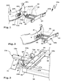
- a load attachment 56 is arranged with a cross member 57 and side rails 58, which also have a total of U, but in opposite directions to the frame or "U" of the Basic carrier 52 is oriented. From the cross member 57 are laterally lights 59. The lights 59 may be pivotable, so that they can be pivoted, for example, to the side rails 58, when the load carrier 50a - 50h is not needed.
- support components and support components may be arranged to support or carry a load to be transported.
- a support 61 is shown, for example, which projects from the longitudinal members 58 at an angle, for example at right angles, when needed.
- the support 61 for example a U-bracket, can be pivoted to the longitudinal members 58 expediently (when not in use). Furthermore, supporting elements 60, for example channels, supporting platforms or the like, are arranged on the load attachment 56, for example pivotably on the longitudinal carriers 58.
- the base support 52 or load attachment 56 provide a support area for carrying a load.
- the load attachment 56 is movably mounted with respect to the base support 52, for example, pivotable, so that it is in an in FIG. 1 indicated loading position 62 from the rear 201 of the motor vehicle 200 is pivotally away.
- a particular telescopic sliding movement is possible, for example, characterized in that the side members 58 are mounted on the longitudinal members 54 slidingly movable.
- the (lower) side members 54 support the (upper) side members 58, ie the side members 58 rest on the side members 54 at least when the motor vehicle 200 or load carrier 50a-50h is being driven.
- load carrier 50a-50h are to be understood merely by way of example, so that, for example, optionally bicycles, a transport box, skis or other objects, Surfboards or the like, on the load carrier 50a - 50h are transportable.
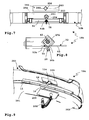
- the vehicle mountings 13a-13h are arranged behind the bumper 202 approximately in the region of a transverse center 203 of the motor vehicle 200, so that not only a central, uniform loading of a basic structure of the motor vehicle 10 performing connection or support of a load carrier is ensured on a motor vehicle , but also a visually optimized connection.
- the bumper 202 has a recess or a cutout 204, which is provided for the attachment of a license plate 206.
- a cutout 205 or a cutout arrangement In the region of the depression or of the cutout 204, there are a cutout 205 or a cutout arrangement, since several, in particular smaller, cutouts can be provided, for example for the vehicle holder 13a-13e, if appropriate also for, for example, further components, eg electrical contacts 14, for example a socket, and / or a coupling arm receptacle 15 (FIG. FIG. 10 ).
- the electrical contacts 14 and the coupling arm receptacle 15 are expediently fastened to the vehicle carrier 11, For example, screwed or welded, so that this as a whole, ie including the vehicle bracket 13a - 13h can be attached as a module on the extent pre-assembled motor vehicle 200.
- the plug-in receptacle of the coupling arm receptacle 15 extends substantially horizontally
- the plug-in receptacle of the coupling arm receptacle 16 is oriented substantially vertically, ie it is open, for example, downwards, towards the road surface or to the ground.
- the mating end of the coupling arm 208 is inserted, for example through an opening 209 at a lower, substantially horizontally extending portion of the bumper 202 therethrough.
- an opening 209 or a cutout on the bumper is required, in particular with this extended approximately in the manner of an apron down in the direction of travel forward.
- the concept shown coupling arm 15 is virtually hidden behind the plate 206, if this conceals the cutout 205 or the cutout arrangement.
- the coupling arm receptacles 15 and 16 are arranged somewhat outside the transverse center 203.
- the coupling arms 207, 208 have in the region of their ball rods adapted gradients or geometries, so that the coupling ball is at about the coupling arm 15, 16 mounted coupling arm 207, 208 approximately in the region of the transverse center 203 of the motor vehicle 200.
- the coupling ball is then arranged quasi across the center directly behind the vehicle mount 13a-13h.
- the tag 206 is attached to a license plate carrier 210.
- the license plate carrier 210 includes, for example, a plate, a support frame or the like, and expediently a not shown in detail holder or holding elements for the plate 206.
- frame-like or plug-like holding means are provided with which the plate 206 on the license plate carrier 210 can be fastened ,
- the license plate 206 it is also possible for the license plate 206 to be screwed to the license plate carrier 210, for example the carrier plate 211 or a frame.
- the carrier plate 211 thus thus the license plate carrier 210, by means of a support bearing 212 pivotally between a release position F, which releases the vehicle holder 13a - 13h for mounting the load carrier 50a - 50h, and a covering position A, in he conceals the vehicle mount 13a - 13h.
- the carrier bearing 212 is, for example, a pivot bearing, such that the license plate carrier 210 and / or the plate 206 between a substantially vertical Position (covering position A) and an angular, for example, horizontal position (release position F) are pivotable.
- the license plate carrier 210 pivots downward into the release position F, so that the fastening arm 51a-51h can be mounted above the license plate carrier 210. Panning upwards is also possible.
- locking means 214 may be provided, for example, include a locking projection on the license plate carrier 210 which engages in a corresponding locking receptacle on the bumper 202.
- the carrier bearing 212 could also have a spring, e.g. a leg spring, be provided, which acts on the support plate or other, the number plate 206 holding component, in the covering position A or the release position F.
- a spring e.g. a leg spring
- a so to speak bidirectional admission into the covering position and the release position or a stop in both positions could take place via a dead center mechanism, with or without a spring.
- the magnetic retaining means 213 may cooperate with ferromagnetic regions on the vehicle mount 13a-13h.
- latching means for example latching projections or latching receptacles, can also be attached to the vehicle mount 13a-13h. be provided, which interact directly with the associated locking means on the license plate carrier 210.
- the carrier bearing 222 comprises, for example, at least one pivot arm 223, which is mounted pivotably on the vehicle side on the one hand by means of a pivot bearing, on the other hand on the license plate carrier 220, for example the carrier plate 221.
- the pivot arm 223 has a curved course, so that the indicator 206 in the release position F quasi down ahead behind the rear 201 of the motor vehicle 200, or behind the bumper 202 vortex.
- the pivotal movement of the pivot arm 223 is advantageously guided in each case by a steering arm 224, which is also mounted on the vehicle side and license plate carrier side each with a pivot or pivot bearing.
- the steering arms 224 have a curved or arcuate course.
- the support plate 221 pivots downward, with an upward pivoting is also possible.
- the carrier bearing 222 is suitably attached to a module which is prefabricated to the other components of the motor vehicle 10 is mounted, for example, on the vehicle carrier eleventh
- the in FIG. 28 illustrated license plate carrier 230 is slidably mounted with respect to the motor vehicle 10. Its carrier plate 211 engages, for example, with its transverse ends in guide receptacles 233 of a carrier bearing 232, which is configured as a sliding bearing.
- the guide receptacles 233 are, for example, U-shaped or have a groove.
- the guide receptacles 233 are expediently also arranged on the vehicle carrier 11 or the vehicle mount 13a-13h. It is understood that even with the license plate carrier 230 holding means, such as latching means or magnetic holding means, are expedient so that the carrier plate 231 remains in the covering position A or release position F.
- locking projections in particular in the interior of their guide grooves, may be provided.
- legs 234 of the guide receptacle 233 which project on the base surface of the support plate 231, so to speak engage in a slot or a gap between the support plate 231 and the plate 206. This is for example approximately transversely in the middle, in particular by means of screws, attached to the support plate 231.
- a frame or other support member for the plate 206 may be provided.
- the license plate carrier 240 ( FIG. 29 ) has on its support plate 241 a lock 242, so that it can be closed, for example, in the covering position A.
- a corresponding lock receptacle 252 or bolt receptacle into which the lock 242 or a closing projection can engage it can be provided, for example, on the bumper 202, but also on a vehicle-side component of the load carrier system 10a-10h, for example the vehicle carrier 11.
- the vehicle-mounted components of the load carrier system 10a - 10h for example, protected against theft or vandalism.
- the lock 242 can of course be used in the other embodiments ( FIGS. 26-28 For example) are used.
- a plug-in projection 250 which fits the vehicle mount 13a or 13b, is provided on the carrier plate 241.
- the plug-in projection protrudes, for example, from the carrier plate 241 on the side facing away from the plate 206 and can be inserted into a corresponding plug-in receptacle.
- a plug-in receptacle 251 may be provided into which the plug-in projection 250 fits.
- the cross member 57 has such a plug receptacle 251.
- the plug-in receptacle 251 advantageously aligns substantially with the vehicle mount 13a or 13b, so that the mark 206 can be fastened transversely in the middle on the load carrier 50a or 50b.
- the plug-in projection 250 forms part of license plate fastening means 253.
- the plug-in receptacle 251 forms part of load carrier fastening means 254, with which the license plate carrier 240 can be attached to the load carrier 50a, 50b.
- the load carrier attachment means 254 also advantageously includes a lock receptacle 252 which cooperates with the lock.
- the lock 242 may enter the lock receptacle 252 when the license plate carrier 240 is attached to the load carrier 50a.
- the plug-in receptacle 251 is not necessary. It is for example the case that the lock 242 and the abutment 255 are provided on mutually diagonal, in each case remote, regions, in particular corner regions, of the license plate carrier or its carrier plate or carrier frame, so that, for example, the carrier plate 241 is hooked into the abutment 255 or in any other way supporting it could fix, while for a tensile, captive and secure hold then the lock 242 cooperates with the lock receptacle 252.
- a gasket may be present which extends for example, sealingly applies to electrical plug-in contacts, a vehicle-side recording or the like, or even, for example, to a surface of the bumper.
- a seal 260 is shown on the plug-in projection 250, for example on its outer circumference, which surrounds the vehicle mount 13a, 13e in the manner of a sealing lip and / or abuts on the end face against it.
- the load carrier systems 10a, 10h each follow a plug-in concept for fastening the load carrier to the motor vehicle.
- the vehicle side transversely central arrangement with in particular only a single mounting arm, wherein the vehicle-mounted bracket can be hidden behind a license plate, of course, allows other fastening concepts, such as screwing, bracing or the like.
- the vehicle mount 13a-13h each comprise plug-in receptacles 17a-17h, which are provided on receiving parts 18a, 18h, for example receiving sleeves.
- Plug-in projections 63a-63h which are provided at the free ends of the fastening arms 51a-51h, can be inserted into the plug-in receptacle 17a-17h.
- Preference is given to a rotationally locking receptacle or a rotationally fixed holder, so that the plug-in receptacle 17a-17h inserted plug projection 63a-63h is held non-rotatably.
- This is expediently already effected by contour design of plug-in receptacle and plug-in projection, in which polygonal or polygonal contours are expedient.
- the load carrier systems 10a, 10b, 10c and 10h rectangular or square cross-sectional inner contours 19 provided on the plug receptacles 17a - 17c, 17h, which also square cross-sectional outer contours 64 on the plug projections 63a - 63c, 63h, positively fit.
- the horizontal support ie the support with respect to forces acting substantially vertically down, are realized in the receiving part 18h and the plug projection 63h by a bottom wall or a bottom side of the plug projection 63h
- the inner contour 19 and outer contour 64 are in the vehicle -Mounts 13a - 13c and the matching, also coupling parts representing mounting arms 51a - 51c quasi on a corner. This allows optimal load distribution, but in particular also a favorable centering of the plug connection between plug-in receptacle 17a-17c and plug-in projection 63a-63c.
- the plug-in projection 63a-63c is thus inserted along a plug-in axis 20 into the associated plug-in receptacle 17a-17c.
- the respective outer corner regions of the plug-in projection 63a-63c engage with corresponding inner corner regions of the plug-in receptacle 17a-17c, inter alia also a lower inner corner region of the inner contour 19, which thus forms a bottom-closed, open-top guide contour or guide groove, and a corresponding one Use of the load carrier system 10a - 10c lower outer corner contour of the outer contour 64 in engagement.
- the inner corner region forms a support receptacle 21, the outer corner region a support projection 65.
- the furthest projecting region of the support projection 65 is that region which absorbs most of the forces acting in the vertical direction, corresponding to that of course next underground area of the support receptacle 21, which accordingly can accommodate most vertical forces.
- the support projection 65 could tilt to the lower bearing point to the side, but then its side walls 66 come to rest on the side walls 22 of the support receptacle 21, are therefore supported laterally. So that's the Anti-rotation ensures, in addition, an optimal centering.
- plug-in projections 63a, 63h are connected to the plug-in receptacles 17a-17h, they can be fixed by means of fixing means 23a-23h, in particular with respect to the respective plug-in axis 20.
- the attachment arm 51a, 51b could, for example, have a bore for receiving the tension rod 68 of the tension anchor 67a, 67b.
- a guide sleeve 71 is provided, which supports the attachment arm 51a, 51b diagonally, i. along the clamping axis 70, interspersed. In the guide sleeve 71 of the pull rod 68 is rotatably received.
- the tensioning element 72a comprises, for example, a toggle-type handle housing in which a clamping nut for screwing onto the aforementioned thread of the tension rod 68 is present.
- the clamping member 72 has a lock 73, with which it can be closed.
- the handle body is torsionally coupled by closing the lock 73 of the inner clamping nut so that it can rotate freely with respect to the clamping nut, but no power transmission in the sense of releasing the tendon 72 can exercise more.
- the retaining groove 27 forms part of an abutment receptacle 28 for the rotationally secure holding of the abutment part 69.
- the abutment 24a is designed to hold with respect to the tensioning axis 70, it is not configured to hold the tensioning anchor 67b in a manner secure against rotation. Rather, a screw thread is provided in which the clamping anchor 67b can be screwed.
- the abutment 24b comprises a nut 29, which is arranged on the receiving part 18b, for example, welded.
- the tendon 72b is on the tension rod 68 of the clamping armature 67b arranged rotationally fixed, so that it virtually forms the head of a screw.
- the tendon 72b is configured as a kind of handle, ie it can be easily grasped and twisted with one hand.
- the tendons 72a, 72b are supported on the guide sleeve 71, so that they exert a clamping force along the clamping axis 70.
- the support projection 65 is pressed into the support receptacle 21 quasi, namely by a perpendicular to the insertion axis 20 force component R, on the other hand, the free end of the male projection 63a, 63b pulled against a longitudinal stop 30 on the receiving part 18a, 18b or .
- Tensioned namely by a parallel to the thru-axle 20 force component P.
- the longitudinal stop 30 and the abutment 24a, 24b are arranged in a preferred embodiment on remote from each other, for example diagonally to each other lying areas with respect to the plug-in axis 20.
- the longitudinal stop 30 is arranged in the interior of the sleeve-like receiving part 18a, 18b on top, while the abutment 24a, 24b arranged below (relative to a horizontal position).
- the abutment 24a, 24b and the longitudinal stop 30 with respect to the plug-in axis 20 have a longitudinal distance from one another, which leads quasi to a tilting and tilting of the plug projection 63a, 63b in the plug receptacle 17a, 17b.
- abutment 24a, 24b defined thereby, so to speak, a tilting point or pivot point about which the plug projection 63a, 63b can pivot by a certain, very small amount (arrow S), at least can swing so far until its free end abuts the longitudinal stop 30.
- An embodiment not shown in the drawing may provide that the free end of a male projection substantially flat, ie can strike in several rotational angle positions with respect to the plug-in axis or plug center axis. In the embodiments, however, an off-center or away from the thru-axle position for the longitudinal stop 30 is selected.
- the free end of the plug-in projection 63a, 63b thus does not strike the entire surface of a longitudinal stop, but only partially, the arrangement is advantageously made so that a longitudinal stop portion 75, with which the plug projection 63a abuts the longitudinal stop 30, and an abutment portion 74, for example the exit region of the clamping armature 67a, 67b from the attachment arm 51a, 51b, on opposite sides with respect to the plug-in axis 20 and the plug center axis or the respective axis containing plane lies.
- the receiving parts 18a-18h are screwed, welded or glued to the vehicle carrier 11, for example. You can also enforce a respective vehicle carrier 11, which is preferably designed as a tube, in particular polygonal tube, or arranged on a side wall. For example, additional supports 31 are present in the vehicle mount 13a, the forces occurring during driving optimally and at several geometrically distant points on the vehicle carrier 11 initiate.
- the subsequent latching and securing concept implemented in the load carrier system 10b could, of course, not only be used with the plug system provided with a tension anchor diagonal course, for example also with the load carrier system 10a, but also with additional securing elements and fixing elements in another form Systems, for example in the nature of the load carrier system 10c.
- the locking member 32 comprises a spring element 33 which is provided with a holding portion 34 fixed to the receiving part 18 b and from which a latching portion 35 springs protrudes.
- the holding portion 34 is for example U-shaped, with its side legs, one of which merges into the latching portion 35, are inserted into receptacles 36 of a holder 37.
- the receptacles 36 are arranged on a support leg 38 of the holder 37 and facing away from each other open.
- the support leg 38 is, for example, angled, for example at right angles, from a support 39, which is designed in the manner of a retaining plate.
- the carrier 39 is connected to the vehicle carrier 11 and / or the vehicle holder 13b, for example, welded.
- the latching section 35 protrudes into the plug-in receptacle 17b.
- the latching section 35 protrudes into a recess 40 on the receiving part 18b, so that it is arranged tangentially in the plug-in receptacle 17b.
- a bevel 77 at the front, free end of the plug projection 63b displaces the latch section 35, which is resilient, out of the socket 17b.
- the example rod-like or rod-like latching portion 35 then slides along the outer circumference of the plug projection 63b until the locking receptacle 76 on the plug projection 63b in the area in the recess 40 suitably guided spring element 33 and latching portion 35 and thus the latching portion 35 can snap into the latching receptacle 76 resiliently ,
- the latching section 35 then forms a stop section, since the plug projection 63b abuts against the side walls of the latching receptacle 76 on the latching section 35.
- the plug-in projection 63b can not unintentionally get out of the plug-in receptacle 17b.
- a locking is given, which is also a security function Fulfills.
- the subsequent tightening for example, hooking the clamping anchor 67a or 67b in the associated abutment 24a, 24b is very simple, since the components are already prepositioned to each other.
- locking pin or latching projection may be provided which is spring loaded in its locking or securing position and, for example, by pulling or pressing or other operation from its locking and securing position can be brought into a release position.
- FIGS. 7 and 8 A particularly simple concept for the production of electrical contacts between motor vehicle and load carrier is in the FIGS. 7 and 8 shown.
- electrical contacts are provided, in particular on a contact carrier 42.
- the receiving part 18a, 18b, as I said sleeve-like, so that the contact carrier 42 can be accommodated protected in the interior formed thereby.
- the plug-in projection 63a, 63b is expediently tube-like or sleeve-like, so that there is also a receiving space for a contact carrier 78.
- the plug-in projections 63a, 63b in the plug-in receptacles 17a, 17b reach the contacts on the contact carriers 42, 78 with each other in electrical connection.
- the one contacts are designed as contact projections, the other contacts as contact sockets or have such respectively.
- the plug-in projection 63c and the plug-in receptacle 17c have rectangular or square outer and inner contours.
- the plug-in receptacle 17c is provided on the sleeve-like receiving part 18c.
- an off-center longitudinal stop 30 is provided on the receiving part 18c.
- the longitudinal stop 30 and an abutment region or clamping region of the receiving part 18c are provided with respect to the plug-in axis 20 with a longitudinal distance from each other, which may advantageously cause a certain tilting or tilting in terms of optimized bracing.
- the abutment region 43 is arranged for example on a support sleeve 44, which in turn is arranged against rotation at the free end of the receiving part 18c, for example, welded or glued or screwed.
- a support sleeve 44 which has a thread
- a rotatably mounted on the mounting arm 51c cap sleeve 79 is screwed, which on the thread on the support sleeve 44th can be screwed on.
- the two threads form form-fitting contours and counter-form-fitting contours.
- cap sleeve 79 is rotatable and displaceable to some extent with respect to the plug-in axis 20, which also represents a clamping axis, but only up to an end stop, not shown. This makes it possible that by tightening the cap sleeve 79 on the support sleeve 44 of the mounting arm 51c is clamped to the vehicle bracket 13c.
- a longitudinal offset between the abutment area (abutment area 43) and the longitudinal stop (e.g., longitudinal stop 30) will provide improved bracing, even if there is no tie-bolt diagonally acting, e.g. the tension anchor 67a or 67b.
- the longitudinal stop 30 with respect to a free end of the plug-in receptacle 17 c with respect to the plug-in axis 20 axially offset.
- the longitudinal stop 30 is disposed above a horizontal plane, under the support projection 65 and the support receptacle 21, which also causes a diagonal-tensioning effect, therefore, a tilting of the plug projection and plug-in receptacle together.
- an optimal grip is possible.
- a cap sleeve is likewise provided which is rotatably and displaceably mounted on the attachment arm 51d.
- the plug-in projection 63d like the mating plug-in receptacle 17d, is round, for example circular. As a result, in principle, a rotation of the two components relative to each other is possible.
- a stop recess 81 is present, which comprises only a partial circle circumference or partial circumference of the plug-in projection 63d.
- stop recess 81 rotational stops 83, which engage against a stop element 45 in the interior of the plug-in receptacle 17d against rotation.
- the stop member 45 thus forms a rotation stop.
- the stop element 45 is formed by a transverse pin 46, which is positioned in the manner of a secant.
- rotational stops 83 is followed by serving as a longitudinal stop slope 82 at.
- the bevel 82 slides along the stop element 45 and also on it, so that a distortion of the two components is caused to each other, especially if the cap sleeve 80 on a thread 47 on the receiving part 18d is screwed.
- the attachment arm 51a, 51b is connected to the base support 52 by means of a U-shaped receptacle in which the cross member 53 engages
- the attachment arm 51d is connected to the cross member 53 by a flange 48.
- a bearing similar in relation to the "central" support bearing by means of a support receptacle and a support projection is realized as in couplings with vehicle mount and mounting arm of the load carrier systems 10a, 10b, however, so to speak kinematic reversal.
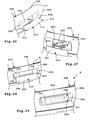
- the plug-in receptacle 17e and the plug-in projection 63e are designed in the manner of a dovetail connection.
- the plug-in receptacle 17e comprises a support projection 49 for engagement in a support receptacle 84 on the plug-in projection 63e.
- the plug-in axis 20 extends at the plug connection of the load carrier system 10e transversely, for example at right angles, to the longitudinal direction of the attachment arm 51e.
- a plate 110 of the vehicle mount 13e has a end abutment surface 111 for abutment of a plate 112, which is arranged at the free end of the mounting arm 51e.
- the plates 110, 112 are in the mounted coupling (plug projection 63e on vehicle mount 13e) substantially flat against each other, so that thereby an optimal support of the two components is guaranteed to each other.
- the support projection 49 has two angularly extending, for example, roof edge-like support surfaces 113.
- the support surface 113 form groove bottoms of grooves, which is bounded on the one hand by the plate 110, on the other hand by a guide plate 114.
- the guide plate 114 extends parallel to the plate 110.
- the guide plate 114 and the plate 110 thus define between them receiving grooves whose groove bottom is formed by the roof edge-like support surfaces 113.
- the guide plate 114 has a correlating to the support surfaces 113 contour, so is also (inside) roof-like.
- the plate 112 has a thickness such that it fits into the space between the plate 110 and the guide plate 114, as possible form-fit and with little play.
- additional fixation clamping and locking means may be provided, for example, a strain in the nature of the clamping anchors 67a, 67b realized clamping or even, for example, a latch 116 which locks the plug connection between plug projection 63e and plug receptacle 17e.
- the latch 116 could be pivoted over the two nested components ( FIG. 17 ), so that it acts as a locking connection for the plug-in projection 63 e, so that it can not be pulled out in the direction of the plug-in axis 20 from the plug-in receptacle 17 e.
- a plug-in projection 63f is inserted into a vehicle-side plug-in receptacle 17f.
- An eccentric tensioning lever 120 is arranged on the vehicle mount 13f, which acts, for example, on a transverse bolt which is not visible in the drawing and which passes through the insertion projection 63f in the sense of tensioning.
- the eccentric clamping lever 120 exerts a transverse force transversely to the plug-in axis 20, such that it acts, for example, in the sense of narrowing the plug-in receptacle 17f and thus clamps the plug-in projection 63f in the plug-in receptacle 17f.
- FIGS. 20, 21 illustrated load carrier system 10g uses a known from towbars locking and plug concept.
- the coupling arm 207 may be locked to the coupling receptacle 15 with a similar locking technique.
- the plug-in receptacle 17g comprises form-locking grooves 130 extending transversely to the plug-in axis 20, for example round grooves which enable a rotationally-locked connection of the fastening arm 51g in the vehicle mount 13g.
- form-fitting projections 131 engage positively, which have to the form-fitting grooves 130 matching peripheral contours.
- the form-fitting projections 131 are formed, for example, by a transverse bolt, which passes through the fastening arm 51g transversely to the plug-in axis 20, for example at right angles.
- a rotationally engaging reception of the plug projection 63g in the plug-in receptacle 17g is also possible if, as in the present case, both components have per se round circumferential contours, so that they can be rotated relative to one another.
- a blocking element such as a bolt 132, approximately slidably mounted along the plug-in axis 20, wherein it displaces radially outwardly in front of an outer periphery of the plug projection 63g in a blocking position balls 133 or other form-fitting body, so that these in a form-locking receptacle 134th , For example, a groove or circumferential groove, engages positively in the interior of the plug-in receptacle 17g.
- the plug-in projection 63g is secured against being pulled out of the plug-in receptacle 17g and is also braced into it.
- an actuating lever 135 is coupled in motion via a gear, such as a toothed gear, with the bolt 132.
- load carrier system 10h is a plug-in and locking concept realized, which of course also in load carriers and associated vehicle mounts can be used, which have a plurality of mounting arms and associated brackets on the vehicle.
- the outer contour of the plug-in projection 63h and the inner contour of the plug-in receptacle 17h are each polygonal, in this case, for example, square. The arrangement is such that the plug projection 63h rests flat on a bottom surface of the plug receptacle 17h.
- the plug projection 63h has inside a receiving space in which a holding forceps 140 is received.
- Pliers parts 141 of the holding pliers 140 are pivotable relative to each other by means of a pivot bearing 142.
- the bearing pin 143 is expediently in the direction of the pivot axis of the pivot bearing 142, so that it can penetrate into an upper and / or a lower side wall 144 of the plug projection 63 h.
- the retaining pliers 140 are received immovably with respect to the plug-in axis 20 in the plug-in projection 63h.
- An expedient measure can provide that the bearing pin 143 even penetrates the side walls 144, ie protrudes outward therefrom, so that it can simultaneously form a positive locking projection which can form-fitly engage in a positive locking receptacle 145 on the plug receptacle 17h, for example on its end side ,
- This measure is optional. Due to the polygonal cross section of the plug-in receptacle 17h and the plug-in projection 63h, an additional positive connection is not necessary.
- a form-fitting projection protruding fixedly in front of the side walls 144 may be provided, for example with this one-piece form-fitting projection.
- the pliers members 141 each include an actuating arm 146 and a retaining arm 147 disposed on opposite sides with respect to the pivot bearing 142.
- the two actuating arms 146 are acted upon by a spring 148 away from each other, so that mutatis mutandis, the holding arms 147 are acted upon by the spring 148 away from each other.
- the pliers 141 are spread by the spring 148 quasi away from each other. It is understood that a spring would also be possible between the holding arms 147.
- each of the pliers parts 141 is supported by a separate spring on the insertion projection 63h, so that the pliers parts 141 in this way the in FIG. 23 take blocking position B shown.
- actuating arms 146 operable by an operator operating areas 149 are provided, ie on opposite sides of the actuating arms 146.
- the actuating arms 146 are available with their operating areas 149 in Betsch Trentsaus Principlelessness 150, so that an operator can take them, in particular can push.
- By actuating the actuating arms 146 in the direction of the actuating recesses 150 they enter into an insertion or unlocking position E (FIG. FIG. 24 ), in the retaining contours 151 on the support arms 147 pass through openings 152 on the insertion projection 63h and protrude so far in front of an outer surface of the insertion projection 63h that they are in engagement with Schmidthaltekonturen 153 on the plug receptacle 17h.
- the counter-holding contours 153 are formed by holding receptacles 154, in which the holding contours 151 engage in the blocking position B.
- the holding receivers 154, the passage openings 152 and the actuating recesses 150 are each arranged in pairs on mutually opposite side walls of the plug-in receptacle 17h and of the plug-in projection 63h.
- the passage openings 152 and the holding receivers 154 are, for example, elongated holes, matching the outer contours or passage contours of the holding forceps 140, which are each provided for engagement in the respective recess. It is understood that other geometries of the recesses are also possible.
- the retaining seats 154 are in the region of the retaining contours 151, they come free and engage in the retaining seats 154. Then strike latch surfaces 157 at the longitudinal ends 158 (relative to the plug-in axis 20) of the holding receptacles and act in the sense of a Verhakens such that a withdrawal of the male projection 63h is blocked from the plug receptacle 17h.
- An embodiment, not shown in the drawing can provide that the locking surfaces 157 are chamfered so that they form clamping surfaces, which cause a distortion of the male projection 63h in the socket 17h.
- passage openings 152 are not absolutely necessary. Rather, for example, a holding arm 147 or both holding arms 147 projecting freely in front of the free end of the plug projection 63h (not shown) and yet be configured to engage in the holding receptacles 154.
- the locking surface 157 may cooperate in its design as a clamping surface, for example, with the free end of the bearing pin 143 which engages in the form-fitting receptacle 145, in the sense of clamping, i. that the locking surfaces 157 pull or clamp in a function as clamping surfaces the "positive locking projection" of the bearing pin 143 in the form-fitting receptacle 145 into it.
- the bearing pin 143 is provided with respect to the plug-in axis 20 to fix the retaining pliers 140 fixed to the insertion projection 63h.
- This function can also fulfill, for example, the actuating arms 156, at least in the sense of a support: On the actuating arms 146 namely stop surfaces 159 are formed, which abut longitudinal stops 160 of the plug projection 63 h.
- the longitudinal stops 160 are formed, for example, by the longitudinal ends of the Betuschistsaus Principle 150.
- the stop surfaces 159 are arranged, for example, on the actuating regions 149, which are designed as projections.
- the stop surfaces 159, 160 extend transversely to the plug-in axis 20, which also forms a clamping axis or locking axis for the holding forceps 140.
- the holding receptacle 161 is designed, for example, as an insertion opening or as a receiving groove.
Abstract
Description
Die Erfindung betrifft ein Lastenträger-System für ein Kraftfahrzeug, mit mindestens einer an einem Fahrzeug-Träger angeordneten Fahrzeug-Halterung zur Befestigung an einem Heck des Kraftfahrzeugs und mit einem Lastenträger, der einen Tragbereich zum Tragen einer Last aufweist, von dem mindestens ein Befestigungsarm zur Befestigung an der mindestens einen Fahrzeug-Halterung absteht, und mit Fixiermitteln, mit den der mindestens eine Befestigungsarm an der mindestens einen Fahrzeug-Halterung fixierbar ist.The invention relates to a load carrier system for a motor vehicle, comprising at least one arranged on a vehicle carrier vehicle mount for attachment to a rear of the motor vehicle and with a load carrier having a support portion for carrying a load from the at least one mounting arm for Mounting on the at least one vehicle support protrudes, and with fixing means with which the at least one mounting arm to the at least one vehicle mount is fixable.
Ein derartiges Lastenträger-System geht beispielsweise aus
Davon ausgehend ist es die Aufgabe der vorliegenden Erfindung ein Lastenträger-System mit einem möglichst einfach handhabbaren Lastenträger bereitzustellen.On this basis, it is the object of the present invention to provide a load carrier system with a load carrier which is as easy to handle as possible.
Zur Lösung der Aufgabe ist bei einem Lastenträger-System der eingangs genannten Art vorgesehen, dass die mindestens eine Fahrzeug-Halterung an dem an dem Kraftfahrzeug angeordneten oder anordenbaren Fahrzeug-Träger derart angeordnet ist, dass sie bei am Kraftfahrzeug angeordnetem Fahrzeug-Träger im Bereich einer Quermitte des Kraftfahrzeugs hinter einem Kennzeichen und/oder hinter einem Stoßfänger des Kraftfahrzeugs angeordnet ist.To solve the problem is provided in a load carrier system of the type mentioned that the at least one vehicle mount is arranged on the arranged or arranged on the motor vehicle carrier such that it is arranged on the vehicle vehicle carrier in the area Transverse center of the motor vehicle is arranged behind a license plate and / or behind a bumper of the motor vehicle.
Die Erfindung betrifft ferner einen Lastenträger der einen Bestandteil eines solches Lastenträgersystemes bilden kann, also zu einer quermittigen Anwendung an das Kraftfahrzeug ausgestaltet ist, sowie ferner die fahrzeugseitig zu montierenden Komponenten, das heißt den Fahrzeug-Träger, der die erfindungsgemäß angeordnete Fahrzeug-Halterung aufweist.The invention further relates to a load carrier which may form part of such a load carrier system, that is configured for a transverse application to the motor vehicle, as well as the components to be mounted on the vehicle side, ie the vehicle carrier having the vehicle mount arranged according to the invention.
Bei beiden Komponenten ist es typisch, dass sie im am Kraftfahrzeug montierten Zustand einen verhältnismäßig großen Abstand von einem Untergrund, beispielsweise der Fahrbahn haben. Beispielsweise ist der Lastenträger so getroffen, dass er einen quermittigen oder mehrere quermittige Befestigungsarme hat, an dem dann der Tragbereich, beispielsweise eine Tragplattform, ein Tragegestell oder dergleichen, angeordnet ist.In both components, it is typical that they have a relatively large distance from a substrate, for example the road surface when mounted on the motor vehicle. For example, the load carrier is made such that it has one or more transverse center attachment arms on which the support area, for example a support platform, a support frame or the like, is arranged.
Eine bevorzugte Ausführungsform der Erfindung sieht vor, dass der Lastenträger nur einen einzigen Befestigungsarm und der Fahrzeugträger nur eine einzige Fahrzeug-Halterung aufweisen. Prinzipiell wäre es auch denkbar, dass beispielsweise zwei oder mehr relativ schmal beieinander angeordnete Befestigungsarme vorgesehen sind.A preferred embodiment of the invention provides that the load carrier only a single mounting arm and the vehicle carrier have only a single vehicle mount. In principle, it would also be conceivable that, for example, two or more relatively narrow arranged mutually fastening arms are provided.
An der Fahrzeug-Halterung und dem Befestigungsarm sind zweckmäßigerweise elektrische Fahrzeug-Kontakte und elektrische Lastenträger-Kontakte zur Herstellung einer elektrischen Verbindung zwischen dem Kraftfahrzeug und dem Lastenträger vorgesehen. Dies hat insbesondere dann große Vorteile, wenn nur ein einziger Befestigungsarm vorhanden ist. Mit dem Anstecken oder Anbinden des eine Befestigungsarms an die eine Fahrzeug-Halterung ist somit nicht nur die mechanisch belastbare Verbindung zwischen Kraftfahrzeug und Lastenträger hergestellt, sondern auch gleichzeitig eine elektrische Verbindung. Über die vorgenannte elektrische Verbindung ist beispielsweise eine Bus-Verbindung möglich. Bevorzugt können somit beispielsweise elektrische Stromverbraucher, z.B. Heckleuchten, am Lastenträger vom Bordnetz des Kraftfahrzeuges mit versorgt werden.At the vehicle mount and the mounting arm electrical vehicle contacts and electrical load carrier contacts are expediently provided for producing an electrical connection between the motor vehicle and the load carrier. This has great advantages in particular if only a single attachment arm is present. Thus, not only the mechanically load-bearing connection between the motor vehicle and the load carrier is produced with the attachment or attachment of the one fastening arm to the one vehicle mount, but also at the same time an electrical connection. About the aforementioned electrical connection, for example, a bus connection is possible. Thus, for example, electrical power consumers, e.g. Taillights, be supplied to the load carrier from the electrical system of the motor vehicle.
Eine geschützte Anordnung der Fahrzeug-Kontakte und Lastenträger-Kontakte sieht vor, dass sie in einem Innenraum der Fahrzeug-Halterung und des Befestigungsarms angeordnet sind, so dass sie eingehaust sind, wenn der Befestigungsarm an der Fahrzeug-Halterung befestigst ist. Somit bilden also die Fahrzeug-Halterung und/oder der Befestigungsarm beispielsweise ein Schutzgehäuse für die Lastenträger-Kontakte bzw. die Fahrzeug-Kontakte, wenn das System im Einsatz ist.A protected arrangement of the vehicle contacts and load carrier contacts provides that they are arranged in an interior of the vehicle mount and the mounting arm, so that they are housed when the mounting arm is fastened to the vehicle mount. Thus, for example, the vehicle mount and / or the attachment arm form, for example, a protective housing for the load carrier contacts or the vehicle contacts when the system is in use.
An dem Fahrzeuge-Träger ist zweckmäßigerweise eine Kupplungsarm-Aufnahme oder ein Kupplungsarm-Lager für einen Kupplungsarm einer Anhängekupplung angeordnet. Mit dem Lager kann der Kupplungsarm beispielsweise schwenkbeweglich und/oder schiebebeweglich gelagert sein. Somit hat der Fahrzeug-Träger also eine Doppelfunktion: er trägt der Lastenträger und zusätzlich die Kupplungsarm-Aufnahme, somit also gegebenenfalls den Kupplungsarm, wenn eine Anhängekupplung benötigt wird.On the vehicle carrier expediently a coupling arm receptacle or a coupling arm bearing for a coupling arm of a trailer coupling is arranged. With the bearing, the coupling arm can be mounted, for example, pivotally and / or slide-movable. Thus, the vehicle carrier has a double function: it carries the load carrier and in addition the coupling arm receptacle, thus thus optionally the coupling arm when a trailer coupling is needed.
An der mindestens einen Fahrzeug-Halterung und dem mindestens einen Befestigungsarm sind zweckmäßigerweise Steckmittel zum Anstecken des mindestens einen Befestigungsarms an die mindestens eine Fahrzeug-Halterung entlang einer Steckachse vorgesehen, wobei die Steckmittel eine Steckaufnahme und einen Steckvorsprung umfassen. Somit kann also beispielsweise ein freies Ende des Befestigungsarms einen Steckvorsprung bilden, die Fahrzeug-Halterung eine Steckaufnahme ausbilden oder aufweisen. Es ist aber umgekehrt denkbar, dass nämlich am Befestigungsarm eine Steckaufnahme vorhanden ist, die auf einen korrespondierenden Steckvorsprung an der Fahrzeug-Halterung aufgesteckt wird.On the at least one vehicle mount and the at least one attachment arm plug-in means are expediently provided for attaching the at least one attachment arm to the at least one vehicle mount along a plug-in axis, wherein the plug means comprise a plug receptacle and a plug projection. Thus, for example, a free end of the mounting arm can form a plug-in projection, the vehicle mount can form or have a plug-in receptacle. But it is conceivable vice versa, namely that a plug-in receptacle is present on the mounting arm, which is attached to a corresponding plug-in projection on the vehicle mount.
An dieser Stelle sei bemerkt, dass selbstverständlich eine verdrehsichere Montage zweckmäßig ist, das heißt, dass an der Fahrzeug-Halterung und an dem Befestigungsarm Dreh-Blockiermittel oder Formschlusskonturen vorhanden sind, mit denen der Lastenträger verdrehsicher am Fahrzeug-Träger montierbar ist. Diese Dreh-Fixiermittel können Bestandteile der vorgenannten Fixiermittel bilden.At this point it should be noted that, of course, a rotationally secure assembly is appropriate, that is, on the vehicle mount and on the mounting arm rotational blocking means or form-fitting contours are available, with which the load carrier against rotation on the vehicle carrier can be mounted. These rotary fixing means may form constituents of the aforementioned fixing means.
Eine bevorzugte Ausführungsform der Erfindung sieht vor, dass die Fixiermittel einen quer zur Steckachse wirkenden und verlaufenden Spannanker aufweisen. Der Spannanker ist an einem Widerlager gehalten, der an der Steckaufnahme oder dem Steckvorsprung angeordnet ist. Der Spannanker stützt sich mit einem Spannglied, beispielsweise einer Spannmutter, am jeweils anderen Bauteil, also dem Steckvorsprung oder der Steckaufnahme ab, so dass durch Spannen des Spanngliedes der Steckvorsprung mit der Steckaufnahme verspannbar ist. Durch den quer zur Steckachse wirkenden Spannanker, beispielsweise diagonal wirkenden Spannanker, ist eine optimale Verspannung möglich.A preferred embodiment of the invention provides that the fixing means have a clamping armature acting and extending transversely to the plug-in axis. The clamping anchor is held on an abutment which is arranged on the plug-in receptacle or the plug-in projection. The clamping armature is supported by a clamping member, for example a clamping nut, on the respective other component, that is to say the plug projection or the plug-in receptacle, so that the plug projection can be clamped by clamping the tension member. By acting transversely to the thru axle clamping anchor, such as diagonally acting clamping anchor, optimal tension is possible.
Der Spannanker durchdringt beispielsweise den Steckvorsprung oder die Steckaufnahme oder beides, beispielsweise diagonal zur Steckachse. Bevorzugt ist für den Spannanker eine Führungshülse angeordnet, die den entsprechenden Querverlauf oder Diagonalverlauf hat. Somit ist der Spannanker beispielsweise in dieser Hülse drehbar gelagert.The tension anchor penetrates, for example, the plug-in projection or the plug-in receptacle or both, for example diagonally to the plug-in axis. Preferably, a guide sleeve is arranged for the clamping anchor, which has the corresponding transverse course or diagonal course. Thus, the clamping anchor is rotatably mounted, for example, in this sleeve.
Das Widerlager und ein Längsanschlag des Steckvorsprungs oder der Steckaufnahme sind bezüglich der Steckachse drehwinkelversetzt. Beispielsweise sind das Widerlager und der Längsanschlag an einander entgegengesetzten Seiten des Steckvorsprung oder der Steckaufnahme angeordnet. Somit ist also ein optimales Spannkonzept realisiert, das heißt dass der Spannanker den Steckvorsprung mit der Steckaufnahme schräg und quer zur Steckachse verspannt. Eine gewisse Asymmetrie der Spannkräfte ist somit gegeben, die vorteilhaft auf den formschlüssigen und sicheren Halt der Lastenträgers am Fahrzeug-Träger sorgt.The abutment and a longitudinal stop of the plug-in projection or the plug-in receptacle are offset in angle of rotation relative to the plug-in axis. For example, the abutment and the longitudinal stop are arranged on opposite sides of the plug-in projection or the plug-in receptacle. Thus, therefore, an optimal clamping concept is realized, that is, that the clamping anchor clamps the plug projection with the plug-in receptacle obliquely and transversely to the plug-in axis. A certain asymmetry of the clamping forces is thus given, which advantageously ensures the positive and secure grip of the load carrier on the vehicle carrier.
Der Fahrzeug-Träger wird beispielsweise von einem Querträger gebildet oder umfasst einen solchen, der an der Karosserie des Kraftfahrzeuges befestigbar ist.The vehicle carrier is formed, for example, by a cross member or includes one which can be fastened to the body of the motor vehicle.
Das Widerlager umfasst zweckmäßigerweise mindestens eine Widerlageraufnahme zur verdrehsicheren Aufnahme eines Widerlagerteils des Spannankers. Bevorzugt ist dabei die Anordnung so getroffen, dass das Widerlagerteil von der Widerlager-Aufnahme lösbar ist, so dass der Spannanker quasi aus dem Widerlager ausgehängt werden kann, wenn der Lastenträger vom Kraftfahrzeug entfernt werden soll. Es versteht sich, dass als Widerlager beispielsweise auch eine Schraubaufnahme möglich ist.The abutment expediently comprises at least one abutment receptacle for the rotationally secure reception of an abutment part of the clamping anchor. Preferably, the arrangement is made such that the abutment part of the abutment receptacle is detachable, so that the clamping anchor can be quasi suspended from the abutment when the load carrier is to be removed from the motor vehicle. It is understood that as an abutment, for example, a screw is possible.
An einander entgegengesetzten Längsendbereichen eines Zugstabes des Spannankers sind einerseits das vorgenannte Widerlagerteil, andererseits vorteilhaft eine Gewinde angeordnet, auf das beispielsweise ein Spannglied aufschraubbar ist. Dieses Spannglied ist vorzugsweise verschließbar. Somit kann also durch Verschließen des Spanngliedes der Lastenträger am Kraftfahrzeug gesichert werden.At opposite longitudinal end portions of a tension rod of the clamping anchor on the one hand, the aforementioned abutment part, on the other hand, advantageously arranged a thread on the For example, a tendon is screwed. This tendon is preferably closable. Thus, so can be secured by closing the tendon of the load carrier on the motor vehicle.
Die Steckaufnahme und/oder der Steckvorsprung umfassen beispielsweise ein Rastglied und/oder ein Sicherungsglied, mit denen das eine Bauteil am anderen Bauteil verrastbar ist, bzw. sicherbar. Bevorzugt ist dabei eine Art Vorverrastung, das zusätzlich zu dem Rastglied oder Sicherungsglied Spannmittel vorgesehen sind. Das Rastglied oder Sicherungsglied sorgt dafür, dass der Steckvorsprung an der Steckaufnahme gehalten wird, beispielsweise um anschließend ein Verspannen, beispielsweise mit den vorgenannten Zuganker oder sonstigen Sicherungsmaßnahmen, vorzunehmen. Das Sicherungsglied bildet eine zusätzliche Maßnahme, die nicht notwendig ist, aber vorteilhaft. Selbst wenn die Verspannung ausfällt, wirkt noch das Sicherungsglied, so dass der Lastenträger jedenfalls nicht verlorengeht.The plug-in receptacle and / or the plug-in projection comprise, for example, a latching element and / or a securing element, with which one component can be latched to the other component, or can be secured. Preference is given to a kind Vorverrastung, which are provided in addition to the locking member or securing member clamping means. The locking member or securing member ensures that the plug-in projection is held on the plug-in receptacle, for example, then to make a bracing, for example with the aforementioned tie rods or other safety measures. The securing member forms an additional measure which is not necessary, but advantageous. Even if the tension fails, still acts the locking member, so that the load carrier is not lost in any case.
Das Vorsehen eines zusätzlichen Rastgliedes und/oder Sicherungsglieds zusätzlich zu Spannmitteln bei der Befestigung eines Lastenträgers an einer Fahrzeug-Halterung stellt eine an sich eigenständige Erfindung dar. Auf die konkrete Ausgestaltung der Spannmittel wie später noch in der Zeichnung dargestellt, beispielsweise mittels einer Spannschraube, kommt es nicht an. Es können durchaus auch andere Spannmittel vorgesehen sein, beispielsweise ein Exzenterspannglied, das von außen her auf die Verbindung zwischen Steckvorsprung und Steckaufnahme wirkt, um die beiden Bauteile miteinander zu verspannen. Weiterhin könnte auch ein Spannanker vorgesehen sein, der in Richtung der Steckachse wirksam ist, das heißt nicht quer zu dieser verläuft. Selbstverständlich kann das Rastglied oder Sicherungsglied auch von einer später noch beschriebenen Spannzange gebildet sein oder Haltzange gebildet sein. Zusätzlich zu dieser Haltezange kann selbstverständlich das vorgenannte Rastglied oder Sicherungsglied vorgesehen sein.The provision of an additional locking member and / or securing member in addition to clamping means in the attachment of a load carrier to a vehicle mount is an independent invention. On the specific design of the clamping means as shown later in the drawing, for example by means of a clamping screw comes it does not matter. It may well be provided other clamping means, such as an eccentric clamping member which acts from the outside on the connection between the male projection and the plug-in receptacle to clamp the two components together. Furthermore, a clamping armature could be provided which is effective in the direction of the thru-axle, that is not transverse to this. Of course, the locking member or securing member may also be formed by a later-described collet chuck or formed. In addition to this holding forceps can Of course, the aforementioned locking member or securing member may be provided.
Das Rastglied und/oder das Sicherungsglied umfassen beispielsweise ein Federelement, das einen Anschlagabschnitt aufweist, der zum Verrasten oder Sichern vorgesehen ist und in der Steckaufnahme, beispielsweise tangential, verläuft. Zusätzlich hat das im Bereich des Anschlagabschnitts zweckmäßigerweise stabförmige Federelement einen Betätigungsabschnitt, der seitlich vor die Steckaufnahme zur Betätigung des Federelements im Sinne eines Entrastens oder Entsicherns vorsteht. Somit kann also das Federelement ausgelenkt werden, so dass der Rasteingriff oder Sicherungseingriff des Anschlagabschnittes ausgehoben ist. Bevorzugt greift der Anschlagabschnitt formschlüssig in den Steckvorsprung bzw. einer dort angeordneten Rastaufnahme oder Sicherungsaufnahme, ein.The latching member and / or the securing member comprise, for example, a spring element which has a stop portion which is provided for latching or securing and extends in the plug-in receptacle, for example tangentially. In addition, in the region of the abutment portion suitably rod-shaped spring element has an actuating portion which protrudes laterally in front of the plug-in receptacle for actuating the spring element in the sense of Entrastens or Entsicherns. Thus, therefore, the spring element can be deflected, so that the latching engagement or securing engagement of the stop portion is dug. Preferably, the stopper section engages positively in the plug-in projection or a latching receptacle or securing receptacle arranged there.
Die Steckaufnahme und der Steckvorsprung verlaufen zweckmäßigerweise bei üblichem Gebrauch etwa horizontal. Somit weisen auch die Steckachse vorteilhaft einen horizontalen Verlauf auf. Der Bediener muss also bei dieser Ausführungsform den Lastenträger nicht etwa von oben nach unten oder schräg betätigen, um die Verbindung zum Kraftfahrzeug bzw. der Fahrzeug-Halterung herzustellen, sondern kann den Lastenträger horizontal führen. Dies ist besonders komfortabel. Allerdings ist festzuhalten, dass bezüglich des vorgenannten Rastkonzepts, Sicherungskonzepts oder auch der Spannmittel selbstverständlich auch eine schrägstehende oder vertikale Steckachse denkbar sind.The plug-in receptacle and the plug-in projection advantageously extend approximately horizontally in normal use. Thus, the plug-in axis advantageously have a horizontal course. In this embodiment, therefore, the operator does not have to operate the load carrier from above to below or obliquely in order to establish the connection to the motor vehicle or the vehicle mount, but can guide the load carrier horizontally. This is especially comfortable. However, it should be noted that with respect to the aforementioned locking concept, safety concept or the clamping means of course, a tilted or vertical plug-in axis are conceivable.
Eine an sich eigenständige Erfindung im Zusammenhang mit dem Anstecken eines Lastenträgers an eine Fahrzeug-Halterung stellt das Nachfolgende dar. Es kommt dabei nicht darauf an, dass der Lagerträger eine quermittige Anbindung an das Kraftfahrzeug hat. Vielmehr könnte auch eine außerhalb der Quermitte vorgesehene Anbindung, beispielsweise eine gabelartige Anbindung, wie beispielsweise in
Im Innern der Steckaufnahme oder des Steckvorsprungs ist zweckmäßigerweise eine Haltezange angeordnet. Die Haltezange hat Haltekonturen beispielsweise Haltevorsprünge oder Halteausnehmungen. Im andern Bauteil, das heißt dem Steckvorsprung oder der Steckaufnahme, sind dazu passende Gegenhaltekonturen vorgesehen, z.B. Halteaufnahmen oder auch Haltevorsprünge, die zum Eingriff mit den Haltekonturen vorgesehen sind. Die Zange weist Zangenteile auf, die mittels eines Schwenklagers relativ zueinander verschwenkbar sind, durch eine Feder jedoch in eine Blockierstellung beaufschlagt sind. Beispielsweise stützt sich die Feder an einander zugewandten Innenseiten der Haltezange bzw. der Zangenteile ab. Die Feder bewirkt, dass die Haltekonturen beim Einstecken des Steckvorsprungs in die Steckaufnahme in die Gegenhaltekonturen belastet sind, zweckmäßigerweise einrasten. Die Haltezange hat einen optimalen Kraftverlauf, da sie zweckmäßigerweise beidseitig wirksam ist, das heißt an einander entgegengesetzten Seiten jeweils Haltekonturen aufweist. Auch die Betätigung ist sehr einfach, da zweckmäßigerweise an einander entgegengesetzten Seiten der Zangenteile entsprechende Betätigungsflächen bzw. Handgriffflächen vorgesehen sind.In the interior of the plug-in receptacle or the plug-in projection, a holding pliers is expediently arranged. The holding forceps holding contours, for example holding projections or retaining recesses. In the other component, that is to say the plug-in projection or the plug-in receptacle, matching counter-contours are provided, e.g. Halteaufnahmen or holding projections, which are provided for engagement with the retaining contours. The pliers have pliers parts, which are pivotable relative to each other by means of a pivot bearing, but acted upon by a spring in a blocking position. For example, the spring is supported on mutually facing inner sides of the holding pliers or the pliers parts. The spring causes the retaining contours are loaded when inserting the male projection into the plug-in receptacle in the Gegenhaltekonturen appropriately lock. The holding forceps has an optimal force curve, since it is expediently effective on both sides, that is to say on opposite sides in each case holding contours. The operation is very simple, since appropriate actuation surfaces or handgrip surfaces are expediently provided on opposite sides of the pliers parts.
An dem die Haltezange aufnehmenden Bauteil, beispielsweise der Steckaufnahme oder dem Steckvorsprung, ist zweckmäßigerweise mindestens eine Betätigungsausnehmung vorgesehen, in die ein zugeordneter Betätigungsarm der Haltezange zumindest in der Blockierstellung eingreift. Ein Bediener kann also die Betätigungsarme durch Drücken entgegen der Federkraft der in die Blockierstellung beaufschlagenden Feder in Richtung einer Lösestellung betätigen. Beispielsweise drückt er den jeweiligen Betätigungsarm in die Betätigungsausnehmung hinein. Beispielsweise sind Betätigungsausnehmungen an einander gegenüberliegenden Seitenwänden des die Steckaufnahme oder den Steckvorsprung bildenden Bauteiles vorhanden.At the holding forceps receiving component, for example, the plug-in receptacle or the plug-in projection, at least one actuating recess is expediently provided, into which engages an associated actuating arm of the holding forceps, at least in the blocking position. An operator can thus the actuating arms by pressing against the spring force of the spring acting in the blocking position in the direction of a Actuate release position. For example, it presses the respective actuating arm into the actuating recess. For example, actuating recesses are provided on opposite side walls of the plug-in receptacle or the plug-in projection-forming component.
An dieser Stelle sei bemerkt, dass die Steckaufnahme und/oder der Steckvorsprung zweckmäßigerweise eine rohrartige Gestalt haben.It should be noted at this point that the plug-in receptacle and / or the plug-in projection expediently have a tubular shape.
Bevorzugt ist die Haltezange bezüglich der Steckachse unverschieblich in den sie aufnehmenden Bauteil, also der Steckaufnahme oder dem Steckvorsprung, angeordnet. Dies wird beispielsweise dadurch bewirkt, dass der Betätigungsarm in der Betätigungsausnehmung unverschieblich gehalten ist. Es ist aber auch möglich, dass beispielsweise eine Lagerachse des Schwenklagers, das die Zangenteile schwenkbeweglich lagert, in eine korrespondierende Halteaufnahme am die Haltezange aufnehmenden Bauteil eingreift, um die Unverschieblichkeit zu realisieren.Preferably, the holding forceps with respect to the plug-in axis immovably in the receiving component, ie the plug-in receptacle or the plug-in projection, arranged. This is effected, for example, by the actuating arm being held immovably in the actuating recess. But it is also possible that, for example, a bearing axis of the pivot bearing, which stores the pliers parts pivotably engages in a corresponding holding receptacle on the holding forceps receiving component to realize the immovability.
Mindestens eine der Haltekonturen weist zweckmäßigerweise eine Spannkontur zum Verspannen des Steckvorsprungs mit der Steckaufnahme auf. Somit ist es möglich, mit der Haltezange nicht nur ein Verrasten oder vergleichsweise loses Halten von Steckvorsprung und Steckaufnahme aneinander zu bewirken, sondern auch ein Spannen. Die Spannkontur hat beispielsweise einen entsprechenden Schrägverlauf.At least one of the retaining contours expediently has a clamping contour for bracing the plug-in projection with the plug-in receptacle. Thus, it is possible with the holding forceps not only a locking or comparatively loose holding tab and plug-in receptacle to each other to effect, but also a clamping. The clamping contour has, for example, a corresponding skew.
Das nachfolgend beschriebene Konzept stellt ebenfalls eine an sich eigenständige Erfindung dar. Es ist nicht nur bei der mittig an Kraftfahrzeugen zu befestigende Lastenträgern realisierbar, sondern auch bei beispielsweise gabelartige Befestigungsarme aufweisenden Lastenträgern, wie z.B. aus
- Die Steckaufnahme hat zweckmäßigerweise eine zu einer Querschnitt-Außenkontur des Steckvorsprungs passende Querschnitt-Innenkontur, wobei die Außenkontur oder die Innenkontur einen quer zur Steckachse vorstehenden Stützvorsprung, beispielsweise eine Außenecke, eine Nut oder dergleichen, zum Eingriff in eine quer zur Steckachse verlaufende Stütz-Aufnahme, insbesondere eine Innenecke, der Innenkontur oder der Außenkontur aufweist. Der Stützvorsprung und die Stütz-Aufnahme sind zweckmäßigerweise eckig, das heißt sie haben zueinander winkelige Seitenwände. Die Stückaufnahme stützt den Stützvorsprung oder der Stützvorsprung stützt die Stückaufnahme zweckmäßigerweise in vertikaler Richtung. Somit lagert also das jeweilige Bauteil mit seinem Vorsprung beispielsweise in der Aufnahme auf. Ein Boden der Aufnahme ist beispielsweise beim Gebrauch des Lastenträger-Systems näher bei einem Untergrund als die Öffnungsseite der Aufnahme.
- The plug-in receptacle has expediently a cross-sectional outer contour of the plug-in projection-matching cross-sectional inner contour, wherein the outer contour or the inner contour of a transversely to the plug-axis protruding support projection, such as an outer corner, a groove or the like, for engaging in a transverse to the plug-axis supporting receptacle , In particular an inner corner, the inner contour or the outer contour. The support projection and the support receptacle are expediently angular, that is they have mutually angled side walls. The piece support supports the support projection or the support projection supports the piece holder expediently in the vertical direction. Thus, so the respective component stored with its projection, for example, in the recording. A bottom of the receptacle is closer to a substrate than the opening side of the receptacle, for example, when using the load carrier system.
Beispielsweise ist die Innenkontur rautenförmig oder quadratisch. Dasselbe gilt zweckmäßigerweise auch für die Außenkontur. Der Stützvorsprung und die Stütz-Aufnahme bilden zweckmäßigerweise untere, stützende Eckbereiche eines Dreieckes oder Viereckes. Somit steht der Steckvorsprung quasi auf einer Ecke.For example, the inner contour is diamond-shaped or square. The same applies expediently also for the outer contour. The support projection and the support receptacle advantageously form lower, supporting corner areas of a triangle or quadrangle. Thus, the plug-in projection is virtually on a corner.
Die Lagerung des Steckvorsprungs in der Steckaufnahme auf dem Stützvorsprung bzw. der Stütz-Aufnahme in vertikaler Richtung hat den Vorteil, dass insbesondere in vertikaler Richtung eine optimale Abstützung möglich ist. In Fahrzeugquerrichtung wirkende Kräfte sind vergleichsweise gering, so dass insbesondere in vertikaler Richtung kein oder nur ein geringes Spiel zwischen den Bauteilen vorhanden ist.The storage of the plug-in projection in the plug-in receptacle on the support projection or the support receptacle in the vertical direction has the advantage that optimal support is possible, in particular in the vertical direction. In the vehicle transverse direction acting forces are relatively small, so that in particular in the vertical direction no or only a slight clearance between the components is present.
Dies hat beispielsweise Vorteile in Bezug auf verschiedene Spannkonzepte, unter anderem dem vorher erläuterten Spannkonzept mittels eines schräg zur Steckachse verlaufenden Spannankers. Zu diesem ist noch nachzutragen, dass er zweckmäßigerweise von oben nach unten, das heißt schräg zur Horizontalen verläuft. Weiterhin ist es vorteilhaft, wenn der Spannanker in eine von der Fahrzeuglängsachse durchsetzten oder zu dieser parallelen Vertikalebene verläuft.This has advantages, for example, with respect to different clamping concepts, including the clamping concept explained above, by means of a clamping anchor running obliquely to the plug-in axis. To this is still nachzutragen that he expediently from top to bottom, that is oblique to the horizontal. Furthermore, it is advantageous if the clamping anchor runs in a penetrated by the vehicle longitudinal axis or parallel to this vertical plane.
Die mindestens eine Fahrzeug-Halterung und der mindestens eine Befestigungsarm haben zweckmäßigerweise zueinander passende Schwalbenschwanzkonturen oder Dreieckskonturen. Auch damit ist das vorher vorgestellt Konzept einer "Vertikallagerung" von Stützvorsprung und Stütz-Aufnahme realisierbar.The at least one vehicle mount and the at least one attachment arm suitably have matching dovetail contours or triangular contours. Even so, the previously presented concept of a "vertical bearing" of support projection and support recording is feasible.
Die Steckachse verläuft zweckmäßigerweise quer zu einer Längserstreckungsrichtung des mindestens eines Befestigungsarms, insbesondere dann, wenn die vorgenannten Schwalbenschwanzkonturen oder Dreieckskonturen vorhanden sind.The plug-in axis expediently extends transversely to a longitudinal extension direction of the at least one fastening arm, in particular when the aforementioned dovetail contours or triangular contours are present.
Ein weiteres Befestigungskonzept, das mit dem vorstehenden und nachfolgenden Ausführungsformen zweckmäßig ist, aber auch mit anderen Ausführungsformen, die in der Anmeldung nicht im Einzelnen erläutert sind, kombinierbar ist, sieht vor, dass die Fixiermittel zweckmäßigerweise eine Überwurfhülse umfassen, die an der mindestens einen Fahrzeug-Halterung oder dem mindestens einen Befestigungsarm beweglich, beispielsweise drehbar und/oder verschieblich, gelagert ist. Die Überwurfhülse steht vor ein freies Ende der Fahrzeug-Halterung oder des Befestigungsarms vor und weist an ihrem Innenumfang Formschlusskonturen auf, die mit Gegen-Formschlusskonturen an einem Außenumfang des jeweils anderen Bauteils, des Befestigungsarms oder der mindestens einen Fahrzeug-Halterung, in Eingriff bringbar sind. Zur Hülse ist festzuhalten, dass diese zweckmäßigerweise eine ringartige Gestalt haben kann, aber auch eine teilringartige. Die Formschlusskonturen und die Gegenformschlusskonturen umfassen beispielsweise ein Gewinde. Es ist aber auch möglich, dass beispielsweise Bajonett-Vorsprünge und zu diesen passende Bajonett-Aufnahmen vorhanden sind.Another attachment concept, which is expedient with the preceding and following embodiments, but also with other embodiments, which are not explained in detail in the application, can be combined, provides that the fixing means expediently comprise a cap sleeve on the at least one vehicle -Holder or the at least one mounting arm movable, for example, rotatable and / or displaceable, is mounted. The cap sleeve protrudes in front of a free end of the vehicle mount or the mounting arm and has on its inner circumference form-fitting contours, which with counter-form-fitting contours on an outer circumference of each other component, the mounting arm or the at least one vehicle mount, are engageable. The sleeve is to be noted that this may suitably have a ring-like shape, but also a part-ring-like. The form-fitting contours and the Gegenformschlusskonturen include, for example, a thread. But it is also possible that, for example, bayonet projections and matching to these bayonet recordings are available.
Auch die nachfolgenden Maßnahmen stellen an sich ein eigenständiges Erfindungskonzept dar. Bevorzugt umfasst das Lastenträger-System nämlich einen Kennzeichen-Träger zum Tragen des Kennzeichens, wobei der Kennzeichen-Träger und/oder das Kennzeichen in einer Abdeckstellung die mindestens eine Fahrzeug-Halterung verdecken, z.B. verschließen, und in einer Freigabestellung die mindestens eine Fahrzeug-Halterung für eine Montage des Lastenträgers, beispielsweise des mindestens einen Befestigungsarms, freigeben.The following measures themselves constitute an independent inventive concept. The load carrier system preferably comprises a license plate carrier for carrying the license plate, the license plate carrier and / or the license plate covering the at least one vehicle holder in a covering position, e.g. close, and release in a release position, the at least one vehicle mount for mounting the load carrier, for example, the at least one mounting arm.
Der Kennzeichen-Träger umfasst beispielsweise ein Träger-Lager, mit dem der Kennzeichen-Träger zwischen der Abdeckstellung und der Freigabestellung verstellbar ist.The license plate carrier includes, for example, a carrier bearing with which the license plate carrier between the covering position and the release position is adjustable.
Bei diesem Lager sind mehrere Ausführungsformen möglich. Ein Beispiel kann vorsehen, dass das Trägerlager ein Schwenklager umfasst, mit dem der Kennzeichen-Träger und somit auch das Kennzeichen quasi von der Fahrzeug-Halterung weg bzw. zu dieser hin schwenkbar ist. Beispielsweise kann man somit das Kennzeichen quasi nach unten klappen (oder nach oben), so dass die Fahrzeug-Halterung freikommt, z.B. zum Anstecken des Lastenträgers.In this camp, several embodiments are possible. An example may provide that the support bearing comprises a pivot bearing with which the license plate carrier and thus also the license plate is virtually pivotable away from or towards the vehicle mount. For example, it is thus possible to fold the license plate downwards (or upwards), so that the vehicle mount is released, e.g. for attaching the load carrier.
Selbstverständlich ist es vorteilhaft, wenn der Kennzeichen-Träger nicht nur die Fahrzeug-Halterung, sondern beispielsweise weitere Verbindungselemente, insbesondere die vorgenannte Halterung für eine Anhängekupplung oder das Lager für einen Kupplungsarm und/oder eine elektrische Steckdose oder ein sonstiges Steckverbindungsmittel zur Herstellung einer elektrischen Verbindung mit dem Lastenträger verdecken. Weiterhin ist es denkbar, dass das Trägerlager ein Schiebelager umfasst.Of course, it is advantageous if the license plate carrier not only the vehicle mount, but for example cover further connecting elements, in particular the aforementioned holder for a trailer hitch or the bearing for a coupling arm and / or an electrical socket or other connector means for establishing an electrical connection with the load carrier. Furthermore, it is conceivable that the carrier bearing comprises a sliding bearing.
Eine bevorzugte Ausführungsform sieht vor, dass das Trägerlager ein Mehrgelenk, insbesondere ein Viergelenk umfasst. Dadurch sind auch komplexe Schwenk-Schiebebewegungen des Träger-Lagers möglich.A preferred embodiment provides that the carrier bearing comprises a multi-joint, in particular a four-bar linkage. As a result, complex pivot-sliding movements of the carrier bearing are possible.
Bevorzugt ist eine Ausführungsform, bei der der Kennzeichen-Träger ein Schloss aufweist, mit dem er an dem Kraftfahrzeug, der Fahrzeug-Träger oder dem Lastenträger, verschließbar ist. Der Kennzeichen-Träger kann also somit auch zum Verschließen der Fahrzeug-Halterung dienen. Dies dient einer Sicherheit gegenüber Vandalismus und/oder Diebstahl.An embodiment in which the number plate carrier has a lock with which it can be closed on the motor vehicle, the vehicle carrier or the load carrier is preferred. The license plate carrier can therefore also serve to close the vehicle mount. This serves as security against vandalism and / or theft.
Der Kennzeichen-Träger ist zweckmäßigerweise in der Freigabestellung so positioniert, dass er das Kennzeichen seitlich neben dem mindestens einen Befestigungsarm etwa vertikal hält. Beispielsweise ist das Kennzeichen dann oberhalb oder unterhalb des Befestigungsarms angeordnet. Damit ist das Kennzeichen auch beispielsweise von einer Fahrzeug-Längsseite her lesbar, beispielsweise bei Fahrzeugkontrollen.The license plate carrier is expediently positioned in the release position so that it holds the license plate approximately vertically beside the at least one fastening arm. For example, the license plate is then arranged above or below the mounting arm. Thus, the license plate is also readable, for example, from a vehicle longitudinal side forth, for example, in vehicle controls.
Vorteilhaft ist es auch, wenn der Kennzeichen-Träger eine Dichtung oder mehrere Dichtungen zum Abdichten der mindestens einen Fahrzeug-Halterung, eines Kontaktträgers zur Herstellung elektrischer Kontakte oder dergleichen, umfasst. Somit ist also die Fahrzeug-Halterung bzw. der Kontaktträger bei Nichtgebrauch geschützt.It is also advantageous if the license plate carrier comprises a seal or a plurality of seals for sealing the at least one vehicle mount, a contact carrier for producing electrical contacts or the like. So that's it the vehicle mount or the contact carrier protected when not in use.
Bei den vorherigen Ausführungsformen wurde davon ausgegangen, dass der Kennzeichen-Träger in der Nähe der Fahrzeug-Halterung verbleibt. Es ist aber auch möglich, den Kennzeichen-Träger sozusagen als eine Mitnahmehalterung für das Kennzeichen auszubilden, insbesondere in Kombination mit dem vorher erläuterten Schloss. Der Kennzeichen-Träger weist bei dieser Ausführungsform zweckmäßigerweise zu der mindestens eine Fahrzeug-Halterung passend Kennzeichen-Befestigungsmittel auf, so dass der Kennzeichen-Träger an der mindestens einen Fahrzeug-Halterung lösbar befestigbar ist. Somit dann der Kennzeichen-Träger ohne weiteres entfernt werden, wenn die Fahrzeug-Halterung genutzt wird.In the previous embodiments, it has been assumed that the license plate carrier remains in the vicinity of the vehicle mount. But it is also possible to form the license plate carrier, so to speak, as a driving support for the license plate, especially in combination with the aforementioned lock. The license plate carrier has in this embodiment expediently to the at least one vehicle mount fitting license plate attachment means, so that the license plate carrier on the at least one vehicle mount is releasably fastened. Thus, then the license plate carrier can be easily removed when the vehicle holder is used.
Bevorzugt ist vorgesehen, dass an einem hinteren, freien Bereich des Lastenträgers zu dem Kennzeichen-Träger passende Lastenträger-Befestigungsmittel vorhanden sind, so dass der Kennzeichen-Träger wahlweise an der mindestens einen Fahrzeug-Halterung oder dem Lastenträger-Befestigungsmittels lösbar befestigbar ist. Die Lastenträger-Befestigungsmittel umfassen beispielsweise eine Steckaufnahme, in die ein Steckvorsprung einsteckbar ist, der beispielsweise die gleiche Kontur aufweist wie der in dieselbe Steckaufnahme einzusteckende Befestigungsarm des Lastenträgers.It is preferably provided that suitable load carrier fastening means are provided at a rear, free region of the load carrier to the license plate carrier, so that the license plate carrier is selectively releasably attachable to the at least one vehicle mount or the load carrier fastening means. The load carrier fastening means comprise, for example, a plug-in receptacle into which a plug-in projection can be inserted, which, for example, has the same contour as the mounting arm of the load carrier to be inserted into the same plug-in receptacle.
Beispielsweise umfassen die Kennzeichen-Träger Befestigungsmittel oder die Lastenträger-Befestigungsmittel (die für den Kennzeichen-Träger vorgesehen sind) eine Steckaufnahme und/oder einen Steckvorsprung oder auch ein Schloss,For example, the license plate carrier fastening means or the load carrier fastening means (which are provided for the license plate carrier) comprise a plug-in receptacle and / or a plug-in projection or a lock,
Der Kennzeichen-Träger hat zweckmäßigerweise Rastmittel, magnetische Haltemittel, einen Riegel oder dergleichen, mit denen ein fester Halt oder eine Verriegelung in der Abdeckstellung und/oder der Freigabestellung möglich ist. Dabei ist zu bemerken, dass auch in der Freigabestellung, beispielsweise bei von der Fahrzeug-Halterung weggeschwenktem Kennzeichen-Träger, ein Verriegeln, ein Hals mit magnetischen Haltemitteln oder Rastmitteln zweckmäßig ist, damit beim Fahrbetrieb nichts klappert.The license plate carrier has expediently locking means, magnetic holding means, a bolt or the like, with where a firm hold or a lock in the cover and / or the release position is possible. It should be noted that even in the release position, for example, when weggeschwenktem from the vehicle holder license plate carrier, locking, a neck with magnetic holding means or locking means is appropriate so that nothing rattles when driving.
Nachfolgend werden Ausführungsbeispiele der Erfindung anhand der Zeichnung erläutert. Es zeigen:
- Figur 1
- ein erstes Ausführungsbeispiel eines Lastenträger-Systems, bei dem der Lastenträger noch vom Kraftfahrzeug entfernt ist, wobei der Lastenträger in
- Figur 2
- am Kraftfahrzeug montiert ist,
- Figur 3
- ein Detail Z aus
Figur 2 , - Figur 4
- ein Lastenträger-System mit einem noch von der Fahrzeug-Halterung entfernten Lastenträger,
- Figur 5
- eine perspektivische Seiten-Schrägansicht der Fahrzeug-Halterung und des Lastenträgers im aneinander montierten Zustand,
- Figur 6
- eine Seitenansicht der in
Figur 5 dargestellten Verbindung, - Figur 7
- eine Ansicht eines Lastenträgers etwa vom Kraftfahrzeug her gesehen, wobei am Befestigungsarm des Lastenträgers elektrische Kontakte angeordnet sind, die in eine in
- Figur 8
- dargestellte Fahrzeug-Halterung mit ebenfalls elektrischen Kontakten einsteckbar ist,
- Figur 9
- eine Fahrzeug-Halterung eines dritten erfindungsgemäßen Lastenträger-Systems quasi vom Kraftfahrzeug innen nach hinten gesehen, so dass eine zusätzlich vorhandene Halterung für einen Kupplungsarm einer Anhängekupplung sichtbar ist,
Figur 10- eine Variante des Ausführungsbeispiels gemäß
Figur 9 , jedoch mit einer vertikal verlaufenden Aufnahmehülse für eine Kugelstange einer Anhängekupplung, Figur 11- das Lastenträger-System ähnlich wie in
Figuren 910 , jedoch ohne Anhängekupplung und mit einem Lastenträger, der noch von der Fahrzeug-Halterung entfernt ist, - Figur 12a
- den
Lastenträger gemäß Figur 11 schräg vom Fahrzeug her gesehen mit der Fahrzeug-Halterung, die im noch nicht montierten Zustand dargestellt ist, wobei der montierte Zustand inFigur 12b sichtbar ist, Figur 13- ein viertes Ausführungsbeispiel eines Lastenträgers-Systems, bei dem der Lastenträger durch eine Verbindung mit einer Überwurfmutter an der Fahrzeug-Halterung befestigt ist,
Figur 14- eine Detailansicht des
Systems gemäß Figur 13 schräg vom Fahrzeug her gesehen, wobei die Fahrzeug-Halterung und der Befestigungsarm des Lastenträgers entfernt sind,
Figur 15- eine Seitenansicht der Verbindung zwischen Lastenträger und Fahrzeug-Halterung, wobei innenliegende Komponenten gestrichelt dargestellt sind,
Figur 16- ein fünftes Ausführungsbeispiel eines erfindungsgemäßen Lastenträger-Systems mit einer schwalbenschwanzartigen Verbindung zwischen Fahrzeug-Halterung und Lastenträger, im voneinander entfernten Zustand,
Figur 17- das Lastenträger-
System gemäß Figur 16 , jedoch im miteinander verbundenen Zustand von Lastenträger und Fahrzeug-Halterung, Figur 18- einen Detailansicht der Fahrzeug-Halterung und des Lastenträgers gemäß
Figuren 16, 17 im voneinander entfernten Zustand, Figur 19- ein Lastenträger-System mit einer Exzenter-Verspannung,
Figur 20- ein siebtes Ausführungsbeispiel eines Lastenträger-Systems mit einer Kupplung zwischen Fahrzeug-Halter und Lastenträger, die mit einem Hebel bedienbar ist,
Figur 21- eine Detailansicht des
Systems gemäß Figur 20 , jedoch im voneinander entfernten Zustand von Fahrzeug-Halterung und Lastenträger, - Figur 22a
- ein achtes Ausführungsbeispiel eines Lastenträger-Systems, wobei der Lastenträger noch vom Fahrzeug entfernt ist,
- Figur 22b
- die Ansicht ähnlich gemäß
Figur 22a , jedoch mit am Kraftfahrzeug montierten Lastenträger, Figur 23- eine Halte- oder Verriegelungszange einer Verbindungseinrichtung des Systems gemäß
Figuren 22a, 22b , - Figur 24
- einen Befestigungsarm des Lastenträgers, der von der Fahrzeug-Halterung entfernt ist,
Figur 25- die Komponenten gemäß
Figur 24 , jedoch im miteinander verbundenen Zustand, - Figur 26
- eine perspektivische Schrägansicht eines schwenkbaren Kennzeichen-Trägers,
Figur 27- eine perspektivische Schrägansicht eines Kennzeichen-Trägers mit einem Vielgelenk-Schwenklager,
Figur 28- einen Kennzeichen-Träger mit einem Schiebelager, und
Figur 29- einen Kennzeichen-Träger, der mit einem Schloss verschließbar ist.
- FIG. 1
- a first embodiment of a load carrier system, wherein the load carrier is still removed from the motor vehicle, wherein the load carrier in
- FIG. 2
- is mounted on the motor vehicle,
- FIG. 3
- a detail Z out
FIG. 2 . - FIG. 4
- a load carrier system with a load carrier still removed from the vehicle mount,
- FIG. 5
- a perspective side oblique view of the vehicle mount and the load carrier in the assembled state,
- FIG. 6
- a side view of in
FIG. 5 represented connection, - FIG. 7
- a view of a load carrier as seen from the motor vehicle, wherein on the mounting arm of the load carrier electrical contacts are arranged, which in a in
- FIG. 8
- illustrated vehicle mount can also be inserted with electrical contacts,
- FIG. 9
- a vehicle mount of a third load carrier system according to the invention seen quasi from the motor vehicle to the rear, so that an additionally existing holder for a coupling arm of a trailer coupling is visible,
- FIG. 10
- a variant of the embodiment according to
FIG. 9 but with a vertically extending receiving sleeve for a ball bar of a trailer coupling, - FIG. 11
- the load carrier system similar to in
Figures 9 .10 but without a towbar and with a load carrier still removed from the vehicle mount, - FIG. 12a
- according to the load carrier
FIG. 11 seen obliquely from the vehicle with the vehicle mount, which is shown in the uninstalled state, the mounted state inFIG. 12b is visible - FIG. 13
- A fourth embodiment of a load carrier system, wherein the load carrier is secured by a connection with a cap nut on the vehicle mount,
- FIG. 14
- a detailed view of the system according to
FIG. 13 seen obliquely from the vehicle, with the vehicle mount and the mounting arm of the load carrier are removed,
- FIG. 15
- a side view of the connection between load carrier and vehicle mount, wherein internal components are shown in dashed lines,
- FIG. 16
- A fifth embodiment of a load carrier system according to the invention with a dovetail-like connection between the vehicle mount and load carrier, in the remote state,
- FIG. 17
- the load carrier system according to
FIG. 16 but in the interconnected state of load carrier and vehicle mount, - FIG. 18
- a detailed view of the vehicle bracket and the load carrier according to
FIGS. 16, 17 in a distant condition, - FIG. 19
- a load carrier system with an eccentric bracing,
- FIG. 20
- A seventh embodiment of a load carrier system with a coupling between the vehicle holder and load carrier, which is operable with a lever,
- FIG. 21
- a detailed view of the system according to
FIG. 20 but in the remote condition of vehicle mount and load carrier, - FIG. 22a
- an eighth embodiment of a load carrier system, wherein the load carrier is still removed from the vehicle,
- FIG. 22b
- similar to the view
FIG. 22a but with vehicle-mounted load carrier, - FIG. 23
- a holding or locking pliers of a connecting device of the system according to
Figures 22a, 22b . - FIG. 24
- a mounting arm of the load carrier, which is removed from the vehicle mount,
- FIG. 25
- the components according to
FIG. 24 but in the interconnected state, - FIG. 26
- a perspective oblique view of a pivotable license plate carrier,
- FIG. 27
- a perspective oblique view of a license plate carrier with a multi-joint pivot bearing,
- FIG. 28
- a license plate carrier with a sliding bearing, and
- FIG. 29
- a license plate carrier, which is lockable with a lock.
Bei den in der Zeichnung dargestellten Lastenträger-Systemen 10a 10h sind zahlreiche Innovationen dargestellt, die einzeln oder in Kombination miteinander verwirklicht werden können. Zur Verdeutlichung von Unterschieden tragen gleiche oder gleichartige Komponenten dieselbe Bezugszahl, die jedoch zur Verdeutlichung von Unterschieden mit a, b, c, d, e, f, g und h bei den einzelnen Lastenträger-Systemen 10a - 10h gekennzeichnet sind.In the
Das Lastenträger-System 10a -10h umfasst eine Fahrzeug-Halterung 13a - 13h, die an einem Fahrzeug-Träger 11 zur Befestigung mit einer Karosserie eines Kraftfahrzeuges 200 verbunden sind, beispielsweise angeschraubt, angeschweißt oder auch einstückig ausgebildet sind. Der Fahrzeug-Träger 11 ist beispielsweise ein Querrohr oder ein sonstiger Querträger, der hinter dem heckseitigen Abschluss der Karosserie des Kraftfahrzeuges 200 verläuft und beispielsweise mittels seitlicher Verbindungsteile 12, zum Beispiel Laschen, schwertartigen Vorsprüngen oder dergleichen, mit der nicht im einzelnen dargestellten Karosserie des Kraftfahrzeuges 200 verbunden ist. Jedenfalls befindet sich der Fahrzeug-Träger 11 am Heck 201 des Kraftfahrzeugs 200 und ist zweckmäßigerweise hinter einem Stoßfänger 202 des Kraftfahrzeuges 200 verborgen. Der Fahrzeugträger 11 kann beispielsweise bei einem Aufprall von hinten auf das Kraftfahrzeug 200 Kräfte abfangen und somit die Wirkung des Stoßfängers 202 unterstützen.The
Der Stoßfänger 202 ist in einigen Figuren nur teilweise dargestellt. Der Stoßfänger 202 verdeckt zweckmäßigerweise den Fahrzeug-Träger 11 vollständig. Dennoch ist es möglich, wie nachfolgend noch deutlicher wird, den Lastenträger 50a - 50h von horizontal hinten her an der Fahrzeug-Halterung 13a - 13h zu befestigen. Dazu muss nur ein Befestigungsarm 51a- 51h an der Fahrzeug-Halterung 13a - 13h befestigt werden, wobei es zweckmäßig ist, dass bei jedem der Lastenträger-Systeme 50a- 50h nur eine einzige Kombination aus Fahrzeug-Halterung und Befestigungsarm miteinander zu verbinden ist, d.h. dass jeder der Lastenträger 50a - 50h nur einen einzigen Befestigungsarm 51a - 51h aufweist. Dabei ist zu bemerken, dass im Prinzip mehrere, insbesondere nahe beieinander liegende Befestigungsarme und zugehörige Fahrzeug-Halterungen möglich wären, beispielsweise um die Stütz- und Tragekräfte zu verteilen.The
Der Lastenträger 50a - 50h ist in der dargestellten Ausführungsform nur exemplarisch zu verstehen. Beispielsweise hat er einen Grundträger 52, der eine U-förmige Gestalt hat. Von einem Querträger 53 stehen zwei Längsträger 54 winkelig, beispielsweise rechtwinkelig ab. Vom Querträger 53 steht weiterhin der Befestigungsarm 51a - 51 h ab, jedoch zu den Längsträgern 54 entgegengesetzt.The
Der Befestigungsarm 51h ist beispielsweise mit dem Grundträger 52 verschweißt, verschraubt oder kann auch einstückig mit diesem sein. Der Befestigungsarm 51a - 51h ist vorteilhaft im Bereich einer Quermitte des Lastenträgers 50a - 50h angeordnet. Beispielsweise befindet sich der Befestigungsarm 51a - 51h etwa in der Längsmitte des Querträgers 53. Es ist zu bemerken, dass selbstverständlich auch asymmetrische Konstruktionen denkbar sind. Weiterhin ist es nicht notwendig, dass die Längsträger 54und der Befestigungsarm 51a - 51h parallel zueinander sind. Beispielsweise könnten die Längsträger 54 V-förmig verlaufen. Weiterhin ist es auch möglich, dass der mindestens eine Befestigungsarm und eine Tragoberfläche des Lastenträgers, insbesondere dessen Traggestell oder Grundgestell, auf derselben Horizontal-Höhe verlaufen. In
An dem Grundträger ist ein Lastenaufsatz 56 mit einem Querträger 57 sowie Längsträgern 58 angeordnet, die insgesamt ebenfalls ein U aufweisen, das jedoch gegensinnig zum Gestell bzw. "U" des Grundträgers 52 orientiert ist. Von dem Querträger 57 stehen seitlich Leuchten 59 ab. Die Leuchten 59 können schwenkbeweglich sein, so dass sie beispielsweise zu den Längsträgern 58 hin geschwenkt werden können, wenn der Lastenträger 50a - 50h nicht gebraucht wird. Am Lastenaufsatz 56 können Stützkomponenten und Tragkomponenten angeordnet sein, die eine zu transportierende Last stützen oder tragen. Exemplarisch ist beispielsweise eine Stütze 61 dargestellt, die von den Längsträgern 58 winkelig, zum Beispiel rechtwinkelig absteht, wenn sie gebraucht wird. Die Stütze 61, beispielsweise ein U-Bügel, kann zu den Längsträgern 58 zweckmäßigerweise hin geschwenkt werden (bei Nichtgebrauch). Weiterhin sind Tragelemente 60, beispielsweise Rinnen, Tragplattformen oder dergleichen am Lastenaufsatz 56 angeordnet, beispielsweise schwenkbar an den Längsträgern 58.On the base support a
Der Grundträger 52 oder Lastenaufsatz 56 stellen einen Tragbereich zum Tragen einer Last bereit.The
Ein weiteres, nicht detailliert dargestelltes Komfortmerkmal stellt dar, dass der Lastenaufsatz 56 bezüglich des Grundträgers 52 beweglich gelagert ist, beispielsweise schwenkbeweglich, so dass er in eine in
Die nachfolgende im Detail beschriebenen Befestigungskonzepte des Lastenträgers 50a - 50h am Kraftfahrzeug 200, d.h. an den Fahrzeug-Halterungen 13a - 13h sind zudem bei einfachem Aufbau leicht handhabbar, so dass es durchaus denkbar ist, am Kraftfahrzeug 200 unterschiedlich ausgebaute, d.h. zum Tragen unterschiedlichster Lasten vorgesehene verschiedene Lastenträger zu verwenden. In jedem Fall ist die Anwendung ästhetisch sehr ansprechend, da man nämlich am Kraftfahrzeug 10 bei entferntem Lastenträger 50a - 50h keine störenden, die Fahrzeugoptik beeinträchtigenden Komponenten sieht. Die Fahrzeug-Halterungen 13a - 13h sind nämlich hinter dem Stoßfänger 202 etwa im Bereich einer Quermitte 203 des Kraftfahrzeuges 200 angeordnet, so dass nicht nur eine zentrale, eine gleichmäßige Belastung einer Grundstruktur des Kraftfahrzeuges 10 darstellende Anbindung oder Abstützung eines Lastenträgers an einem Kraftfahrzeug gewährleistet ist, sondern auch eine optisch optimierte Anbindung.The following detailed mounting concepts of the
Im Bereich der Quermitte 203 hat der Stoßfänger 202 eine Vertiefung oder einen Ausschnitt 204, der zur Anbringung eines Kennzeichens 206 vorgesehen ist. Im Bereich der Vertiefung bzw. des Ausschnitts 204 befinden sich ein Ausschnitt 205 oder eine Ausschnittanordnung, da nämlich auch mehrere, insbesondere kleinere Ausschnitte vorgesehen sein können, z.B. für die Fahrzeug-Halterung 13a - 13e, gegebenenfalls auch für beispielsweise weitere Komponenten, z.B. elektrische Kontakte 14, zum Beispiel eine Steckdose, und/oder eine Kupplungsarm-Aufnahme 15 (
Die elektrischen Kontakte 14 sowie die Kupplungsarm-Aufnahme 15 sind zweckmäßigerweise an dem Fahrzeug-Träger 11 befestigt, beispielsweise verschraubt oder verschweißt, so dass dieser als Ganzes, d.h. einschließlich der Fahrzeug-Halterung 13a - 13h als Modul am insoweit vormontierten Kraftfahrzeug 200 befestigt werden kann. Die Kupplungsarm-Aufnahme 15 umfasst ebenso wie eine Kupplungsarm-Aufnahme 16 (
An dieser Stelle sei noch auf einen Unterschied hingewiesen, nämlich dass zur Fixierung von Kupplungsarmen und erfindungsgemäßen Lastenträgern unterschiedliche Befestigungs- und Fixiersysteme, aber auch unterschiedliche elektrische Verbindungs-Konzepte zum vorteilhaft sind, d.h. dass man zweckmäßigerweise wie beim Ausführungsbeispiel separate, zur Aufnahme oder zum schwenkenden Lagern von Kupplungsarmen vorgesehene Halterungen oder Lager vorsieht, während für die Lastenträger dafür speziell geeignete Fahrzeug-Halterungen bzw. Fixiermittel vorgesehen sind, so dass an die jeweiligen Gegebenheiten, beispielsweise Belastbarkeit oder Handhabbarkeit optimal ausgestaltetes Systeme möglich sind.At this point, reference should be made to a difference, namely that for fixing coupling arms and load carriers according to the invention different attachment and fixing, but also different electrical connection concepts are advantageous, ie that conveniently as in the embodiment separate, for receiving or pivoting Bearings provided by coupling arms provided brackets or bearings, while the load carrier for specially suitable vehicle brackets or fixing means are provided so that the respective circumstances, such as resilience or handling optimally ausgestaltetes systems are possible.
Weiterhin ist es vorteilhaft, wenn die Kupplungsarm-Aufnahmen 15 und 16 etwas außerhalb der Quermitte 203 angeordnet sind. Die Kupplungsarme 207, 208 haben im Bereich ihrer Kugelstangen dazu angepasste Verläufe bzw. Geometrien, so dass die Kupplungskugel sich bei an der Kupplungsarm-Aufnahme 15, 16 montiertem Kupplungsarm 207, 208 etwa im Bereich der Quermitte 203 des Kraftfahrzeuges 200 befindet. Die Kupplungskugel ist dann quasi quer mittig direkt hinter der Fahrzeug-Halterung 13a - 13h angeordnet.Furthermore, it is advantageous if the
Ein alternatives Konzept kann natürlich auch vorsehen, dass für einen Kupplungsarm und für einen Lastenträger ein und dieselben Befestigungsmittel verwendet werden, beispielsweise in der Ausgestaltung, die nachfolgend noch detailliert erläutert wird.Of course, an alternative concept may also provide that one and the same fastening means are used for a coupling arm and for a load carrier, for example in the embodiment which will be explained in more detail below.
Das Kennzeichen 206 ist an einem Kennzeichen-Träger 210 befestigt. Der Kennzeichen-Träger 210 umfasst beispielsweise eine Platte, ein Traggestell oder dergleichen, sowie zweckmäßigerweise eine nicht im Detail dargestellte Halterung oder Halteelemente für das Kennzeichen 206. Beispielsweise sind rahmenartige oder steckartige Haltemittel vorhanden, mit denen das Kennzeichen 206 am Kennzeichen-Träger 210 befestigbar ist. Es ist aber auch möglich, dass das Kennzeichen 206 an dem Kennzeichen-Träger 210, beispielsweise der Trägerplatte 211 oder einem Rahmen, verschraubt ist.The
Die Trägerplatte 211, somit also der Kennzeichen-Träger 210, ist mittels eines Träger-Lagers 212 schwenkbar zwischen einer Freigabestellung F, die für eine Montage des Lastenträger 50a - 50h die Fahrzeug-Halterung 13a - 13h freigibt, und einer Abdeckstellung A verstellbar, in der er die Fahrzeug-Halterung 13a - 13h verdeckt. Das Träger-Lager 212 ist beispielsweise ein Schwenklager, so dass der Kennzeichen-Träger 210 und /oder das Kennzeichen 206 zwischen einer im Wesentlichen vertikalen Stellung (Abdeckstellung A) und einer dazu winkeligen, beispielsweise horizontalen Stellung (Freigabestellung F) verschwenkbar sind. Beim Ausführungsbeispiel schwenkt der Kennzeichen-Träger 210 in die Freigabestellung F nach unten, so dass der Befestigungsarm 51a - 51h oberhalb des Kennzeichen-Trägers 210 montierbar ist. Ein Schwenken nach oben ist allerdings auch möglich.The
Für einen sicheren Halt des Kennzeichen-Trägers 210 können beispielsweise auch Rastmittel 214 vorgesehen sein, die beispielsweise einen Rastvorsprung am Kennzeichen-Träger 210 umfassen, der in einer korrespondierende Rastaufnahme am Stoßfänger 202 einrastet.For a secure hold of the
An dem Träger-Lager 212 könnte auch eine Feder, z.B. eine Schenkelfeder, vorgesehen sein, die die Trägerplatte oder ein sonstiges, das Kennzeichen 206 haltendes Bauteil, in die Abdeckstellung A oder die Freigabestellung F beaufschlagt.The
Eine sozusagen bidirektionale Beaufschlagung in die Abdeckstellung und die Freigabestellung oder ein Halt in beiden Stellungen könnte über einen Totpunktmechanismus, mit oder ohne Feder, erfolgen.A so to speak bidirectional admission into the covering position and the release position or a stop in both positions could take place via a dead center mechanism, with or without a spring.
An dieser Stelle sei bemerkt, dass eine solche Modularität bzw. modulare Bauweise des Lastenträger-Systems gemäß der Erfindung vorgesehen sein kann, dass bis auf das Vorsehen eines ausreichend großen Ausschnittes im Bereich der Kennzeichen-Montagefläche am Kraftfahrzeug keine weiteren Maßnahmen erforderlich sind. Beispielsweise können die magnetischen Haltemittel 213 mit ferromagnetischen Bereichen an der Fahrzeug-Halterung 13a - 13h zusammenwirken. Ferner können auch an der Fahrzeug-Halterung 13a - 13h Rastmittel, zum Beispiel Rastvorsprünge oder Rastaufnahmen, vorgesehen sein, die direkt mit den zugehörigen Rastmitteln am Kennzeichen-Träger 210 zusammenwirken.It should be noted at this point that such a modularity or modular design of the load carrier system according to the invention can be provided that, apart from the provision of a sufficiently large cutout in the area of the license plate mounting surface on the motor vehicle, no further measures are required. For example, the magnetic retaining means 213 may cooperate with ferromagnetic regions on the vehicle mount 13a-13h. Furthermore, latching means, for example latching projections or latching receptacles, can also be attached to the vehicle mount 13a-13h. be provided, which interact directly with the associated locking means on the
Des Weiteren ist zu bemerken, dass selbstverständlich auch das Träger-Lager 212 nicht unmittelbar am Stoßfänger 202 befestigt sein müsste, beispielsweise an einer der nachfolgend beschriebenen Fahrzeug-Halterungen 13a - 13h befestigt sein kann. Dies gilt übrigens auch für die nachfolgend noch beschriebenen weiteren Varianten von erfindungsgemäßen Kennzeichen-Trägern, deren Lager, Rastmittel, Steckmittel und dergleichen mehr direkt mit korrespondierenden Gegenmitteln am Fahrzeug-Halter zusammenwirken können:
- Der Kennzeichen-
Träger 210 nimmt in der Freigabestellung F eine im Wesentlichen horizontale Position ein. Wenn er dazuhin noch nach unten geschwenkt ist, ist das darauf angeordnete Kennzeichen 206 nicht ablesbar. Das ist beim Kennzeichen-Träger 220gemäß Figur 27 nicht der Fall. Dessen Träger-Lager 222 umfasst nämlich eine Mehrgelenk-Lageranordnung, beispielsweise ein Viergelenk-Lager, die oder das es ermöglicht, dass eineTrägerplatte 221 des Kennzeichen-Trägers 220 sowohl in der Abdeckstellung A als auch in der Freigabestellung F eine im Wesentlichen vertikale Ausrichtung hat. Somit bleibt das darauf angeordnete Kennzeichen 206 stets lesbar.
- The
license plate carrier 210 assumes a substantially horizontal position in the release position F. If he is still swung down to it, theflag 206 arranged thereon is not readable. This is thelicense plate carrier 220 according toFIG. 27 not the case. Namely, itssupport bearing 222 includes a multi-joint bearing assembly, such as a four-joint bearing, which allows asupport plate 221 of thelicense plate support 220 to have a substantially vertical orientation in both the cover position A and the release position F. , Thus, thelabel 206 disposed thereon always remains readable.
Das Träger-Lager 222 umfasst beispielsweise mindestens einen Schwenkarm 223, der mittels eines Schwenklagers einerseits fahrzeugseitig, andererseits am Kennzeichen-Träger 220, beispielsweise der Trägerplatte 221, schwenkbeweglich gelagert ist. Der Schwenkarm 223 hat einen gekrümmten Verlauf, so dass das Kennzeichen 206 in der Freigabestellung F quasi nach unten vorn hinter das Heck 201 des Kraftfahrzeuges 200, bzw. hinter den Stoßfänger 202 vorhängt.The
Die Schwenkbewegung des Schwenkarmes 223 wird vorteilhaft jeweils durch einen Lenkarm 224 gelenkt, der ebenfalls fahrzeugseitig und Kennzeichen-Träger-seitig jeweils mit einem Schwenk- bzw. Drehlager gelagert ist. Auch die Lenkarme 224 haben einen gekrümmten bzw. bogenförmigen Verlauf. Beim Ausführungsbeispiel schwenkt die Trägerplatte 221 nach unten, wobei ein Schwenken nach oben ebenfalls möglich ist. Auch das Träger-Lager 222 ist zweckmäßigerweise an einem Modul befestigt, das vorgefertigt an die übrigen Komponenten des Kraftfahrzeuges 10 montierbar ist, beispielsweise am Fahrzeug-Träger 11.The pivotal movement of the
Der in
Bevorzugt ist vorgesehen, dass Schenkel 234 der Führungsaufnahme 233, die auf die Grundfläche der Trägerplatte 231 vorstehen, sozusagen in einen Schlitz bzw. einen Zwischenraum zwischen der Trägerplatte 231 und dem Kennzeichen 206 eingreifen. Dieses ist beispielsweise etwa quer mittig, insbesondere mittels Schrauben, an der Trägerplatte 231 befestigt.It is preferably provided that
Anstelle der Trägerplatten, z.B. der Trägerplatte 231, kann auch ein Rahmen oder ein sonstiges Haltebauteil für das Kennzeichen 206 vorgesehen sein.Instead of the carrier plates, e.g. the
Der Kennzeichen-Träger 240 (
Das Schloss 242 kann selbstverständlich bei den anderen Ausführungsbeispielen (
Ein verschließbarer Kennzeichen-Träger oder das nachfolgend noch beschriebene System, bei dem der Kennzeichen-Träger 240 wahlweise am Kraftfahrzeug und am Lastenträger verwendbar ist, ist selbstverständlich auch bei Lastenträgern sinnvoll und vorteilhaft, die beispielsweise an einer Kupplungskugel oder an einem sonstigen Kupplungselement einer Fahrzeug-Anhängekupplung zu befestigen sind (nicht dargestellt).A lockable license plate carrier or the system described below, in which the
Beispielsweise ist an der Trägerplatte 241 ein Steckvorsprung 250 vorgesehen, der zur Fahrzeug-Halterung 13a oder 13b passt. Der Steckvorsprung steht beispielsweise an der vom Kennzeichen 206 abgewandten Seite von der Trägerplatte 241 ab und ist in eine korrespondierende Steckaufnahme einsteckbar. Am Lastenträger 50a oder 50b kann beispielsweise eine Steckaufnahme 251 vorgesehen sein, in die der Steckvorsprung 250 passt. Beispielsweise weist der Querträger 57 eine solche Steckaufnahme 251 auf. Die Steckaufnahme 251 fluchtet vorteilhaft im Wesentlichen mit der Fahrzeug-Halterung 13a oder 13b, so dass das Kennzeichen 206 quer mittig am Lastenträger 50a oder 50b befestigbar ist. Dies hat unter anderem den Vorteil, dass nur ein einziges Kennzeichen 206 benötigt wird und dieses zudem auch stets optimal lesbar am Kraftfahrzeug 200 oder am Lastenträger 50a, 50b angeordnet sein kann. Der Steckvorsprung 250 bildet einen Bestandteil von Kennzeichen-Befestigungsmittel 253. Die Steckaufnahme 251 bildet einen Bestandteil von Lastenträger-Befestigungsmitteln 254, mit denen der Kennzeichen-Träger 240 am Lastenträger 50a, 50b befestigbar ist.For example, a plug-in
Die Lastenträger-Befestigungsmittel 254 umfassen ferner vorteilhaft eine Schlossaufnahme 252, die mit dem Schloss zusammenwirkt. Beispielsweise kann das Schloss 242 in die Schlossaufnahme 252 eindringen, wenn der Kennzeichen-Träger 240 am Lastenträger 50a befestigt wird.The load carrier attachment means 254 also advantageously includes a
Wenn zusätzlich zum Schloss oder zur Schlossaufnahme noch ein Widerlager vorhanden ist, beispielsweise ein rahmenartiges Widerlager 255, ist die Steckaufnahme 251 nicht nötig. Mäglich ist beispielsweise, dass das Schloss 242 und das Widerlager 255 an zueinander diagonalen, jedenfalls voneinander entfernten Bereichen, insbesondere Eckbereichen, des Kennzeichen-Trägers bzw. dessen Trägerplatte oder Trägergestell, vorhanden sind, so dass man beispielsweise die Trägerplatte 241 in das Widerlager 255 einhängen oder in sonstiger Weise daran abstützend befestigen könnte, während für einen zugfesten, unverlierbaren und gesicherten Halt dann das Schloss 242 mit der Schlossaufnahme 252 zusammenwirkt.If, in addition to the lock or the lock receptacle still an abutment is present, for example, a frame-like abutment 255, the plug-in
Weiterhin kann zweckmäßigerweise bei einem erfindungsgemäßen Kennzeichen-Träger eine Dichtung vorhanden sein, die sich beispielsweise dichtend um elektrische Steckkontakte, eine fahrzeugseitige Aufnahme oder dergleichen anlegt, oder aber auch beispielsweise an eine Oberfläche des Stoßfängers. Beispielhaft ist am Steckvorsprung 250 eine Dichtung 260 eingezeichnet, beispielsweise an dessen Außenumfang, die sich in der Art einer Dichtlippe die Fahrzeug-Halterung 13a, 13e umschließend und/oder stirnseitig an diese anlegend wirkt.Furthermore, expediently, in the case of a license plate carrier according to the invention, a gasket may be present which extends for example, sealingly applies to electrical plug-in contacts, a vehicle-side recording or the like, or even, for example, to a surface of the bumper. By way of example, a
Die Lastenträger-Systeme 10a, 10h folgen jeweils einem Steckkonzept zur Befestigung des Lastenträgers am Kraftfahrzeug. An dieser Stelle sei bemerkt, dass die fahrzeugseitig quer mittige Anordnung mit insbesondere nur einem einzigen Befestigungsarm, wobei die fahrzeugseitige Halterung hinter einem Kennzeichen verborgen sein kann, selbstverständlich auch andere Befestigungskonzepte zulässt, beispielsweise ein Verschrauben, Verspannen oder dergleichen.The
Die Fahrzeug-Halterung 13a - 13h umfassen jeweils Steckaufnahmen 17a - 17h, die an Aufnahmeteilen 18a, 18h vorgesehen sind, beispielsweise Aufnahmehülsen. In die Steckaufnahme 17a - 17h sind Steckvorsprünge 63a - 63h einsteckbar, die an den freien Enden der Befestigungsarme 51a - 51h vorhanden sind. Bevorzugt ist dabei eine drehschlüssige Aufnahme bzw. eine drehschlüssige Halterung, so dass der in die Steckaufnahme 17a - 17h eingesteckte Steckvorsprung 63a - 63h unverdrehbar gehalten ist. Dies ist zweckmäßigerweise bereits durch Konturgestaltung von Steckaufnahme und Steckvorsprung bewirkt, bei denen mehrkantige bzw. polygonale Konturen zweckmäßig sind.The vehicle mount 13a-13h each comprise plug-in receptacles 17a-17h, which are provided on receiving
Beispielsweise sind bei den Lastenträger-Systemen 10a, 10b, 10c und 10h viereckige bzw. quadratische Querschnitt-Innenkonturen 19 an den Steckaufnahmen 17a - 17c, 17h vorgesehen, zu denen ebenfalls quadratische Querschnitt-Außenkonturen 64 an den Steckvorsprüngen 63a - 63c, 63h, formschlüssig passen. Während jedoch die Horizontalabstützung, d.h. die Abstützung bezüglich von Kräften, die im Wesentlichen vertikal nach unten wirken, bei dem Aufnahmeteil 18h und dem Steckvorsprung 63h durch eine Bodenwand bzw. eine Bodenseite des Steckvorsprungs 63h realisiert sind, stehen die Innenkontur 19 und Außenkontur 64 bei den Fahrzeug-Halterungen 13a - 13c und den dazu passenden, ebenfalls Kupplungsteile darstellenden Befestigungsarmen 51a - 51c quasi auf einer Ecke. Dies ermöglicht eine optimale Lastverteilung, insbesondere aber auch eine günstige Zentrierung der Steckverbindung zwischen Steckaufnahme 17a - 17c und Steckvorsprung 63a - 63c.For example, in the
Der Steckvorsprung 63a - 63c wird also entlang einer Steckachse 20 in die zugehörige Steckaufnahme 17a - 17c eingesteckt. Damit gelangen die jeweiligen Außeneckbereiche des Steckvorsprungs 63a - 63c in Eingriff mit entsprechenden Inneneckbereichen der Steckaufnahme 17a - 17c, unter anderem auch ein unterer Inneneckbereich der Innenkontur 19, der somit eine bodenseitig geschlossene, oben offene Führungskontur oder Führungsnut bildet, sowie ein dazu korrespondierender, bei Gebrauch des Lastenträger-Systems 10a - 10c untere Außeneckkontur der Außenkontur 64 in Eingriff. Der Inneneckbereich bildet dabei eine Stütz-Aufnahme 21, der Außeneckbereich einen Stütz-Vorsprung 65. Mithin stellt also der am weitesten vorstehende Bereich des Stütz-Vorsprungs 65 denjenigen Bereich dar, der die meisten in vertikaler Richtung wirkenden Kräfte aufnimmt, korrespondierend dazu selbstverständlich der am nächsten beim Untergrund befindliche Bereich der Stütz-Aufnahme 21, der dementsprechend auch die meisten Vertikalkräfte aufnehmen kann.The plug-in projection 63a-63c is thus inserted along a plug-in
Im Prinzip könnte also der Stütz-Vorsprung 65 um den unteren Lagerpunkt zur Seite kippen, wobei allerdings dann seine Seitenwände 66 an den Seitenwänden 22 der Stütz-Aufnahme 21 zu liegen kommen, seitlich also abgestützt sind. Damit ist also die Verdrehsicherheit gewährleistet, zudem auch eine optimale Zentrierung.In principle, therefore, the
Es versteht sich, dass dieses Konzept des sozusagen auf die Ecke gestellten Vieleckes nicht nur bei Lastenträger mit einem Befestigungsarm, sondern auch bei Lastenträgern mit mehreren Befestigungsarmen oder Steckvorsprüngen und dazu passenden Steckaufnahmen am Fahrzeug (oder umgekehrt) zweckmäßig ist. Dabei sind auch Kombinationen möglich, d.h. dass beispielsweise an einem Befestigungsarm das Konzept der auf der Ecke stehenden Vieleckkontur realisiert ist, beim anderen Befestigungsarm und der zugehörigen Fahrzeug-Halterung eine runde Kontur (Innenkontur und Außenkontur) gewählt sind. Desweiteren ist festzuhalten, dass das Konzept selbstverständlich auch bei anderen polygonen Innen- und Außenquerschnittskonturen möglich ist, beispielsweise dreieckförmigen, pentagonalen oder hexagonalen Konturen. Zum Beispiel kann man sich vorstellen, dass beispielweise ein dreieckiger Innen- und Außenquerschnitt gewählt ist, wobei sich im Wesentlichen gleiche Winkel des Dreieck zweckmäßigerweise etwa in der selben Horizontalebene liegen, während der dritte Eckbereich des den horizontal darunter liegenden, einzelnen Eckbereich darstellt, auf dem das Dreieck "steht".It is understood that this concept of the so-called on the corner polygon not only in load carriers with a mounting arm, but also in load carriers with multiple mounting arms or plug-in projections and matching mating receptacles on the vehicle (or vice versa) is appropriate. Combinations are also possible, i. that, for example, the concept of cornering polygon contour is realized on a mounting arm, a round contour (inner contour and outer contour) are selected in the other mounting arm and the associated vehicle mount. Furthermore, it should be noted that the concept of course also in other polygonal inner and outer cross-sectional contours is possible, for example, triangular, pentagonal or hexagonal contours. For example, one can imagine that, for example, a triangular inner and outer cross section is selected, wherein substantially equal angles of the triangle expediently lie approximately in the same horizontal plane, while the third corner region of the horizontally underlying individual corner region represents the triangle "stands".
Wenn die Steckvorsprünge 63a, 63h an die Steckaufnahmen 17a - 17h angesteckt sind, können sie anhand von Fixiermitteln 23a - 23h fixiert werden, insbesondere bezüglich der jeweiligen Steckachse 20.If the plug-in projections 63a, 63h are connected to the plug-in receptacles 17a-17h, they can be fixed by means of fixing means 23a-23h, in particular with respect to the respective plug-in
Die Fixiermittel 23a, 23b umfassen Spannanker 67a, 67b, deren Zugstab 68, den man auch als Spannstab bezeichnen kann, diagonal zur Steckache 20 verläuft. Die Spannanker 67a, 67b können an Widerlagern 24a, 24b festgelegt sein, die im Bereich der Steckaufnahmen 17a, 17b vorhanden sind. Das Widerlager 24a wird beispielsweise von zwei Halteteilen 25 bereitgestellt, die vom Aufnahmeteil 18a abstehen, vorliegend beispielsweise nach unten. Die Halteteile 25 sind beispielsweise plattenartig. Zwischen den Halteteilen 25 ist eine Einführnut 26 vorhanden, vorliegend als eine Art Schlitz, die einen Zugang zu quer zur Einführnut 26 vorhandenen Haltenuten 27 ermöglicht. Die Haltenuten 27 sind beispielsweise in der Art von Langlöchern ausgestaltet. Es versteht sich, dass auch ein einstückiges Halteteil mit einer Nutanordnung vorgesehen sein kann, die die nachfolgende Funktion eines Widerlagers 24a erfüllt:
- An
dem dem Widerlager 24a zugeordneten Längsende des Zugstabes 68 des Spannankers 67aist ein Widerlagerteil 69 angeordnet, beispielsweise ein quer zur Längserstreckungsrichtung des Zugstabes 68 verlaufendes Anker- oder Hakenelement.Das Widerlagerteil 69 ist beispielsweise stabförmig.Das Widerlagerteil 69 ist in eine solche Drehposition verstellbar, dass es in die Einführnut 26 einführbar ist.Wird der Zugstab 68 anschließend wieder verdreht, gelangt dasmit dem Zugstab 68 drehfest verbundene, beispielsweise einstückige oder angeschweißte Widerlagerteil 69 in Eingriff mit den Einführnuten 26. Zu diesem Zweck sind diese als entsprechende Langlöcher ausgestaltet, so dassdas Widerlagerteil 69 quasi einschwenkbar ist.Die Haltenuten 27 verlaufen beispielsweise etwa rechtwinkelig zu einer Spannachse 70, die der Längserstreckungsachse oder Längserstreckungsrichtung des Zugstabes 68 entspricht.Die Haltenuten 27 sind zweckmäßigerweise bezüglich ihrer Längserstreckungsrichtung zueinander versetzt, so dass sie beispielsweise zu einem Punkt, der von der Spannachse 70 oder einerseits sehr nahe stehenden, parallelen Achse durchsetzt ist, punktsymmetrisch sind. Somit muss also derBediener den Zugstab 68 lediglich verdrehen,bis das Widerlagerteil 69 anLängsenden den Haltenuten 27 anschlägt und dann verdrehfest festgelegt ist. Jedenfallslegt das Widerlager 24b den Spannanker 67a, 67b bezüglich der Spannachse 70 (oder Zugachse) zugfest fest.
- At the
abutment 24a associated longitudinal end of thetie rod 68 of the clamping anchor 67a, anabutment member 69 is arranged, for example, a transverse to the longitudinal direction of thetension rod 68 extending anchor or hook element. Theabutment part 69 is for example rod-shaped. Theabutment part 69 is adjustable in such a rotational position that it can be inserted into the insertion groove 26. If thetension rod 68 is subsequently rotated again, theabutment member 68, which is connected to thetension rod 68 in a rotationally fixed manner, for example in one piece or welded, engages with the insertion grooves 26. For this purpose, these are designed as corresponding elongated holes, so that theabutment member 69 can be pivoted in, as it were. The retaininggrooves 27 extend for example approximately at right angles to a clampingaxis 70, which corresponds to the longitudinal extension axis or longitudinal extension direction of thetension rod 68. The retaininggrooves 27 are expediently offset with respect to their direction of longitudinal extent to each other, so that they are point-symmetrical, for example, to a point which is penetrated by the clampingaxis 70 or on the one hand very close, parallel axis. Thus, therefore, the operator only has to turn thetension rod 68 until theabutment part 69 strikes the retaininggrooves 27 at longitudinal ends and is then secured against rotation. In any case, sets theabutment clamping anchor 67a, 67b with respect to the clamping axis 70 (or pull axis) tensile strength fixed.
Der Befestigungsarm 51a, 51b könnte zur Aufnahme des Zugstabes 68 des Spannankers 67a, 67b beispielsweise eine Bohrung aufweisen. Vorliegend ist jedoch eine Führungshülse 71 vorgesehen, die den Befestigungsarm 51a, 51b diagonal, d.h. entlang der Spannachse 70, durchsetzt. In der Führungshülse 71 ist der Zugstab 68 drehbar aufgenommen.The
Am vom Widerlagerteil 69 abgewandten Ende des Zugstabes 68 des Spannankers 67a ist ein Gewinde vorgesehen, das vor die Führungshülse 71 vorsteht. Auf dieses Gewinde ist ein Spannglied 72a aufgeschraubt. Dass Spannglied 72a umfasst beispielsweise ein knebelartiges Handgriffgehäuse, in dem eine Spannmutter zum Aufschrauben auf das vorgenannte Gewinde des Zugstabes 68 vorhanden ist. Zweckmäßigerweise weist das Spannglied 72 ein Schloss 73 auf, mit dem es verschließbar ist. Beispielsweise wird der Handgriffkörper durch Verschließen des Schlosses 73 von der innenliegenden Spannmutter drehentkoppelt, so dass er bezüglich der Spannmutter frei drehen kann, jedoch keine Kraftübertragung im Sinne eines Lösens des Spanngliedes 72 mehr ausüben kann.At the end facing away from the
Die Haltenut 27 bildet einen Bestandteil einer Widerlager-Aufnahme 28 zum verdrehsicheren Halten des Widerlagerteils 69.The retaining
Beim Lastenträger-System 10b ist das Widerlager 24a zwar zum bezüglich der Spannachse 70 zugfesten Halten, jedoch nicht zum verdrehsicheren Halten des Spannankers 67b ausgestaltet. Vielmehr ist ein Schraubgewinde vorgesehen, in das der Spannanker 67b einschraubbar ist. Beispielsweise umfasst das Widerlager 24b eine Mutter 29, die am Aufnahmeteil 18b angeordnet, beispielsweise angeschweißt ist. Das Spannglied 72b ist am Zugstab 68 des Spannankers 67b verdrehfest angeordnet, so dass es quasi den Kopf einer Schraube bildet. Auch das Spannglied 72b ist als eine Art Handgriff ausgestaltet, d.h. es kann bequem mit einer Hand umgriffen und verdreht werden.In
Die Spannglieder 72a, 72b stützen sich auf der Führungshülse 71 ab, so dass sie eine Spannkraft entlang der Spannachse 70 ausüben. Dadurch wird zum einen der Stütz-Vorsprung 65 in die Stütz-Aufnahme 21 quasi hineingedrückt, nämlich durch eine zur Steckachse 20 rechtwinkelige Kraftkomponente R, zum anderen wird das freie Ende des Steckvorsprungs 63a, 63b gegen einen Längsanschlag 30 am Aufnahmeteil 18a, 18b gezogen bzw. gespannt, nämlich durch eine zur Steckachse 20 parallele Kraftkomponente P.The
Der Längsanschlag 30 und das Widerlager 24a, 24b sind in einer bevorzugten Ausführungsform an voneinander entfernten, beispielsweise diagonal zueinander liegenden Bereichen bezüglich der Steckachse 20 angeordnet. Beispielsweise ist der Längsanschlag 30 im Inneren des hülsenartigen Aufnahmeteils 18a, 18b oben angeordnet, während das Widerlager 24a, 24b unten (bezogen jeweils auf eine Horizontallage) angeordnet. Weiterhin ist es vorteilhaft, dass das Widerlager 24a, 24b und der Längsanschlag 30 bezogen auf die Steckachse 20 einen Längsabstand zueinander haben, was quasi zu einem Verkippen und Verkanten der Steckvorsprungs 63a, 63b in der Steckaufnahme 17a, 17b führt. Das Widerlager 24a, 24b definiert dabei sozusagen einen Kipppunkt oder Drehpunkt, um den der Steckvorsprung 63a, 63b um ein gewisses, sehr geringes Maß schwenken kann (Pfeil S) , jedenfalls soweit schwenken kann, bis sein freies Ende am Längsanschlag 30 anschlägt.The
Eine in der Zeichnung nicht dargestellte Ausführungsform kann vorsehen, dass das freie Ende eines Steckvorsprungs im Wesentlichen flächig, d.h. im mehreren Drehwinkelpositionen bezüglich der Steckachse oder Steckmittelachse anschlagen kann. Bei den Ausführungsbeispielen ist jedoch eine außermittige bzw. von der Steckachse abgewandte Position für den Längsanschlag 30 gewählt. Das freie Ende des Steckvorsprungs 63a, 63b schlägt also nicht vollflächig an einem Längsanschlag an, sondern nur partiell, wobei die Anordnung vorteilhaft so getroffen ist, dass ein Längsanschlagbereich 75, mit dem der Steckvorsprung 63a am Längsanschlag 30 anschlägt, und ein Widerlagerbereich 74, beispielsweise der Austrittsbereich des Spannankers 67a, 67b aus dem Befestigungsarm 51a, 51b, an einander entgegengesetzten Seiten bezüglich der Steckachse 20 bzw. der Steckmittelachse oder die sich jeweilige Achse enthaltenden Ebene liegt.An embodiment not shown in the drawing may provide that the free end of a male projection substantially flat, ie can strike in several rotational angle positions with respect to the plug-in axis or plug center axis. In the embodiments, however, an off-center or away from the thru-axle position for the
Die Aufnahmeteile 18a - 18h sind beispielsweise an den Fahrzeug-Träger 11 angeschraubt, angeschweißt oder angeklebt. Sie können einen jeweiligen Fahrzeug-Träger 11, der vorzugsweise als ein Rohr, insbesondere Mehrkantrohr, ausgestaltet ist, auch durchsetzen oder an einer Seitenwand angeordnet sein. Beispielsweise sind zusätzliche Stützen 31 bei der Fahrzeug-Halterung 13a vorhanden, die beim Fahrbetrieb auftretende Kräfte optimal und an mehreren geometrisch voneinander entfernten Punkten auf den Fahrzeug-Träger 11 einleiten.The receiving parts 18a-18h are screwed, welded or glued to the
Das nachfolgende, beim Lastenträger-System 10b realisierte Rast- und Sicherungskonzept könnte selbstverständlich nicht nur bei dem mit einem Spannanker diagonalen Verlauf versehenen Stecksystem zum Einsatz kommen, so z.B. auch bei dem Lastenträger-System 10a, sondern auch in anderer Form zusätzliche Sicherungselemente und Fixierelemente aufweisenden Systemen, z.B. in der Art des Lastenträger-Systems 10c. An der Fahrzeug-Halterung 13b ist nämlich ein Rastglied 32 vorgesehen, das in eine Rastaufnahme 76 am Steckvorsprung 63b einrasten kann. Das Rastglied 32 umfasst ein Federelement 33, das mit einem Halteabschnitt 34 am Aufnahmeteil 18b ortsfest festgelegt ist und von dem ein Rastabschnitt 35 federn absteht. Der Halteabschnitt 34 ist beispielsweise U-förmig, wobei seine Seitenschenkel, von denen einer in den Rastabschnitt 35 übergeht, in Aufnahmen 36 eines Halters 37 eingesetzt sind. Die Aufnahmen 36 sind an einem Stützschenkel 38 des Halters 37 angeordnet und voneinander abgewandt offen. Somit kann der U-förmige Halteabschnitt 34 quasi von der Seite her, d.h. in Richtung einer Längserstreckungsrichtung des Rastabschnitts 35 eingesteckt werden, so dass sich die Seitenschenkel des Halteabschnitts 34 in den Aufnahmen 36 abstützen. Der Stützschenkel 38 steht beispielsweise winkelig, z.B. rechtwinkelig, von einem Träger 39 ab, der in der Art eines Halteblechs ausgestaltet ist. Der Träger 39 ist mit dem Fahrzeug-Träger 11 und/oder der Fahrzeug-Halterung 13b verbunden, beispielsweise angeschweißt.The subsequent latching and securing concept implemented in the
Der Rastabschnitt 35 steht in die Steckaufnahme 17b vor. Beispielsweise steht der Rastabschnitt 35 in eine Ausnehmung 40 am Aufnahmeteil 18b vor, so dass er tangential in der Steckaufnahme 17b angeordnet ist. Wenn der Steckvorsprung 63b in die Steckaufnahme 17b eingesteckt wird, verdrängt eine Schräge 77 am vorderen, freien Ende des Steckvorsprungs 63b den Rastabschnitt 35, der federnd ist, aus der Steckaufnahme 17b heraus. Der beispielsweise stabartige oder stangenartige Rastabschnitt 35 gleitet dann am Außenumfang des Steckvorsprunges 63b entlang, bis die Rastaufnahme 76 am Steckvorsprung 63b im Bereich in der Ausnehmung 40 zweckmäßigerweise geführten Federelement 33 bzw. Rastabschnitt 35 ist und somit der Rastabschnitt 35 federnd in die Rastaufnahme 76 einrasten kann. Der Rastabschnitt 35 bildet dann einen Anschlagabschnitt, da der Steckvorsprung 63b mit den Seitenwänden der Rastaufnahme 76 am Rastabschnitt 35 anschlägt. Somit kann also der Steckvorsprung 63b nicht mehr unabsichtlich aus der Steckaufnahme 17b heraus gelangen. Somit ist also eine Verrastung gegeben, die zugleich eine Sicherheitsfunktion erfüllt. Zudem ist das anschließende Spannen, beispielsweise Einhängen des Spannankers 67a oder 67b in das zugeordnete Widerlager 24a, 24b sehr einfach, da die Bauteile zueinander bereits vorpositioniert sind.The latching
Zum Lösen kann der Bediener auf einen Betätigungsabschnitt 41 des Federelements 33 bzw. Rastglied 32 einwirken, der vor das Aufnahmeteil 18b vorsteht, wobei zweckmäßigerweise vorgesehen ist, dass der Betätigungsabschnitt 41 und der Halteabschnitt 34 an einander entgegengesetzten Seiten der Steckaufnahme 17b vorhanden sind.To release the operator can act on an operating
Es versteht sich, dass das vorgestellte Rastkonzept und Sicherungskonzept exemplarisch ist, d.h. dass beispielsweise auch ein Rastbolzen oder Rastvorsprung vorgesehen sein kann, der federbeaufschlagt in seine Rast- oder Sicherungsstellung ist und beispielsweise durch Ziehen oder Drücken oder eine sonstige Betätigung aus seiner Rast- und Sicherungsstellung in eine Lösestellung bringbar ist.It is understood that the presented locking concept and security concept is exemplary, i. that, for example, a locking pin or latching projection may be provided which is spring loaded in its locking or securing position and, for example, by pulling or pressing or other operation from its locking and securing position can be brought into a release position.
Ein besonders einfaches Konzept zur Herstellung elektrischer Kontakte zwischen Kraftfahrzeug und Lastenträger ist in den
Beispielsweise sind im Bereich der Querschnitt-Innenkontur 19 des Aufnahmeteils 18a oder 18b elektrische Kontakte vorgesehen, insbesondere an einem Kontaktträger 42. Das Aufnahmeteil 18a, 18b ist, wie gesagt hülsenartig, so dass der Kontaktträger 42 in den dadurch gebildeten Innenraum geschützt untergebracht werden kann.For example, in the region of the cross-sectional
Auch der Steckvorsprung 63a, 63b ist zweckmäßigerweise rohrartig oder hülsenartig, so dass auch dort ein Aufnahmeraum für einen Kontakträger 78 vorhanden ist. Beim Stecken der Steckvorsprünge 63a, 63b in die Steckaufnahmen 17a, 17b gelangen die Kontakte an den Kontaktträgern 42, 78 miteinander in elektrische Verbindung. Beispielsweise sind die einen Kontakte als Kontaktvorsprünge, die anderen Kontakte als Kontaktbuchsen ausgestaltet oder weisen solche jeweils auf. Somit ist also beim Montieren des Lastenträgers 50a oder 50b sofort der elektrische Kontakt zwischen Kraftfahrzeug und Lastenträger hergestellt, insbesondere auch mehrpolig, so dass beispielsweise die Leuchten 59 ohne weitere Bedienhandlung mit dem Bordnetz des Kraftfahrzeugs 200 verbunden sind und genutzt werden können.Also, the plug-in
Zwar wäre auch bei dem Lastenträger-System 10a oder 10c-10h eine elektrische Kontaktierung wie in den
Der Steckvorsprung 63c und die Steckaufnahme 17c haben rechteckige oder quadratische Außen- und Innenkonturen. Beispielsweise ist die Steckaufnahme 17c an dem hülsenartig ausgestalteten Aufnahmeteil 18c vorgesehen. An dem Aufnahmeteil 18c ist ein außermittiger Längsanschlag 30 vorgesehen. Der Längsanschlag 30 und ein Widerlagerbereich bzw. Spannbereich des Aufnahmeteils 18c sind bezüglich der Steckachse 20 mit einem Längsabstand zueinander versehen, was ein gewisses Verkippen oder Verkanten im Sinne eines optimierten Verspannens vorteilhaft bewirken kann. Der Widerlagerbereich 43 ist beispielsweise an einer Stützhülse 44 angeordnet, die ihrerseits wiederum am freien Ende des Aufnahmeteils 18c verdrehsicher angeordnet ist, beispielsweise angeschweißt oder angeklebt oder angeschraubt. Auf die Stützhülse 44, die ein Gewinde aufweist, ist eine drehbar am Befestigungsarm 51c gelagerte Überwurfhülse 79 aufschraubbar, die auf das Gewinde an der Stützhülse 44 aufschraubbar ist. Die beiden Gewinde bilden Formschlusskonturen und Gegen-Formschlusskonturen.The plug-in
Die Überwurfhülse 79 ist zwar drehbar und in einem gewissen Maß bezüglich der Steckachse 20, die insoweit auch eine Spannachse darstellt, verschieblich, jedoch nur bis zu einem nicht dargestellten Endanschlag. Dadurch ist es möglich, dass durch Aufschrauben der Überwurfhülse 79 auf die Stützhülse 44 der Befestigungsarm 51c an der Fahrzeug-Halterung 13c verspannt ist.Although the
An dem Lastenträger-System 10c wird deutlich, dass ein Längsversatz zwischen Widerlagerbereich (Widerlagerbereich 43) und Längsanschlag (z.B. Längsanschlag 30) ein verbessertes Verspannen bewirkt, auch dann, wenn kein zur Steckachse diagonal wirkender Spannanker vorhanden ist, z.B. der Spannanker 67a oder 67b.It will be appreciated on the
Desweiteren ist der Längsanschlag 30 bezüglich eines freien Endes der Steckaufnahme 17c bezüglich der Steckachse 20 axial versetzt. Zudem ist der Längsanschlag 30 oberhalb einer Horizontalebene angeordnet, unter der Stütz-Vorsprung 65 bzw. die Stütz-Aufnahme 21 sind, was auch einen Diagonal-Spanneffekt, mithin also ein Verkanten von Steckvorsprung und Steckaufnahme miteinander bewirkt. Somit ist ein optimaler Halt möglich.Furthermore, the
Bei dem Lastenträger-System 10d gemäß
Bei dem Lastenträger-System 10e ist eine in Bezug auf die "zentrale" Stützlagerung mittels einer Stütz-Aufnahme und einem Stütz-Vorsprung ähnliche Lagerung realisiert wie bei Kupplungen mit Fahrzeug-Halterung und Befestigungsarm der Lastenträger-Systeme 10a, 10b, allerdings sozusagen in kinematischer Umkehr. Die Steckaufnahme 17e und der Steckvorsprung 63e sind in der Art einer Schwalbenschwanz-Verbindung ausgestaltet. Die Steckaufnahme 17e umfasst einen Stütz-Vorsprung 49 zum Eingriff in eine Stütz-Aufnahme 84 am Steckvorsprung 63e. Die Steckachse 20 verläuft bei der Steckverbindung des Lastenträger-Systems 10e quer, beispielsweise rechtwinkelig, zur Längserstreckungsrichtung des Befestigungsarms 51e. Somit wird also die Stütz-Aufnahme 84 quasi von oben her auf den Stütz-Vorsprung 49 aufgesetzt. Eine Platte 110 der Fahrzeug-Halterung 13e hat eine stirnseitige Anlagefläche 111 zur Anlage einer Platte 112, die am freien Ende des Befestigungsarms 51e angeordnet ist. Die Platten 110, 112 liegen bei montierter Kupplung (Steckvorsprung 63e an Fahrzeug-Halterung 13e) im Wesentlichen flächig aneinander, so dass dadurch eine optimale Abstützung der beiden Bauteile aneinander gewährleistet ist.In the
Vor die Anlagefläche 111 steht der Stütz-Vorsprung 49 vor. Der Stütz-Vorsprung 49 hat zwei winkelig zueinander verlaufende beispielsweise dachkantartige Stützflächen 113. Die Stützfläche 113 bilden Nutböden von Nuten, die einerseits durch die Platte 110, andererseits durch eine Führungsplatte 114 begrenzt wird. Die Führungsplatte 114 verläuft parallel zur Platte 110. Die Führungsplatte 114 und die Platte 110 begrenzen also zwischen sich Aufnahmenuten, deren Nutboden durch die dachkantartigen Stützflächen 113 gebildet wird. Zweckmäßigerweise hat auch die Führungsplatte 114 eine zu den Stützflächen 113 korrelierende Kontur, ist also auch (innen-)dachkantartig.Before the
Korrespondierend zu den winkelig, vorteilhaft spitz, aufeinander zulaufenden Stützflächen 113 sind Anlageflächen 115 der Stütz-Aufnahme 84 ausgestaltet. Mithin laufen also auch die Anlageflächen 115 winkelig aufeinander zu. Die Winkelstellung der Stützflächen 113 zueinander und der Anlageflächen 115 zueinander ist dieselbe, zumindest im Wesentlichen dieselbe, so dass die Anlageflächen 115 beim Anstecken des Steckvorsprungs 63e an die Steckaufnahme 17e aneinander entlang gleiten. Dabei ist automatisch eine Zentrierung und optimale Anlage gewährleistet, da nämlich die Stützflächen 113 quasi wie ein Keil zwischen die Anlageflächen 115 eindringen. Zu bemerken ist auch, dass eine Winkelhalbierende zwischen den Anlageflächen 115 und den Stützflächen 113 bei Horizontalstellung des Lastenträger-Systems 10e (normaler Gebrauchslage) etwa im Bereich einer Vertikalebene liegen.Corresponding to the angular, advantageously pointed, converging support surfaces 113
Die Platte 112 hat eine solche Stärke, dass sie in den Zwischenraum zwischen der Platte 110 und der Führungsplatte 114 passt, möglichst formschlüssig und mit wenig Spiel.The
Es versteht sich, dass zur zusätzlichen Fixierung Spann- und Verriegelungsmittel vorgesehen sein können, beispielsweise eine Verspannung in der Art der mit den Spannankern 67a, 67b realisierten Verspannung oder auch beispielsweise ein Riegel 116, der die Steckverbindung zwischen Steckvorsprung 63e und Steckaufnahme 17e verriegelt. Beispielsweise könnte der Riegel 116 über die beiden ineinander gesteckten Bauteile geschwenkt werden (
Bei dem Lastenträger-System 10f wird ein Steckvorsprung 63f in eine fahrzeugseitige Steckaufnahme 17f eingesteckt. An der Fahrzeug-Halterung 13f ist ein Exzenterspannhebel 120 angeordnet, der beispielsweise einen in der Zeichnung nicht sichtbaren Querbolzen, der den Steckvorsprung 63f durchsetzt, im Sinne eines Spannens zugbeaufschlagt. Es ist aber auch denkbar, dass der Exzenterspannhebel 120 eine Querkraft quer zur Steckachse 20 ausübt, dergestalt, dass er beispielsweise im Sinne eines Verengens der Steckaufnahme 17f wirkt und somit den Steckvorsprung 63f in der Steckaufnahme 17f klemmt.In the
Das in den
Die Steckaufnahme 17g umfasst quer zur Steckachse 20 verlaufende Formschlussnuten 130, beispielsweise runde Nuten, die eine drehschlüssige Verbindung des Befestigungsarmes 51g in der Fahrzeug-Halterung 13g ermöglichen. In die Formschlussnuten 130 greifen Formschlussvorsprünge 131 formschlüssig ein, die zu den Formschlussnuten 130 passende Umfangskonturen aufweisen. Die Formschlussvorsprünge 131 werden beispielsweise durch ein Querbolzen gebildet, der den Befestigungsarm 51g quer zur Steckachse 20 durchsetzt, beispielsweise rechtwinkelig. Somit ist also eine drehschlüssige Aufnahme des Steckvorsprungs 63g in der Steckaufnahme 17g auch dann möglich, wenn, wie vorliegend, beide Komponenten an sich runde Umfangskonturen haben, so dass sie an sich relativ zueinander verdrehbar sind.The plug-in
Im Innern des Steckvorsprunges 63g ist ein Sperrelement, beispielsweise ein Bolzen 132, etwa längs der Steckachse 20 verschieblich gelagert, wobei er in einer Sperrposition Kugeln 133 oder sonstige Formschlusskörper nach radial außen vor einen Außenumfang des Steckvorsprungs 63g verdrängt, so dass diese in eine Formschlussaufnahme 134, beispielsweise eine Rinne oder Umfangsnut, im Innern der Steckaufnahme 17g formschlüssig eingreifen. Dadurch ist der Steckvorsprung 63g gegen ein Ausziehen aus der Steckaufnahme 17g gesichert und zudem auch in diese hinein verspannt. Zur Betätigung des Bolzens 132 oder Sperrelements dient ein Betätigungshebel 135, der über ein Getriebe, beispielsweise ein Zahngetriebe, mit dem Bolzen 132 bewegungsgekoppelt ist.In the interior of the
Bei dem in den
Der Steckvorsprung 63h hat innen einen Aufnahmeraum, in dem eine Haltezange 140 aufgenommen ist. Zangenteile 141 der Haltezange 140 sind mittels eines Schwenklagers 142 zueinander schwenkbeweglich. Der Lagerbolzen 143 steht zweckmäßigerweise in Richtung der Schwenkachse des Schwenklagers 142 vor, so dass er in eine obere und/oder eine untere Seitenwand 144 des Steckvorsprungs 63h eindringen kann. Dadurch ist die Haltezange 140 bezüglich der Steckachse 20 unverschieblich in dem Steckvorsprung 63h aufgenommen.The plug projection 63h has inside a receiving space in which a holding
Eine zweckmäßige Maßnahme kann vorsehen, dass der Lagerbolzen 143 die Seitenwände 144 sogar durchdringt, d.h. nach außen vor diese vorsteht, so dass er gleichzeitig einen Formschlussvorsprung bilden kann, der in eine Formschlussaufnahme 145 an der Steckaufnahme 17h, beispielsweise stirnseitig an derselben, formschlüssig eindringen kann. Diese Maßnahme ist aber optional. Aufgrund des polygonalen Querschnitts der Steckaufnahme 17h und des Steckvorsprungs 63h ist ein zusätzlicher Formschluss nicht notwendig. Des Weiteren kann ein fest vor die Seitenwände 144 vorstehender Formschlussvorsprung, beispielsweise mit diesen einstückiger Formschlussvorsprung, vorgesehen sein.An expedient measure can provide that the
Die Zangenteile 141 umfassen jeweils einen Betätigungsarm 146 sowie einen Haltearm 147, die an einander entgegengesetzten Seiten bezüglich des Schwenklagers 142 angeordnet sind. Die beiden Betätigungsarme 146 sind durch eine Feder 148 voneinander weg beaufschlagt, so dass sinngemäß auch die Haltearme 147 durch die Feder 148 voneinander weg beaufschlagt sind. Die Zangenteile 141 werden durch die Feder 148 quasi voneinander weg gespreizt. Es versteht sich, dass auch zwischen den Haltearmen 147 eine Feder möglich wäre. Weiterhin wäre es denkbar, dass sich jedes der Zangenteile 141 über eine separate Feder am Steckvorsprung 63h abstützt, so dass die Zangenteile 141 auf diesem Wege die in
An den Betätigungsarmen 146 sind von einem Bediener betätigbare Betätigungsbereiche 149 vorgesehen, d.h. an voneinander abgewandten Seiten der Betätigungsarme 146. Die Betätigungsarme 146 stehen mit ihren Betätigungsbereichen 149 in Betätigungsausnehmungen 150 vor , so dass ein Bediener sie ergreifen, insbesondere drücken kann. Durch Betätigen der Betätigungsarme 146 in Richtung der Betätigungsausnehmungen 150 hinein, gelangen diese in eine Einsteck- oder Entriegelungsstellung E (
Die Halteaufnahmen 154, die Durchtrittsöffnungen 152 sowie die Betätigungsausnehmungen 150 sind jeweils paarweise an einander gegenüberliegenden Seitenwänden der Steckaufnahme 17h sowie des Steckvorsprungs 63h angeordnet. Bei der Betätigungsausnehmung 150, den Durchtrittsöffnungen 152 und den Halteaufnahmen 154 handelt es sich beispielsweise um Langlöcher, passend zu den Außenkonturen bzw. Durchtrittskonturen der Haltezange 140, die jeweils zum Eingriff in die jeweilige Ausnehmung vorgesehen ist. Es versteht sich, dass andere Geometrien der Ausnehmungen auch möglich sind.The holding
Wenn der Steckvorsprung 63h vollständig in die Steckaufnahme eingesteckt ist, greift, wie erläutert, ein freies Ende des Lagerbolzens 143 oder ein sonstiger Spannanschlag oder Formschlussanschlag am Steckvorsprung 63h in die Formschlussaufnahme 145 ein, die man bei der nachfolgenden Betrachtung auch als Spannaufnahme oder Spanngegenkontur bezeichnen kann:
- Im vollständig eingesteckten Zustand fluchten nämlich die
Durchtrittsöffnungen 152 und dieHalteaufnahmen 154, so dass dieHaltekonturen 151 indie Halteaufnahmen 154 im Sinne eines Haltens und Verriegelns eingreifen können. Bei dem vorgenannten Einsteckvorgang werden dieHaltekonturen 151 beispielsweise durch Druck auf dieBetätigungsbereiche 149 nach innen, vor einen Außenumfang des Steckvorsprungs 63h zurück verdrängt. Bevorzugtweisen die Haltekonturen 151 jedoch vorne eine Schräge 155 auf, d.h. eine Einführschräge, die an die Stirnseiten des Aufnahmeteils 18h anschlägt und an dieser dieHaltekontur 151 zum Steckvorsprung 63h verdrängend entlang gleiten kann. Somit ist also ein Eingriff des Bedieners, d.h. ein Drücken auf dieBetätigungsarme 146, nicht nötig, wenn der Steckvorsprung 63h in die Steckaufnahme 17h gesteckt wird.
- In the fully inserted state, namely, the
passage openings 152 and the retainingseats 154 are aligned, so that the retainingcontours 151 can engage in the retainingseats 154 in the sense of holding and locking. In the aforementioned insertion process, the retainingcontours 151 are displaced backwards, for example by pressure on theactuating regions 149, in front of an outer periphery of the male projection 63h. However, the retainingcontours 151 preferably have abevel 155 at the front, ie an insertion bevel which abuts against the end faces of the receivingpart 18h and can slide along the retainingcontour 151 towards the insertion projection 63h. Thus, therefore, an intervention of the operator, that is, a pressing on the actuatingarms 146, not necessary when the male projection 63h is inserted into the socket 17h.
Wenn jedoch die Halteaufnahmen 154 im Bereich der Haltekonturen 151 sind, kommen diese frei und greifen in die Halteaufnahmen 154 ein. Dann schlagen Riegelflächen 157 an den Längsenden 158 (bezogen auf die Steckachse 20) der Halteaufnahmen an und wirken im Sinne eines Verhakens dergestalt, dass ein Ausziehen des Steckvorsprungs 63h aus der Steckaufnahme 17h blockiert ist. Eine in der Zeichnung nicht dargestellte Ausführungsform kann vorsehen, dass die Riegelflächen 157 abgeschrägt sind, so dass sie Spannflächen bilden, die ein Verspannen des Steckvorsprungs 63h in der Steckaufnahme 17h bewirken.However, if the retaining
Es versteht sich, dass die Durchtrittsöffnungen 152 nicht zwingend notwendig sind. Vielmehr kann beispielsweise ein Haltearm 147 oder können beide Haltearme 147 frei vor das freie Ende des Steckvorsprunges 63h vorstehen (nicht dargestellt) und dennoch zum Eingriff in die Halteaufnahmen 154 ausgestaltet sein.It is understood that the
Die Riegelfläche 157 kann in ihrer Ausgestaltung als Spannfläche beispielsweise mit dem freien Ende des Lagerbolzens 143, der in die Formschlussaufnahme 145 eingreift, im Sinne eines Spannens zusammenwirken, d.h. dass die Riegelflächen 157 in einer Funktion als Spannflächen den "Formschlussvorsprung" des Lagerbolzens 143 in die Formschlussaufnahme 145 hinein ziehen oder spannen.The locking
Des Weiteren ist es auch nicht notwendig, dass beispielsweise der Lagerbolzen 143 zum bezüglich der Steckachse 20 verschiebefesten Festlegen der Haltezange 140 am Steckvorsprung 63h vorgesehen ist. Diese Funktion können auch beispielsweise die Betätigungsarme 156, zumindest im Sinne eines Unterstützens erfüllen: An den Betätigungsarmen 146 sind nämlich Anschlagflächen 159 ausgebildet, die an Längsanschlägen 160 des Steckvorsprunges 63h anschlagen. Die Längsanschläge 160 werden beispielsweise von den Längsenden der Betätigungsausnehmungen 150 gebildet.Furthermore, it is also not necessary that, for example, the
Die Anschlagflächen 159 sind beispielsweise an den Betätigungsbereichen 149, die als Vorsprünge ausgestaltet sind, angeordnet. Die Anschlagflächen 159, 160 verlaufen quer zur Steckachse 20, die zugleich eine Spannachse oder Verriegelungsachse für die Haltezange 140 bildet.The stop surfaces 159 are arranged, for example, on the
An dem Lastenträger 50h zugewandten Längsendbereich hat der Befestigungsarm 51h eine Halteaufnahme 161, die vom Querträger 53 durchdrungen ist. Die Halteaufnahme 161 ist beispielsweise als eine Durchstecköffnung oder als eine Aufnahmenut ausgestaltet.On the
Claims (15)
Applications Claiming Priority (1)
| Application Number | Priority Date | Filing Date | Title |
|---|---|---|---|
| DE201010045106 DE102010045106A1 (en) | 2010-09-13 | 2010-09-13 | Load carrier system |
Publications (2)
| Publication Number | Publication Date |
|---|---|
| EP2428404A1 true EP2428404A1 (en) | 2012-03-14 |
| EP2428404B1 EP2428404B1 (en) | 2016-08-17 |
Family
ID=44677355
Family Applications (1)
| Application Number | Title | Priority Date | Filing Date |
|---|---|---|---|
| EP11007289.9A Active EP2428404B1 (en) | 2010-09-13 | 2011-09-08 | Load carrying sytsem |
Country Status (2)
| Country | Link |
|---|---|
| EP (1) | EP2428404B1 (en) |
| DE (1) | DE102010045106A1 (en) |
Cited By (3)
| Publication number | Priority date | Publication date | Assignee | Title |
|---|---|---|---|---|
| EP2913208A1 (en) * | 2014-03-01 | 2015-09-02 | WESTFALIA - Automotive GmbH | Tow bar with a vehicle contact unit |
| CN105459917A (en) * | 2014-09-29 | 2016-04-06 | 福特全球技术公司 | Bicycle storage in a vehicle |
| CN114194130A (en) * | 2020-09-02 | 2022-03-18 | Acps汽车有限公司 | Assembly system |
Families Citing this family (3)
| Publication number | Priority date | Publication date | Assignee | Title |
|---|---|---|---|---|
| DE102012014176B4 (en) * | 2012-07-16 | 2021-12-09 | Volkswagen Aktiengesellschaft | Trailer hitch for a vehicle, method for operating such a trailer hitch and vehicle with a trailer hitch |
| DE102015200369A1 (en) * | 2015-01-13 | 2016-07-14 | Magna Exteriors Gmbh | Variable component coverage |
| DE102020117584A1 (en) | 2020-07-03 | 2022-01-05 | Bayerische Motoren Werke Aktiengesellschaft | Cladding element for an underbody of a motor vehicle |
Citations (9)
| Publication number | Priority date | Publication date | Assignee | Title |
|---|---|---|---|---|
| EP0455251A2 (en) * | 1990-05-04 | 1991-11-06 | Al-Ko Kober Ag | Dismountable trailer coupling device |
| EP0747244A1 (en) * | 1995-06-07 | 1996-12-11 | Netherlands Car B.V. | A coupling device suitable for coupling a vehicle and a trailer to be moved by said vehicle, as well as a vehicle part and a trailer part suitable for such a coupling device |
| US5628536A (en) * | 1995-05-26 | 1997-05-13 | Mascotech Automotive Systems Group, Inc. | Fascia for vehicle hitches |
| US6039227A (en) * | 1998-10-02 | 2000-03-21 | Stark; Samuel Ray | Golf bag transportation apparatus for motor vehicles |
| US20040232653A1 (en) * | 1999-04-26 | 2004-11-25 | Ford Global Technologies Llc | Automotive bumper with integral hitch cover |
| US6874806B1 (en) * | 2002-07-29 | 2005-04-05 | Blake Design Group, Llc. | Trailer hitch cover assembly |
| US6974147B1 (en) * | 2003-10-06 | 2005-12-13 | Saris Cycling Group, Inc. | Internal tightening system for preventing relative movement between a pair of interconnected members |
| EP1690747A2 (en) * | 2005-02-10 | 2006-08-16 | REHAU AG + Co | Bumper for motor vehicles |
| EP1757488A2 (en) | 2005-08-25 | 2007-02-28 | WESTFALIA - Automotive GmbH | Support structure for vehicle and corresponding holder assembly |
Family Cites Families (8)
| Publication number | Priority date | Publication date | Assignee | Title |
|---|---|---|---|---|
| DE3102736A1 (en) * | 1979-09-29 | 1982-09-02 | Volkswagenwerk Ag, 3180 Wolfsburg | Arrangement with a vehicle body having a roof and with a rail, which is fixedly mounted on the roof, for a roof rack |
| DE4403715A1 (en) * | 1994-02-07 | 1995-08-10 | Eberhard Tittel | Bicycle carrier frame for attachment to rear of vehicle |
| DE10351052B4 (en) * | 2003-10-31 | 2006-04-13 | Adam Opel Ag | Device on a motor vehicle rear with a carrier system |
| DE202004006185U1 (en) * | 2004-04-20 | 2006-04-20 | Kuschel, Rudolf | Folding bicycle carrier, comprising base and support column to be attached to towing unit of vehicle |
| DE102005040182A1 (en) * | 2005-08-25 | 2007-03-01 | Westfalia-Automotive Gmbh | Support structure for use in e.g. passenger car, has retaining arms that run in area of retainers in longitudinal extension direction of vehicle, where cross beam arrangements are arranged behind tail in particular tail-bumper of vehicle |
| DE102007014442A1 (en) * | 2007-03-22 | 2008-09-25 | Westfalia-Automotive Gmbh | Load carrier for a motor vehicle |
| DE102007043126A1 (en) * | 2007-09-10 | 2008-05-29 | Audi Ag | Rear-end carrier arrangement for vehicle has socket on vehicle side and plug on support arm of carrier which automatically make electrical connection when support arms of carrier engage in tubular sleeves on vehicle side |
| WO2010045608A2 (en) * | 2008-10-16 | 2010-04-22 | Travis Theobald | Apparatus, system, and method for selectively mounting a hitch mount rack on a building wall |
-
2010
- 2010-09-13 DE DE201010045106 patent/DE102010045106A1/en not_active Withdrawn
-
2011
- 2011-09-08 EP EP11007289.9A patent/EP2428404B1/en active Active
Patent Citations (9)
| Publication number | Priority date | Publication date | Assignee | Title |
|---|---|---|---|---|
| EP0455251A2 (en) * | 1990-05-04 | 1991-11-06 | Al-Ko Kober Ag | Dismountable trailer coupling device |
| US5628536A (en) * | 1995-05-26 | 1997-05-13 | Mascotech Automotive Systems Group, Inc. | Fascia for vehicle hitches |
| EP0747244A1 (en) * | 1995-06-07 | 1996-12-11 | Netherlands Car B.V. | A coupling device suitable for coupling a vehicle and a trailer to be moved by said vehicle, as well as a vehicle part and a trailer part suitable for such a coupling device |
| US6039227A (en) * | 1998-10-02 | 2000-03-21 | Stark; Samuel Ray | Golf bag transportation apparatus for motor vehicles |
| US20040232653A1 (en) * | 1999-04-26 | 2004-11-25 | Ford Global Technologies Llc | Automotive bumper with integral hitch cover |
| US6874806B1 (en) * | 2002-07-29 | 2005-04-05 | Blake Design Group, Llc. | Trailer hitch cover assembly |
| US6974147B1 (en) * | 2003-10-06 | 2005-12-13 | Saris Cycling Group, Inc. | Internal tightening system for preventing relative movement between a pair of interconnected members |
| EP1690747A2 (en) * | 2005-02-10 | 2006-08-16 | REHAU AG + Co | Bumper for motor vehicles |
| EP1757488A2 (en) | 2005-08-25 | 2007-02-28 | WESTFALIA - Automotive GmbH | Support structure for vehicle and corresponding holder assembly |
Cited By (3)
| Publication number | Priority date | Publication date | Assignee | Title |
|---|---|---|---|---|
| EP2913208A1 (en) * | 2014-03-01 | 2015-09-02 | WESTFALIA - Automotive GmbH | Tow bar with a vehicle contact unit |
| CN105459917A (en) * | 2014-09-29 | 2016-04-06 | 福特全球技术公司 | Bicycle storage in a vehicle |
| CN114194130A (en) * | 2020-09-02 | 2022-03-18 | Acps汽车有限公司 | Assembly system |
Also Published As
| Publication number | Publication date |
|---|---|
| EP2428404B1 (en) | 2016-08-17 |
| DE102010045106A1 (en) | 2012-03-15 |
Similar Documents
| Publication | Publication Date | Title |
|---|---|---|
| EP1757488B1 (en) | Support structure for vehicle | |
| EP2428404B1 (en) | Load carrying sytsem | |
| DE4403715A1 (en) | Bicycle carrier frame for attachment to rear of vehicle | |
| DE102011009306A1 (en) | Towing | |
| DE2921703A1 (en) | TRANSPORT DEVICE FOR FASTENING ON A CAR ROOF | |
| DE102011009307A1 (en) | Load carrier system | |
| DE102010045104B4 (en) | Coupling for a load carrier system | |
| EP2985185B1 (en) | Bicycle carrier | |
| EP2428410A2 (en) | Support for a license plate | |
| DE102016124562A1 (en) | Trailer coupling with a tie rod | |
| EP2428403B1 (en) | Coupling for a load carrier system with a contact unit | |
| EP3023302B1 (en) | Load support coupling | |
| EP1477365B1 (en) | Fastening device for roof box | |
| EP2428405B1 (en) | Coupling for a load carrier system with a tensioning member | |
| DE2729877A1 (en) | Luggage securing frame for car - is clipped to back of rear seat and is adjustable in size | |
| EP3838710A1 (en) | Trolley for use as a bicycle trailer or as a hand trolley | |
| DE4409164C2 (en) | Bicycle parking and parking post with anti-theft device | |
| EP2985186B1 (en) | Support for a bicycle rack and a bicycle rack | |
| DE2723073C2 (en) | ||
| EP2368766B1 (en) | Transport box | |
| CH701788A2 (en) | Bicycle and electric vehicle parking mechanism for use in e.g. public place, has locking module which is slidably mounted on supporting structure between locking and stowing positions, where bicycle is parked during displacement of module | |
| EP0588285B1 (en) | Arrangement of a lock for a two-wheeled vehicle on the vehicle frame and a container for the lock | |
| DE19836852C1 (en) | Roof rack for motor vehicle has pivot lever on rack foot with lug to engage seat in roof rail and locking clamp | |
| DE8226078U1 (en) | Bracket for bicycles | |
| DE102011112927A1 (en) | Coupling for load carrier for motorvehicle, has clamping part displaceable between clamping and releasing positions by clamping element and interlocked with counter bearing that is arranged at plug retainer or plug projection on outer side |
Legal Events
| Date | Code | Title | Description |
|---|---|---|---|
| AK | Designated contracting states |
Kind code of ref document: A1 Designated state(s): AL AT BE BG CH CY CZ DE DK EE ES FI FR GB GR HR HU IE IS IT LI LT LU LV MC MK MT NL NO PL PT RO RS SE SI SK SM TR |
|
| AX | Request for extension of the european patent |
Extension state: BA ME |
|
| PUAI | Public reference made under article 153(3) epc to a published international application that has entered the european phase |
Free format text: ORIGINAL CODE: 0009012 |
|
| 17P | Request for examination filed |
Effective date: 20120906 |
|
| 17Q | First examination report despatched |
Effective date: 20140411 |
|
| GRAP | Despatch of communication of intention to grant a patent |
Free format text: ORIGINAL CODE: EPIDOSNIGR1 |
|
| INTG | Intention to grant announced |
Effective date: 20160415 |
|
| GRAS | Grant fee paid |
Free format text: ORIGINAL CODE: EPIDOSNIGR3 |
|
| GRAA | (expected) grant |
Free format text: ORIGINAL CODE: 0009210 |
|
| AK | Designated contracting states |
Kind code of ref document: B1 Designated state(s): AL AT BE BG CH CY CZ DE DK EE ES FI FR GB GR HR HU IE IS IT LI LT LU LV MC MK MT NL NO PL PT RO RS SE SI SK SM TR |
|
| REG | Reference to a national code |
Ref country code: GB Ref legal event code: FG4D Free format text: NOT ENGLISH |
|
| REG | Reference to a national code |
Ref country code: CH Ref legal event code: EP |
|
| REG | Reference to a national code |
Ref country code: IE Ref legal event code: FG4D Free format text: LANGUAGE OF EP DOCUMENT: GERMAN Ref country code: FR Ref legal event code: PLFP Year of fee payment: 6 |
|
| REG | Reference to a national code |
Ref country code: AT Ref legal event code: REF Ref document number: 820712 Country of ref document: AT Kind code of ref document: T Effective date: 20160915 |
|
| REG | Reference to a national code |
Ref country code: DE Ref legal event code: R096 Ref document number: 502011010403 Country of ref document: DE |
|
| REG | Reference to a national code |
Ref country code: NL Ref legal event code: MP Effective date: 20160817 |
|
| REG | Reference to a national code |
Ref country code: LT Ref legal event code: MG4D |
|
| PG25 | Lapsed in a contracting state [announced via postgrant information from national office to epo] |
Ref country code: NO Free format text: LAPSE BECAUSE OF FAILURE TO SUBMIT A TRANSLATION OF THE DESCRIPTION OR TO PAY THE FEE WITHIN THE PRESCRIBED TIME-LIMIT Effective date: 20161117 Ref country code: RS Free format text: LAPSE BECAUSE OF FAILURE TO SUBMIT A TRANSLATION OF THE DESCRIPTION OR TO PAY THE FEE WITHIN THE PRESCRIBED TIME-LIMIT Effective date: 20160817 Ref country code: IT Free format text: LAPSE BECAUSE OF FAILURE TO SUBMIT A TRANSLATION OF THE DESCRIPTION OR TO PAY THE FEE WITHIN THE PRESCRIBED TIME-LIMIT Effective date: 20160817 Ref country code: NL Free format text: LAPSE BECAUSE OF FAILURE TO SUBMIT A TRANSLATION OF THE DESCRIPTION OR TO PAY THE FEE WITHIN THE PRESCRIBED TIME-LIMIT Effective date: 20160817 Ref country code: FI Free format text: LAPSE BECAUSE OF FAILURE TO SUBMIT A TRANSLATION OF THE DESCRIPTION OR TO PAY THE FEE WITHIN THE PRESCRIBED TIME-LIMIT Effective date: 20160817 Ref country code: LT Free format text: LAPSE BECAUSE OF FAILURE TO SUBMIT A TRANSLATION OF THE DESCRIPTION OR TO PAY THE FEE WITHIN THE PRESCRIBED TIME-LIMIT Effective date: 20160817 Ref country code: HR Free format text: LAPSE BECAUSE OF FAILURE TO SUBMIT A TRANSLATION OF THE DESCRIPTION OR TO PAY THE FEE WITHIN THE PRESCRIBED TIME-LIMIT Effective date: 20160817 |
|
| PG25 | Lapsed in a contracting state [announced via postgrant information from national office to epo] |
Ref country code: ES Free format text: LAPSE BECAUSE OF FAILURE TO SUBMIT A TRANSLATION OF THE DESCRIPTION OR TO PAY THE FEE WITHIN THE PRESCRIBED TIME-LIMIT Effective date: 20160817 Ref country code: BE Free format text: LAPSE BECAUSE OF NON-PAYMENT OF DUE FEES Effective date: 20160930 Ref country code: PT Free format text: LAPSE BECAUSE OF FAILURE TO SUBMIT A TRANSLATION OF THE DESCRIPTION OR TO PAY THE FEE WITHIN THE PRESCRIBED TIME-LIMIT Effective date: 20161219 Ref country code: PL Free format text: LAPSE BECAUSE OF FAILURE TO SUBMIT A TRANSLATION OF THE DESCRIPTION OR TO PAY THE FEE WITHIN THE PRESCRIBED TIME-LIMIT Effective date: 20160817 Ref country code: SE Free format text: LAPSE BECAUSE OF FAILURE TO SUBMIT A TRANSLATION OF THE DESCRIPTION OR TO PAY THE FEE WITHIN THE PRESCRIBED TIME-LIMIT Effective date: 20160817 Ref country code: LV Free format text: LAPSE BECAUSE OF FAILURE TO SUBMIT A TRANSLATION OF THE DESCRIPTION OR TO PAY THE FEE WITHIN THE PRESCRIBED TIME-LIMIT Effective date: 20160817 Ref country code: GR Free format text: LAPSE BECAUSE OF FAILURE TO SUBMIT A TRANSLATION OF THE DESCRIPTION OR TO PAY THE FEE WITHIN THE PRESCRIBED TIME-LIMIT Effective date: 20161118 |
|
| PG25 | Lapsed in a contracting state [announced via postgrant information from national office to epo] |
Ref country code: RO Free format text: LAPSE BECAUSE OF FAILURE TO SUBMIT A TRANSLATION OF THE DESCRIPTION OR TO PAY THE FEE WITHIN THE PRESCRIBED TIME-LIMIT Effective date: 20160817 Ref country code: EE Free format text: LAPSE BECAUSE OF FAILURE TO SUBMIT A TRANSLATION OF THE DESCRIPTION OR TO PAY THE FEE WITHIN THE PRESCRIBED TIME-LIMIT Effective date: 20160817 |
|
| REG | Reference to a national code |
Ref country code: CH Ref legal event code: PL |
|
| REG | Reference to a national code |
Ref country code: DE Ref legal event code: R097 Ref document number: 502011010403 Country of ref document: DE |
|
| PG25 | Lapsed in a contracting state [announced via postgrant information from national office to epo] |
Ref country code: CZ Free format text: LAPSE BECAUSE OF FAILURE TO SUBMIT A TRANSLATION OF THE DESCRIPTION OR TO PAY THE FEE WITHIN THE PRESCRIBED TIME-LIMIT Effective date: 20160817 Ref country code: SK Free format text: LAPSE BECAUSE OF FAILURE TO SUBMIT A TRANSLATION OF THE DESCRIPTION OR TO PAY THE FEE WITHIN THE PRESCRIBED TIME-LIMIT Effective date: 20160817 Ref country code: SM Free format text: LAPSE BECAUSE OF FAILURE TO SUBMIT A TRANSLATION OF THE DESCRIPTION OR TO PAY THE FEE WITHIN THE PRESCRIBED TIME-LIMIT Effective date: 20160817 Ref country code: BG Free format text: LAPSE BECAUSE OF FAILURE TO SUBMIT A TRANSLATION OF THE DESCRIPTION OR TO PAY THE FEE WITHIN THE PRESCRIBED TIME-LIMIT Effective date: 20161117 Ref country code: DK Free format text: LAPSE BECAUSE OF FAILURE TO SUBMIT A TRANSLATION OF THE DESCRIPTION OR TO PAY THE FEE WITHIN THE PRESCRIBED TIME-LIMIT Effective date: 20160817 |
|
| PLBE | No opposition filed within time limit |
Free format text: ORIGINAL CODE: 0009261 |
|
| STAA | Information on the status of an ep patent application or granted ep patent |
Free format text: STATUS: NO OPPOSITION FILED WITHIN TIME LIMIT |
|
| REG | Reference to a national code |
Ref country code: IE Ref legal event code: MM4A |
|
| PG25 | Lapsed in a contracting state [announced via postgrant information from national office to epo] |
Ref country code: MC Free format text: LAPSE BECAUSE OF FAILURE TO SUBMIT A TRANSLATION OF THE DESCRIPTION OR TO PAY THE FEE WITHIN THE PRESCRIBED TIME-LIMIT Effective date: 20160817 |
|
| 26N | No opposition filed |
Effective date: 20170518 |
|
| GBPC | Gb: european patent ceased through non-payment of renewal fee |
Effective date: 20161117 |
|
| PG25 | Lapsed in a contracting state [announced via postgrant information from national office to epo] |
Ref country code: CH Free format text: LAPSE BECAUSE OF NON-PAYMENT OF DUE FEES Effective date: 20160930 Ref country code: IE Free format text: LAPSE BECAUSE OF NON-PAYMENT OF DUE FEES Effective date: 20160908 Ref country code: LI Free format text: LAPSE BECAUSE OF NON-PAYMENT OF DUE FEES Effective date: 20160930 |
|
| PG25 | Lapsed in a contracting state [announced via postgrant information from national office to epo] |
Ref country code: SI Free format text: LAPSE BECAUSE OF FAILURE TO SUBMIT A TRANSLATION OF THE DESCRIPTION OR TO PAY THE FEE WITHIN THE PRESCRIBED TIME-LIMIT Effective date: 20160817 Ref country code: LU Free format text: LAPSE BECAUSE OF NON-PAYMENT OF DUE FEES Effective date: 20160908 |
|
| REG | Reference to a national code |
Ref country code: FR Ref legal event code: PLFP Year of fee payment: 7 |
|
| REG | Reference to a national code |
Ref country code: AT Ref legal event code: MM01 Ref document number: 820712 Country of ref document: AT Kind code of ref document: T Effective date: 20160908 |
|
| REG | Reference to a national code |
Ref country code: BE Ref legal event code: MM Effective date: 20160930 |
|
| PG25 | Lapsed in a contracting state [announced via postgrant information from national office to epo] |
Ref country code: GB Free format text: LAPSE BECAUSE OF NON-PAYMENT OF DUE FEES Effective date: 20161117 |
|
| PG25 | Lapsed in a contracting state [announced via postgrant information from national office to epo] |
Ref country code: AT Free format text: LAPSE BECAUSE OF NON-PAYMENT OF DUE FEES Effective date: 20160908 |
|
| PG25 | Lapsed in a contracting state [announced via postgrant information from national office to epo] |
Ref country code: HU Free format text: LAPSE BECAUSE OF FAILURE TO SUBMIT A TRANSLATION OF THE DESCRIPTION OR TO PAY THE FEE WITHIN THE PRESCRIBED TIME-LIMIT; INVALID AB INITIO Effective date: 20110908 Ref country code: CY Free format text: LAPSE BECAUSE OF FAILURE TO SUBMIT A TRANSLATION OF THE DESCRIPTION OR TO PAY THE FEE WITHIN THE PRESCRIBED TIME-LIMIT Effective date: 20160817 |
|
| PG25 | Lapsed in a contracting state [announced via postgrant information from national office to epo] |
Ref country code: TR Free format text: LAPSE BECAUSE OF FAILURE TO SUBMIT A TRANSLATION OF THE DESCRIPTION OR TO PAY THE FEE WITHIN THE PRESCRIBED TIME-LIMIT Effective date: 20160817 Ref country code: MK Free format text: LAPSE BECAUSE OF FAILURE TO SUBMIT A TRANSLATION OF THE DESCRIPTION OR TO PAY THE FEE WITHIN THE PRESCRIBED TIME-LIMIT Effective date: 20160817 Ref country code: MT Free format text: LAPSE BECAUSE OF FAILURE TO SUBMIT A TRANSLATION OF THE DESCRIPTION OR TO PAY THE FEE WITHIN THE PRESCRIBED TIME-LIMIT Effective date: 20160817 Ref country code: IS Free format text: LAPSE BECAUSE OF FAILURE TO SUBMIT A TRANSLATION OF THE DESCRIPTION OR TO PAY THE FEE WITHIN THE PRESCRIBED TIME-LIMIT Effective date: 20160817 |
|
| REG | Reference to a national code |
Ref country code: FR Ref legal event code: PLFP Year of fee payment: 8 |
|
| PG25 | Lapsed in a contracting state [announced via postgrant information from national office to epo] |
Ref country code: AL Free format text: LAPSE BECAUSE OF FAILURE TO SUBMIT A TRANSLATION OF THE DESCRIPTION OR TO PAY THE FEE WITHIN THE PRESCRIBED TIME-LIMIT Effective date: 20160817 |
|
| PGFP | Annual fee paid to national office [announced via postgrant information from national office to epo] |
Ref country code: FR Payment date: 20210719 Year of fee payment: 11 |
|
| PG25 | Lapsed in a contracting state [announced via postgrant information from national office to epo] |
Ref country code: FR Free format text: LAPSE BECAUSE OF NON-PAYMENT OF DUE FEES Effective date: 20220930 |
|
| PGFP | Annual fee paid to national office [announced via postgrant information from national office to epo] |
Ref country code: DE Payment date: 20230927 Year of fee payment: 13 |