EP2910368B1 - Wellpappe-Anlage - Google Patents
Wellpappe-Anlage Download PDFInfo
- Publication number
- EP2910368B1 EP2910368B1 EP15154250.3A EP15154250A EP2910368B1 EP 2910368 B1 EP2910368 B1 EP 2910368B1 EP 15154250 A EP15154250 A EP 15154250A EP 2910368 B1 EP2910368 B1 EP 2910368B1
- Authority
- EP
- European Patent Office
- Prior art keywords
- corrugated cardboard
- curvature
- installation
- web
- influencing
- Prior art date
- Legal status (The legal status is an assumption and is not a legal conclusion. Google has not performed a legal analysis and makes no representation as to the accuracy of the status listed.)
- Active
Links
Images

Classifications
-
- B—PERFORMING OPERATIONS; TRANSPORTING
- B31—MAKING ARTICLES OF PAPER, CARDBOARD OR MATERIAL WORKED IN A MANNER ANALOGOUS TO PAPER; WORKING PAPER, CARDBOARD OR MATERIAL WORKED IN A MANNER ANALOGOUS TO PAPER
- B31F—MECHANICAL WORKING OR DEFORMATION OF PAPER, CARDBOARD OR MATERIAL WORKED IN A MANNER ANALOGOUS TO PAPER
- B31F1/00—Mechanical deformation without removing material, e.g. in combination with laminating
- B31F1/20—Corrugating; Corrugating combined with laminating to other layers
-
- B—PERFORMING OPERATIONS; TRANSPORTING
- B31—MAKING ARTICLES OF PAPER, CARDBOARD OR MATERIAL WORKED IN A MANNER ANALOGOUS TO PAPER; WORKING PAPER, CARDBOARD OR MATERIAL WORKED IN A MANNER ANALOGOUS TO PAPER
- B31F—MECHANICAL WORKING OR DEFORMATION OF PAPER, CARDBOARD OR MATERIAL WORKED IN A MANNER ANALOGOUS TO PAPER
- B31F1/00—Mechanical deformation without removing material, e.g. in combination with laminating
- B31F1/20—Corrugating; Corrugating combined with laminating to other layers
- B31F1/24—Making webs in which the channel of each corrugation is transverse to the web feed
- B31F1/26—Making webs in which the channel of each corrugation is transverse to the web feed by interengaging toothed cylinders cylinder constructions
- B31F1/28—Making webs in which the channel of each corrugation is transverse to the web feed by interengaging toothed cylinders cylinder constructions combined with uniting the corrugated webs to flat webs ; Making double-faced corrugated cardboard
- B31F1/2813—Making corrugated cardboard of composite structure, e.g. comprising two or more corrugated layers
-
- B—PERFORMING OPERATIONS; TRANSPORTING
- B31—MAKING ARTICLES OF PAPER, CARDBOARD OR MATERIAL WORKED IN A MANNER ANALOGOUS TO PAPER; WORKING PAPER, CARDBOARD OR MATERIAL WORKED IN A MANNER ANALOGOUS TO PAPER
- B31F—MECHANICAL WORKING OR DEFORMATION OF PAPER, CARDBOARD OR MATERIAL WORKED IN A MANNER ANALOGOUS TO PAPER
- B31F1/00—Mechanical deformation without removing material, e.g. in combination with laminating
- B31F1/20—Corrugating; Corrugating combined with laminating to other layers
- B31F1/24—Making webs in which the channel of each corrugation is transverse to the web feed
- B31F1/26—Making webs in which the channel of each corrugation is transverse to the web feed by interengaging toothed cylinders cylinder constructions
- B31F1/28—Making webs in which the channel of each corrugation is transverse to the web feed by interengaging toothed cylinders cylinder constructions combined with uniting the corrugated webs to flat webs ; Making double-faced corrugated cardboard
- B31F1/2831—Control
- B31F1/284—Warp prevention
-
- B—PERFORMING OPERATIONS; TRANSPORTING
- B31—MAKING ARTICLES OF PAPER, CARDBOARD OR MATERIAL WORKED IN A MANNER ANALOGOUS TO PAPER; WORKING PAPER, CARDBOARD OR MATERIAL WORKED IN A MANNER ANALOGOUS TO PAPER
- B31F—MECHANICAL WORKING OR DEFORMATION OF PAPER, CARDBOARD OR MATERIAL WORKED IN A MANNER ANALOGOUS TO PAPER
- B31F5/00—Attaching together sheets, strips or webs; Reinforcing edges
- B31F5/04—Attaching together sheets, strips or webs; Reinforcing edges by exclusive use of adhesives
-
- B—PERFORMING OPERATIONS; TRANSPORTING
- B32—LAYERED PRODUCTS
- B32B—LAYERED PRODUCTS, i.e. PRODUCTS BUILT-UP OF STRATA OF FLAT OR NON-FLAT, e.g. CELLULAR OR HONEYCOMB, FORM
- B32B37/00—Methods or apparatus for laminating, e.g. by curing or by ultrasonic bonding
- B32B37/0046—Methods or apparatus for laminating, e.g. by curing or by ultrasonic bonding characterised by constructional aspects of the apparatus
-
- B—PERFORMING OPERATIONS; TRANSPORTING
- B32—LAYERED PRODUCTS
- B32B—LAYERED PRODUCTS, i.e. PRODUCTS BUILT-UP OF STRATA OF FLAT OR NON-FLAT, e.g. CELLULAR OR HONEYCOMB, FORM
- B32B37/00—Methods or apparatus for laminating, e.g. by curing or by ultrasonic bonding
- B32B37/02—Methods or apparatus for laminating, e.g. by curing or by ultrasonic bonding characterised by a sequence of laminating steps, e.g. by adding new layers at consecutive laminating stations
-
- B—PERFORMING OPERATIONS; TRANSPORTING
- B32—LAYERED PRODUCTS
- B32B—LAYERED PRODUCTS, i.e. PRODUCTS BUILT-UP OF STRATA OF FLAT OR NON-FLAT, e.g. CELLULAR OR HONEYCOMB, FORM
- B32B37/00—Methods or apparatus for laminating, e.g. by curing or by ultrasonic bonding
- B32B37/06—Methods or apparatus for laminating, e.g. by curing or by ultrasonic bonding characterised by the heating method
-
- B—PERFORMING OPERATIONS; TRANSPORTING
- B32—LAYERED PRODUCTS
- B32B—LAYERED PRODUCTS, i.e. PRODUCTS BUILT-UP OF STRATA OF FLAT OR NON-FLAT, e.g. CELLULAR OR HONEYCOMB, FORM
- B32B37/00—Methods or apparatus for laminating, e.g. by curing or by ultrasonic bonding
- B32B37/12—Methods or apparatus for laminating, e.g. by curing or by ultrasonic bonding characterised by using adhesives
- B32B37/1284—Application of adhesive
-
- B—PERFORMING OPERATIONS; TRANSPORTING
- B32—LAYERED PRODUCTS
- B32B—LAYERED PRODUCTS, i.e. PRODUCTS BUILT-UP OF STRATA OF FLAT OR NON-FLAT, e.g. CELLULAR OR HONEYCOMB, FORM
- B32B37/00—Methods or apparatus for laminating, e.g. by curing or by ultrasonic bonding
- B32B37/14—Methods or apparatus for laminating, e.g. by curing or by ultrasonic bonding characterised by the properties of the layers
- B32B37/16—Methods or apparatus for laminating, e.g. by curing or by ultrasonic bonding characterised by the properties of the layers with all layers existing as coherent layers before laminating
-
- B—PERFORMING OPERATIONS; TRANSPORTING
- B32—LAYERED PRODUCTS
- B32B—LAYERED PRODUCTS, i.e. PRODUCTS BUILT-UP OF STRATA OF FLAT OR NON-FLAT, e.g. CELLULAR OR HONEYCOMB, FORM
- B32B38/00—Ancillary operations in connection with laminating processes
- B32B38/0004—Cutting, tearing or severing, e.g. bursting; Cutter details
-
- B—PERFORMING OPERATIONS; TRANSPORTING
- B32—LAYERED PRODUCTS
- B32B—LAYERED PRODUCTS, i.e. PRODUCTS BUILT-UP OF STRATA OF FLAT OR NON-FLAT, e.g. CELLULAR OR HONEYCOMB, FORM
- B32B38/00—Ancillary operations in connection with laminating processes
- B32B38/0012—Mechanical treatment, e.g. roughening, deforming, stretching
-
- B—PERFORMING OPERATIONS; TRANSPORTING
- B32—LAYERED PRODUCTS
- B32B—LAYERED PRODUCTS, i.e. PRODUCTS BUILT-UP OF STRATA OF FLAT OR NON-FLAT, e.g. CELLULAR OR HONEYCOMB, FORM
- B32B41/00—Arrangements for controlling or monitoring lamination processes; Safety arrangements
-
- B—PERFORMING OPERATIONS; TRANSPORTING
- B31—MAKING ARTICLES OF PAPER, CARDBOARD OR MATERIAL WORKED IN A MANNER ANALOGOUS TO PAPER; WORKING PAPER, CARDBOARD OR MATERIAL WORKED IN A MANNER ANALOGOUS TO PAPER
- B31F—MECHANICAL WORKING OR DEFORMATION OF PAPER, CARDBOARD OR MATERIAL WORKED IN A MANNER ANALOGOUS TO PAPER
- B31F2201/00—Mechanical deformation of paper or cardboard without removing material
Definitions
- the invention relates to a corrugated cardboard system for producing corrugated cardboard sheets according to the preamble of claim 1. Furthermore, the invention is directed to a method for producing corrugated cardboard sheets in a corrugated cardboard system.
- Corrugated cardboard plants for the production of corrugated cardboard sheets are generally known from the prior art through obvious prior use.
- the corrugated cardboard sheets are produced from endless corrugated cardboard webs or from partial corrugated cardboard webs, which in turn originate from the endless corrugated cardboard webs.
- a widespread problem in the production of corrugated cardboard sheets is that the corrugated cardboard sheets curve or bend after they have been produced. This is generally due to incorrect setting of the corrugated cardboard system, defects in the corrugated cardboard system and / or defective raw materials, such as the base paper. Such curved sheets of corrugated cardboard can often no longer be used.
- the invention is therefore based on the object of providing a corrugated cardboard plant for producing corrugated cardboard sheets which overcomes the disadvantages mentioned above.
- a corrugated cardboard system for the production of corrugated cardboard sheets is to be provided which has a desired curvature (target curvature) or is flat.
- Deviations from the desired curvature or the desired extent of the corrugated cardboard sheets can be recognized as early as possible during their manufacture.
- a corresponding process for producing corrugated cardboard sheets is also to be created.
- a curvature detection device detects a curvature of corrugated cardboard sheets and / or partial corrugated cardboard sheets.
- the curvature of the corrugated cardboard sheets can be influenced, in particular regulated, by at least one corrugated cardboard sheet curvature influencing device as a function of curvature information relating to the corrugated cardboard sheets and / or partial corrugated cardboard sheets, so that the corrugated cardboard sheets have the desired curvature or a desired course over their length and / or width.
- the information processing device leads to an extremely fast response time, so that the number of defective sheets of corrugated cardboard can be reduced to a minimum.
- the first material storage device is preferably designed as a splice device.
- the second material storage device is also designed as a splice device.
- the cross-cutting device advantageously comprises at least one knife roller with at least one knife for cross-cutting at least the first corrugated cardboard web which is laminated on at least one side.
- An endless corrugated cardboard web which is or comprises the first corrugated cardboard web, is preferably cut and divided into different partial corrugated cardboard webs. It is advantageous if each partial corrugated cardboard web is assigned at least one knife roller with at least one knife for cross-cutting the respective partial corrugated cardboard web. It is advantageous if a longitudinal cutting-creasing device produces the partial corrugated cardboard webs from at least the first and second material webs.
- the curvature detection device is in particular able to detect whether the corrugated cardboard sheets and / or the partial corrugated cardboard sheets are at least partially curved or uncurved over their length and / or width.
- the curvature detection device advantageously works without contact.
- the curvature detection device detects, for example, the prevailing distance to the respective corrugated cardboard sheet or to the respective partial corrugated cardboard web over its entire width and / or length.
- the curvature detection device preferably detects the profile of the entire respective corrugated cardboard sheet or the entire respective partial corrugated cardboard web.
- the curvature detection device is particularly preferably designed as a laser distance detection device or as a line profile detection device.
- the curvature detection device is immovable at least in a transport direction of the corrugated cardboard web or the corrugated cardboard sheets.
- the information processing device is an electronic information processing device.
- a plurality of corrugated cardboard sheet curvature influencing devices are preferably present. It is advantageous if the information processing device sends actuation signals to at least one of the corrugated cardboard sheet curvature influencing devices in order to influence the curvature of the corrugated cardboard sheets.
- corrugated cardboard sheet curvature influencing devices if at least one, preferably several, more preferably all, of the corrugated cardboard sheet curvature influencing devices if the curvature of the corrugated cardboard sheets is required to be influenced, the curvature of the corrugated cardboard sheets in their transport direction and / or transversely to influence their direction of transport.
- the curvature of the corrugated cardboard sheets can be influenced, for example, by unilaterally changing the moisture and / or temperature of at least one material web or at least one corrugated cardboard web.
- the information processing device and the at least one corrugated cardboard sheet curvature influencing device are connected to one another in a wireless or wired signal connection.
- the curvature detection device and the information processing device are advantageously connected to one another in a wireless or wired signal connection.
- the first preheating device specified in subclaim 2 comprises a first preheating roller on which the first material web lies in regions.
- the first web of material is thus preheated from its side lying against the first preheating roller at least in regions over its thickness.
- the preheating temperature of the first preheating roller can be changed, which leads to a change in the curvature of the corrugated cardboard sheets. An increase in this preheating temperature causes the corrugated cardboard sheets to bend downwards, i.e. a down warp.
- the glue application device specified in subclaim 3
- the gluing of the first and / or second material web can be changed, which leads to a change in the curvature of the corrugated cardboard sheets.
- the amount of glue applied can be changed.
- the composition, in particular the moisture, of the glue can be changed.
- the glue application device comprises a glue application roller, which applies glue to the side of the respective material web that bears against it.
- the glue application roller By adjusting the glue application roller relative to this material web, for example, the amount of glue application on this material web can be easily changed, which in turn has an influence on the moisture present in this material web.
- An increase in the moisture present in the second material web causes the sheets of corrugated cardboard to bend upwards, that is to say an up warp.
- the third material storage device specified in subclaim 4 is preferably designed as a splice device.
- the fourth material storage device is designed as a splice device.
- the first corrugated cardboard web and the second corrugated cardboard web can preferably be connected to one another in layers, more preferably glued to one another.
- a further cover sheet can preferably be connected to a free corrugated sheet of the first or second corrugated sheet, more preferably glued.
- the second preheating device specified in sub-claim 5 comprises a second preheating roller on which the third material web lies in regions.
- the third material web is thus preheated from its side lying against the second preheating roller at least in regions over its thickness.
- the preheating temperature of the second preheating roller can be changed, which leads to a change in the curvature of the corrugated cardboard sheets. An increase in this preheating temperature causes the corrugated cardboard sheets to bend downwards, that is to say a down warp.
- the glue application device comprises a glue application roller, which applies glue to the side of the respective material web that bears against it.
- the glue application roller By adjusting the glue application roller relative to this material web, for example, the amount of glue application on this material web can be easily changed, which in turn has an influence on the moisture present in the material web.
- An increase in the moisture present in the fourth material web causes the sheets of corrugated cardboard to bend upwards, that is to say an up warp.
- the preheating arrangement according to subclaim 7 has a preheating roller assigned to the first corrugated cardboard web, on which the first corrugated cardboard web lies in regions on the outside and is thus preheated from its adjacent side.
- the preheating arrangement advantageously has a further preheating roller which is assigned to the second corrugated cardboard web and on which the second corrugated cardboard web lies in regions on the outside and is thus preheated from its adjacent side.
- the preheating arrangement comprises a further preheating roller which is assigned to a cover web and on which the cover web lies in regions on the outside and is thus preheated from its adjacent side.
- the preheating temperature of the preheating arrangement in the first corrugated cardboard web, the second corrugated cardboard web and / or the top web is variable, which leads to a change in the curvature of the corrugated cardboard sheets.
- the preheating temperature of at least one, more preferably all, of the preheating rollers of the preheating arrangement can preferably be changed, which leads to a change in the curvature of the corrugated cardboard sheets.
- An increase in the preheating temperature for the first web of corrugated cardboard causes the sheets of corrugated cardboard to bend downwards, that is to say a down warp.
- An increase in the preheating temperature in the second web of corrugated cardboard causes the sheets of corrugated cardboard to bend downwards, that is to say a down warp.
- An increase in the preheating temperature for the cover sheet causes the corrugated cardboard sheets to bend upwards, i.e. an up warp.
- the glue plant preferably has a first gluing device assigned to the first corrugated cardboard web for gluing the first corrugated cardboard web.
- the glue plant advantageously has a second gluing device assigned to the second corrugated cardboard web for the gluing device for gluing the second corrugated cardboard web.
- the gluing of the first corrugated cardboard web and / or second corrugated cardboard web can be changed, which leads to a change in the curvature of the corrugated cardboard sheets.
- the amount of glue applied can be changed.
- the composition, in particular the moisture, of the glue can be changed.
- the first gluing device comprises a first gluing roller, which applies glue to the side of the respective corrugated cardboard web lying against it.
- the second gluing device advantageously has a second gluing roller which applies glue to the side of the respective corrugated cardboard web lying against it.
- the amount of glue applied to this corrugated web can be easily changed, which in turn has an influence on the moisture present in the corrugated web.
- An increase in the moisture present in the first web of corrugated cardboard causes the sheets of corrugated cardboard to bend upwards, that is to say an up warp.
- An increase in the moisture present in the second web of corrugated cardboard causes the sheets of corrugated cardboard to bend downwards, that is to say a down warp.
- the heating-pressing device comprises at least one heating element, the heating temperature of which can be changed.
- the entire corrugated cardboard web can be heated by the at least one heating element.
- a change in the heating temperature of the at least one heating element leads to a change in the curvature of the corrugated cardboard sheets.
- the at least one heating element is adjacent arranged to the outer corrugated cardboard web and / or the top web. It is preferably arranged only adjacent to the cover sheet. An increase in the heating temperature for the cover sheet causes the corrugated cardboard sheets to bend upwards, i.e. an up warp.
- the heating-pressing device preferably has at least one pressing element, which is designed in particular as a circumferential pressing belt and expediently engages the first corrugated cardboard web.
- the moisture in the first corrugated cardboard web can preferably be changed by the at least one pressing element, so that the curvature of the corrugated cardboard sheets can also be influenced in this way.
- An increase in moisture in the first web of corrugated cardboard by means of the at least one pressing element causes the sheets of corrugated cardboard to bend upwards, that is to say an up-warp.
- the first corrugated cardboard web can be wetted with steam or liquid, preferably by spraying, by means of the at least one pressing element.
- at least one, more preferably a plurality of, outlet openings are formed in the at least one pressure element, through which liquid or steam can be transported to the first corrugated cardboard web.
- the degree of curvature of the corrugated cardboard sheets can be influenced by the degree of actuation of the corrugated cardboard sheet curvature influencing devices.
- the degree of curvature of the corrugated cardboard sheets can be increased by simultaneous actuation of several of the corrugated cardboard sheet curvature influencing devices with a similar influence on the curvature behavior of the corrugated cardboard sheets.
- the edges of the corrugated cardboard sheets which run transversely to the transport direction of the corrugated cardboard web and are therefore leading or lagging are essentially downward turned or arranged below a central region of the respective corrugated cardboard sheet running parallel between these edges.
- the edges of the corrugated cardboard sheets which run transversely to the transport direction of the corrugated cardboard web and which are therefore leading or lagging are essentially upward turned or arranged above a central region of the respective corrugated cardboard sheet running parallel between these edges.
- the curvature detection devices specified in subclaims 10 and 11 can be structurally different or identical. They are preferably each in signal connection with the information processing device.
- the information processing device advantageously receives curvature information on the partial corrugated cardboard webs from the first curvature detection device.
- the information processing device advantageously receives curvature information about the sheets of corrugated cardboard from the second curvature detection device.
- the design according to subclaim 13 leads to an extremely high corrugated cardboard sheet quality.
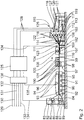
- a corrugated cardboard machine like the one in the Fig. 1 and 2 is shown schematically, comprises a first corrugated cardboard production device 1 for producing a one-sided laminated, endless first corrugated cardboard web 2 and a second corrugated cardboard production device 3 for producing a single-sided laminated, endless second corrugated cardboard web 4.
- a first splice device 5 and a second splice device 6 are assigned to the first corrugated cardboard production device 1, while a third splice device 7 and a fourth splice device 8 are assigned to the second corrugated cardboard production device 3.
- the first splice device 5 comprises a first unwinding unit 10 for unrolling a finite first material web from a first material web reel 9 and a second unwinding unit for unrolling a finite second material web from a second material web reel 11 Roll-off unit 12.
- the finite first and second material web are connected to one another by means of a connecting and cutting unit (not shown) of the first splice device 5 in order to provide an endless first material web 13.
- a connecting and cutting unit (not shown) of the first splice device 5 in order to provide an endless first material web 13.
- the second splice device 6 is designed corresponding to the first splice device 5. This has a third unwind unit 15 for unrolling a finite third material web from a third material web roll 14 and a fourth unwind unit 17 for unrolling a finite fourth material web from a fourth material web roll 16.
- the finite third and fourth material web are connected to one another to provide an endless second material web 18 by means of a connecting and cutting unit (not shown) of the second splice device 6.
- a connecting and cutting unit not shown
- the endless first material web 13 is preferably fed via at least one first deflection roller 19 to a first preheating device 20, which comprises a first, heatable preheating roller 21.
- the end of the endless first material web 13 lies on the outside with one side against the first preheating roller 21.
- the preheated endless first material web 13 is then preferably fed to the first corrugated cardboard production device 1 via at least one second deflection roller 22.
- the endless second material web 18 is preferably fed to the first corrugated cardboard production device 1 via at least one third deflection roller 23.
- the third splice device 7 is designed in accordance with the first splice device 5. This comprises a fifth unwind unit 25 for unrolling a finite fifth material web from a fifth material web roll 24 and a sixth unwind unit 27 for unrolling a finite sixth material web from a sixth material web roll 26.
- the finite fifth and sixth material web are connected to one another by means of a connecting and cutting unit (not shown) of the third splice device 7 in order to provide an endless third material web 28.
- a third connecting seam is formed in the endless third material web 28.
- the fourth splice device 8 is essentially designed in accordance with the second splice device 6. This comprises a seventh unwind unit 30 for unrolling a finite seventh material web from a seventh material web roll 29 and an eighth for unrolling a finite eighth material web from an eighth material web roll 31 Unrolling unit 32.
- the finite seventh and eighth material web are connected to one another by means of a connecting and cutting unit (not shown) of the fourth splice device 8 to provide an endless fourth material web 33.
- a connecting and cutting unit (not shown) of the fourth splice device 8 to provide an endless fourth material web 33.
- a fourth connecting seam is formed in the endless fourth material web 33.
- the endless third material web 28 is preferably fed via at least a fourth deflection roller 34 to a second preheating device 35 which comprises a second heatable preheating roller 36.
- a second preheating device 35 which comprises a second heatable preheating roller 36.
- One end of the endless third material web 28 lies on the outside of the second preheating roller 36 and is thus heated from this side.
- the heated endless third material web 28 is then preferably fed to the second corrugated cardboard production device 3 via at least one fifth deflection roller 37.
- the first preheating device 20 and the second preheating device 35 can be temperature-controlled or heated independently of one another.
- the preheating temperature of the preheating rollers 21, 36 can be changed.
- the endless fourth material web 33 is preferably fed to the second corrugated cardboard production device 3 via at least a sixth deflection roller 38.
- the first corrugated cardboard production device 1 comprises, for producing an endless corrugated web 39 having a corrugation from the endless second material web 18, a first corrugated roller 41 rotatably mounted about a first axis of rotation 40 and a second Axle 42 rotatably mounted second corrugated roller 43.
- the corrugated rollers 41, 43 form the Passing and corrugating the endless second material web 18 out of a roll gap, the axes of rotation 40, 42 running parallel to one another.
- the corrugated rollers 41, 43 together form a first corrugated device.
- the first corrugated cardboard production device 1 has a first glue application device 44, which in turn is a first glue -Dosing roller 45, a first glue container (not shown) and a first glue application roller 46 comprises.
- the first glue application roller 46 forms a glue gap with the first corrugating roller 41, the first glue application roller 46 being partially arranged within the first glue container immersed in it. The glue from the glue container is applied to tips of the corrugation of the first corrugated web 39.
- the first glue metering roller 45 bears against the first glue application roller 46 and serves to form a uniform layer of glue on the first glue application roller 46.
- the first glue application roller 46 is opposite the first Ripple roller 41 adjustable so that the glue gap present between them can be changed. A change in the glue gap leads to a change in the amount of glue transferred from the first glue container to the first corrugated web 39.
- the endless first material web 13 is then joined together with the glued first corrugated web 39 in the first corrugated cardboard production device 1.
- the first corrugated cardboard production device 1 has a first press belt module 47 for pressing the endless first material web 13 against the glue-provided first corrugated web 39, which in turn abuts the first corrugated roller 41 in some areas
- the first pressure belt module 47 is arranged above the first corrugated roller 41. It has a first pressure roller 49 which is rotatably mounted about a third axis of rotation 48 and a second pressure roller 51 which is rotatably mounted about a fourth axis of rotation 50, and an endless pressure belt 52 which runs around the pressure rollers 49, 51 is led around.
- the first corrugated roller 41 engages in a space between the pressure rollers 49, 51 in some areas from below.
- the pressure belt 52 is deflected by the first corrugated roller 41. It presses against the endless first material web 13, which in turn is pressed against the first corrugated web 39 provided with glue and abutting the first corrugating roller 41.
- first storage device 53 For the intermediate storage and buffering of the one-sided laminated first corrugated web 2, it is fed to a first storage device 53, where it has loops.
- the second corrugated cardboard production device 3 is identical to the first corrugated cardboard production device 1.
- the second corrugated cardboard production device 3 comprises, for producing an endless second corrugated web 54 having a corrugation from the endless fourth material web 33, a third corrugated roller 56 rotatably mounted about a fifth axis of rotation 55 and a sixth rotation -Axis 57 rotatably mounted fourth corrugated roller 58.
- the third corrugated roller 56 and the fourth corrugated roller 58 form for the passage and corrugation of the endless fourth Material web 33 from a roll gap, the fifth axis of rotation 55 and the sixth axis of rotation 57 being parallel to one another.
- the third corrugated roller 56 and the fourth corrugated roller 58 together form a corrugated device.
- the second corrugated board production device 3 has a second glue application device 59, which in turn is a second Glue metering roller 60, a second glue container (not shown) and a second glue application roller 61 comprises.
- the second glue application roller 61 forms a glue gap with the third corrugating roller 56, the second glue application roller 61 being arranged partially inside the second glue container immersed in it. The glue from the second glue container is applied to tips of the corrugation of the second corrugated sheet 54.
- the second glue metering roller 60 bears against the second glue application roller 61 and serves to form a uniform layer of glue on the second glue application roller 61.
- the second glue application roller 61 is opposite the third Ripple roller 56 adjustable so that the glue gap between them can be changed. A change in the glue gap leads to a change in the amount of glue transferred from the second glue container to the second corrugated web 54.
- the endless third material web 28 is then joined together with the second corrugated web 54 provided with glue from the second glue container in the second corrugated cardboard production device 3.
- the second corrugated cardboard production device 3 has a second press belt module 62
- the second pressure belt module 62 is arranged above the third corrugated roller 56. It has a third pressure roller 64 which is rotatably mounted about a seventh axis of rotation 63 and a fourth pressure roller 66 which is rotatably mounted about an eighth axis of rotation 65 and a second pressure belt 67 which rotates about the third pressure roller 64 and the fourth pressure roller 66 is guided around.
- the third corrugated roller 56 engages in areas from below in a space present between the third pressure roller 64 and the fourth pressure roller 66.
- the second pressure belt 67 is deflected by the third corrugated roller 56. It presses against the endless third material web 28, which in turn is pressed against the second corrugated web 54 provided with glue and abutting the third corrugating roller 56.
- a preheating arrangement 69 which comprises a third, fourth and fifth preheating device 70, 71 and 72, respectively.
- the third, fourth and fifth preheating devices 70, 71 and 72 are arranged one above the other.
- the fourth preheating device 71 is arranged between the preheating devices 70, 72.
- the third preheating device 70 has a third heatable preheating roller 73, while the fourth preheating device 71 has a fourth heatable preheating roller 74.
- the fifth preheating device 72 has a fifth heatable preheating roller 75.
- the preheating rollers 73, 74, 75 can be temperature-controlled or heated independently of one another. The preheating temperature of the preheating rollers 73, 74, 75 can therefore be changed.
- the first corrugated cardboard web 2 is fed to the third preheating device 70 and abuts one side on the third preheating roller 73.
- the second corrugated cardboard web 4 is fed to the fourth preheating device 71 and abuts one side on the fourth preheating roller 74.
- An endless cover web 76 is fed to the fifth preheating device 72 and rests with one side in regions on the fifth preheating roller 75.
- a fifth splice device 77 comprises a ninth unwinding unit 79 for unrolling a finite ninth material web from a ninth material web roll 78 and a tenth for unrolling a finite tenth material web from a tenth material web roll 80 Unwind unit 81.
- the finite ninth material web and tenth material web are connected to one another by means of a connecting and cutting unit (not shown) of the fifth splice device 77 in order to provide the endless cover web 76.
- a connecting and cutting unit (not shown) of the fifth splice device 77 in order to provide the endless cover web 76.
- a glue unit 82 which comprises a first gluing device 83 and a second gluing device 84, is located downstream of the preheating arrangement 69 Fig. 2 is shown.
- the first gluing device 83 has a first gluing roller 85 which dips into a first glue bath 86 and transfers glue from the first glue bath 86 onto the preheated first corrugated cardboard web 2.
- the first gluing roller 85 is adjustable in such a way that the amount of glue transferred or transferable to the first corrugated cardboard web 2 can be changed.
- the second gluing device 84 has a second gluing roller 87 which dips into a second glue bath 88 and transfers glue from the second glue bath 88 to the preheated second corrugated cardboard web 4.
- the second gluing roller 87 is adjustable in such a way that the amount of glue transferred or transferable to the second corrugated cardboard web 4 can be changed.
- the first gluing roller 85 and the second gluing roller 87 are adjustable independently of one another.
- the cover sheet 76 is guided in the glue plant 82 via a seventh deflection roller 89.
- the second gluing device 84 is arranged between the first gluing device 83 and the seventh deflection roller 89.
- a heating and pressing device 90 is arranged downstream of the glue unit 82.
- the heating-pressing device 90 comprises a horizontally extending table 91 with heating elements 92. The heating temperature of the heating elements 92 can be changed. Above the table 91, the heating-pressing device 90 has a driven, endless pressing belt 94 which is deflected via rollers 93 and is driven by the pressing belt 94.
- the first corrugated cardboard web 2 can be sprayed with steam.
- a pressure gap 95 is formed between the pressure belt 94 and the table 91, through which the glued first corrugated cardboard web 2, the glued second corrugated cardboard web 4 and the cover web 76 are guided and pressed against one another there.
- the Heating elements 92 are arranged adjacent to the cover sheet 76, while the pressure belt 94 is arranged adjacent to the first corrugated sheet 2.
- a five-ply endless corrugated cardboard web 96 is formed in the heating and pressing device 90.
- the corrugated cardboard system Downstream of the heating and pressing device 90, the corrugated cardboard system has a longitudinal cutting-creasing device 97.
- the longitudinal cutting-creasing device 97 comprises on the input side two creasing stations 98 arranged one behind the other and two longitudinal cutting creases arranged one behind the other. Stations 99.
- the creasing stations 98 each have paired creasing tools 100, between which the five-ply corrugated cardboard web 96 is carried out.
- the longitudinal cutting stations 99 each have knives 101 which can be driven in rotation and which can be brought into engagement with the five-layer corrugated cardboard web 96 for the longitudinal severing thereof.
- the knives 101 interact with oppositely arranged, rotationally driven brush rollers, not shown, when the knives 101 are immersed in the five-layer corrugated cardboard web 96.
- the as yet undivided five-ply corrugated cardboard web 96 can be divided into a plurality of endless partial corrugated cardboard webs 110, which are conveyed in a transport direction 105 and are initially adjacent to one another.
- a short-transverse cutting device 102 is arranged downstream of the longitudinal cutting-creasing device 97.
- the short-transverse cutting device 102 has a housing 103 in which a roller 104 extends around a direction perpendicular to the transport direction 105 of the corrugated cardboard web 96 Rotation axis 106 is mounted.
- the housing 103 of the short cross-cutting device 102 is designed in such a way that the five-ply corrugated cardboard web 96 can be transported beneath the rotationally driven roller 104 by the short cross-cutting device 102.
- a radially outwardly extending knife 107 is arranged, which extends perpendicular to the transport direction 105 over the entire width of the five-ply corrugated cardboard web 96.
- Each support device 108 comprises a cutting support 109, also referred to as an anvil, which is attached to a piston rod of a hydraulic cylinder (not shown).
- the piston rod is displaceable in a housing of the hydraulic cylinder in the transport direction 105.
- the housing of the hydraulic cylinder is fastened at its end facing away from the piston rod to the housing 103 of the short-transverse cutting device 102.
- Each cutting support 109 can be moved into a first and second position by means of the associated hydraulic cylinder.
- the cutting support 109 In the first position, which is the cutting position, the cutting support 109 is located directly below the roller 104. The vertical distance between the roller 104 and the cutting support 109 is selected such that the knife 107 rotates when the roller rotates 104 about the axis of rotation 106 does not just touch the cutting support 109.
- the piston rod of the hydraulic cylinder In the second position, which is the non-cutting position, the piston rod of the hydraulic cylinder is fully extended, so that the cutting support 109 is in front of the roller 104 in the transport direction 105.
- the short-transverse cutting device 102 serves on the one hand for the safe removal of start-up waste and on the other hand carries out job or format changes.
- connection cuts running perpendicularly or obliquely to the transport direction 105 can be produced, which connect the respective longitudinal cuts produced by the longitudinal cutting stations 99, so that the partial corrugated cardboard webs 110 preferably remain endless.
- Unit 113 Downstream of the short cross-cutting device 102 there is a switch 111 which has a feed table 112 for transporting the partial corrugated webs 110 and a discharge table for removing the partial corrugated webs 110 in three levels.
- Unit 113 comprises three discharge tables 114.
- switch elements For better transfer of the partial corrugated cardboard webs 110 from the feed table 112 to the discharge tables 114, there are preferably a plurality of switch elements which are arranged next to one another on the feed table 112 and are pivotable transversely to the transport direction 105 and are relative to the discharge tables 114 can be pivoted into corresponding angular positions.
- Another number of discharge table units 113 is alternatively possible.
- a cross-cutting device 115 Downstream of the switch 111, a cross-cutting device 115 is provided, which has three partial cross-cutting devices 116 arranged one above the other.
- Each partial cross-cutting device 116 comprises two cross-cutting rollers 117 which can be driven in rotation, arranged in pairs one above the other and extending transversely to the transport direction 105.
- Each cross-cutting roller 117 has a radially outwardly extending cross-cutting edge Knife 118 for the complete cross-cutting of the partial corrugated cardboard webs 110 and thus for the production of corrugated cardboard sheets 119.
- the cross-cutting knives 118 of each partial-cross-cutting device 116 act to cross-cut the partial Corrugated sheets 110 together and are driven accordingly.
- a conveyor belt 120 is arranged downstream of each partial cross-cutting device 116 in order to feed the cut-to-size corrugated cardboard sheets 119 to stack-depositing devices 121.
- a stack-depositing device 121 is assigned to each conveyor belt 120.
- the corrugated cardboard system also includes a curvature detection device 122 for detecting the curvature of the partial corrugated cardboard sheets 110 and the corrugated cardboard sheets 119.
- the curvature detection device 122 in turn has a first curvature detection device 123, which is arranged upstream of the cross-cutting device 115 and extends transversely to the transport direction 105 over the entire width of the partial corrugated cardboard webs 110 extends. When viewed in more detail, it is arranged between the longitudinal cutting-creasing device 97 and the cross-cutting device 115. In more detail, this is arranged between the short cross-cutting device 102 and the cross-cutting device 115. In more detail, the first curvature detection device 123 is arranged between the short-transverse cutting device 102 and the switch 111. It is preferably immovable at least in the transport direction 105.
- the first curvature detection device 123 is able to detect the curvature of the partial corrugated cardboard webs 110.
- it includes, for example, a first curvature detection sensor, which is arranged above or below the partial corrugated sheets 110.
- two curvature detection sensors are provided, which are arranged opposite one another. The partial corrugated cardboard webs 110 then run between them.
- the first curvature detection device 123 is in particular capable of curving the partial corrugated cardboard webs 110 in the transport direction 105 and / or transversely thereto upwards and / or downwards with respect to a plane or extending them in one plane to detect.
- the first curvature detection device 123 is in signal connection with an information processing device 125 via a first signal line 124. Via the first signal line 124, the information processing device 125 is supplied with curvature information relating to the individual partial corrugated cardboard webs 110.
- the curvature detection device 122 has a second curvature detection device 126, which is arranged downstream of the cross-cutting device 115. In more detail, this is arranged between the cross-cutting device 115 and the stack-depositing devices 121.
- the second curvature detection device 126 in turn has three second curvature detection units 127.
- a curvature detection unit 127 is assigned to each conveyor belt 120.
- Each curvature detection unit 127 can comprise a curvature detection sensor which is arranged above or below the respective conveyor belt 120 and is preferably immobile at least in the direction of its conveyance.
- each curvature detection unit 127 has two curvature detection sensors, which are arranged in pairs above and below the respective conveyor belt 120 and detect the curvature of the sheets of corrugated cardboard 119 conveyed thereon.
- the curvature detection units 127 are able to detect the curvature of the corrugated cardboard sheets 119 in their respective transport directions and / or transversely to them upwards and / or downwards with respect to a respective plane or their extension in one plane.
- Each curvature detection unit 127 is in signal connection with the information processing device 125 via a second signal line 128. Curve information can be fed to the corrugated cardboard sheets 119 of the information processing device 125 via the second signal lines 128.
- the information processing device 125 is in particular able to set values for the corrugated cardboard webs 2, 4, 96 or for the partial corrugated cardboard webs 110, in particular the preheating temperature of the first preheating roller 21, the preheating Temperature of the second preheating roller 36, the preheating temperature of the third preheating roller 73, the preheating temperature of the fourth preheating roller 74, the preheating temperature of the fifth preheating roller 75, the heating temperature of the heating elements 92 to change or correct the steam supply through the pressure belt 94, the glue gap in the first corrugated cardboard production device 1 and / or the glue gap in the second corrugated cardboard production device 3.
- the information processing device 125 has a signal connection to the first preheating device 20 via a third signal line 129 in order to change the preheating temperature of its preheating roller 21, if necessary in order to influence the curvature of the corrugated cardboard sheets 119 ,
- the information processing device 125 is in a signal connection via a fourth signal line 130 to the first glue application device 44 of the first corrugated cardboard production device 1 in order to adjust the glue application roller 46 thereof and so on change the glue application, in particular the amount of glue application, in order to influence the curvature of the corrugated cardboard sheets 119.
- the information processing device 125 is in signal connection with the second preheating device 35 via a fifth signal line 131 in order to change the preheating temperature of its preheating roller 36, if necessary, in order to influence the curvature of the corrugated cardboard sheets 119.
- the information processing device 125 is in signal connection via a sixth signal line 132 to the second glue application device 59 of the second corrugated cardboard production device 3 in order to adjust the glue application roller 61 thereof and so on change the glue application, in particular the amount of glue application, in order to influence the curvature of the corrugated cardboard sheets 119.
- the information processing device 125 is also connected via a seventh signal line 133 to the third preheating device 70, the fourth preheating device 71 and the fourth preheating device 72 in order to determine the preheating temperatures of their preheating -Rolls 73, 74 and 75 independently of one another, if necessary, in order to influence the curvature of the corrugated cardboard sheets 119.
- the information processing device 125 is connected to the first gluing device 83 and the second via an eighth signal line 134 Glueing device 84 in signal connection, in order to change the position of its gluing rollers 85 and 87, respectively, and thus the gluing of the first and second corrugated cardboard webs 2, 4, in order to influence the curvature of the corrugated cardboard sheets 119 ,
- the information processing device 125 is in signal connection with the heating-pressing device 90 via a ninth signal line 135, in order, if necessary, to determine the heating temperature of its heating elements 92 and / or the steam supply through the pressing - Change strap 94 to affect the curvature of corrugated sheets 119.
- At least one of the corrugated cardboard sheet curvature influencing devices 20, 35, 44, 59, 69, 82, 90 is actuated accordingly via the respective signal line 124, 128 to 135.
- the information processing device 125 stores a curvature of the partial corrugated cardboard webs 110 or curvature information detected by the first curvature detection device 123 and also a curvature of the corrugated cardboard detected by the second curvature detection device 126 Sheets 119 or curvature information for these, if the information processing device 125 detects a deviation of the curvature of the corrugated cardboard sheets 119 in the second curvature detection device 126 from a desired curvature of the corrugated cardboard sheets 119.
- the information processing device 125 interrupts when the curvature of the partial corrugated cardboard webs 110 on the first curvature detection device 123 is interrupted by at least one of the corrugated cardboard sheet curvature influencing devices 20, 35, 44, 59, 69, 82, 90 regulate the curvature of the corrugated cardboard sheets 119.
- the information processing device 125 compares the actual curvature of the corrugated cardboard sheets 119 at the second curvature detection device 126 with the desired curvature of the corrugated cardboard sheets 119. The information processing device 125 repeats this until that The actual curvature of the corrugated cardboard sheets 119 corresponds to the target curvature of the corrugated cardboard sheets 119.
- the information processing device 125 immediately causes a change in the curvature of the corrugated cardboard sheets 119 by at least one of the corrugated cardboard sheet curvature Influencing devices 20, 35, 44, 59, 69, 82, 90.
- the information processing device 125 stores the curvature tendency from the first curvature detection device 123 to the second curvature detection device 126 in order to shorten the controlled system to the first curvature detection device 123.
- the information processing device 125 comprises a programmable logic controller 136 which controls the heating, preheating temperatures or the glue application.
- the information processing device 125 comprises a user interface.
- the user interface allows one Intervention in the regulation of the corrugated cardboard system or the curvature of the corrugated cardboard sheets 119.
Landscapes
- Engineering & Computer Science (AREA)
- Mechanical Engineering (AREA)
- Machines For Manufacturing Corrugated Board In Mechanical Paper-Making Processes (AREA)
- Making Paper Articles (AREA)
Description
- Auf den Inhalt der deutschen Patentanmeldung
DE 10 2014 202 537.0 wird wollumfänglich Bezug genommen. - Die Erfindung betrifft eine Wellpappe-Anlage zur Herstellung von Wellpappe-Bögen gemäß dem Oberbegriff des Anspruchs 1. Ferner richtet sich die Erfindung auf ein Verfahren zur Herstellung von Wellpappe-Bögen in einer Wellpappe-Anlage.
- Wellpappe-Anlagen zur Herstellung von Wellpappe-Bögen sind aus dem Stand der Technik durch offenkundige Vorbenutzung allgemein bekannt. Die Wellpappe-Bögen werden aus endlosen Wellpappe-Bahnen oder aus Teil-Wellpappe-Bahnen erzeugt, die wiederum aus den endlosen Wellpappe-Bahnen stammen. Ein weit verbreitetes Problem bei der Herstellung von Wellpappe-Bögen ist, dass sich die Wellpappe-Bögen nach deren Erzeugung krümmen bzw. wölben. Dies ist im Allgemeinen auf eine fehlerhafte Einstellung der Wellpappe-Anlage, Defekte an der Wellpappe-Anlage und/oder mangelhafte Rohstoffe, wie des Rohpapiers, zurückzuführen. Derartige gekrümmte Wellpappe-Bögen können oftmals nicht weiterverwendet werden.
- Aus der
US 2005/284579 A1 sind gattungsgemäße Wellpappe-Anlagen bekannt. DieEP 1 902 883 A1 ,EP 2 503 421 A1 undUS 3,004,880 offenbaren weitere Wellpappe-Anlagen. - Der Erfindung liegt daher die Aufgabe zugrunde, eine Wellpappe-Anlage zur Herstellung von Wellpappe-Bögen zu schaffen, die die oben angegebenen Nachteile überwindet. Insbesondere soll eine Wellpappe-Anlage zur Herstellung von Wellpappe-Bögen bereitgestellt werden, die eine gewünschte Krümmung (Soll-Krümmung) haben oder plan sind. Ferner sollen Abweichungen von der gewünschten Krümmung bzw. der gewünschten Erstreckung der Wellpappe-Bögen möglichst frühzeitig bei deren Herstellung erkennbar sein. Ein entsprechendes Verfahren zum Herstellen von Wellpappe-Bögen soll ebenfalls geschaffen werden.
- Diese Aufgabe wird erfindungsgemäß durch die in den unabhängigen Ansprüchen 1 und 15 angegebenen Merkmale gelöst. Der Kern der Erfindung liegt darin, dass eine Krümmungs-Detektions-Vorrichtung eine Krümmung von Wellpappe-Bögen und/oder von Teil-Wellpappe-Bahnen detektiert. Die Krümmung der Wellpappe-Bögen ist durch mindestens eine Wellpappe-Bogen-Krümmungs-Beeinflussungs-Einrichtung in Abhängigkeit von Krümmungs-Informationen zu den Wellpappe-Bögen und/oder Teil-Wellpappe-Bahnen beeinflussbar, insbesondere regelbar, so dass die Wellpappe-Bögen eine gewünschte Krümmung bzw. einen gewünschten Verlauf über deren Länge und/oder Breite haben.
- Die Informations-Verarbeitungs-Einrichtung führt zu einer äußerst schnellen Reaktions-Zeit, so dass die Anzahl mangelhafter Wellpappe-Bögen auf ein Minimum reduzierbar ist.
- Die erste Material-Vorrats-Vorrichtung ist vorzugsweise als Splice-Vorrichtung ausgeführt.
- Es ist von Vorteil, wenn auch die zweite Material-Vorrats-Vorrichtung als Splice-Vorrichtung ausgebildet ist.
- Günstigerweise umfasst die Quer-Schneide-Vorrichtung mindestens eine Messer-Walze mit mindestens einem Messer zum Quer-Schneiden mindestens der mindestens einseitig kaschierten ersten Wellpappe-Bahn.
- Vorzugsweise wird eine endlose Wellpappe-Bahn, die die erste Wellpappe-Bahn ist oder umfasst, in verschiedene Teil-Wellpappe-Bahnen geschnitten und aufgeteilt. Es ist von Vorteil, wenn jeder Teil-Wellpappe-Bahn mindestens eine Messer-Walze mit mindestens einem Messer zum Quer-Schneiden der jeweiligen Teil-Wellpappe-Bahn zugeordnet ist. Es ist von Vorteil, wenn eine Längs-Schneide-Rill-Einrichtung die Teil-Wellpappe-Bahnen aus mindestens der ersten und zweiten Material-Bahn erzeugt.
- Die Krümmungs-Detektions-Vorrichtung ist insbesondere imstande zu detektieren, ob die Wellpappe-Bögen und/oder die Teil-Wellpappe-Bahnen über deren Länge und/oder Breite zumindest bereichsweise gekrümmt oder ungekrümmt sind.
- Günstigerweise arbeitet die Krümmungs-Detektions-Vorrichtung berührungslos. Die Krümmungs-Detektions-Vorrichtung detektiert beispielsweise die jeweils vorherrschende Distanz zu dem jeweiligen Wellpappe-Bogen bzw. zu der jeweiligen Teil-Wellpappe-Bahn über dessen/deren gesamte Breite und/oder Länge. Alternativ detektiert die Krümmungs-Detektions-Vorrichtung vorzugsweise das Profil des gesamten jeweiligen Wellpappe-Bogens bzw. der gesamten jeweiligen Teil-Wellpappe-Bahn. Besonders bevorzugt ist die Krümmungs-Detektions-Vorrichtung als Laser-Distanz-Detektions-Vorrichtung oder als Linien-Profil-Detektions-Vorrichtung ausgeführt.
- Es ist zweckmäßig, wenn die Krümmungs-Detektions-Vorrichtung zumindest in einer Transport-Richtung der Wellpappe-Bahn bzw. der Wellpappe-Bögen unbeweglich ist.
- Es ist von Vorteil, wenn die Informations-Verarbeitungs-Einrichtung eine elektronische Informations-Verarbeitungs-Einrichtung ist.
- Vorzugsweise sind mehrere Wellpappe-Bogen-Krümmungs-Beeinflussungs-Einrichtungen vorhanden. Es ist von Vorteil, wenn die Informations-Verarbeitungs-Einrichtung Betätigungs-Signale zu mindestens einer der Wellpappe-Bogen-Krümmungs-Beeinflussungs-Einrichtungen schickt, um die Krümmung der Wellpappe-Bögen zu beeinflussen.
- Es ist von Vorteil, wenn mindestens eine, vorzugsweise mehrere, bevorzugter alle, der Wellpappe-Bogen-Krümmungs-Beeinflussungs-Einrichtungen bei einer erforderlichen Beeinflussung der Krümmung der Wellpappe-Bögen die Krümmung der Wellpappe-Bögen in deren Transport-Richtung und/oder quer zu deren Transport-Richtung beeinflussen.
- Die Krümmung der Wellpappe-Bögen ist beispielsweise durch einseitige Veränderung der Feuchte und/oder Temperatur von mindestens einer Material-Bahn bzw. von mindestens einer Wellpappe-Bahn beeinflussbar.
- Es ist zweckmäßig, wenn die Informations-Verarbeitungs-Einrichtung und die mindestens eine Wellpappe-Bogen-Krümmungs-Beeinflussungs-Einrichtung miteinander in drahtloser oder drahtgebundener Signal-Verbindung stehen.
- Günstigerweise steht die Krümmungs-Detektions-Vorrichtung und die Informations-Verarbeitungs-Einrichtung miteinander in drahtloser oder drahtgebundener Signal-Verbindung.
- Weitere vorteilhafte Ausgestaltungen der Erfindung sind in den Unteransprüchen angegeben.
- Es ist von Vorteil, wenn die in dem Unteranspruch 2 angegebene erste Vorheiz-Einrichtung eine erste Vorheiz-Walze umfasst, an der die erste Material-Bahn bereichsweise anliegt. Die erste Material-Bahn wird so von ihrer an der ersten Vorheiz-Walze anliegenden Seite aus zumindest bereichsweise über deren Dicke vorgeheizt. Die Vorheiz-Temperatur der ersten Vorheiz-Walze ist veränderbar, was zu einer Veränderung der Krümmung der Wellpappe-Bögen führt. Eine Erhöhung dieser Vorheiz-Temperatur bewirkt eine Krümmung der Wellpappe-Bögen nach unten, also einen Down Warp.
- Durch die in dem Unteranspruch 3 angegebene Leim-Auftrags-Einrichtung ist die Beleimung der ersten und/oder zweiten Material-Bahn veränderbar, was zu einer Veränderung der Krümmung der Wellpappe-Bögen führt. Insbesondere ist die Leim-Auftrags-Menge veränderbar. Alternativ ist die Zusammensetzung, insbesondere die Feuchte des Leims veränderbar. Es ist von Vorteil, wenn die Leim-Auftrags-Einrichtung eine Leim-Auftrags-Walze umfasst, die Leim auf die an ihr anliegenden Seite der jeweiligen Material-Bahn aufträgt. Durch Verstellung der Leim-Auftrags-Walze gegenüber dieser Material-Bahn ist beispielsweise die Menge des Leim-Auftrags auf diese Material-Bahn einfach veränderbar, was wiederum einen Einfluss auf die in dieser Material-Bahn vorliegende Feuchte hat. Eine Erhöhung der in der zweiten Material-Bahn vorliegenden Feuchte bewirkt eine Krümmung der Wellpappe-Bögen nach oben, also einen Up Warp.
- Die in dem Unteranspruch 4 angegebene dritte Material-Vorrats-Vorrichtung ist vorzugsweise als Splice-Vorrichtung ausgeführt.
- Es ist von Vorteil, wenn die vierte Material-Vorrats-Vorrichtung als Splice-Vorrichtung ausgebildet ist.
- Die erste Wellpappe-Bahn und die zweite Wellpappe-Bahn sind vorzugsweise lagenartig miteinander verbindbar, bevorzugter miteinander verleimbar. Vorzugsweise ist eine weitere Deck-Bahn mit einer freien Well-Bahn der ersten oder zweiten Wellpappe-Bahn verbindbar, bevorzugter verleimbar.
- Es ist von Vorteil, wenn die in dem Unteranspruch 5 angegebene zweite Vorheiz-Einrichtung eine zweite Vorheiz-Walze umfasst, an der die dritte Material-Bahn bereichsweise anliegt. Die dritte Material-Bahn wird so von ihrer an der zweiten Vorheiz-Walze anliegenden Seite aus zumindest bereichsweise über deren Dicke vorgeheizt. Die Vorheiz-Temperatur der zweiten Vorheiz-Walze ist veränderbar, was zu einer Veränderung der Krümmung der Wellpappe-Bögen führt. Eine Erhöhung dieser Vorheiz-Temperatur bewirkt eine Krümmung der Wellpappe-Bögen nach unten, also einen Down Warp.
- Durch die in dem Unteranspruch 6 angegebene Leim-Auftrags-Einrichtung ist die Beleimung dritten und/oder vierten Material-Bahn veränderbar, was zu einer Veränderung der Krümmung der Wellpappe-Bögen führt. Insbesondere ist die Leim-Auftrags-Menge veränderbar. Alternativ ist die Zusammensetzung, insbesondere die Feuchte, des Leims veränderbar. Es ist von Vorteil, wenn die Leim-Auftrags-Einrichtung eine Leim-Auftrags-Walze umfasst, die Leim auf die an ihr anliegenden Seite der jeweiligen Material-Bahn aufträgt. Durch Verstellung der Leim-Auftrags-Walze gegenüber dieser Material-Bahn ist beispielsweise die Menge des Leim-Auftrags auf diese Material-Bahn einfach veränderbar, was wiederum einen Einfluss auf die in der Material-Bahn vorliegende Feuchte hat. Eine Erhöhung der in der vierten Material-Bahn vorliegenden Feuchte bewirkt eine Krümmung der Wellpappe-Bögen nach oben, also einen Up Warp.
- Vorzugsweise hat die Vorheiz-Anordnung gemäß dem Unteranspruch 7 eine der ersten Wellpappe-Bahn zugeordnete Vorheiz-Walze, an der die erste Wellpappe-Bahn bereichsweise außen anliegt und so von ihrer anliegenden Seite aus vorgeheizt wird.
- Günstigerweise hat die Vorheiz-Anordnung eine der zweiten Wellpappe-Bahn zugeordnete weitere Vorheiz-Walze, an der die zweite Wellpappe-Bahn bereichsweise außen anliegt und so von ihrer anliegenden Seite aus vorgeheizt wird.
- Es ist zweckmäßig, wenn die Vorheiz-Anordnung eine einer Deck-Bahn zugeordnete weitere Vorheiz-Walze umfasst, an der die Deck-Bahn bereichsweise außen anliegt und so von ihrer anliegenden Seite aus vorgeheizt wird.
- Die Vorheiz-Temperatur der Vorheiz-Anordnung bei der ersten Wellpappe-Bahn, der zweiten Wellpappe-Bahn und/oder der Deck-Bahn ist veränderbar, was zu einer Veränderung der Krümmung der Wellpappe-Bögen führt. Bevorzugt ist die Vorheiz-Temperatur mindestens einer, bevorzugter sämtlicher, der Vorheiz-Walzen der Vorheiz-Anordnung veränderbar, was zu einer Veränderung der Krümmung der Wellpappe-Bögen führt. Eine Erhöhung der Vorheiz-Temperatur bei der ersten Wellpappe-Bahn bewirkt eine Krümmung der Wellpappe-Bögen nach unten, also einen Down Warp. Eine Erhöhung der Vorheiz-Temperatur bei der zweiten Wellpappe-Bahn bewirkt eine Krümmung der Wellpappe-Bögen nach unten, also einen Down Warp. Eine Erhöhung der Vorheiz-Temperatur bei der Deck-Bahn bewirkt eine Krümmung der Wellpappe-Bögen nach oben, also einen Up Warp.
- Vorzugsweise hat das Leim-Werk gemäß dem Unteranspruch 8 eine der ersten Wellpappe-Bahn zugeordnete erste Beleimungs-Einrichtung zur Beleimung der ersten Wellpappe-Bahn.
- Günstigerweise hat das Leim-Werk eine der zweiten Wellpappe-Bahn zugeordnete zweite Beleimungs-Einrichtung zur Beleimungs-Einrichtung zur Beleimung der zweiten Wellpappe-Bahn.
- Die Beleimung der ersten Wellpappe-Bahn und/oder zweiten Wellpappe-Bahn ist veränderbar, was zu einer Veränderung der Krümmung der Wellpappe-Bögen führt. Insbesondere ist die Leim-Auftrags-Menge veränderbar. Alternativ ist die Zusammensetzung, insbesondere die Feuchte, des Leims veränderbar. Es ist von Vorteil, wenn die erste Beleimungs-Einrichtung eine erste Beleimungs-Walze umfasst, die Leim auf die an ihr anliegenden Seite der jeweiligen Wellpappe-Bahn aufträgt. Günstigerweise hat die zweite Beleimungs-Einrichtung eine zweite Beleimungs-Walze, die Leim auf die an ihr anliegenden Seite der jeweiligen Wellpappe-Bahn aufträgt. Durch Verstellung der ersten und/oder Beleimungs-Walze gegenüber der zugehörigen Wellpappe-Bahn ist beispielsweise die Menge des Leim-Auftrags auf diese Wellpappe-Bahn einfach veränderbar, was wiederum einen Einfluss auf die in der Wellpappe-Bahn vorliegende Feuchte hat. Eine Erhöhung der in der ersten Wellpappe-Bahn vorliegenden Feuchte bewirkt eine Krümmung der Wellpappe-Bögen nach oben, also einen Up Warp. Eine Erhöhung der in der zweiten Wellpappe-Bahn vorliegenden Feuchte bewirkt eine Krümmung der Wellpappe-Bögen nach unten, also einen Down Warp.
- Es ist von Vorteil, wenn die Heiz-Andrück-Einrichtung gemäß dem Unteranspruch 9 mindestens ein Heiz-Element umfasst, dessen Heiz-Temperatur veränderbar ist. Durch das mindestens eine Heiz-Element ist die gesamte Wellpappe-Bahn beheizbar. Eine Änderung der Heiz-Temperatur des mindestens einen Heiz-Elements führt zu einer Veränderung der Krümmung der Wellpappe-Bögen. Das mindestens eine Heiz-Element ist benachbart zu der äußeren Wellpappe-Bahn und/oder der Deck-Bahn angeordnet. Bevorzugt ist es nur benachbart zu der Deck-Bahn angeordnet. Eine Erhöhung der Heiz-Temperatur bei der Deck-Bahn bewirkt eine Krümmung der Wellpappe-Bögen nach oben, also einen Up Warp.
- Vorzugsweise hat die Heiz-Andrück-Einrichtung mindestens ein Andrück-Element, das insbesondere als umlaufender Andrück-Gurt ausgeführt ist und günstigerweise an die erste Wellpappe-Bahn drückend angreift. Durch das mindestens eine Andrück-Element ist vorzugsweise alternativ oder zusätzlich zu der Heiz-Temperatur-Änderung durch das mindestens eine Heiz-Element die Feuchtigkeit in der ersten Wellpappe-Bahn veränderbar, sodass so auch die Krümmung der Wellpappe-Bögen beeinflussbar ist. Eine Erhöhung der Feuchtigkeit in der ersten Wellpappe-Bahn durch das mindestens eine Andrück-Element bewirkt eine Krümmung der Wellpappe-Bögen nach oben, also einen Up-Warp. Es ist von Vorteil, wenn durch das mindestens eine Andrück-Element die erste Wellpappe-Bahn mit Dampf oder Flüssigkeit, vorzugsweise durch Sprühen, benetzbar ist. Es ist zweckmäßig, wenn in dem mindestens einen Andrück-Element, mindestens eine, bevorzugter eine Vielzahl von, Austritts-Öffnung/en ausgebildet ist, durch die Flüssigkeit bzw. Dampf zu der ersten Wellpappe-Bahn transportierbar ist.
- Allgemein gilt, dass eine im Vergleich zu der angegebenen Betätigung umgekehrte Betätigung der Wellpappe-Bogen-Krümmungs-Beeinflussungs-Einrichtungen, wie Reduzierung der Vorheiz-Temperatur oder der in der Bahn vorherrschenden Feuchte, zu einer entsprechenden umgekehrten Krümmung der Wellpappe-Bögen führt.
- Durch das Maß der Betätigung der Wellpappe-Bogen-Krümmungs-Beeinflussungs-Einrichtungen ist das Maß der Krümmung der Wellpappe-Bögen beeinflussbar.
- Durch gleichzeitige Betätigung mehrerer der Wellpappe-Bogen-Krümmungs-Beeinflussungs-Einrichtungen mit gleichartigem Einfluss auf das Krümmungs-Verhalten der Wellpappe-Bögen ist das Maß der Krümmung der Wellpappe-Bögen steigerbar.
- Wenn die Wellpappe-Bögen nach unten gekrümmt sind, also wenn ein Down Warp vorliegt, so sind die quer zu der Transport-Richtung der Wellpappe-Bahn verlaufenden Kanten der Wellpappe-Bögen, die also vorauseilend bzw. nacheilend sind, jeweils im Wesentlichen nach unten gewandt bzw. unterhalb eines zwischen diesen Kanten parallel verlaufenden, zentralen Bereichs des jeweiligen Wellpappe-Bogens angeordnet.
- Wenn die Wellpappe-Bögen nach oben gekrümmt sind, also wenn ein Up Warp vorliegt, so sind die quer zu der Transport-Richtung der Wellpappe-Bahn verlaufenden Kanten der Wellpappe-Bögen, die also vorauseilend bzw. nacheilend sind, jeweils im Wesentlichen nach oben gewandt bzw. oberhalb eines zwischen diesen Kanten parallel verlaufenden, zentralen Bereichs des jeweiligen Wellpappe-Bogens angeordnet.
- Die in dem Unteranspruch 10 und 11 angegebenen Krümmungs-Detektions-Einrichtungen können konstruktiv unterschiedlich oder identisch sein. Sie stehen vorzugsweise jeweils mit der Informations-Verarbeitungs-Einrichtung in Signal-Verbindung. Die Informations-Verarbeitungs-Einrichtung empfängt günstigerweise von der ersten Krümmungs-Detektions-Einrichtung Krümmungs-Informationen zu den Teil-Wellpappe-Bahnen. Die Informations-Verarbeitungs-Einrichtung empfängt günstigerweise von der zweiten Krümmungs-Detektions-Einrichtung Krümmungs-Informationen zu den Wellpappe-Bögen.
- Die Ausgestaltung gemäß dem Unteranspruch 13 führt zu einer äußerst hohen Wellpappe-Bogen-Qualität.
- Die Unteransprüche können auch bevorzugte Weiterbildungen des unabhängigen Anspruchs 15 sein.
- Nachfolgend wird unter Bezugnahme auf die beigefügte Zeichnung eine bevorzugte Ausführungsform der Erfindung beispielhaft beschrieben. Dabei zeigen:
- Fig. 1
- einen ersten Teil einer erfindungsgemäßen Wellpappe-Anlage, und
- Fig. 2
- einen zweiten Teil der in
Fig. 1 dargestellten erfindungsgemäßen Wellpappe-Anlage. - Eine Wellpappe-Anlage, wie sie in den
Fig. 1 und2 schematisch dargestellt ist, umfasst eine erste Wellpappe-Produktions-Vorrichtung 1 zur Herstellung einer einseitig kaschierten, endlosen ersten Wellpappe-Bahn 2 und eine zweite Wellpappe-Produktions-Vorrichtung 3 zur Herstellung einer einseitig kaschierten, endlosen zweiten Wellpappe-Bahn 4. - Der ersten Wellpappe-Produktions-Vorrichtung 1 sind eine erste Splice-Vorrichtung 5 und eine zweite Splice-Vorrichtung 6 zugeordnet, während der zweiten Wellpappe-Produktions-Vorrichtung 3 eine dritte Splice-Vorrichtung 7 und eine vierte Splice-Vorrichtung 8 zugeordnet sind.
- Die erste Splice-Vorrichtung 5 umfasst zum Abrollen einer endlichen ersten Material-Bahn von einer ersten Material-Bahn-Rolle 9 eine erste Abroll-Einheit 10 und zum Abrollen einer endlichen zweiten Material-Bahn von einer zweiten Material-Bahn-Rolle 11 eine zweite Abroll-Einheit 12. Die endliche erste und zweite Material-Bahn werden zum Bereitstellen einer endlosen ersten Material-Bahn 13 mittels einer nicht dargestellten Verbinde- und Schneide-Einheit der ersten Splice-Vorrichtung 5 miteinander verbunden. Bei jedem Verbinden der endlichen ersten und zweiten Material-Bahnen miteinander entsteht in der endlosen ersten Material-Bahn 13 eine erste Verbindungs-Naht.
- Die zweite Splice-Vorrichtung 6 ist entsprechend der ersten Splice-Vorrichtung 5 ausgebildet. Diese hat zum Abrollen einer endlichen dritten Material-Bahn von einer dritten Material-Bahn-Rolle 14 eine dritte Abroll-Einheit 15 und zum Abrollen einer endlichen vierten Material-Bahn von einer vierten Material-Bahn-Rolle 16 eine vierte Abroll-Einheit 17. Die endliche dritte und vierte Material-Bahn werden zum Bereitstellen einer endlosen zweiten Material-Bahn 18 mittels einer nicht dargestellten Verbinde- und Schneide-Einheit der zweiten Splice-Vorrichtung 6 miteinander verbunden. Bei jedem Verbinden der dritten und vierten Material-Bahnen miteinander entsteht in der endlosen zweiten Material-Bahn 18 eine zweite Verbindungs-Naht.
- Die endlose erste Material-Bahn 13 wird vorzugsweise über mindestens eine erste Umlenk-Rolle 19 einer ersten Vorheiz-Einrichtung 20 zugeführt, die eine erste, beheizbare Vorheiz-Walze 21 umfasst. Die endlose erste Material-Bahn 13 liegt bereichsweise außen mit einer Seite an der ersten Vorheiz-Walze 21 an. Die vorgeheizte endlose erste Material-Bahn 13 wird dann vorzugsweise über mindestens eine zweite Umlenk-Rolle 22 der ersten Wellpappe-Produktions-Vorrichtung 1 zugeführt.
- Die endlose zweite Material-Bahn 18 wird vorzugsweise über mindestens eine dritte Umlenk-Rolle 23 der ersten Wellpappe-Produktions-Vorrichtung 1 zugeführt.
- Die dritte Splice-Vorrichtung 7 ist entsprechend der ersten Splice-Vorrichtung 5 ausgebildet. Diese umfasst zum Abrollen einer endlichen fünften Material-Bahn von einer fünften Material-Bahn-Rolle 24 eine fünfte Abroll-Einheit 25 und zum Abrollen einer endlichen sechsten Material-Bahn von einer sechsten Material-Bahn-Rolle 26 eine sechste Abroll-Einheit 27. Die endliche fünfte und sechste Material-Bahn werden zum Bereitstellen einer endlosen dritten Material-Bahn 28 mittels einer nicht dargestellten Verbinde- und Schneid-Einheit der dritten Splice-Einrichtung 7 miteinander verbunden. Bei jedem Verbinden der fünften und sechsten Material-Bahnen miteinander entsteht in der endlosen dritten Material-Bahn 28 eine dritte Verbindungs-Naht.
- Die vierte Splice-Vorrichtung 8 ist im Wesentlichen entsprechend der zweiten Splice-Vorrichtung 6 ausgebildet. Diese umfasst zum Abrollen einer endlichen siebten Material-Bahn von einer siebten Material-Bahn-Rolle 29 eine siebte Abroll-Einheit 30 und zum Abrollen einer endlichen achten Material-Bahn von einer achten Material-Bahn-Rolle 31 eine achte Abroll-Einheit 32. Die endliche siebte und achte Material-Bahn werden zum Bereitstellen einer endlosen vierten Material-Bahn 33 mittels einer nicht dargestellten Verbinde- und Schneid-Einheit der vierten Splice-Vorrichtung 8 miteinander verbunden. Bei jedem Verbinden der siebten und achten Material-Bahnen miteinander entsteht in der endlosen vierten Material-Bahn 33 eine vierte Verbindungs-Naht.
- Die endlose dritte Material-Bahn 28 wird vorzugsweise über mindestens eine vierte Umlenk-Rolle 34 einer zweiten Vorheiz-Einrichtung 35 zugeführt, die eine zweite beheizbare Vorheiz-Walze 36 umfasst. Die endlose dritte Material-Bahn 28 liegt mit einer Seite bereichsweise außen an der zweiten Vorheiz-Walze 36 an und wird so von dieser Seite aus beheizt. Die beheizte endlose dritte Material-Bahn 28 wird dann vorzugsweise über mindestens eine fünfte Umlenk-Rolle 37 der zweiten Wellpappe-Produktions-Vorrichtung 3 zugeführt.
- Die erste Vorheiz-Einrichtung 20 und die zweite Vorheiz-Einrichtung 35 sind unabhängig voneinander temperierbar bzw. aufheizbar. Die Vorheiz-Temperatur deren Vorheiz-Walzen 21, 36 ist veränderbar.
- Die endlose vierte Material-Bahn 33 wird vorzugsweise über mindestens eine sechste Umlenk-Rolle 38 der zweiten Wellpappe-Produktions-Vorrichtung 3 zugeführt.
- Die erste Wellpappe-Produktions-Vorrichtung 1 umfasst zum Erzeugen einer eine Wellung aufweisenden endlosen Well-Bahn 39 aus der endlosen zweiten Material-Bahn 18 eine um eine erste Dreh-Achse 40 drehbar gelagerte erste Riffel-Walze 41 und eine um eine zweite Dreh-Achse 42 drehbar gelagerte zweite Riffel-Walze 43. Die Riffel-Walzen 41, 43 bilden zum Durchführen und Riffeln der endlosen zweiten Material-Bahn 18 einen Walzen-Spalt aus, wobei die Dreh-Achsen 40, 42 parallel zueinander verlaufen. Die Riffel-Walzen 41, 43 bilden zusammen eine erste Riffel-Einrichtung.
- Zum Verbinden der ersten Well-Bahn 39 mit der endlosen ersten Material-Bahn 13 zu der einseitig kaschierten, ersten Wellpappe-Bahn 2 weist die erste Wellpappe-Produktions-Vorrichtung 1 eine erste Leim-Auftrags-Einrichtung 44 auf, die wiederum eine erste Leim-Dosierungs-Walze 45, einen ersten Leim-Behälter (nicht dargestellt) und eine erste Leim-Auftrags-Walze 46 umfasst. Zum Durchführen und Beleimen der endlosen ersten Well-Bahn 39 bildet die erste Leim-Auftrags-Walze 46 mit der ersten Riffel-Walze 41 einen Leim-Spalt aus, wobei die erste Leim-Auftrags-Walze 46 teilweise innerhalb des ersten Leim-Behälters angeordnet ist bzw. in diesen eintaucht. Der Leim aus dem Leim-Behälter wird auf Spitzen der Wellung der ersten Well-Bahn 39 aufgetragen. Die erste Leim-Dosierungs-Walze 45 liegt gegen die erste Leim-Auftrags-Walze 46 an und dient zum Ausbilden einer gleichmäßigen Leim-Schicht auf der ersten Leim-Auftrags-Walze 46. Die erste Leim-Auftrags-Walze 46 ist gegenüber der ersten Riffel-Walze 41 verstellbar, so dass der zwischen diesen vorliegende Leim-Spalt veränderbar ist. Eine Veränderung des Leim-Spalts führt zu einer Änderung der überführten Leim-Menge von dem ersten Leim-Behälter auf die erste Well-Bahn 39.
- Die endlose erste Material-Bahn 13 wird anschließend mit der mit Leim versehenen ersten Well-Bahn 39 in der ersten Wellpappe-Produktions-Vorrichtung 1 zusammengefügt.
- Zum Anpressen der endlosen ersten Material-Bahn 13 gegen die mit Leim versehene, erste Well-Bahn 39, die wiederum bereichsweise an der ersten Riffel-Walze 41 anliegt, hat die erste Wellpappe-Produktions-Vorrichtung 1 ein erstes Anpress-Band-Modul 47. Das erste Anpress-Band-Modul 47 ist oberhalb der ersten Riffel-Walze 41 angeordnet. Es hat eine um eine dritte Dreh-Achse 48 drehbar gelagerte erste Anpress-Walze 49 und eine um eine vierte Dreh-Achse 50 drehbar gelagerte zweite Anpress-Walze 51 sowie ein endloses Anpress-Band 52, das um die Anpress-Walzen 49, 51 herumgeführt ist.
- Die erste Riffel-Walze 41 greift in einen zwischen den Anpress-Walzen 49, 51 vorliegenden Raum bereichsweise von unten ein. Das Anpress-Band 52 wird dabei durch die erste Riffel-Walze 41 umgelenkt. Es drückt gegen die endlose erste Material-Bahn 13, die wiederum gegen die mit Leim versehene, an der ersten Riffel-Walze 41 anliegende erste Well-Bahn 39 gepresst wird.
- Zum Zwischenspeichern und Puffern der einseitig kaschierten ersten Wellpappe-Bahn 2 wird diese einer ersten Speicher-Einrichtung 53 zugeführt, wo diese Schleifen aufweist.
- Die zweite Wellpappe-Produktions-Vorrichtung 3 ist identisch zu der ersten Wellpappe-Produktions-Vorrichtung 1 ausgebildet. Die zweite Wellpappe-Produktions-Vorrichtung 3 umfasst zum Erzeugen einer eine Wellung aufweisenden endlosen zweiten Well-Bahn 54 aus der endlosen vierten Material-Bahn 33 eine um eine fünfte Dreh-Achse 55 drehbar gelagerte dritte Riffel-Walze 56 und eine um eine sechste Dreh-Achse 57 drehbar gelagerte vierte Riffel-Walze 58. Die dritte Riffel-Walze 56 und die vierte Riffel-Walze 58 bilden zum Durchführen und Riffeln der endlosen vierten Material-Bahn 33 einen Walzen-Spalt aus, wobei die fünfte Dreh-Achse 55 und die sechste Dreh-Achse 57 parallel zueinander verlaufen. Die dritte Riffel-Walze 56 und die vierte Riffel-Walze 58 bilden zusammen eine Riffel-Einrichtung.
- Zum Verbinden der endlosen zweiten Well-Bahn 54 mit der endlosen dritten Material-Bahn 28 zu der einseitig kaschierten, zweiten Wellpappe-Bahn 4 weist die zweite Wellpappe-Produktions-Vorrichtung 3 eine zweite Leim-Auftrags-Einrichtung 59 auf, die wiederum eine zweite Leim-Dosierungs-Walze 60, einen zweiten Leim-Behälter (nicht dargestellt) und eine zweite Leim-Auftrags-Walze 61 umfasst. Zum Durchführen und Beleimen der endlosen zweiten Well-Bahn 54 bildet die zweite Leim-Auftrags-Walze 61 mit der dritten Riffel-Walze 56 einen Leim-Spalt aus, wobei die zweite Leim-Auftrags-Walze 61 teilweise innerhalb des zweiten Leim-Behälters angeordnet ist bzw. in diesen eintaucht. Der Leim aus dem zweiten Leim-Behälter wird auf Spitzen der Wellung der zweiten Well-Bahn 54 aufgetragen. Die zweite Leim-Dosierungs-Walze 60 liegt gegen die zweite Leim-Auftrags-Walze 61 an und dient zum Ausbilden einer gleichmäßigen Leim-Schicht auf der zweiten Leim-Auftrags-Walze 61. Die zweite Leim-Auftrags-Walze 61 ist gegenüber der dritten Riffel-Walze 56 verstellbar, so dass der Leim-Spalt zwischen diesen veränderbar ist. Eine Veränderung des Leim-Spalts führt zu einer Änderung der überführten Leim-Menge von dem zweiten Leim-Behälter auf die zweite Well-Bahn 54.
- Die endlose dritte Material-Bahn 28 wird anschließend mit der mit Leim aus dem zweiten Leim-Behälter versehenen zweiten Well-Bahn 54 in der zweiten Wellpappe-Produktions-Vorrichtung 3 zusammengefügt.
- Zum Anpressen der endlosen dritten Material-Bahn 28 gegen die mit Leim versehene, zweite Well-Bahn 54, die wiederum bereichsweise an der dritten Riffel-Walze 56 anliegt, hat die zweite Wellpappe-Produktions-Vorrichtung 3 ein zweites Anpress-Band-Modul 62. Das zweite Anpress-Band-Modul 62 ist oberhalb der dritten Riffel-Walze 56 angeordnet. Es hat eine um eine siebte Dreh-Achse 63 drehbar gelagerte dritte Anpress-Walze 64 und eine um eine achte Dreh-Achse 65 drehbar gelagerte vierte Anpress-Walze 66 sowie ein zweites Anpress-Band 67, das um die dritte Anpress-Walze 64 und die vierte Anpress-Walze 66 herumgeführt ist.
- Die dritte Riffel-Walze 56 greift von unten in einen zwischen der dritten Anpress-Walze 64 und der vierten Anpress-Walze 66 vorliegenden Raum bereichsweise ein. Das zweite Anpress-Band 67 wird dabei durch die dritte Riffel-Walze 56 umgelenkt. Es drückt gegen die endlose dritte Material-Bahn 28, die wiederum gegen die mit Leim versehene, an der dritten Riffel-Walze 56 anliegende zweite Well-Bahn 54 gepresst wird.
- Zum Zwischenspeichern und Puffern der einseitig kaschierten zweiten Wellpappe-Bahn 4 wird diese einer zweiten Speicher-Einrichtung 68 zugeführt, wo diese Schleifen aufweist.
- Stromabwärts zu den Speicher-Einrichtungen 53, 68 befindet sich eine Vorheiz-Anordnung 69, die eine dritte, vierte und fünfte Vorheiz-Einrichtung 70, 71 bzw. 72 umfasst. Die dritte, vierte und fünfte Vorheiz-Einrichtung 70, 71 bzw. 72 sind übereinander angeordnet. Die vierte Vorheiz-Einrichtung 71 ist zwischen den Vorheiz-Einrichtungen 70, 72 angeordnet.
- Die dritte Vorheiz-Einrichtung 70 hat eine dritte beheizbare Vorheiz-Walze 73, während die vierte Vorheiz-Einrichtung 71 eine vierte beheizbare Vorheiz-Walze 74 hat. Die fünfte Vorheiz-Einrichtung 72 hat eine fünfte beheizbare Vorheiz-Walze 75. Die Vorheiz-Walzen 73, 74, 75 sind unabhängig voneinander temperierbar bzw. aufheizbar. Die Vorheiz-Temperatur der Vorheiz-Walzen 73, 74, 75 ist also veränderbar.
- Die erste Wellpappe-Bahn 2 wird der dritten Vorheiz-Einrichtung 70 zugeführt und liegt bereichsweise mit einer Seite an der dritten Vorheiz-Walze 73 an. Die zweite Wellpappe-Bahn 4 wird der vierten Vorheiz-Einrichtung 71 zugeführt und liegt bereichsweise mit einer Seite an der vierten Vorheiz-Walze 74 an. Eine endlose Deck-Bahn 76 wird der fünften Vorheiz-Einrichtung 72 zugeführt und liegt mit einer Seite bereichsweise an der fünften Vorheiz-Walze 75 an.
- Eine fünfte Splice-Vorrichtung 77 umfasst zum Abrollen einer endlichen neunten Material-Bahn von einer neunten Material-Bahn-Rolle 78 eine neunte Abroll-Einheit 79 und zum Abrollen einer endlichen zehnten Material-Bahn von einer zehnten Material-Bahn-Rolle 80 eine zehnte Abroll-Einheit 81. Die endliche neunte Material-Bahn und zehnte Material-Bahn werden zum Bereitstellen der endlosen Deck-Bahn 76 mittels einer nicht dargestellten Verbinde- und Schneide-Einheit der fünften Splice-Vorrichtung 77 miteinander verbunden. Bei jedem Verbinden der endlichen neunten und zehnten Material-Bahnen miteinander entsteht in der endlosen Deck-Bahn 76 eine Verbindungs-Naht.
- Stromabwärts zu der Vorheiz-Anordnung 69 befindet sich ein Leim-Werk 82, das eine erste Beleimungs-Einrichtung 83 und eine zweite Beleimungs-Einrichtung 84 umfasst und in
Fig. 2 dargstellt ist. Die erste Beleimungs-Einrichtung 83 hat eine erste Beleimungs-Walze 85, die in ein erstes Leim-Bad 86 eintaucht und Leim aus dem ersten Leim-Bad 86 auf die vorbeheizte erste Wellpappe-Bahn 2 überführt. Die erste Beleimungs-Walze 85 ist derart verstellbar, dass die auf die erste Wellpappe-Bahn 2 überführte bzw. überführbare Leim-Menge veränderbar ist. - Die zweite Beleimungs-Einrichtung 84 hat eine zweite Beleimungs-Walze 87, die in ein zweites Leim-Bad 88 eintaucht und Leim aus dem zweiten Leim-Bad 88 auf die vorbeheizte zweite Wellpappe-Bahn 4 überführt. Die zweite Beleimungs-Walze 87 ist derart verstellbar, dass die auf die zweite Wellpappe-Bahn 4 überführte bzw. überführbare Leim-Menge veränderbar ist. Die erste Beleimungs-Walze 85 und die zweite Beleimungs-Walze 87 sind unabhängig voneinander verstellbar.
- Die Deck-Bahn 76 wird in dem Leim-Werk 82 über eine siebte Umlenk-Rolle 89 geführt. Die zweite Beleimungs-Einrichtung 84 ist zwischen der ersten Beleimungs-Einrichtung 83 und der siebten Umlenk-Rolle 89 angeordnet.
- Stromabwärts zu dem Leim-Werk 82 ist eine Heiz-Andrück-Einrichtung 90 angeordnet. Die Heiz-Andrück-Einrichtung 90 umfasst einen sich horizontal erstreckenden Tisch 91 mit Heiz-Elementen 92. Die Heiz-Temperatur der Heiz-Elemente 92 ist veränderbar. Oberhalb des Tisches 91 hat die Heiz-Andrück-Einrichtung 90 einen über Walzen 93 umgelenkten, angetriebenen, endlosen Andrück-Gurt 94. Durch den Andrück-Gurt 94 ist die erste Wellpappe-Bahn 2 mit Dampf besprühbar. Zwischen dem Andrück-Gurt 94 und dem Tisch 91 ist ein Anpress-Spalt 95 gebildet, durch den die beleimte erste Wellpappe-Bahn 2, die beleimte zweite Wellpappe-Bahn 4 und die Deck-Bahn 76 geführt und dort aneinander gedrückt werden. Die Heiz-Elemente 92 sind benachbart zu der Deck-Bahn 76 angeordnet, während der Andrück-Gurt 94 benachbart zu der ersten Wellpappe-Bahn 2 angeordnet ist. In der Heiz-Andrück-Einrichtung 90 wird eine fünflagige endlose Wellpappe-Bahn 96 gebildet.
- Stromabwärts zu der Heiz-Andrück-Einrichtung 90 hat die Wellpappe-Anlage eine Längs-Schneide-Rill-Einrichtung 97. Die Längs-Schneide-Rill-Einrichtung 97 umfasst eingangsseitig zwei hintereinander angeordnete Rill-Stationen 98 sowie zwei hintereinander angeordnete Längs-Schneide-Stationen 99.
- Die Rill-Stationen 98 weisen jeweils paarweise übereinander angeordnete Rill-Werkzeuge 100 auf, zwischen denen die fünflagige Wellpappe-Bahn 96 durchgeführt wird.
- Die Längs-Schneide-Stationen 99 weisen jeweils drehantreibbare Messer 101 auf, die mit der fünflagigen Wellpappe-Bahn 96 zur Längs-Durchtrennung derselben in Eingriff bringbar sind. Die Messer 101 wirken mit gegenüberliegend angeordneten, drehangetriebenen, nicht dargestellten Bürsten-Walzen zusammen, wenn die Messer 101 in die fünflagige Wellpappe-Bahn 96 eingetaucht sind. Durch die Längs-Schneide-Stationen 99 ist die bislang noch ungeteilte fünflagige Wellpappe-Bahn 96 in mehrere endlose Teil-Wellpappe-Bahnen 110 teilbar, die in einer Transport-Richtung 105 gefördert werden und sich anfangs nebeneinander befinden.
- Stromabwärts zu der Längs-Schneide-Rill-Einrichtung 97 ist eine Kurz-Quer-Schneide-Vorrichtung 102 angeordnet. Die Kurz-Quer-Schneide-Vorrichtung 102 hat ein Gehäuse 103, in dem eine Walze 104 um eine senkrecht zu der Transport-Richtung 105 der Wellpappe-Bahn 96 verlaufende Dreh-Achse 106 gelagert ist. Das Gehäuse 103 der Kurz-Quer-Schneide-Vorrichtung 102 ist derart ausgestaltet, dass die fünflagige Wellpappe-Bahn 96 unterhalb der drehangetriebenen Walze 104 durch die Kurz-Quer-Schneide-Vorrichtung 102 transportierbar ist. An der Walze 104 ist ein sich nach radial außen erstreckendes Messer 107 angeordnet, das sich senkrecht zu der Transport-Richtung 105 über die gesamte Breite der fünflagigen Wellpappe-Bahn 96 erstreckt.
- Unterhalb der fünflagigen Wellpappe-Bahn 96 sind in dem Gehäuse 103 mehrere Auflage-Einrichtungen 108 senkrecht zu der Transport-Richtung 105 nebeneinander angeordnet. Jede Auflage-Einrichtung 108 umfasst eine auch als Amboss bezeichnete Schneid-Auflage 109, die an einer Kolben-Stange eines Hydraulik-Zylinders (nicht dargestellt) befestigt ist. Die Kolben-Stange ist in einem Gehäuse des Hydraulik-Zylinders in der Transport-Richtung 105 verschiebbar. Das Gehäuse des Hydraulik-Zylinders ist an seinem der Kolben-Stange abgewandten Ende an dem Gehäuse 103 der Kurz-Quer-Schneide-Vorrichtung 102 befestigt. Jede Schneid-Auflage 109 kann mittels des zugehörigen Hydraulik-Zylinders in eine erste und zweite Position bewegt werden. In der ersten Position, die die Schneid-Position ist, befindet sich die Schneid-Auflage 109 direkt unterhalb der Walze 104. Der vertikale Abstand der Walze 104 zu der Schneid-Auflage 109 ist dabei derart gewählt, dass das Messer 107 bei Rotation der Walze 104 um die Dreh-Achse 106 gerade nicht die Schneid-Auflage 109 berührt. In der zweiten Position, die die Nicht-Schneid-Position ist, ist die Kolben-Stange des Hydraulik-Zylinders voll ausgefahren, so dass sich die Schneid-Auflage 109 in der Transport-Richtung 105 vor der Walze 104 befindet. Die Kurz-Quer-Schneide-Vorrichtung 102 dient einerseits zum sicheren Entfernen von Anfahr-Abfall und andererseits Durchführung von Auftrags- bzw. Format-Wechseln. Mit der Kurz-Quer-Schneide-Vorrichtung 102 sind bei einem Format-Wechsel senkrecht bzw. schräg zu der Transport-Richtung 105 verlaufende Verbindungs-Schnitte erzeugbar, die die jeweiligen durch die Längs-Schneide-Stationen 99 erzeugten Längs-Schnitte verbinden, sodass die Teil-Wellpappe-Bahnen 110 vorzugsweise endlos bleiben.
- Stromabwärts zu der Kurz-Quer-Schneide-Vorrichtung 102 ist eine Weiche 111 angeordnet, die zum Antransportieren der Teil-Wellpappe-Bahnen 110 einen Zuführ-Tisch 112 und zum Abtransportieren der Teil-Wellpappe-Bahnen 110 in drei Ebenen eine Abführ-Tisch-Einheit 113 mit drei Abführ-Tischen 114 umfasst. Zur besseren Überführung der Teil-Wellpappe-Bahnen 110 von dem Zuführ-Tisch 112 auf die Abführ-Tische 114 sind vorzugsweise mehrere Weichen-Elemente vorhanden, die nebeneinander quer zu der Transport-Richtung 105 schwenkbar an dem Zuführ-Tisch 112 angeordnet sind und relativ zu den Abführ-Tischen 114 in entsprechende Winkel-Positionen verschwenkbar sind. Eine andere Anzahl von Abführ-Tisch-Einheiten 113 ist alternativ möglich.
- Stromabwärts zu der Weiche 111 ist eine Quer-Schneide-Vorrichtung 115 vorgesehen, die drei übereinander angeordnete Teil-Quer-SchneideEinrichtungen 116 aufweist. Jede Teil-Quer-Schneide-Einrichtung 116 umfasst zwei drehantreibbare, paarweise übereinander angeordnete, sich quer zu der Transport-Richtung 105 erstreckende Quer-Schneide-Walzen 117. Jede Quer-Schneide-Walze 117 hat ein sich radial nach außen erstreckendes Quer-Schneide-Messer 118 zur vollständigen Quer-Durchtrennung der Teil-Wellpappe-Bahnen 110 und somit zum Erzeugen von Wellpappe-Bögen 119. Die Quer-Schneide-Messer 118 von jeder Teil-Quer-Schneide-Einrichtung 116 wirken zum Quer-Durchtrennen der Teil-Wellpappe-Bahnen 110 zusammen und sind entsprechend angetrieben.
- Stromabwärts zu jeder Teil-Quer-Schneide-Einrichtung 116 ist ein Förder-Band 120 angeordnet, um die zugeschnittenen Wellpappe-Bögen 119 Stapel-Ablage-Vorrichtungen 121 zuzuführen. Jedem Förder-Band 120 ist dabei eine Stapel-Ablage-Vorrichtung 121 zugeordnet.
- Die Wellpappe-Anlage umfasst außerdem eine Krümmungs-Detektions-Vorrichtung 122 zum Detektieren der Krümmung der Teil-Wellpappe-Bahnen 110 und der Wellpappe-Bögen 119.
- Die Krümmungs-Detektions-Vorrichtung 122 wiederum hat dafür eine erste Krümmungs-Detektions-Einrichtung 123, die stromaufwärts zu der Quer-Schneide-Vorrichtung 115 angeordnet ist und sich quer zu der Transport-Richtung 105 über die gesamte Breite der Teil-Wellpappe-Bahnen 110 erstreckt. Genauer betrachtet ist diese zwischen der Längs-Schneide-Rill-Einrichtung 97 und der Quer-Schneide-Vorrichtung 115 angeordnet. Noch genauer betrachtet ist diese zwischen der Kurz-Quer-Schneide-Vorrichtung 102 und der Quer-Schneide-Vorrichtung 115 angeordnet. Genauer betrachtet ist die erste Krümmungs-Detektions-Einrichtung 123 zwischen der Kurz-Quer-Schneide-Vorrichtung 102 und der Weiche 111 angeordnet. Sie ist vorzugsweise zumindest in der Transport-Richtung 105 unbeweglich.
- Die erste Krümmungs-Detektions-Einrichtung 123 ist imstande, die Krümmung der Teil-Wellpappe-Bahnen 110 zu detektieren. Dafür umfasst diese beispielsweise einen ersten Krümmungs-Detektions-Sensor, der oberhalb oder unterhalb der Teil-Wellpappe-Bahnen 110 angeordnet ist. Alternativ sind zwei Krümmungs-Detektions-Sensoren vorhanden, die gegenüberliegend zueinander angeordnet sind. Die Teil-Wellpappe-Bahnen 110 laufen dann jeweils zwischen diesen hindurch.
- Die erste Krümmungs-Detektions-Einrichtung 123 ist insbesondere imstande, die Krümmung der Teil-Wellpappe-Bahnen 110 in der Transport-Richtung 105 und/oder quer zu dieser nach oben und/oder nach unten gegenüber einer Ebene bzw. deren Erstreckung in einer Ebene zu detektieren.
- Die erste Krümmungs-Detektions-Einrichtung 123 steht über eine erste Signal-Leitung 124 mit einer Informations-Verarbeitungs-Einrichtung 125 in Signal-Verbindung. Über die erste Signal-Leitung 124 werden der Informations-Verarbeitungs-Einrichtung 125 Krümmungs-Informationen zu den einzelnen Teil-Wellpappe-Bahnen 110 zugeführt.
- Ferner hat die Krümmungs-Detektions-Vorrichtung 122 eine zweite Krümmungs-Detektions-Einrichtung 126, die stromabwärts zu der Quer-Schneide-Vorrichtung 115 angeordnet ist. Genauer betrachtet ist diese zwischen der Quer-Schneide-Vorrichtung 115 und den Stapel-Ablage-Vorrichtungen 121 angeordnet.
- Die zweite Krümmungs-Detektions-Einrichtung 126 wiederum weist drei zweite Krümmungs-Detektions-Einheiten 127 auf. Jedem Förder-Band 120 ist dabei eine Krümmungs-Detektions-Einheit 127 zugeordnet. Jede Krümmungs-Detektions-Einheit 127 kann einen Krümmungs-Detektions-Sensor umfassen, der oberhalb oder unterhalb des jeweiligen Förder-Bands 120 angeordnet ist und vorzugsweise zumindest in dessen Förder-Richtung unbeweglich ist. Alternativ hat jede Krümmungs-Detektions-Einheit 127 zwei Krümmungs-Detektions-Sensoren, die oberhalb und unterhalb des jeweiligen Förder-Bands 120 paarweise angeordnet sind und die Krümmung der auf diesen geförderten Wellpappe-Bögen 119 detektieren.
- Die Krümmungs-Detektions-Einheiten 127 sind imstande, die Krümmung der Wellpappe-Bögen 119 in deren jeweiligen Transport-Richtungen und/oder quer zu diesen nach oben und/oder nach unten gegenüber einer jeweiligen Ebene bzw. deren Erstreckung in einer Ebene zu detektieren.
- Jede Krümmungs-Detektions-Einheit 127 steht über eine zweite Signal-Leitung 128 mit der Informations-Verarbeitungs-Einrichtung 125 in Signal-Verbindung. Über die zweiten Signal-Leitungen 128 sind jeweils Krümmungs-Informationen zu den Wellpappe-Bögen 119 der Informations-Verarbeitungs-Einrichtung 125 zuführbar.
- Die Informations-Verarbeitungs-Einrichtung 125 ist insbesondere imstande, Soll-Werte für die Wellpappe-Bahnen 2, 4, 96 bzw. für die Teil-Wellpappe-Bahnen 110, insbesondere die Vorheiz-Temperatur der ersten Vorheiz-Walze 21, die Vorheiz-Temperatur der zweiten Vorheiz-Walze 36, die Vorheiz-Temperatur der dritten Vorheiz-Walze 73, die Vorheiz-Temperatur der vierten Vorheiz-Walze 74, die Vorheiz-Temperatur der fünften Vorheiz-Walze 75, die Heiz-Temperatur der Heiz-Elemente 92, die Dampf-Zuführung durch den Andrück-Gurt 94, den Leim-Spalt bei der ersten Wellpappe-Produktions-Vorrichtung 1 und/oder den Leim-Spalt bei der zweiten Wellpappe-Produktions-Vorrichtung 3 zu ändern bzw. zu korrigieren.
- Dafür steht die Informations-Verarbeitungs-Einrichtung 125 über eine dritte Signal-Leitung 129 mit der ersten Vorheiz-Einrichtung 20 in Signal-Verbindung, um die Vorheiz-Temperatur deren Vorheiz-Walze 21 gegebenenfalls zur Beeinflussung der Krümmung der Wellpappe-Bögen 119 zu ändern.
- Die Informations-Verarbeitungs-Einrichtung 125 steht über eine vierte Signal-Leitung 130 mit der ersten Leim-Auftrags-Einrichtung 44 der ersten Wellpappe-Produktions-Einrichtung 1 in Signal-Verbindung, um deren Leim-Auftrags-Walze 46 gegebenenfalls zu verstellen und so den Leim-Auftrag, insbesondere die Leim-Auftrags-Menge, zu verändern, um die Krümmung der Wellpappe-Bögen 119 zu beeinflussen.
- Die Informations-Verarbeitungs-Einrichtung 125 steht über eine fünfte Signal-Leitung 131 mit der zweiten Vorheiz-Einrichtung 35 in Signal-Verbindung, um die Vorheiz-Temperatur deren Vorheiz-Walze 36 gegebenenfalls zur Beeinflussung der Krümmung der Wellpappe-Bögen 119 zu ändern.
- Die Informations-Verarbeitungs-Einrichtung 125 steht über eine sechste Signal-Leitung 132 mit der zweiten Leim-Auftrags-Einrichtung 59 der zweiten Wellpappe-Produktions-Vorrichtung 3 in Signal-Verbindung, um deren Leim-Auftrags-Walze 61 gegebenenfalls zu verstellen und so den Leim-Auftrag, insbesondere die Leim-Auftrags-Menge zu ändern, um die Krümmung der Wellpappe-Bögen 119 zu beeinflussen.
- Die Informations-Verarbeitungs-Einrichtung 125 steht ferner über eine siebte Signal-Leitung 133 mit der dritten Vorheiz-Einrichtung 70, der vierten Vorheiz-Einrichtung 71 und der vierten Vorheiz-Einrichtung 72 in Signal-Verbindung, um die Vorheiz-Temperaturen von deren Vorheiz-Walzen 73, 74 bzw. 75 unabhängig voneinander gegebenenfalls zu ändern, um die Krümmung der Wellpappe-Bögen 119 zu beeinflussen.
- Die Informations-Verarbeitungs-Einrichtung 125 steht über eine achte Signal-Leitung 134 mit der ersten Beleimungs-Einrichtung 83 und der zweiten Beleimungs-Einrichtung 84 in Signal-Verbindung, um gegebenenfalls die Position von deren Beleimungs-Walzen 85 bzw. 87 und so die Beleimung der ersten bzw. zweiten Wellpappe-Bahn 2, 4 zu ändern, um die Krümmung der Wellpappe-Bögen 119 zu beeinflussen.
- Die Informations-Verarbeitungs-Einrichtung 125 steht über eine neunte Signal-Leitung 135 mit der Heiz-Andrück-Einrichtung 90 in Signal-Verbindung, um gegebenenfalls die Heiz-Temperatur von deren Heiz-Elementen 92 und/oder die Dampf-Zuführung durch den Andrück-Gurt 94 zu ändern, um die Krümmung der Wellpappe-Bögen 119 zu beeinflussen.
- Zum Beeinflussen der Krümmung der Wellpappe-Bögen 119 wird mindestens eine der Wellpappe-Bogen-Krümmungs-Beeinflussungs-Einrichtungen 20, 35, 44, 59, 69, 82, 90 über die jeweilige Signal-Leitung 124, 128 bis 135 entsprechend betätigt.
- Die Informations-Verarbeitungs-Einrichtung 125 speichert eine von der ersten Krümmungs-Detektions-Einrichtung 123 detektierte Krümmung der Teil-Wellpappe-Bahnen 110 bzw. Krümmungs-Informationen zu diesen und auch eine von der zweiten Krümmungs-Detektions-Einrichtung 126 detektierte Krümmung der Wellpappe-Bögen 119 bzw. Krümmungs-Informationen zu diesen, wenn die Informations-Verarbeitungs-Einrichtung 125 eine Abweichung der Krümmung der Wellpappe-Bögen 119 bei der zweiten Krümmungs-Detektions-Einrichtung 126 von einer Soll-Krümmung der Wellpappe-Bögen 119 feststellt.
- Die Informations-Verarbeitungs-Einrichtung 125 unterbricht bei einer Veränderung der Krümmung der Teil-Wellpappe-Bahnen 110 an der ersten Krümmungs-Detektions-Einrichtung 123 durch mindestens eine der Wellpappe-Bogen-Krümmungs-Beeinflussungs-Einrichtungen 20, 35, 44, 59, 69, 82, 90 eine Regelung der Krümmung der Wellpappe-Bögen 119.
- Die Informations-Verarbeitungs-Einrichtung 125 vergleicht dann an der zweiten Krümmungs-Detektions-Einrichtung 126 die Ist-Krümmung der Wellpappe-Bögen 119 mit der Soll-Krümmung der Wellpappe-Bögen 119. Die Informations-Verarbeitungs-Einrichtung 125 wiederholt dies, bis die Ist-Krümmung der Wellpappe-Bögen 119 der Soll-Krümmung der Wellpappe-Bögen 119 entspricht.
- Bei einer detektierten Veränderung der Krümmung der Teil-Wellpappe-Bahnen 110 an der ersten Krümmungs-Detektions-Einrichtung 123 veranlasst die Informations-Verarbeitungs-Einrichtung 125 sofort eine Veränderung der Krümmung der Wellpappe-Bögen 119 durch mindestens eine der Wellpappe-Bogen-Krümmungs-Beeinflussungs-Einrichtungen 20, 35, 44, 59, 69, 82, 90.
- Die Informations-Verarbeitungs-Einrichtung 125 speichert die Krümmungs-Tendenz von der ersten Krümmungs-Detektions-Einrichtung 123 zu der zweiten Krümmungs-Detektions-Einrichtung 126 ab, um die Regel-Strecke auf die erste Krümmungs-Detektions-Einrichtung 123 zu verkürzen.
- Es ist von Vorteil, wenn die Informations-Verarbeitungs-Einrichtung 125 eine speicherprogrammierbare Steuerung 136 umfasst, die die Heiz-, Vorheiz-Temperaturen bzw. den Leim-Auftrag steuert.
- Es ist von Vorteil, wenn die Informations-Verarbeitungs-Einrichtung 125 eine Benutzer-Schnittstelle umfasst. Die Benutzer-Schnittstelle erlaubt einen Eingriff in die Regelung der Wellpappe-Anlage bzw. der Krümmung der Wellpappe-Bögen 119.
Claims (15)
- Wellpappe-Anlage zur Herstellung von Wellpappe-Bögen (119), umfassenda. eine erste Material-Vorrats-Vorrichtung (5) zum Abgeben einer ersten Material-Bahn (13),b. eine zweite Material-Vorrats-Vorrichtung (6) zum Abgeben einer zweiten Material-Bahn (18),c. eine erste Wellpappe-Produktions-Vorrichtung (1) zum Erzeugen einer mindestens einseitig kaschierten ersten Wellpappe-Bahn (2) aus mindestens der ersten Material-Bahn (13) und der zweiten Material-Bahn (18),d. eine Quer-Schneide-Vorrichtung (115) zum Erzeugen von Wellpappe-Bögen (119) aus mindestens der mindestens einseitig kaschierten ersten Wellpappe-Bahn (2),e. eine Krümmungs-Detektions-Vorrichtung (122) zum Detektieren einer Krümmung der Wellpappe-Bögen (119) und/oder von Teil-Wellpappe-Bahnen (110) aus mindestens der mindestens einseitig kaschierten ersten Wellpappe-Bahn (2),- wobei die Krümmungs-Detektions-Vorrichtung (122) eine erste Krümmungs-Detektions-Einrichtung (123) umfasst, die stromaufwärts zu der Quer-Schneide-Vorrichtung (115) angeordnet ist,f. eine Informations-Verarbeitungs-Einrichtung (125), die von der Krümmungs-Detektions-Vorrichtung (122) Krümmungs-Informationen zu den Wellpappe-Bögen (119) und/oder zu den Teil-Wellpappe-Bahnen (110) empfängt, undg. mindestens eine in Abhängigkeit von der Informations-Verarbeitungs-Einrichtung (125) empfangener Signale betätigbare Wellpappe-Bogen-Krümmungs-Beeinflussungs-Einrichtung (20, 35, 44, 59, 69, 82, 90) zum Beeinflussen der Krümmung der Wellpappe-Bögen (119),dadurch gekennzeichnet, dassh. bei einer detektierten Veränderung der Krümmung der Teil-Wellpappe-Bahnen (110) an der ersten Krümmungs-Detektions-Einrichtung (123) die Informations-Verarbeitungs-Einrichtung (125) sofort eine Veränderung der Krümmung der Wellpappe-Bögen (119) durch mindestens eine der Wellpappe-Bogen-Krümmungs-Beeinflussungs-Einrichtungen (20, 35, 44, 59, 69, 82, 90) veranlasst, undi. die Informations-Verarbeitungs-Einrichtung (125) eine Krümmungs-Tendenz von der ersten Krümmungs-Detektions-Einrichtung (123) zu einer zweiten Krümmungs-Detektions-Einrichtung (126) abspeichert, um eine Regel-Strecke auf die erste Krümmungs-Detektions-Einrichtung (123) zu verkürzen.
- Wellpappe-Anlage nach Anspruch 1, dadurch gekennzeichnet, dass zwischen der ersten Material-Vorrats-Vorrichtung (5) und der ersten Wellpappe-Produktions-Vorrichtung (1) eine der ersten Material-Bahn (13) zugeordnete erste Wellpappe-Bogen-Krümmungs-Beeinflussungs-Einrichtung (20) zum Beeinflussen der Krümmung der Wellpappe-Bögen (119) angeordnet ist, wobei vorzugsweise die erste Wellpappe-Bogen-Krümmungs-Beeinflussungs-Einrichtung (20) als erste Vorheiz-Einrichtung zum Vorheizen der ersten Material-Bahn (13) von einer Seite aus ausgeführt ist und die Informations-Verarbeitungs-Einrichtung (125) zum Beeinflussen der Krümmung der Wellpappe-Bögen (119) eine Vorheiz-Temperatur der ersten Vorheiz-Einrichtung (20) ändert.
- Wellpappe-Anlage nach Anspruch 1 oder 2, dadurch gekennzeichnet, dass die erste Wellpappe-Produktions-Vorrichtung (1) eine der ersten Material-Bahn (13) und/oder zweiten Material-Bahn (18) zugeordnete zweite Wellpappe-Bogen-Krümmungs-Beeinflussungs-Einrichtung (44) zum Beeinflussen der Krümmung der Wellpappe-Bögen (119) umfasst, wobei vorzugsweise die zweite Wellpappe-Bogen-Krümmungs-Beeinflussungs-Einrichtung (44) als Leim-Auftrags-Einrichtung zum Auftragen von Leim auf die erste Material-Bahn (13) und/oder auf die zweite Material-Bahn (18) von einer Seite aus ausgeführt ist und die Informations-Verarbeitungs-Einrichtung (125) zum Beeinflussen der Krümmung der Wellpappe-Bögen (119) eine Beleimung der ersten Material-Bahn (13) und/oder der zweiten Material-Bahn (18) durch die Leim-Auftrags-Einrichtung (44) ändert.
- Wellpappe-Anlage nach einem der vorherigen Ansprüche, gekennzeichnet durcha. eine dritte Material-Vorrats-Vorrichtung (7) zum Abgeben einer dritten Material-Bahn (28),b. eine vierte Material-Vorrats-Vorrichtung (8) zum Abgeben einer vierten Material-Bahn (33), undc. eine zweite Wellpappe-Produktions-Vorrichtung (3) zum Erzeugen einer mindestens einseitig kaschierten zweiten Wellpappe-Bahn (4) aus mindestens der dritten Material-Bahn (28) und der vierten Material-Bahn (33).
- Wellpappe-Anlage nach Anspruch 4, dadurch gekennzeichnet, dass zwischen der dritten Material-Vorrats-Vorrichtung (7) und der zweiten Wellpappe-Produktions-Vorrichtung (3) eine der dritten Material-Bahn (28) zugeordnete dritte Wellpappe-Bogen-Krümmungs-Beeinflussungs-Einrichtung (35) zum Beeinflussen der Krümmung der Wellpappe-Bögen (119) angeordnet ist, wobei vorzugsweise die dritte Wellpappe-Bogen-Krümmungs-Beeinflussungs-Einrichtung (35) als zweite Vorheiz-Einrichtung zum Vorheizen der dritten Material-Bahn (28) von einer Seite aus ausgeführt ist und die Informations-Verarbeitungs-Einrichtung (125) zum Beeinflussen der Krümmung der Wellpappe-Bögen (119) eine Vorheiz-Temperatur der zweiten Vorheiz-Einrichtung (35) ändert.
- Wellpappe-Anlage nach Anspruch 4 oder 5, dadurch gekennzeichnet, dass die zweite Wellpappe-Produktions-Vorrichtung (3) eine der dritten Material-Bahn (28) und/oder vierten Material-Bahn (33) zugeordnete vierte Wellpappe-Bogen-Krümmungs-Beeinflussungs-Einrichtung (59) zum Beeinflussen der Krümmung der Wellpappe-Bögen (119) umfasst, wobei vorzugsweise die vierte Wellpappe-Bogen-Krümmungs-Beeinflussungs-Einrichtung (59) als Leim-Auftrags-Einrichtung zum Auftragen von Leim auf die dritte Material-Bahn (28) und/oder auf die vierte Material-Bahn (33) von einer Seite aus ausgeführt ist und die Informations-Verarbeitungs-Einrichtung (125) zum Beeinflussen der Krümmung der Wellpappe-Bögen (119) eine Beleimung der dritten Material-Bahn (28) und/oder der vierten Material-Bahn (33) durch die Leim-Auftrags-Einrichtung (59) ändert.
- Wellpappe-Anlage nach einem der Ansprüche 4 bis 6, gekennzeichnet durch eine Vorheiz-Anordnung (69) zum Vorheizen von mindestens der ersten Wellpappe-Bahn (2) und der zweiten Wellpappe-Bahn (4) von jeweils einer Seite aus, wobei die Vorheiz-Anordnung (69) eine fünfte Wellpappe-Bogen-Krümmungs-Beeinflussungs-Einrichtung zum Beeinflussen der Krümmung der Wellpappe-Bögen (119) bildet und die Informations-Verarbeitungs-Einrichtung (125) zum Beeinflussen der Krümmung der Wellpappe-Bögen (119) eine Vorheiz-Temperatur der Vorheiz-Anordnung (69) bei der ersten Wellpappe-Bahn (2) und/oder bei der zweiten Wellpappe-Bahn (4) ändert.
- Wellpappe-Anlage nach einem der Ansprüche 4 bis 7, gekennzeichnet durch ein Leim-Werk (82) zum Aufbringen von Leim auf die erste Wellpappe-Bahn (2) und die zweite Wellpappe-Bahn (4) von jeweils einer Seite aus, wobei das Leim-Werk (82) eine sechste Wellpappe-Bogen-Krümmungs-Beeinflussungs-Einrichtung zum Beeinflussen der Krümmung der Wellpappe-Bögen (119) bildet und die Informations-Verarbeitungs-Einrichtung (125) zum Beeinflussen der Krümmung der Wellpappe-Bögen (119) eine Beleimung der ersten Wellpappe-Bahn (2) und/oder der zweiten Wellpappe-Bahn (4) durch das Leim-Werk (82) ändert.
- Wellpappe-Anlage nach einem der Ansprüche 4 bis 8, gekennzeichnet durch eine Heiz-Andrück-Einrichtung (90) zum Drücken der ersten Wellpappe-Bahn (2), der zweiten Wellpappe-Bahn (4) und einer Deck-Bahn (76) aneinander und zum Beheizen mindestens einer derselben von einer Seite aus, wobei die Heiz-Andrück-Einrichtung (90) eine siebte Wellpappe-Bogen-Krümmungs-Beeinflussungs-Einrichtung zum Beeinflussen der Krümmung der Wellpappe-Bögen (119) bildet und die Informations-Verarbeitungs-Einrichtung (125) zum Beeinflussen der Krümmung der Wellpappe-Bögen (119) eine Heiz-Temperatur der Heiz-Andrück-Einrichtung (90) und/oder eine Feuchtigkeits-Zufuhr durch die Heiz-Andrück-Einrichtung (90) zu mindestens einer der äußeren Bahnen (2, 76) ändert.
- Wellpappe-Anlage nach einem der vorherigen Ansprüche, dadurch gekennzeichnet, dass die erste Krümmungs-Detektions-Einrichtung (123) zwischen der Quer-Schneide-Vorrichtung (115) und einer stromaufwärts zu der Quer-Schneide-Vorrichtung (115) angeordneten Längs-Schneide-Rill-Einrichtung (97) zum Erzeugen der Teil-Wellpappe-Bahnen (110) angeordnet ist.
- Wellpappe-Anlage nach einem der vorherigen Ansprüche, dadurch gekennzeichnet, dass die Krümmungs-Detektions-Vorrichtung (122) die zweite Krümmungs-Detektions-Einrichtung (126) umfasst, die stromabwärts zu der Quer-Schneide-Vorrichtung (115) zum Detektieren der Krümmung der Wellpappe-Bögen (119) angeordnet ist.
- Wellpappe-Anlage nach Anspruch 11, dadurch gekennzeichnet, dass die Informations-Verarbeitungs-Einrichtung (125) eine von der ersten Krümmungs-Detektions-Einrichtung (123) detektierte Krümmung der Teil-Wellpappe-Bahnen (110) und eine von der zweiten Krümmungs-Detektions-Einrichtung (126) detektierte Krümmung der Wellpappe-Bögen (119) zumindest kurzzeitig speichert, wenn die Informations-Verarbeitungs-Einrichtung (125) eine Abweichung der Krümmung der Wellpappe-Bögen (119) bei der zweiten Krümmungs-Detektions-Einrichtung (126) von einer Soll-Krümmung der Wellpappe-Bögen (119) feststellt.
- Wellpappe-Anlage nach Anspruch 11 oder 12, dadurch gekennzeichnet, dass die Informations-Verarbeitungs-Einrichtung (125) bei einer Veränderung der Krümmung der Teil-Wellpappe-Bahnen (110) an der ersten Krümmungs-Detektions-Einrichtung (123) durch mindestens eine der Wellpappe-Bogen-Krümmungs-Beeinflussungs-Einrichtungen (20, 35, 44, 59, 69, 82, 90) eine Regelung der Krümmung der Wellpappe-Bögen (119) unterbricht und die Informations-Verarbeitungs-Einrichtung (125) dann an der zweiten Krümmungs-Detektions-Einrichtung (126) die Ist-Krümmung der Wellpappe-Bögen (119) mit der Soll-Krümmung der Wellpappe-Bögen (119) vergleicht, wobei die Informations-Verarbeitungs-Einrichtung (125) dies wiederholt, bis die Ist-Krümmung der Wellpappe-Bögen (119) der Soll-Krümmung der Wellpappe-Bögen (119) entspricht.
- Wellpappe-Anlage nach einem der vorherigen Ansprüche, dadurch gekennzeichnet, dass die Informations-Verarbeitungs-Einrichtung (125) mindestens eine der Wellpappe-Bogen-Krümmungs-Beeinflussungs-Einrichtungen (20, 35, 44, 59, 69, 82, 90) derart betätigt, dass die Wellpappe-Bögen (119) jeweils plan sind oder eine gewünschte Krümmung aufweisen.
- Verfahren zum Herstellen von Wellpappe-Bögen (119), umfassend die Schritte:- Abgeben einer ersten Material-Bahn (13) von einer ersten Material-Vorrats-Vorrichtung (5),- Abgeben einer zweiten Material-Bahn (18) von einer zweiten Material-Vorrats-Vorrichtung (6),- Erzeugen einer mindestens einseitig kaschierten ersten Wellpappe-Bahn (2) aus mindestens der ersten Material-Bahn (13) und der zweiten Material-Bahn (18) mittels einer ersten Wellpappe-Produktions-Vorrichtung (1),- Erzeugen von Wellpappe-Bögen (119) aus mindestens der mindestens einseitig kaschierten ersten Wellpappe-Bahn (2) mittels einer Quer-Schneide-Vorrichtung (115),- Detektieren einer Krümmung der Wellpappe-Bögen (119) und/oder von Teil-Wellpappe-Bahnen (110) aus mindestens der mindestens einseitig kaschierten ersten Wellpappe-Bahn (2) mittels einer Krümmungs-Detektions-Vorrichtung (122),
-- wobei die Krümmungs-Detektions-Vorrichtung (122) eine erste Krümmungs-Detektions-Einrichtung (123) umfasst, die stromaufwärts zu der Quer-Schneide-Vorrichtung (115) angeordnet ist,- Übermitteln von Krümmungs-Informationen zu den Wellpappe-Bögen (119) und/oder den Teil-Wellpappe-Bahnen (110) von der Krümmungs-Detektions-Vorrichtung (122) zu einer Informations-Verarbeitungs-Einrichtung (125), und- Beeinflussen der Krümmung der Wellpappe-Bögen (119) in Abhängigkeit von der Informations-Verarbeitungs-Einrichtung (125) empfangener Signale mittels mindestens einer betätigbaren Wellpappe-Bogen-Krümmungs-Beeinflussungs-Einrichtung (20, 35, 44, 59, 69, 82, 90),- wobei bei einer detektierten Veränderung der Krümmung der Teil-Wellpappe-Bahnen (110) an der ersten Krümmungs-Detektions-Einrichtung (123) die Informations-Verarbeitungs-Einrichtung (125) sofort eine Veränderung der Krümmung der Wellpappe-Bögen (119) durch mindestens eine der Wellpappe-Bogen-Krümmungs-Beeinflussungs-Einrichtungen (20, 35, 44, 59, 69, 82, 90) veranlasst,- wobei die Informations-Verarbeitungs-Einrichtung (125) eine Krümmungs-Tendenz von der ersten Krümmungs-Detektions-Einrichtung (123) zu einer zweiten Krümmungs-Detektions-Einrichtung (126) abspeichert, um eine Regel-Strecke auf die erste Krümmungs-Detektions-Einrichtung (123) zu verkürzen.
Applications Claiming Priority (1)
| Application Number | Priority Date | Filing Date | Title |
|---|---|---|---|
| DE102014202537.0A DE102014202537A1 (de) | 2014-02-12 | 2014-02-12 | Wellpappe-Anlage |
Publications (2)
| Publication Number | Publication Date |
|---|---|
| EP2910368A1 EP2910368A1 (de) | 2015-08-26 |
| EP2910368B1 true EP2910368B1 (de) | 2019-12-18 |
Family
ID=52462201
Family Applications (1)
| Application Number | Title | Priority Date | Filing Date |
|---|---|---|---|
| EP15154250.3A Active EP2910368B1 (de) | 2014-02-12 | 2015-02-09 | Wellpappe-Anlage |
Country Status (5)
| Country | Link |
|---|---|
| US (1) | US20150224733A1 (de) |
| EP (1) | EP2910368B1 (de) |
| CN (1) | CN104827712A (de) |
| DE (1) | DE102014202537A1 (de) |
| ES (1) | ES2771973T3 (de) |
Cited By (1)
| Publication number | Priority date | Publication date | Assignee | Title |
|---|---|---|---|---|
| US11852264B2 (en) | 2021-07-30 | 2023-12-26 | TemperPack Technologies, Inc. | Insulation products and methods and machines for making insulation products |
Families Citing this family (13)
| Publication number | Priority date | Publication date | Assignee | Title |
|---|---|---|---|---|
| JP6691766B2 (ja) * | 2015-12-04 | 2020-05-13 | 三菱重工機械システム株式会社 | 段ボールシート製造装置の反り判定装置,段ボールシート製造装置の反り矯正装置及び段ボールシート製造システム |
| DE102016206016A1 (de) * | 2016-04-12 | 2017-10-12 | Bhs Corrugated Maschinen- Und Anlagenbau Gmbh | Wellpappeanlage |
| CN105946292A (zh) * | 2016-07-04 | 2016-09-21 | 程度远 | 复式同步节能瓦楞线生产设备 |
| CN106427065A (zh) * | 2016-08-15 | 2017-02-22 | 长兴县泗安民丰彩印厂 | 一种复膜纸板裁切自然固化生产设备 |
| CN106217952A (zh) * | 2016-08-15 | 2016-12-14 | 长兴县泗安民丰彩印厂 | 一种单张纸复面瓦楞纸板生产线及其工艺流程 |
| CN106427066A (zh) * | 2016-08-15 | 2017-02-22 | 长兴县泗安民丰彩印厂 | 一种无膜纸板自然固化生产设备 |
| JP2018047655A (ja) * | 2016-09-23 | 2018-03-29 | 三菱重工機械システム株式会社 | シートの不良除去装置及び方法、シートの不良除去制御装置、段ボールシートの製造装置 |
| MX2019008279A (es) | 2017-03-02 | 2019-09-09 | Abzac Canada Inc | Sistema y metodo no destructivo y sin contacto en linea para detectar defectos en estructura de carton en movimiento. |
| IT201700099951A1 (it) * | 2017-09-06 | 2019-03-06 | Bp Agnati S R L | Impianto per la produzione di cartone ondulato |
| DE102019207589A1 (de) * | 2019-05-23 | 2020-11-26 | Bhs Corrugated Maschinen- Und Anlagenbau Gmbh | Anordnung |
| CN112748237B (zh) * | 2020-12-29 | 2022-06-10 | 亚太森博(广东)纸业有限公司 | 一种复印纸原始翘曲检测方法 |
| EP4373665B1 (de) * | 2022-09-14 | 2026-03-25 | Intpro, Llc | Erkennung von verwerfungen in fahrenden wellpappenprodukten |
| WO2025194055A1 (en) * | 2024-03-14 | 2025-09-18 | Intpro, Llc | Warp detection and correction in traveling multi-layer product |
Family Cites Families (7)
| Publication number | Priority date | Publication date | Assignee | Title |
|---|---|---|---|---|
| US3004880A (en) * | 1959-10-28 | 1961-10-17 | Honeywell Regulator Co | Control method and apparatus |
| US5659976A (en) * | 1995-05-01 | 1997-08-26 | Inland Paperboard And Packaging, Inc. | Automated fabrication of corrugated paper products |
| AU2003211912B2 (en) * | 2002-02-05 | 2007-12-13 | Mitsubishi Heavy Industries, Ltd. | Production system for corrugated cardboard sheets |
| DE102004046127A1 (de) * | 2004-09-23 | 2006-04-13 | Bhs Corrugated Maschinen- Und Anlagenbau Gmbh | Wellpappe-Anlage und Verfahren zur Herstellung von Wellpappe-Bögen |
| JP2008074007A (ja) * | 2006-09-22 | 2008-04-03 | Mitsubishi Heavy Ind Ltd | 段ボールシート製造装置の制御システム |
| DE102007027879A1 (de) * | 2007-06-13 | 2009-01-15 | Bhs Corrugated Maschinen- Und Anlagenbau Gmbh | Wellpappe-Anlage und Verfahren zur Herstellung von Wellpappe |
| EP2503421A1 (de) * | 2011-03-25 | 2012-09-26 | Gustavo Eduardo Sandoval Thiele | System zur Steuerung des Verdrehungszustands eines Wellpappebogens in der Produktionslinie |
-
2014
- 2014-02-12 DE DE102014202537.0A patent/DE102014202537A1/de not_active Withdrawn
-
2015
- 2015-02-09 EP EP15154250.3A patent/EP2910368B1/de active Active
- 2015-02-09 ES ES15154250T patent/ES2771973T3/es active Active
- 2015-02-11 US US14/619,452 patent/US20150224733A1/en not_active Abandoned
- 2015-02-12 CN CN201510075361.7A patent/CN104827712A/zh active Pending
Non-Patent Citations (1)
| Title |
|---|
| None * |
Cited By (3)
| Publication number | Priority date | Publication date | Assignee | Title |
|---|---|---|---|---|
| US11852264B2 (en) | 2021-07-30 | 2023-12-26 | TemperPack Technologies, Inc. | Insulation products and methods and machines for making insulation products |
| US12098800B2 (en) | 2021-07-30 | 2024-09-24 | TemperPack Technologies, LLC | Insulation products and methods and machines for making insulation products |
| US12422085B2 (en) | 2021-07-30 | 2025-09-23 | Temperpack Technologies Inc. | Insulation products and methods and machines for making insulation products |
Also Published As
| Publication number | Publication date |
|---|---|
| CN104827712A (zh) | 2015-08-12 |
| ES2771973T3 (es) | 2020-07-07 |
| US20150224733A1 (en) | 2015-08-13 |
| DE102014202537A1 (de) | 2015-08-13 |
| EP2910368A1 (de) | 2015-08-26 |
Similar Documents
| Publication | Publication Date | Title |
|---|---|---|
| EP2910368A1 (de) | Wellpappe-Anlage | |
| EP1459878B1 (de) | Wellpappe-Anlage sowie Verfahren zur Herstellung von Wellpappe-Bögen | |
| EP3453501B1 (de) | Verbindungsschnittanordnung | |
| EP3156199B1 (de) | Wellpappe-anlage | |
| EP2555916B1 (de) | Verfahren zum kontinuierlichen herstellen einer flächensteifen wellpappebahn und von an dieser im zuge ihrer herstellung zugeschnittenen wellpappeformaten sowie wellpappeerzeugungsanlage zum durchführen des verfahrens | |
| EP3150524B1 (de) | Splicevorrichtung | |
| EP2949609B1 (de) | Splice-vorrichtung | |
| EP3354426B1 (de) | Positionskorrektur beim passmarken-schnitt von wellpappe | |
| EP1459879A2 (de) | Verfahren zur Herstellung von Wellpappe-Bögen | |
| EP3459724B1 (de) | Wellpappe-anlage | |
| EP3459726A2 (de) | Wellpappeanlage | |
| EP2746007B1 (de) | Fertigungssystem und Fertigungsverfahren mit Flachbett- und Rotationsstanze | |
| EP3280588B1 (de) | Vorrichtung zur pappespeicherung und -entfernung für eine brücke in einer wellpappe-produktionslinie | |
| EP3793818A1 (de) | Wellpappeanlage | |
| DE112011100759T5 (de) | Verfahren und System zur Produktion von Wellpappenmaterial | |
| WO2023072910A1 (de) | Anordnung für eine wellpappeanlage | |
| EP3272548A1 (de) | Maschine zur automatisierten herstellung von bucheinbanddecken | |
| EP3590698A1 (de) | Wellpappeanlage | |
| EP3315439A1 (de) | Spliceanordnung | |
| DE102021006685A1 (de) | Druckanordnung | |
| DE3744107C2 (de) | ||
| EP4577399B1 (de) | Verfahren zum betrieb einer wellpappenanlage sowie wellpappenanlage | |
| DE102022205208A1 (de) | System | |
| EP4605233A1 (de) | Druckanordnung, druckverfahren und materialbahn | |
| DE102021213360A1 (de) | Druckanordnung |
Legal Events
| Date | Code | Title | Description |
|---|---|---|---|
| PUAI | Public reference made under article 153(3) epc to a published international application that has entered the european phase |
Free format text: ORIGINAL CODE: 0009012 |
|
| AK | Designated contracting states |
Kind code of ref document: A1 Designated state(s): AL AT BE BG CH CY CZ DE DK EE ES FI FR GB GR HR HU IE IS IT LI LT LU LV MC MK MT NL NO PL PT RO RS SE SI SK SM TR |
|
| AX | Request for extension of the european patent |
Extension state: BA ME |
|
| 17P | Request for examination filed |
Effective date: 20160210 |
|
| RBV | Designated contracting states (corrected) |
Designated state(s): AL AT BE BG CH CY CZ DE DK EE ES FI FR GB GR HR HU IE IS IT LI LT LU LV MC MK MT NL NO PL PT RO RS SE SI SK SM TR |
|
| GRAP | Despatch of communication of intention to grant a patent |
Free format text: ORIGINAL CODE: EPIDOSNIGR1 |
|
| STAA | Information on the status of an ep patent application or granted ep patent |
Free format text: STATUS: GRANT OF PATENT IS INTENDED |
|
| RIC1 | Information provided on ipc code assigned before grant |
Ipc: B31F 1/28 20060101AFI20190614BHEP |
|
| INTG | Intention to grant announced |
Effective date: 20190705 |
|
| GRAS | Grant fee paid |
Free format text: ORIGINAL CODE: EPIDOSNIGR3 |
|
| GRAA | (expected) grant |
Free format text: ORIGINAL CODE: 0009210 |
|
| STAA | Information on the status of an ep patent application or granted ep patent |
Free format text: STATUS: THE PATENT HAS BEEN GRANTED |
|
| AK | Designated contracting states |
Kind code of ref document: B1 Designated state(s): AL AT BE BG CH CY CZ DE DK EE ES FI FR GB GR HR HU IE IS IT LI LT LU LV MC MK MT NL NO PL PT RO RS SE SI SK SM TR |
|
| REG | Reference to a national code |
Ref country code: CH Ref legal event code: EP |
|
| REG | Reference to a national code |
Ref country code: IE Ref legal event code: FG4D Free format text: LANGUAGE OF EP DOCUMENT: GERMAN |
|
| REG | Reference to a national code |
Ref country code: DE Ref legal event code: R096 Ref document number: 502015011237 Country of ref document: DE |
|
| REG | Reference to a national code |
Ref country code: AT Ref legal event code: REF Ref document number: 1214123 Country of ref document: AT Kind code of ref document: T Effective date: 20200115 |
|
| REG | Reference to a national code |
Ref country code: NL Ref legal event code: MP Effective date: 20191218 |
|
| PG25 | Lapsed in a contracting state [announced via postgrant information from national office to epo] |
Ref country code: LT Free format text: LAPSE BECAUSE OF FAILURE TO SUBMIT A TRANSLATION OF THE DESCRIPTION OR TO PAY THE FEE WITHIN THE PRESCRIBED TIME-LIMIT Effective date: 20191218 Ref country code: FI Free format text: LAPSE BECAUSE OF FAILURE TO SUBMIT A TRANSLATION OF THE DESCRIPTION OR TO PAY THE FEE WITHIN THE PRESCRIBED TIME-LIMIT Effective date: 20191218 Ref country code: SE Free format text: LAPSE BECAUSE OF FAILURE TO SUBMIT A TRANSLATION OF THE DESCRIPTION OR TO PAY THE FEE WITHIN THE PRESCRIBED TIME-LIMIT Effective date: 20191218 Ref country code: LV Free format text: LAPSE BECAUSE OF FAILURE TO SUBMIT A TRANSLATION OF THE DESCRIPTION OR TO PAY THE FEE WITHIN THE PRESCRIBED TIME-LIMIT Effective date: 20191218 Ref country code: NO Free format text: LAPSE BECAUSE OF FAILURE TO SUBMIT A TRANSLATION OF THE DESCRIPTION OR TO PAY THE FEE WITHIN THE PRESCRIBED TIME-LIMIT Effective date: 20200318 Ref country code: GR Free format text: LAPSE BECAUSE OF FAILURE TO SUBMIT A TRANSLATION OF THE DESCRIPTION OR TO PAY THE FEE WITHIN THE PRESCRIBED TIME-LIMIT Effective date: 20200319 Ref country code: BG Free format text: LAPSE BECAUSE OF FAILURE TO SUBMIT A TRANSLATION OF THE DESCRIPTION OR TO PAY THE FEE WITHIN THE PRESCRIBED TIME-LIMIT Effective date: 20200318 |
|
| REG | Reference to a national code |
Ref country code: LT Ref legal event code: MG4D |
|
| PG25 | Lapsed in a contracting state [announced via postgrant information from national office to epo] |
Ref country code: RS Free format text: LAPSE BECAUSE OF FAILURE TO SUBMIT A TRANSLATION OF THE DESCRIPTION OR TO PAY THE FEE WITHIN THE PRESCRIBED TIME-LIMIT Effective date: 20191218 Ref country code: HR Free format text: LAPSE BECAUSE OF FAILURE TO SUBMIT A TRANSLATION OF THE DESCRIPTION OR TO PAY THE FEE WITHIN THE PRESCRIBED TIME-LIMIT Effective date: 20191218 |
|
| PG25 | Lapsed in a contracting state [announced via postgrant information from national office to epo] |
Ref country code: AL Free format text: LAPSE BECAUSE OF FAILURE TO SUBMIT A TRANSLATION OF THE DESCRIPTION OR TO PAY THE FEE WITHIN THE PRESCRIBED TIME-LIMIT Effective date: 20191218 |
|
| REG | Reference to a national code |
Ref country code: ES Ref legal event code: FG2A Ref document number: 2771973 Country of ref document: ES Kind code of ref document: T3 Effective date: 20200707 |
|
| PG25 | Lapsed in a contracting state [announced via postgrant information from national office to epo] |
Ref country code: NL Free format text: LAPSE BECAUSE OF FAILURE TO SUBMIT A TRANSLATION OF THE DESCRIPTION OR TO PAY THE FEE WITHIN THE PRESCRIBED TIME-LIMIT Effective date: 20191218 Ref country code: RO Free format text: LAPSE BECAUSE OF FAILURE TO SUBMIT A TRANSLATION OF THE DESCRIPTION OR TO PAY THE FEE WITHIN THE PRESCRIBED TIME-LIMIT Effective date: 20191218 Ref country code: EE Free format text: LAPSE BECAUSE OF FAILURE TO SUBMIT A TRANSLATION OF THE DESCRIPTION OR TO PAY THE FEE WITHIN THE PRESCRIBED TIME-LIMIT Effective date: 20191218 Ref country code: CZ Free format text: LAPSE BECAUSE OF FAILURE TO SUBMIT A TRANSLATION OF THE DESCRIPTION OR TO PAY THE FEE WITHIN THE PRESCRIBED TIME-LIMIT Effective date: 20191218 Ref country code: PT Free format text: LAPSE BECAUSE OF FAILURE TO SUBMIT A TRANSLATION OF THE DESCRIPTION OR TO PAY THE FEE WITHIN THE PRESCRIBED TIME-LIMIT Effective date: 20200513 |
|
| PG25 | Lapsed in a contracting state [announced via postgrant information from national office to epo] |
Ref country code: SK Free format text: LAPSE BECAUSE OF FAILURE TO SUBMIT A TRANSLATION OF THE DESCRIPTION OR TO PAY THE FEE WITHIN THE PRESCRIBED TIME-LIMIT Effective date: 20191218 Ref country code: IS Free format text: LAPSE BECAUSE OF FAILURE TO SUBMIT A TRANSLATION OF THE DESCRIPTION OR TO PAY THE FEE WITHIN THE PRESCRIBED TIME-LIMIT Effective date: 20200418 Ref country code: SM Free format text: LAPSE BECAUSE OF FAILURE TO SUBMIT A TRANSLATION OF THE DESCRIPTION OR TO PAY THE FEE WITHIN THE PRESCRIBED TIME-LIMIT Effective date: 20191218 |
|
| REG | Reference to a national code |
Ref country code: DE Ref legal event code: R097 Ref document number: 502015011237 Country of ref document: DE |
|
| REG | Reference to a national code |
Ref country code: CH Ref legal event code: PL |
|
| PLBE | No opposition filed within time limit |
Free format text: ORIGINAL CODE: 0009261 |
|
| STAA | Information on the status of an ep patent application or granted ep patent |
Free format text: STATUS: NO OPPOSITION FILED WITHIN TIME LIMIT |
|
| REG | Reference to a national code |
Ref country code: BE Ref legal event code: MM Effective date: 20200229 |
|
| PG25 | Lapsed in a contracting state [announced via postgrant information from national office to epo] |
Ref country code: MC Free format text: LAPSE BECAUSE OF FAILURE TO SUBMIT A TRANSLATION OF THE DESCRIPTION OR TO PAY THE FEE WITHIN THE PRESCRIBED TIME-LIMIT Effective date: 20191218 Ref country code: DK Free format text: LAPSE BECAUSE OF FAILURE TO SUBMIT A TRANSLATION OF THE DESCRIPTION OR TO PAY THE FEE WITHIN THE PRESCRIBED TIME-LIMIT Effective date: 20191218 Ref country code: LU Free format text: LAPSE BECAUSE OF NON-PAYMENT OF DUE FEES Effective date: 20200209 |
|
| 26N | No opposition filed |
Effective date: 20200921 |
|
| PG25 | Lapsed in a contracting state [announced via postgrant information from national office to epo] |
Ref country code: LI Free format text: LAPSE BECAUSE OF NON-PAYMENT OF DUE FEES Effective date: 20200229 Ref country code: SI Free format text: LAPSE BECAUSE OF FAILURE TO SUBMIT A TRANSLATION OF THE DESCRIPTION OR TO PAY THE FEE WITHIN THE PRESCRIBED TIME-LIMIT Effective date: 20191218 Ref country code: CH Free format text: LAPSE BECAUSE OF NON-PAYMENT OF DUE FEES Effective date: 20200229 |
|
| PG25 | Lapsed in a contracting state [announced via postgrant information from national office to epo] |
Ref country code: IE Free format text: LAPSE BECAUSE OF NON-PAYMENT OF DUE FEES Effective date: 20200209 |
|
| PG25 | Lapsed in a contracting state [announced via postgrant information from national office to epo] |
Ref country code: PL Free format text: LAPSE BECAUSE OF FAILURE TO SUBMIT A TRANSLATION OF THE DESCRIPTION OR TO PAY THE FEE WITHIN THE PRESCRIBED TIME-LIMIT Effective date: 20191218 Ref country code: BE Free format text: LAPSE BECAUSE OF NON-PAYMENT OF DUE FEES Effective date: 20200229 |
|
| REG | Reference to a national code |
Ref country code: AT Ref legal event code: MM01 Ref document number: 1214123 Country of ref document: AT Kind code of ref document: T Effective date: 20200209 |
|
| PG25 | Lapsed in a contracting state [announced via postgrant information from national office to epo] |
Ref country code: AT Free format text: LAPSE BECAUSE OF NON-PAYMENT OF DUE FEES Effective date: 20200209 |
|
| PG25 | Lapsed in a contracting state [announced via postgrant information from national office to epo] |
Ref country code: TR Free format text: LAPSE BECAUSE OF FAILURE TO SUBMIT A TRANSLATION OF THE DESCRIPTION OR TO PAY THE FEE WITHIN THE PRESCRIBED TIME-LIMIT Effective date: 20191218 Ref country code: MT Free format text: LAPSE BECAUSE OF FAILURE TO SUBMIT A TRANSLATION OF THE DESCRIPTION OR TO PAY THE FEE WITHIN THE PRESCRIBED TIME-LIMIT Effective date: 20191218 Ref country code: CY Free format text: LAPSE BECAUSE OF FAILURE TO SUBMIT A TRANSLATION OF THE DESCRIPTION OR TO PAY THE FEE WITHIN THE PRESCRIBED TIME-LIMIT Effective date: 20191218 |
|
| PG25 | Lapsed in a contracting state [announced via postgrant information from national office to epo] |
Ref country code: MK Free format text: LAPSE BECAUSE OF FAILURE TO SUBMIT A TRANSLATION OF THE DESCRIPTION OR TO PAY THE FEE WITHIN THE PRESCRIBED TIME-LIMIT Effective date: 20191218 |
|
| P01 | Opt-out of the competence of the unified patent court (upc) registered |
Effective date: 20230527 |
|
| PGFP | Annual fee paid to national office [announced via postgrant information from national office to epo] |
Ref country code: GB Payment date: 20260219 Year of fee payment: 12 |
|
| PGFP | Annual fee paid to national office [announced via postgrant information from national office to epo] |
Ref country code: ES Payment date: 20260319 Year of fee payment: 12 |
|
| PGFP | Annual fee paid to national office [announced via postgrant information from national office to epo] |
Ref country code: DE Payment date: 20260217 Year of fee payment: 12 |
|
| PGFP | Annual fee paid to national office [announced via postgrant information from national office to epo] |
Ref country code: IT Payment date: 20260227 Year of fee payment: 12 |
|
| PGFP | Annual fee paid to national office [announced via postgrant information from national office to epo] |
Ref country code: FR Payment date: 20260223 Year of fee payment: 12 |