EP2909090B1 - Behälter mit rillen - Google Patents
Behälter mit rillen Download PDFInfo
- Publication number
- EP2909090B1 EP2909090B1 EP13847792.2A EP13847792A EP2909090B1 EP 2909090 B1 EP2909090 B1 EP 2909090B1 EP 13847792 A EP13847792 A EP 13847792A EP 2909090 B1 EP2909090 B1 EP 2909090B1
- Authority
- EP
- European Patent Office
- Prior art keywords
- score lines
- container
- blank
- side wall
- bottom corner
- Prior art date
- Legal status (The legal status is an assumption and is not a legal conclusion. Google has not performed a legal analysis and makes no representation as to the accuracy of the status listed.)
- Active
Links
- 238000003475 lamination Methods 0.000 claims description 62
- 238000000034 method Methods 0.000 claims description 6
- 239000000463 material Substances 0.000 description 29
- 235000013305 food Nutrition 0.000 description 25
- 230000002452 interceptive effect Effects 0.000 description 20
- 238000010438 heat treatment Methods 0.000 description 14
- 239000011087 paperboard Substances 0.000 description 9
- 239000011248 coating agent Substances 0.000 description 5
- 238000000576 coating method Methods 0.000 description 5
- 239000011888 foil Substances 0.000 description 5
- XEEYBQQBJWHFJM-UHFFFAOYSA-N Iron Chemical compound [Fe] XEEYBQQBJWHFJM-UHFFFAOYSA-N 0.000 description 4
- 229910052782 aluminium Inorganic materials 0.000 description 4
- XAGFODPZIPBFFR-UHFFFAOYSA-N aluminium Chemical compound [Al] XAGFODPZIPBFFR-UHFFFAOYSA-N 0.000 description 4
- 238000010411 cooking Methods 0.000 description 4
- 229910052751 metal Inorganic materials 0.000 description 4
- 239000002184 metal Substances 0.000 description 4
- 230000008901 benefit Effects 0.000 description 3
- 239000011111 cardboard Substances 0.000 description 3
- 239000004927 clay Substances 0.000 description 3
- 230000032798 delamination Effects 0.000 description 3
- 230000000694 effects Effects 0.000 description 3
- 229910001092 metal group alloy Inorganic materials 0.000 description 3
- 238000012986 modification Methods 0.000 description 3
- 230000004048 modification Effects 0.000 description 3
- 239000000123 paper Substances 0.000 description 3
- 239000000758 substrate Substances 0.000 description 3
- RYGMFSIKBFXOCR-UHFFFAOYSA-N Copper Chemical compound [Cu] RYGMFSIKBFXOCR-UHFFFAOYSA-N 0.000 description 2
- PXHVJJICTQNCMI-UHFFFAOYSA-N Nickel Chemical compound [Ni] PXHVJJICTQNCMI-UHFFFAOYSA-N 0.000 description 2
- ATJFFYVFTNAWJD-UHFFFAOYSA-N Tin Chemical compound [Sn] ATJFFYVFTNAWJD-UHFFFAOYSA-N 0.000 description 2
- 239000000853 adhesive Substances 0.000 description 2
- 230000001070 adhesive effect Effects 0.000 description 2
- 229910045601 alloy Inorganic materials 0.000 description 2
- 239000000956 alloy Substances 0.000 description 2
- 230000000712 assembly Effects 0.000 description 2
- 238000000429 assembly Methods 0.000 description 2
- -1 but not limited to Substances 0.000 description 2
- 229910052802 copper Inorganic materials 0.000 description 2
- 239000010949 copper Substances 0.000 description 2
- 238000007373 indentation Methods 0.000 description 2
- 230000003993 interaction Effects 0.000 description 2
- 229910052742 iron Inorganic materials 0.000 description 2
- 229910044991 metal oxide Inorganic materials 0.000 description 2
- 150000004706 metal oxides Chemical class 0.000 description 2
- 239000000203 mixture Substances 0.000 description 2
- 238000013021 overheating Methods 0.000 description 2
- 238000004806 packaging method and process Methods 0.000 description 2
- 229910001220 stainless steel Inorganic materials 0.000 description 2
- 239000010935 stainless steel Substances 0.000 description 2
- 229910052718 tin Inorganic materials 0.000 description 2
- 239000002966 varnish Substances 0.000 description 2
- 230000000007 visual effect Effects 0.000 description 2
- OKTJSMMVPCPJKN-UHFFFAOYSA-N Carbon Chemical compound [C] OKTJSMMVPCPJKN-UHFFFAOYSA-N 0.000 description 1
- VYZAMTAEIAYCRO-UHFFFAOYSA-N Chromium Chemical compound [Cr] VYZAMTAEIAYCRO-UHFFFAOYSA-N 0.000 description 1
- FYYHWMGAXLPEAU-UHFFFAOYSA-N Magnesium Chemical compound [Mg] FYYHWMGAXLPEAU-UHFFFAOYSA-N 0.000 description 1
- 229910001182 Mo alloy Inorganic materials 0.000 description 1
- RTAQQCXQSZGOHL-UHFFFAOYSA-N Titanium Chemical compound [Ti] RTAQQCXQSZGOHL-UHFFFAOYSA-N 0.000 description 1
- 230000004075 alteration Effects 0.000 description 1
- 230000004888 barrier function Effects 0.000 description 1
- 230000009286 beneficial effect Effects 0.000 description 1
- 239000011230 binding agent Substances 0.000 description 1
- 230000015572 biosynthetic process Effects 0.000 description 1
- 229910052799 carbon Inorganic materials 0.000 description 1
- 230000008859 change Effects 0.000 description 1
- 229910052804 chromium Inorganic materials 0.000 description 1
- 239000011651 chromium Substances 0.000 description 1
- OGSYQYXYGXIQFH-UHFFFAOYSA-N chromium molybdenum nickel Chemical compound [Cr].[Ni].[Mo] OGSYQYXYGXIQFH-UHFFFAOYSA-N 0.000 description 1
- 230000006835 compression Effects 0.000 description 1
- 238000007906 compression Methods 0.000 description 1
- 239000004020 conductor Substances 0.000 description 1
- 238000010276 construction Methods 0.000 description 1
- 239000013078 crystal Substances 0.000 description 1
- 239000003989 dielectric material Substances 0.000 description 1
- 238000001035 drying Methods 0.000 description 1
- 230000002708 enhancing effect Effects 0.000 description 1
- 229910001026 inconel Inorganic materials 0.000 description 1
- AMGQUBHHOARCQH-UHFFFAOYSA-N indium;oxotin Chemical group [In].[Sn]=O AMGQUBHHOARCQH-UHFFFAOYSA-N 0.000 description 1
- 230000001788 irregular Effects 0.000 description 1
- 229910052749 magnesium Inorganic materials 0.000 description 1
- 239000011777 magnesium Substances 0.000 description 1
- 239000011159 matrix material Substances 0.000 description 1
- 150000002739 metals Chemical class 0.000 description 1
- 229910052759 nickel Inorganic materials 0.000 description 1
- 229910052758 niobium Inorganic materials 0.000 description 1
- 239000010955 niobium Substances 0.000 description 1
- GUCVJGMIXFAOAE-UHFFFAOYSA-N niobium atom Chemical compound [Nb] GUCVJGMIXFAOAE-UHFFFAOYSA-N 0.000 description 1
- 230000003287 optical effect Effects 0.000 description 1
- 239000005022 packaging material Substances 0.000 description 1
- 229920000642 polymer Polymers 0.000 description 1
- 230000001105 regulatory effect Effects 0.000 description 1
- 239000007787 solid Substances 0.000 description 1
- 239000011135 tin Substances 0.000 description 1
- 239000010936 titanium Substances 0.000 description 1
- 229910052719 titanium Inorganic materials 0.000 description 1
- 238000012546 transfer Methods 0.000 description 1
- 230000007704 transition Effects 0.000 description 1
- WFKWXMTUELFFGS-UHFFFAOYSA-N tungsten Chemical compound [W] WFKWXMTUELFFGS-UHFFFAOYSA-N 0.000 description 1
- 229910052721 tungsten Inorganic materials 0.000 description 1
- 239000010937 tungsten Substances 0.000 description 1
- 238000013022 venting Methods 0.000 description 1
Images


Classifications
-
- B—PERFORMING OPERATIONS; TRANSPORTING
- B65—CONVEYING; PACKING; STORING; HANDLING THIN OR FILAMENTARY MATERIAL
- B65D—CONTAINERS FOR STORAGE OR TRANSPORT OF ARTICLES OR MATERIALS, e.g. BAGS, BARRELS, BOTTLES, BOXES, CANS, CARTONS, CRATES, DRUMS, JARS, TANKS, HOPPERS, FORWARDING CONTAINERS; ACCESSORIES, CLOSURES, OR FITTINGS THEREFOR; PACKAGING ELEMENTS; PACKAGES
- B65D3/00—Rigid or semi-rigid containers having bodies or peripheral walls of curved or partially-curved cross-section made by winding or bending paper without folding along defined lines
- B65D3/22—Rigid or semi-rigid containers having bodies or peripheral walls of curved or partially-curved cross-section made by winding or bending paper without folding along defined lines with double walls; with walls incorporating air-chambers; with walls made of laminated material
-
- B—PERFORMING OPERATIONS; TRANSPORTING
- B65—CONVEYING; PACKING; STORING; HANDLING THIN OR FILAMENTARY MATERIAL
- B65D—CONTAINERS FOR STORAGE OR TRANSPORT OF ARTICLES OR MATERIALS, e.g. BAGS, BARRELS, BOTTLES, BOXES, CANS, CARTONS, CRATES, DRUMS, JARS, TANKS, HOPPERS, FORWARDING CONTAINERS; ACCESSORIES, CLOSURES, OR FITTINGS THEREFOR; PACKAGING ELEMENTS; PACKAGES
- B65D1/00—Containers having bodies formed in one piece, e.g. by casting metallic material, by moulding plastics, by blowing vitreous material, by throwing ceramic material, by moulding pulped fibrous material, by deep-drawing operations performed on sheet material
- B65D1/22—Boxes or like containers with side walls of substantial depth for enclosing contents
- B65D1/26—Thin-walled containers, e.g. formed by deep-drawing operations
- B65D1/28—Thin-walled containers, e.g. formed by deep-drawing operations formed of laminated material
-
- B—PERFORMING OPERATIONS; TRANSPORTING
- B65—CONVEYING; PACKING; STORING; HANDLING THIN OR FILAMENTARY MATERIAL
- B65D—CONTAINERS FOR STORAGE OR TRANSPORT OF ARTICLES OR MATERIALS, e.g. BAGS, BARRELS, BOTTLES, BOXES, CANS, CARTONS, CRATES, DRUMS, JARS, TANKS, HOPPERS, FORWARDING CONTAINERS; ACCESSORIES, CLOSURES, OR FITTINGS THEREFOR; PACKAGING ELEMENTS; PACKAGES
- B65D1/00—Containers having bodies formed in one piece, e.g. by casting metallic material, by moulding plastics, by blowing vitreous material, by throwing ceramic material, by moulding pulped fibrous material, by deep-drawing operations performed on sheet material
- B65D1/34—Trays or like shallow containers
-
- B—PERFORMING OPERATIONS; TRANSPORTING
- B65—CONVEYING; PACKING; STORING; HANDLING THIN OR FILAMENTARY MATERIAL
- B65D—CONTAINERS FOR STORAGE OR TRANSPORT OF ARTICLES OR MATERIALS, e.g. BAGS, BARRELS, BOTTLES, BOXES, CANS, CARTONS, CRATES, DRUMS, JARS, TANKS, HOPPERS, FORWARDING CONTAINERS; ACCESSORIES, CLOSURES, OR FITTINGS THEREFOR; PACKAGING ELEMENTS; PACKAGES
- B65D1/00—Containers having bodies formed in one piece, e.g. by casting metallic material, by moulding plastics, by blowing vitreous material, by throwing ceramic material, by moulding pulped fibrous material, by deep-drawing operations performed on sheet material
- B65D1/40—Details of walls
- B65D1/42—Reinforcing or strengthening parts or members
-
- B—PERFORMING OPERATIONS; TRANSPORTING
- B65—CONVEYING; PACKING; STORING; HANDLING THIN OR FILAMENTARY MATERIAL
- B65D—CONTAINERS FOR STORAGE OR TRANSPORT OF ARTICLES OR MATERIALS, e.g. BAGS, BARRELS, BOTTLES, BOXES, CANS, CARTONS, CRATES, DRUMS, JARS, TANKS, HOPPERS, FORWARDING CONTAINERS; ACCESSORIES, CLOSURES, OR FITTINGS THEREFOR; PACKAGING ELEMENTS; PACKAGES
- B65D3/00—Rigid or semi-rigid containers having bodies or peripheral walls of curved or partially-curved cross-section made by winding or bending paper without folding along defined lines
- B65D3/28—Other details of walls
Definitions
- the present disclosure relates to blanks, containers, trays, constructs, and various features to facilitate forming a container from a blank.
- EP Patent Application 1,818,265A2 discloses a laminated blank arranged to be formable into a container and provided with a plurality of score lines.
- the disclosure is generally directed to a container for holding an article, according to claim 1.
- the container comprises a lamination layer at least partially secured to a base layer, a bottom wall, and a side wall.
- the bottom wall and the side wall cooperate to at least partially define a cavity of the container with the lamination layer at least partially comprising an interior surface of the container adjacent the cavity.
- a plurality of score lines extend in the container for at least partially reducing buckling of the lamination layer into the cavity of the container.
- the disclosure is generally directed to a blank for forming a container for holding an article, according to claim 14.
- the blank comprises a lamination layer at least partially secured to a base layer, a bottom portion, and a marginal portion.
- the bottom portion and the marginal portion are for cooperating to at least partially define a cavity of the container formed from the blank.
- the lamination layer is for at least partially forming an interior surface of the container formed from the blank.
- a plurality of score lines extend in the blank for at least partially reducing buckling of the lamination layer into the cavity of the container formed from the blank.
- the disclosure is generally directed to a method of forming a container, according to claim 25.
- the method comprises obtaining a blank comprising a lamination layer at least partially secured to a base layer and a plurality of score lines.
- the method further comprises forming the container comprising a bottom wall and a side wall from the blank.
- the forming the container comprises forming a cavity at least partially defined by the bottom wall and the side wall.
- the lamination layer comprises an interior surface of the container adjacent the cavity.
- the plurality of score lines at least partially reduces buckling of the lamination layer into the cavity of the container.
- the present disclosure relates generally to various aspects of containers, constructs, trays, materials, packages, elements, and articles, and methods of making such containers, constructs, trays, materials, packages, elements, and articles. Although several different aspects, implementations, and embodiments are disclosed, numerous interrelationships between, combinations thereof, and modifications of the various aspects, implementations, and embodiments are contemplated hereby.
- the present disclosure relates to forming a container or tray for holding food items or various other articles.
- the container or tray can be used to form other non-food containing articles or may be used for heating or cooking.
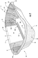
- Fig. 1 illustrates a blank 3 that is used to form a container 5 ( Figs. 2-4 ) having a flange 7 according to a first embodiment of the disclosure.
- the blank 3 has generally straight side edges and semicircular or arc-shaped end edges.
- the blank 3 is for being press formed into the container 5 that, in the illustrated embodiment, is a tray with a generally straight side, a concave side, and convex ends.
- the blank 3 can be press-formed into the container 5 by a forming tool T (shown schematically in Figs. 5A and 5B by way of example), which can be similar to and have similar features and/or components as conventional forming tools such as are disclosed in U.S. Patent Application Publication No.
- the forming tool can have similar features and components such as the forming tool disclosed in International Publication No. WO 2008/049048 , or any other suitable forming tool assembly.
- the blank 3 and the container 5 could be alternatively shaped (e.g., circular, oval, rectangular, irregular, etc.) without departing from the scope of this disclosure.
- the blank 3 of the present disclosure has features that help reduce, prevent, or eliminate delamination and/or buckling of a lamination material in an interior of the container 5 made from the blank at a bottom corner area 9 of the container.
- the blank 3 can be formed from a laminate that includes more than one layer, but alternatively the laminate can be replaced with a single ply of material, such as, but not limited to, paperboard, cardboard, paper, or a polymeric sheet.
- the laminate can include a lamination layer 8, which can be a microwave interactive layer such as is common in MicroRite® containers available from Graphic Packaging International of Marietta, GA.
- the lamination layer can be commonly referred to as, or can have as one of its components, a foil, a microwave shield, or any other term or component that refers to a layer of material suitable for shielding microwave energy and/or causing heating in a microwave oven.
- the lamination layer 8 can be any suitable material that is laminated onto a substrate.
- the lamination layer 8 comprises the inner/interior surface 12 of the blank 3 ( Figs. 1 and 1A ).
- the blank 3 has a substrate or base layer 14 forming an outer/exterior surface 16 ( Fig. 1A ) of the blank 3.
- the lamination layer 8 is supported by, and secured to (e.g., laminated on), the base layer 14, which can be in the form of paperboard, cardboard, polymer, or any other suitable material. Nonetheless and in accordance with the exemplary embodiments, the base layer 14 typically is an uncoated paperboard.
- the lamination layer 8 can be other suitable microwave interactive materials set forth below, or any other suitable material.
- the blank 3 has a longitudinal direction L1 and a lateral direction L2, wherein a longitudinal centerline CL of the blank 3 is generally parallel to the longitudinal direction L1, and a transverse centerline CT of the blank is generally parallel to the lateral direction L2.
- the blank 3 has a central portion 11, an outer edge 13, and a marginal portion 15 between the outer edge 13 and the central portion 11.
- the bottom corner area 9 forms a transition area between the bottom portion 11 and the marginal portion 15.
- the blank 3 can include a first side region 21, a second side region 23, and two end regions 25.
- the marginal portion 15 of the blank 3 includes a plurality of score lines 19.
- the score lines 19 are all positioned in the marginal portion 15 in the end regions 25 such that the score lines extend generally radially from the outer edge 13 of the blank.
- adjacent score lines 19 in respective curved regions 27 can be spaced apart by an angle A1 of at least approximately 5 degrees.
- the angle A1 could be any suitable angle.
- respective straight portions 29 e.g., where the outer edge 13 is generally straight
- the score lines 19 are generally parallel.
- the score lines 19 extend to the outer edge 13 of the blank 3, but the score lines could have a radially outer end point that is spaced in from the outer edge of the blank without departing from the disclosure.
- the score lines 19 are formed on the interior surface 12 such the score lines 19 comprise slight indentations in the interior surface 12 of the blank on the surface of the lamination layer 8 and slight protrusions on the exterior surface 16 of the blank on the outer surface of the base layer 14.
- the score lines 19 could be omitted or could be otherwise shaped, arranged, and/or configured without departing from the disclosure.
- a plurality of score lines 30 can be included in the bottom corner area 9 of the blank 3 for helping to reduce delamination of the lamination layer 8 from the base layer 14.
- the plurality of score lines 30 can include first side score lines 33 extending adjacent the first side region 21, second side score lines 35 extending adjacent the second side region 23, and end score lines 37 extending adjacent each of the end regions 25.
- the score lines 30 are formed on the interior surface 12 such that the score lines 30 comprise slight indentations, slots, or grooves in the interior surface 12 of the blank and slight protrusions on the exterior surface 16 of the blank.
- the first side score lines 33 are generally straight and generally parallel to the longitudinal centerline CL
- the end score lines 37 are generally straight and generally parallel to the transverse centerline CT.
- the second side score lines 35 are curved so that the respective ends of the individual score lines are farther from the longitudinal centerline CL and the first side region 21 than the respective midpoints of the score lines.
- the first and second side score lines 33, 35 can be generally centered on the transverse centerline CT
- the end score lines 37 can be generally centered on the longitudinal centerline CL.
- the score lines 30 could be omitted or could be otherwise shaped, arranged, and/or configured without departing from the disclosure.
- the paperboard base layer 14 of the blank 3 can comprise 18 point paperboard having a thickness of approximately 0.46mm (0.018 inch) and the lamination layer 8 can have a thickness of approximately 0.025mm (0.001 inch) so that the blank 3 has a total thickness T b of approximately 0.48mm (0.019 inch)
- the thickness of a foil within the lamination layer 8 can be approximately 0.007mm (0.000275 inch), for example.
- the thickness of the paperboard base layer 14 can be in the range of approximately 0.33mm (0.013 inch) to approximately 0.72mm (0.030 inch)
- the thickness of the lamination layer 8 can be in the range of approximately 0.013mm (0.0005 inch) to approximately 0.038mm (0.0015 inch)
- the total thickness T b can be in the range of approximately 0.34mm (0.0135 inch) to approximately 0.80mm (0.0315 inch).
- Any of the above noted thicknesses or other dimensions noted above could be larger or smaller than noted or could be inside or outside the listed ranges without departing form the scope of the disclosure.
- All of the dimensional information presented herein is intended to be illustrative of certain aspects of the disclosure and is not intended to limit the scope of the disclosure, as various other embodiments of the disclosure could include dimensions that are greater than or less than the dimensions included herein.
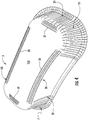
- Figs. 2-4 show one embodiment of the disclosure comprising a container 5 formed from the blank 3.
- the container 5 comprises a generally raised bottom wall 133, a bottom corner 135 that connects the bottom wall to a side wall 137, an upper corner 139 that connects the side wall 137 to the flange 7, and an outer edge 141.
- the bottom wall 133 generally is formed from the bottom portion 11 of the blank 3
- the bottom corner 135 generally is formed from the bottom corner area 9 of the blank
- the side wall 137 and the flange 7 are formed from the marginal portion 15 of the blank.
- the outer radial edge 141 generally can correspond to the outer edge 13 of the blank 3.
- the bottom wall 133 and side wall 137 at least partially define an interior space or cavity 145 of the container 5.
- the lamination layer 8 is on the inner/interior surface 12 of the container 5 and the base layer 14 is on the outer/exterior surface 16 of the container.
- the container 5 is for holding and/or cooking and/or heating a food product (not shown) that is placed in the interior space 145 of the container.
- the flange extends outward from the side wall 137, and an angled upper corner 139 of the flange 7 can be oblique with respect to the side wall 137 and the remainder of the flange 7.
- the upper corner 139 could be curved or otherwise formed or omitted.
- the side wall 137 extends generally upwardly from the bottom corner 135 and the bottom wall 133, and the bottom corner 135 is curved so that the lowest portion of the container 5 is located along the curve of the bottom corner 135. Accordingly, when the container 5 is placed upright on a surface, a portion of the bottom corner 135 rests on the surface and the bottom wall 133 is spaced apart from the surface.
- the side wall 137, the flange 7, and the bottom corner 135 include the first side region 21 in which the side wall 137 and the outer edge 141 are generally straight, the second side region 23 in which the side wall 137 and the outer edge 141 are curved toward the interior 145 of the container 5 (e.g., concave), and the end regions 25 in which the side wall 137 and the outer edge 141 form convex portions connected by a generally straight portion.
- the container 5 could have other shapes and/or dimensions without departing from the disclosure.
- the score lines 19 form overlapped portions or pleats 31.
- the overlapped portions 31 are in the flange 7 of the container and the side wall 137, and extend down the side wall to a location adjacent the bottom wall 133.
- the overlapped portions 31 could be otherwise shaped, arranged, and/or configured without departing from the disclosure.
- the plurality of score lines 30 generally are disposed in the bottom corner 135 and can help prevent the lamination layer 8 from separating from the base layer 14 and extending into the interior 145 of the container 5.
- the first side score lines 33 are generally straight to correspond with the generally straight first side region 21 of the side wall 137
- the second side score lines 35 are curved to correspond with the concave second side region 23 of the side wall
- the end score lines 37 are generally straight to correspond to the generally straight portions of the end regions 25 of the side wall.
- the end scores 37 could be curved with curved portions of the end regions.
- the lamination layer 8 can be generally more resistant to compression - especially compared to the paperboard base layer 14. Since the lamination layer 8 is interior to the base layer 14, the material of the lamination layer 8 can bunch up or buckle at the bottom corner 135 and separate from the base layer 14. For example, micro-layer interactions between the lamination layer and the base layer can cause an adhesive securing the layers together to fail where the adhesive is weaker and/or absent (e.g., due to uneven application). If the scores 30 are omitted, the material of the lamination layer 8 could separate from the base layer 14 and extend into the interior 145 of the container 5.
- the separated portions of the lamination layer could be damaged by an eating utensil, for example, and could be torn away from the interior surface 12 and mix with a food item contained in the container 5. While the materials used in the lamination layer 8 typically are generally inert, the damage to the interior surface of the container 5 can reduce the visual appeal of the container and food items (or other items) contained therein. Additionally, the loose pieces of lamination can cause concern and/or affect the enjoyment of a food item (or other item) in the container by a consumer.
- the scores 30 can help to prevent the lamination layer 8 from buckling into the interior 145.
- the scores 30 generally form grooves in the interior surface 12 of the container so that the lamination layer 8 is stretched somewhat in the bottom corner 135. Accordingly, the lamination layer is compressed into the grooves of the scores 30 when the blank is pressed into the container, and the lamination layer is less likely to delaminate from the base layer 14. What portions of the lamination layer may separate from the base layer will still be disposed within the grooves of the scores 30, and therefore will be compressed into the curve of the bottom corner and at least partially protected from eating utensils, for example, by the grooves.
- any delaminated portions of the lamination layer 8 will be less likely to be torn away from the container and mix with a food item (or other item) in the container. Accordingly, the delamination of the lamination layer 8 is reduced and controlled to help maintain the visual appeal and safety of the container and the food or other items contained in the container.
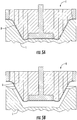
- the blank 3 is formed into the container by conveying a blank and placing the blank in the forming tool T (schematically shown in Figs. 5A and 5B by way of example) with a lower tool assembly L and upper tool assembly U in a separated or open position.
- the forming tool T is used to press form the blank 3 into the container 5 by moving the tool assemblies L, U together, to a closed position ( Fig. 5A , for example).
- the tool assemblies L, U can be separated ( Fig. 5B , for example) to release the container 5.
- the substrate 14 and lamination layer 8 are compressed and formed into the three-dimensional container 5.
- the score lines 19 facilitate forming the flat blank into the three-dimensional container in the forming tool, and the score lines 30 help prevent or reduce buckling of the lamination layer.
- the score lines 19 allow formation of the marginal portion 15 of the blank 3 into the side wall 137 and flange 7 of the container 5.
- the container 5 could be otherwise formed and/or could be formed by any suitable forming tool or forming tools without departing from the disclosure.
- the forming tool T shown schematically in Figs. 5A and 5B is included by way of example only.
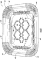
- Fig. 6 is a view of an interior surface 412 of a blank 403 for forming a container 405 ( Figs. 7-9 ) according to a second embodiment of the disclosure.
- the second embodiment is generally similar to the first embodiment, except for variations noted and variations that will be apparent to one of ordinary skill in the art. Accordingly, similar or identical features of the embodiments have been given like or similar reference numbers.
- the blank 403 is generally rectangular with two side regions 421 and two end regions 425.
- the blank 403 has a central portion 411, an outer edge 413, a marginal portion 415, and a bottom corner area 409.
- a plurality of score lines 419 are positioned in the marginal portion 415 in respective curved corners 427 for forming pleats 431 ( Fig. 7 ).
- a plurality of score lines 430 in the corner area 409 can be generally similar to the score lines 30 of the previous embodiment.
- the score lines 430 include generally straight side score lines 433 and end score lines 437.
- the foil of the lamination layer 408 is disposed in a particular pattern 418. Alternatively, the foil can be distributed in any suitable pattern in the lamination layer, could be evenly distributed in the lamination layer, or could be omitted. As shown in Figs.
- the container 405 includes a generally raised bottom wall 533, a bottom corner 535 with the plurality of scores 430, a side wall 537, and a flange 407.
- the container 405 also includes generally straight side regions 421, generally straight end regions 425, and curved corners 438.
- the blank 403 and/or the container 405 could be otherwise shaped, arranged, and/or configured without departing from the disclosure.
- one or more portions of the blank or other constructs described herein or contemplated hereby may be coated with varnish, clay, or other materials, either alone or in combination.
- the coating may then be printed over with product advertising or other information or images.
- the blanks or other constructs also may be selectively coated and/or printed so that less than the entire surface area of the blank or substantially the entire surface area of the blank may be coated and/or printed.
- the containers 5, 405 may cooperate with a lid (not shown) for holding, heating, and/or cooking a food product or other item that is held in the container without departing from the disclosure.
- any of the blanks, containers, or other constructs of this disclosure may optionally include one or more features that alter the effect of microwave energy during the heating or cooking of a food item that is associated with the tray or other construct.
- the blank, tray, container, or other construct may be formed at least partially from one or more microwave energy interactive elements (hereinafter sometimes referred to as "microwave interactive elements") that promote heating, browning and/or crisping of a particular area of the food item, shield a particular area of the food item from microwave energy to prevent overcooking thereof, or transmit microwave energy towards or away from a particular area of the food item.
- microwave interactive elements comprises one or more microwave energy interactive materials or segments arranged in a particular configuration to absorb microwave energy, transmit microwave energy, reflect microwave energy, or direct microwave energy, as needed or desired for a particular construct and food item.
- the microwave energy interactive material may comprise an electroconductive or semiconductive material, for example, a vacuum deposited metal or metal alloy, or a metallic ink, an organic ink, an inorganic ink, a metallic paste, an organic paste, an inorganic paste, or any combination thereof.
- metals and metal alloys that may be suitable include, but are not limited to, aluminum, chromium, copper, inconel alloys (nickel-chromium-molybdenum alloy with niobium), iron, magnesium, nickel, stainless steel, tin, titanium, tungsten, and any combination or alloy thereof.
- the microwave energy interactive material may comprise a metal oxide, for example, oxides of aluminum, iron, and tin, optionally used in conjunction with an electrically conductive material.
- a metal oxide for example, oxides of aluminum, iron, and tin
- ITO indium tin oxide
- the microwave energy interactive material may comprise a suitable electroconductive, semiconductive, or non-conductive artificial dielectric or ferroelectric.
- Artificial dielectrics comprise conductive, subdivided material in a polymeric or other suitable matrix or binder, and may include flakes of an electroconductive metal, for example, aluminum.
- the microwave energy interactive material may be carbon-based, for example, as disclosed in U.S. Patent Nos. 4,943,456 , 5,002,826 , 5,118,747 , and 5,410,135 .
- the microwave energy interactive material may interact with the magnetic portion of the electromagnetic energy in the microwave oven. Correctly chosen materials of this type can self-limit based on the loss of interaction when the Curie temperature of the material is reached.
- An example of such an interactive coating is described in U.S. Patent No. 4,283,427 .
- the microwave energy interactive element may comprise a foil or high optical density evaporated material having a thickness sufficient to reflect a substantial portion of impinging microwave energy.
- Such elements typically are formed from a conductive, reflective metal or metal alloy, for example, aluminum, copper, or stainless steel, in the form of a solid "patch" generally having a thickness of from about 0.00724mm (0.000285 inches) to 0.127mm (0.005 inches), for example, from about 0.0076mm (0.0003 inches) to about 0.075mm (0.003 inches).
- Other such elements may have a thickness of from about 0.009mm (0.00035 inches) to 0.05mm ( 0.002 inches), for example, 0.04mm (0.0016 inches )
- microwave energy reflecting (or reflective) elements may be used as shielding elements where the food item is prone to scorching or drying out during heating.
- smaller microwave energy reflecting elements may be used to diffuse or lessen the intensity of microwave energy.
- One example of a material utilizing such microwave energy reflecting elements is commercially available from Graphic Packaging International, Inc. (Marietta, GA) under the trade name MicroRite® packaging material.
- a plurality of microwave energy reflecting elements may be arranged to form a microwave energy distributing element to direct microwave energy to specific areas of the food item. If desired, the loops may be of a length that causes microwave energy to resonate, thereby enhancing the distribution effect.
- Microwave energy distributing elements are described in U.S. Patent Nos. 6,204,492 , 6,433,322 , 6,552,315 , and 6,677,563 .
- any of the numerous microwave energy interactive elements described herein or contemplated hereby may be substantially continuous, that is, without substantial breaks or interruptions, or may be discontinuous, for example, by including one or more breaks or apertures that transmit microwave energy.
- the breaks or apertures may extend through the entire structure, or only through one or more layers. The number, shape, size, and positioning of such breaks or apertures may vary for a particular application depending on the type of construct being formed, the food item to be heated therein or thereon, the desired degree of heating, browning, and/or crisping, whether direct exposure to microwave energy is needed or desired to attain uniform heating of the food item, the need for regulating the change in temperature of the food item through direct heating, and whether and to what extent there is a need for venting.
- a microwave energy interactive element may include one or more transparent areas to effect dielectric heating of the food item.
- the microwave energy interactive element comprises a susceptor
- such apertures decrease the total microwave energy interactive area, and therefore, decrease the amount of microwave energy interactive material available for heating, browning, and/or crisping the surface of the food item.
- the relative amounts of microwave energy interactive areas and microwave energy transparent areas may be balanced to attain the desired overall heating characteristics for the particular food item.
- one or more portions of a susceptor may be designed to be microwave energy inactive to ensure that the microwave energy is focused efficiently on the areas to be heated, browned, and/or crisped, rather than being lost to portions of the food item not intended to be browned and/or crisped or to the heating environment. Additionally or alternatively, it may be beneficial to create one or more discontinuities or inactive regions to prevent overheating or charring of the food item and/or the construct including the susceptor.
- a susceptor may incorporate one or more "fuse" elements that limit the propagation of cracks in the susceptor, and thereby control overheating, in areas of the susceptor where heat transfer to the food is low and the susceptor might tend to become too hot.
- the size and shape of the fuses may be varied as needed. Examples of susceptors including such fuses are provided, for example, in U.S. Patent No. 5,412,187 , U.S. Patent No. 5,530,231 , U.S. Patent Application Publication No. US 2008/0035634A1, published February 14, 2008 , and PCT Application Publication No. WO 2007/127371, published November 8, 2007 .
- the blanks according to the present invention can be, for example, formed from coated paperboard and similar materials.
- the interior and/or exterior sides of the blanks can be coated with a clay coating.
- the clay coating may then be printed over with product, advertising, price coding, and other information or images.
- the blanks may then be coated with a varnish to protect any information printed on the blanks.
- the blanks may also be coated with, for example, a moisture barrier layer, on either or both sides of the blanks.
- the blanks may be constructed of paperboard of a caliper such that it is heavier and more rigid than ordinary paper.
- the blanks can also be constructed of other materials, such as cardboard, hard paper, or any other material having properties suitable for enabling the carton package to function at least generally as described above.
Landscapes
- Engineering & Computer Science (AREA)
- Mechanical Engineering (AREA)
- Ceramic Engineering (AREA)
- Cartons (AREA)
- Containers Having Bodies Formed In One Piece (AREA)
- Making Paper Articles (AREA)
Claims (26)
- Behälter (5; 405) zum Halten eines Artikels, wobei der Behälter umfasst:eine Laminierungsschicht (8; 408), die wenigstens teilweise an einer Basisschicht (14) befestigt ist;eine Bodenwand (133; 533) und eine Seitenwand (137; 537), die zusammenwirken, um wenigstens teilweise einen Hohlraum (145) des Behälters auszubilden, wobei die Laminierschicht wenigstens teilweise eine Innenfläche (12; 412) des Behälters angrenzend an den Hohlraum aufweist, wobei die Seitenwand (137; 537) einen Endbereich (25; 425) aufweist, wobei wenigstens ein Abschnitt des Endbereichs gekrümmt ist, und wobei eine Vielzahl von Falten (31; 431) in wenigstens dem Endbereich (25; 425) der Seitenwand (137; 537) ausgebildet sind;eine Vielzahl von im Behälter verlaufenden Kerblinien (30, 33, 35, 37; 430, 433, 437) zum wenigstens teilweisen Verringern des Aufwölbens der Laminierschicht (8; 408) in den Hohlraum (145) des Behälters hinein, wobei die Vielzahl von Kerblinien (30, 33, 35, 37; 430, 433, 437) in der Laminierschicht (8; 408) ausgebildet ist und Vertiefungen in der Innenfläche des Behälters (5; 405) bildet, wobei die Laminierschicht (8; 408) in die Vertiefungen hinein zusammengedrückt wird, wobei sich die Vielzahl von Kerblinien (30, 33, 35, 37; 430, 433, 437) quer zu wenigstens einer der Vielzahl von Falten (31; 431) im Endbereich (25; 425) erstreckt, undeine Bodenwand (135; 535), welche die Bodenwand (133; 533) und die Seitenwand (137; 537) verbindet, wobei sich die Vielzahl von Kerblinien (30, 33, 35, 37; 430, 433, 437) wenigstens in die untere Ecke (135; 535) hinein erstreckt.
- Behälter (5; 405) nach Anspruch 1, wobei die Kerblinien (30, 33, 35, 37; 430, 433, 437) der Vielzahl von Kerblinien wenigstens teilweise jeweilige Vorsprünge in einer Außenfläche (16) des Behälters (5; 405) definieren.
- Behälter (5; 405) nach Anspruch 2, wobei die untere Ecke (135; 535) gekrümmt ist und von einer Außenfläche (16) des Behälters (5; 405) her konvex vorliegt, so dass die Laminierschicht (8; 408) im Allgemeinen einen kleineren Krümmungsradius als die Basisschicht (14) hat.
- Behälter (5; 405) nach Anspruch 2, wobei die Seitenwand (137; 537) einen Seitenbereich (21, 23; 421) aufweist und die Vielzahl von Kerblinien (30; 430) eine erste Vielzahl von Kerblinien (33, 35; 433), die sich in der unteren Ecke (135; 535) benachbart dem Seitenbereich (21, 23; 421) der Seitenwand (137; 537) erstreckt, und eine zweite Vielzahl von Kerblinien (37; 437) aufweist, die sich in der unteren Ecke (135, 535) benachbart dem Endbereich (25; 425) der Seitenwand (137; 537) erstreckt, wobei sich die erste Vielzahl von Kerblinien (33, 35; 433) quer zu wenigstens einer der Vielzahl von Falten (31; 431) im Seitenbereich (21, 23; 421) erstreckt und sich die zweite Vielzahl von Kerblinien (37; 437) quer zu wenigstens einer der Vielzahl von Falten (31; 431) im Endbereich (25; 425) erstreckt.
- Behälter (5) nach Anspruch 4, wobei der Seitenbereich (21, 23) der Seitenwand (137) gekrümmt ist und von einer Außenfläche (16) des Behälters her konkav vorliegt und die Kerblinien (35) der ersten Vielzahl von Kerblinien gekrümmt sind.
- Behälter (5; 405) nach Anspruch 1, wobei die Seitenwand (137, 537) einen ersten Seitenbereich (21; 421) und einen zweiten Seitenbereich (23; 421) aufweist und die Vielzahl von Kerblinien (30; 430) eine erste Vielzahl von Kerblinien (33; 433), die sich in der unteren Ecke (135, 535) benachbart dem ersten Seitenbereich (21; 421) der Seitenwand (137; 537) erstreckt, eine zweite Vielzahl von Kerblinien (35; 433), die sich in der unteren Ecke (135, 535) benachbart dem zweiten Seitenbereich (23; 421) der Seitenwand (137; 437) erstreckt, und eine dritte Vielzahl von Kerblinien (37, 437) aufweist, die sich in der unteren Ecke (135; 535) benachbart dem Endbereich (25; 425) der Seitenwand erstreckt, wobei die erste Vielzahl von Kerblinien (33; 433) sich quer zu wenigstens einer der Vielzahl von Falten (31; 431) im ersten Seitenbereich (21; 421) erstreckt, wobei die zweite Vielzahl von Kerblinien (35; 433) sich quer zu auf wenigstens einer der Vielzahl von Falten (31; 431) in dem zweiten Seitenbereich (23; 421) erstreckt und wobei die dritte Vielzahl von Kerblinien (37; 437) sich quer zu wenigstens einer der Vielzahl von Falten (31; 431) im Endbereich (25; 425) erstreckt.
- Behälter (5) nach Anspruch 6, wobei der zweite Seitenbereich (23) der Seitenwand (137) gekrümmt ist und von einer Außenfläche (16) des Behälters (5) her konkav vorliegt und die Kerblinien (35) der zweiten Vielzahl von Kerblinien gekrümmt sind.
- Behälter (5) nach Anspruch 7, wobei ein Endpunkt jeder Kerblinie (35) der zweiten Vielzahl von Kerblinien weiter vom ersten Seitenbereich (21) der Seitenwand (137) entfernt ist als ein Mittelpunkt der jeweiligen Kerblinien der zweiten Vielzahl von Kerblinien.
- Behälter (5) nach Anspruch 7, wobei der erste Seitenbereich (21) der Seitenwand (137) im Allgemeinen gerade ist und die Kerblinien (33) der ersten Vielzahl von Kerblinien im Allgemeinen gerade sind.
- Behälter (5; 405) nach Anspruch 6, wobei sich der Endbereich (25; 425) zwischen dem ersten Seitenbereich (21; 421) und dem zweiten Seitenbereich (23; 421) erstreckt.
- Behälter (5; 405) nach Anspruch 1, wobei sich die Seitenwand (137; 537) allgemein von der unteren Ecke (135; 535) nach oben erstreckt und sich ein Flansch (7; 407) allgemein nach außen von der Seitenwand (137; 537) her erstreckt.
- Behälter (5; 405) nach Anspruch 1, wobei die untere Ecke (135; 535) gekrümmt ist, so dass die Laminierschicht (8; 408) allgemein einen kleineren Krümmungsradius als die Basisschicht (14) in wenigsten der unteren Ecke (135; 535) aufweist.
- Behälter (405) nach Anspruch 1, wobei wenigstens ein Abschnitt der Bodenwand (533) über wenigstens einen Abschnitt der unteren Ecke (535) angehoben ist.
- Zuschnitt (3; 403) zum Ausbilden eines Behälters (5; 405) zum Halten eines Artikels, wobei der Zuschnitt umfasst:eine Laminierungsschicht (8; 408), die wenigstens teilweise an einer Basisschicht (14) befestigt ist;einen Bodenabschnitt (11) und einen Randabschnitt (15; 415), die zusammenwirken, um wenigstens teilweise einen Hohlraum (145) des aus dem Zuschnitt (3; 403) ausgebildeten Behälters (5; 405) auszubilden, wobei die Laminierungsschicht (8; 408) wenigstens teilweise zum Bilden einer Innenfläche (12; 412) des aus dem Zuschnitt (3; 403) ausgebildeten Behälters (5; 405) vorgesehen ist; undeine Vielzahl von sich im Zuschnitt (3; 403) erstreckenden Kerblinien (30, 33, 35, 37; 430, 433, 437) zum wenigstens teilweisen Verringern des Aufwölbens der Laminierschicht (8; 408) in den Hohlraum (145) des aus dem Zuschnitt (3; 403) ausgebildeten Behälters (5; 405) hinein;eine untere Eckfläche (9), die den Bodenabschnitt (11) und den Randabschnitt (15; 415) verbindet, wobei sich die Vielzahl von Kerblinien (30, 33, 35, 37; 430, 433, 437) in wenigstens die untere Eckfläche (9) hinein erstreckt; undeine Vielzahl von Faltenkerben (19; 419) in einem Endbereich (25; 425) des Randabschnitts (15; 415), wobei der Randabschnitt zum wenigstens teilweisen Ausbilden einer Seitenwand (137; 537) in dem aus dem Zuschnitt (3; 403) ausgebildeten Behälter (5; 405) vorgesehen ist, und die Faltenkerben (19; 419) der Vielzahl von Faltenkerben zum Ausbilden der jeweiligen Falten (31; 431) in der Seitenwand (137; 537) des aus dem Zuschnitt ausgebildeten Behälters (5; 405) vorgesehen sind,wobei die Vielzahl von Kerblinien (30, 33, 35, 37; 430, 433, 437) in der Laminierschicht (8; 408) ausgebildet ist und Vertiefungen in der Innenfläche des Zuschnitts bildet, wobei die Laminierschicht in die Vertiefungen hinein zusammengedrückt wird, wobei sich die Vielzahl von Kerblinien (30, 33, 35, 37; 430, 433, 437) quer zu wenigstens einer der Vielzahl von Faltenkerben (31; 431) im Endbereich (25; 425) erstreckt.
- Zuschnitt (3; 403) nach Anspruch 14, wobei die Kerblinien (30, 33, 35, 37; 430, 433, 437) der Vielzahl von Kerblinien wenigstens teilweise entsprechende Vorsprünge in einer Außenfläche (16) des Zuschnitts (3; 403) definieren.
- Zuschnitt (3; 403) nach Anspruch 15, wobei die untere Eckfläche (9) zum Ausbilden einer gekrümmten unteren Ecke (135; 535) vorgesehen ist, wenn der Behälter (5; 405) aus dem Zuschnitt (3; 403) ausgebildet wird, und die untere Ecke von einer aus dem Zuschnitt gebildeten Außenfläche (16) des Behälters (5; 405) her konvex vorliegt, so dass die Laminierschicht (8; 408) allgemein einen kleineren Krümmungsradius als die Basisschicht (14) in der unteren Ecke (135; 535) aufweist, wenn der Behälter (5; 405) aus dem Zuschnitt (3; 403) ausgebildet ist.
- Zuschnitt (3; 403) nach Anspruch 15, wobei der Randabschnitt (15; 415) einen Seitenbereich (21, 23; 421) aufweist und die Vielzahl von Kerblinien (30; 430) eine erste Vielzahl von Kerblinien (33, 35; 433), die sich im unteren Eckbereich (9) benachbart dem Seitenbereich (21, 23; 421) des Randbereichs (15; 415) erstreckt, und eine zweite Vielzahl von Kerblinien (37; 437) aufweist, die sich im unteren Eckbereich (9) benachbart dem Endbereich (25; 425) des Randabschnitts (15; 415) erstreckt, wobei sich die erste Vielzahl von Kerblinien (33, 35; 433) quer zu wenigstens einer der Vielzahl von Falten (31; 431) im Seitenbereich (21, 23; 421) erstreckt und sich die zweite Vielzahl der Kerblinien (37; 437) quer zu wenigstens einer der Vielzahl von Falten (31; 431) im Endbereich (25; 425) erstreckt.
- Zuschnitt (3) nach Anspruch 17, wobei die Kerblinien (35) der ersten Vielzahl von Kerblinien gekrümmt sind und der Seitenbereich (23) des Randabschnitts (15) zum Ausbilden eines gekrümmten Abschnitts der Seitenwand (137) vorgesehen ist, wenn der Behälter (5) aus dem Zuschnitt (3) ausgebildet wird, wobei der gekrümmte Abschnitt der Seitenwand von einer aus dem Zuschnitt (3) gebildeten Außenfläche (16) des Behälters (5) her konkav vorliegt.
- Zuschnitt (3; 403) nach Anspruch 14, wobei der Randabschnitt (15; 415) einen ersten Seitenbereich (21; 421) und einen zweiten Seitenbereich (23; 421) aufweist und die Vielzahl von Kerblinien (30; 430) eine erste Vielzahl von Kerblinien (33; 433), die sich im unteren Eckbereich (9) benachbart dem ersten Seitenbereich (21; 421) des Randabschnitts erstreckt, eine zweite Vielzahl von Kerblinien (35; 433), die sich im unteren Eckbereich (9) angrenzend an den zweiten Seitenbereich (23; 421) des Randabschnitts erstreckt, und eine dritte Vielzahl von Kerblinien (37; 437) aufweist, die sich im unteren Bereich (135, 535) angrenzend an den Endbereich (25; 425) des Randabschnitts erstreckt, wobei sich die erste Vielzahl von Kerblinien (33; 433) quer zu wenigstens einer der Vielzahl von Falten (31; 431) im ersten Seitenbereich (21; 421) erstreckt, wobei sich die zweite Vielzahl von Kerblinien (35; 433) quer zu wenigstens einer der Vielzahl von Falten (31; 431) im zweiten Seitenbereich (23; 421) erstreckt und wobei sich die dritte Vielzahl von Kerblinien (37; 437) quer zu wenigstens einer der Vielzahl von Falten (31; 431) im Endbereich (25; 425) erstreckt.
- Zuschnitt (3) nach Anspruch 19, wobei die Kerblinien (35) der zweiten Vielzahl von Kerblinien gekrümmt sind und der zweite Seitenbereich (23) des Randabschnitts (15) zum Ausbilden eines gekrümmten Abschnitts der Seitenwand (137) vorgesehen ist, wenn der Behälter (5) aus dem Zuschnitt (3) ausgebildet wird, wobei der gekrümmte Abschnitt der Seitenwand (137) von einer Außenfläche (16) des aus dem Zuschnitt (3) gebildeten Behälters (5) her konkav vorliegt.
- Zuschnitt (3) nach Anspruch 20, wobei ein Endpunkt jeder Kerblinie (35) der zweiten Vielzahl von Kerblinien weiter vom ersten Seitenbereich (21) des Randabschnitts (15) entfernt ist als ein Mittelpunkt der jeweiligen Kerblinien der zweiten Vielzahl von Kerblinien.
- Zuschnitt (3) nach Anspruch 20, wobei die Kerblinien (33) der ersten Vielzahl von Kerblinien allgemein geradlinig sind und der erste Seitenbereich (21) des Randabschnitts (15) zum Ausbilden eines allgemein geraden Abschnitts der Seitenwand (137) angeordnet ist, wenn der Behälter (5) aus dem Zuschnitt (3) gebildet wird.
- Zuschnitt (3; 403) nach Anspruch 19, wobei sich der Endbereich (25; 425) zwischen dem ersten Seitenbereich (21; 421) und dem zweiten Seitenbereich (23; 421) erstreckt.
- Zuschnitt (3; 403) nach Anspruch 14, wobei der Randabschnitt (15; 415) des Zuschnitts zum wenigstens teilweisen Ausbilden einer Seitenwand (137; 537) und eines Flansches (7; 407) vorgesehen ist, wenn der Behälter (5; 405) aus dem Zuschnitt (3; 403) gebildet wird.
- Verfahren zur Herstellung eines Behälters (5; 405), umfassend:Erzielen eines Zuschnitts (3; 403), der eine wenigstens teilweise an einer Basisschicht (14) befestigte Laminierschicht (8; 408), eine Vielzahl von Kerblinien (30, 33, 35, 37; 430, 433, 437), einen Bodenabschnitt (11) und einen Randabschnitt (15; 415) umfasst, wobei ein unterer Eckbereich (9) den Bodenabschnitt und den Randabschnitt und eine Vielzahl von Faltenkerben (19; 419) in einem Endbereich (25; 425) des Randabschnitts (15; 415) verbindet, wobei die Vielzahl von Kerblinien (30, 33, 35, 37; 430, 433, 437) in der Laminierschicht (8; 408) ausgebildet ist und Vertiefungen in der Innenfläche (12; 412) des Zuschnitts bildet, wobei die Laminierschicht in die Vertiefungen hinein zusammengedrückt wird, wobei sich die Vielzahl von Kerblinien (30, 33, 35, 37; 430, 433, 437) quer zu wenigstens einer der Vielzahl von Faltenkerben (31; 431) im Endbereich (25; 425) erstreckt; undAusbilden des Behälters (5; 405) mit einer Bodenwand (133; 533) und einer Seitenwand (137, 537) aus dem Zuschnitt (3; 403), wobei das Ausbilden des Behälters das Ausbilden eines Hohlraums (145), der wenigstens teilweise durch die Bodenwand (133; 533) und die Seitenwand (137; 537) definiert ist, Ausbilden wenigstens der Seitenwand (137; 537) aus dem Randabschnitt (15; 415) des Zuschnitts (3; 403), Ausbilden der Bodenwand (133; 533) aus dem Bodenabschnitt (11) des Zuschnitts (3; 403), Ausbilden einer unteren Ecke (135; 535) aus dem unteren Eckbereich (9) des Zuschnitts (3; 403), Ausbilden eines Seitenbereichs (21, 23; 421) der Seitenwand (137; 537) umfasst und wobei die Laminierschicht (8; 408) eine Innenfläche (12; 412) des Behälters (5 (145) benachbart dem Hohlraum (145) umfasst, wobei sich die Vielzahl von Kerblinien (30, 33, 35, 37; 430, 433, 437) in wenigstens der unteren Ecke (135, 535) erstreckt;wobei während des Ausbildens des Behälters (5; 405) die Vielzahl von Kerblinien (30, 33, 35, 37; 430, 433, 437) wenigstens teilweise das Aufwölben der Laminierschicht (8; 408) in den Hohlraum (145) des Behälters (5; 405) verringert und wobei der Seitenbereich (21, 23) gekrümmt und von einer Außenfläche (16) des Behälters her konkav ist.
- Verfahren nach Anspruch 25, wobei die untere Ecke (135; 535) gekrümmt ist und von einer Außenfläche (16) des Behälters her konvex ist, so dass die Laminierschicht (8; 408) allgemein einen kleineren Krümmungsradius aufweist als die Basisschicht (14).
Applications Claiming Priority (3)
| Application Number | Priority Date | Filing Date | Title |
|---|---|---|---|
| US201261795501P | 2012-10-17 | 2012-10-17 | |
| US201261795852P | 2012-10-29 | 2012-10-29 | |
| PCT/US2013/065198 WO2014062779A1 (en) | 2012-10-17 | 2013-10-16 | Container with score lines |
Publications (3)
| Publication Number | Publication Date |
|---|---|
| EP2909090A1 EP2909090A1 (de) | 2015-08-26 |
| EP2909090A4 EP2909090A4 (de) | 2016-05-18 |
| EP2909090B1 true EP2909090B1 (de) | 2017-08-23 |
Family
ID=50474479
Family Applications (1)
| Application Number | Title | Priority Date | Filing Date |
|---|---|---|---|
| EP13847792.2A Active EP2909090B1 (de) | 2012-10-17 | 2013-10-16 | Behälter mit rillen |
Country Status (9)
| Country | Link |
|---|---|
| US (1) | US9371150B2 (de) |
| EP (1) | EP2909090B1 (de) |
| JP (1) | JP6109948B2 (de) |
| CN (1) | CN104736442B (de) |
| BR (1) | BR112015007977B1 (de) |
| CA (1) | CA2884666C (de) |
| ES (1) | ES2647635T3 (de) |
| MX (1) | MX355665B (de) |
| WO (1) | WO2014062779A1 (de) |
Families Citing this family (6)
| Publication number | Priority date | Publication date | Assignee | Title |
|---|---|---|---|---|
| EP2477900B1 (de) * | 2009-09-14 | 2015-08-12 | Graphic Packaging International, Inc. | Rohling und formwerkzeug zum formen eines behälters |
| WO2012065015A2 (en) * | 2010-11-12 | 2012-05-18 | Graphic Packaging International, Inc. | Container, forming tool, and method for forming a container |
| CA2970380C (en) * | 2015-02-27 | 2019-05-14 | William Gilpatrick | Container with coating |
| JP2016198292A (ja) * | 2015-04-10 | 2016-12-01 | 吉田テクノワークス株式会社 | 樹脂製食器および樹脂製食器の製造方法 |
| WO2017100557A1 (en) * | 2015-12-11 | 2017-06-15 | Graphic Packaging International, Inc. | Container with absorption features |
| US20200385161A1 (en) * | 2019-06-07 | 2020-12-10 | Glenn H. Morris, Jr. | Container with Sidewall Pillars |
Family Cites Families (155)
| Publication number | Priority date | Publication date | Assignee | Title |
|---|---|---|---|---|
| US1022882A (en) | 1911-03-18 | 1912-04-09 | Ludwig J C Schwenn | Plate. |
| US1986824A (en) | 1933-01-09 | 1935-01-08 | American Lace Paper Company | Receptacle of molded pulp |
| US2387778A (en) | 1942-06-04 | 1945-10-30 | Stocking Willard Yates | Method of molding containers |
| GB609142A (en) | 1946-03-06 | 1948-09-27 | Oscar Legg | Improvements in and relating to bins for storing and transporting tobacco |
| US2522397A (en) | 1947-06-18 | 1950-09-12 | Helen A Palmer | Baking utensil |
| US2634880A (en) | 1951-05-23 | 1953-04-14 | William H Gravatt | Disposable liner for garbage cans |
| US2831623A (en) | 1955-06-24 | 1958-04-22 | Michael A Lavigne | Prefabricated milk container |
| US2997927A (en) | 1959-02-09 | 1961-08-29 | Peerless Machine & Tool Co Inc | Formed paper dish and method for making same |
| GB961204A (en) | 1959-11-17 | 1964-06-17 | Walther Zarges | Improvements in or relating to nestable containers |
| US3099377A (en) | 1960-08-17 | 1963-07-30 | American Can Co | Dish or the like |
| US3033434A (en) | 1961-03-27 | 1962-05-08 | Peerless Machine & Tool Co Inc | Pressed article with smooth take-up curved zones |
| US3195770A (en) | 1963-02-18 | 1965-07-20 | Holley Plastics Company | Plastic capsule packaging |
| US3229886A (en) | 1963-07-31 | 1966-01-18 | Reynolds Metals Co | Pie plate construction |
| US3315018A (en) | 1963-11-26 | 1967-04-18 | Sweetheart Plastics | Method of making foamed plastic containers |
| US3220631A (en) | 1964-04-23 | 1965-11-30 | Diamond Int Corp | Display tray |
| US3286876A (en) | 1964-06-15 | 1966-11-22 | Goodyear Aerospace Corp | Containers |
| CA942244A (en) | 1968-04-18 | 1974-02-19 | Robert L. Calder | Fish packing system |
| DE6809049U (de) | 1968-11-28 | 1969-03-13 | Bellaplast Heller & Co | Trinkbecher aus duennwandigem kunststoff |
| US3530917A (en) | 1969-02-27 | 1970-09-29 | Monsanto Co | Package |
| US3669305A (en) | 1970-02-05 | 1972-06-13 | Phillips Petroleum Co | Container and closure therefor |
| GB1348370A (en) | 1970-05-13 | 1974-03-13 | Airfix Ind Ltd | Method of making containers |
| US3680733A (en) | 1970-07-20 | 1972-08-01 | Samuel J Winslow | Hollowware construction |
| US3836042A (en) | 1970-07-27 | 1974-09-17 | Foster Grant Co Inc | Nestable container |
| US3850340A (en) | 1970-11-04 | 1974-11-26 | Reynolds Metals Co | Nestable container and apparatus for and method of making same |
| US3684633A (en) | 1971-01-05 | 1972-08-15 | Mobil Oil Corp | Laminated thermoplastic foam-film dish |
| JPS509335Y2 (de) | 1971-04-15 | 1975-03-20 | ||
| GB1376603A (en) | 1972-02-24 | 1974-12-11 | Drg Packaging Ltd | Denestable containers |
| GB1470977A (en) | 1973-08-07 | 1977-04-21 | Ici Ltd | Container |
| FR2266638A1 (en) | 1974-04-05 | 1975-10-31 | Plasturgie Atel | Stackable boxes for vegetables etc. - are reversible so projections and recesses hold them on top or inside each other |
| US4026458A (en) | 1975-03-27 | 1977-05-31 | International Paper Company | Deep drawn paperboard container and process for making it |
| IE42906B1 (en) | 1975-08-01 | 1980-11-05 | Mars Ltd | Nestable plastics containers |
| US3968921A (en) | 1975-08-06 | 1976-07-13 | Restaurant Technology, Inc. | Foam package for breakfast foods |
| US4051707A (en) | 1976-02-02 | 1977-10-04 | Kraft, Inc. | Method and apparatus for making drawn containers |
| US4096947A (en) | 1977-01-21 | 1978-06-27 | Milton Morse | Synthetic resinous nesting cup construction |
| JPS54116059U (de) | 1978-02-01 | 1979-08-14 | ||
| JPS5741133Y2 (de) | 1978-02-21 | 1982-09-09 | ||
| US4202464A (en) | 1978-02-22 | 1980-05-13 | Placon Corporation | Recloseable container |
| US4284023A (en) | 1978-03-03 | 1981-08-18 | Japan Crown Cork Co., Ltd. | Method of producing an easily openable container closure having a shell and a sealing member |
| US4183435A (en) | 1978-08-24 | 1980-01-15 | Champion International Corporation | Polymeric multiple-layer sheet material |
| US4381278A (en) * | 1978-12-11 | 1983-04-26 | James River-Dixie/Northern, Inc. | Method for forming a coated paperboard container |
| GB2061699B (en) | 1979-07-17 | 1984-02-22 | Mono Containers Ltd | Containers particularly cups |
| JPS5665866U (de) | 1979-10-26 | 1981-06-02 | ||
| DE8011020U1 (de) | 1980-04-23 | 1980-09-11 | Novoplast Verpackungen | Verpackungsbecher fuer kleinere Mengen |
| US4420081A (en) | 1981-06-22 | 1983-12-13 | Dart Container Corporation | Step-wall nestable cup |
| DE3175548D1 (en) | 1981-12-18 | 1986-12-11 | Champion Int Corp | An apparatus and method for forming a paperboard receptacle |
| US4721500A (en) | 1982-04-13 | 1988-01-26 | James River-Dixie Northern, Inc. | Method of forming a rigid paper-board container |
| US4609140C1 (en) | 1982-04-13 | 2002-04-16 | James River Corp | Rigid paperboard container and method and apparatus for producing same |
| JPS5975004U (ja) | 1982-11-09 | 1984-05-22 | 浦田鉄工株式会社 | 割バシ製造機 |
| JPS59117835U (ja) | 1983-01-29 | 1984-08-09 | 日野自動車株式会社 | リア・エンジン・バスに使用されるフアン・シユラウド |
| DE3483543D1 (de) | 1983-06-03 | 1990-12-13 | Fp Corp | Behaelter. |
| JPS6096234U (ja) | 1983-12-07 | 1985-07-01 | 伊藤金属工業株式会社 | 広口アルミ容器 |
| AU572632B2 (en) | 1984-03-20 | 1988-05-12 | James River Corporation Of Virginia | Rigid paperboard container |
| US4721499C1 (en) | 1984-03-20 | 2002-06-04 | Fort James Corp | Method of producing a rigid paperboard container |
| NL8500720A (nl) | 1984-05-22 | 1985-07-01 | Highland Supply Corp | Systeem voor het vormen van voorwerpen. |
| GB2171046A (en) | 1985-02-14 | 1986-08-20 | Metal Box Plc | Containers |
| US5105947A (en) | 1985-10-04 | 1992-04-21 | Plastech International, Inc. | Container having a replaceable pallet base |
| GB8612537D0 (en) | 1986-05-22 | 1986-07-02 | Gen Foods Ltd | Containers |
| FR2599002B3 (fr) | 1986-05-22 | 1988-12-09 | Rigolet Charles Fils | Barquette en matiere synthetique obturee par un film |
| US4832676A (en) | 1986-12-08 | 1989-05-23 | James River-Norwalk, Inc. | Method and apparatus for forming paperboard containers |
| USRE34683E (en) | 1987-03-10 | 1994-08-02 | James River Corporation Of Virginia | Control of microwave interactive heating by patterned deactivation |
| US4865921A (en) | 1987-03-10 | 1989-09-12 | James Riker Corporation Of Virginia | Microwave interactive laminate |
| US4775771A (en) | 1987-07-30 | 1988-10-04 | James River Corporation | Sleeve for crisping and browning of foods in a microwave oven and package and method utilizing same |
| US4900594A (en) * | 1987-09-17 | 1990-02-13 | International Paper Company | Pressure formed paperboard tray with oriented polyester film interior |
| US4935089A (en) | 1987-10-30 | 1990-06-19 | W. R. Grace & Co.-Conn. | Method of making a thermoformable barrier sheet |
| DE3737052A1 (de) | 1987-10-31 | 1989-05-11 | Nadler Werke Gmbh Feinkostfabr | Verpackung |
| CA1292934C (en) | 1988-05-20 | 1991-12-10 | Donald G. Beckett | Microwave heating material |
| US5410135A (en) | 1988-09-01 | 1995-04-25 | James River Paper Company, Inc. | Self limiting microwave heaters |
| US4890439A (en) | 1988-11-09 | 1990-01-02 | James River Corporation | Flexible disposable material for forming a food container for microwave cooking |
| GB8827759D0 (en) | 1988-11-28 | 1988-12-29 | Beckett D E | Selective microwave heating material-ii |
| US5519195A (en) | 1989-02-09 | 1996-05-21 | Beckett Technologies Corp. | Methods and devices used in the microwave heating of foods and other materials |
| JPH0728883Y2 (ja) | 1989-06-30 | 1995-07-05 | 石垣機工株式会社 | ▲ろ▼過機の集水装置 |
| US4967908A (en) | 1989-11-17 | 1990-11-06 | The Vollrath Company, Inc. | Apparatus for transporting articles |
| CA2009207A1 (en) | 1990-02-02 | 1991-08-02 | D. Gregory Beckett | Controlled heating of foodstuffs by microwave energy |
| US5190209A (en) | 1990-05-18 | 1993-03-02 | Sonoco Products Company | Plastic chime overlay for fibre drum |
| US5230939A (en) * | 1990-09-04 | 1993-07-27 | James River Corporation Of Virginia | Forming of pressed trays |
| US5176284A (en) | 1990-11-08 | 1993-01-05 | Primtec | Reduction of flexure in a plastic container having a thin flexible side wall |
| US5266386A (en) | 1991-02-14 | 1993-11-30 | Beckett Industries Inc. | Demetallizing procedure |
| US5628921A (en) | 1991-02-14 | 1997-05-13 | Beckett Technologies Corp. | Demetallizing procedure |
| CA2041062C (en) | 1991-02-14 | 2000-11-28 | D. Gregory Beckett | Demetallizing procedure |
| US5213902A (en) | 1991-02-19 | 1993-05-25 | Beckett Industries Inc. | Microwave oven package |
| US5221419A (en) | 1991-02-19 | 1993-06-22 | Beckett Industries Inc. | Method for forming laminate for microwave oven package |
| US5260537A (en) | 1991-06-17 | 1993-11-09 | Beckett Industries Inc. | Microwave heating structure |
| US5203491A (en) * | 1991-10-17 | 1993-04-20 | James River Corporation Of Virginia | Bake-in press-formed container |
| GB9201932D0 (en) | 1992-01-29 | 1992-03-18 | Beckett Ind Inc | Novel microwave heating structure |
| US5269717A (en) | 1992-11-12 | 1993-12-14 | Genin Trudeau | Dishware having a liquid-filled rim and eating implements |
| US5523042A (en) | 1993-02-10 | 1996-06-04 | Solo Cup Company | Method of making plastic plate with rolled edge rim |
| US5424517A (en) | 1993-10-27 | 1995-06-13 | James River Paper Company, Inc. | Microwave impedance matching film for microwave cooking |
| US5617972A (en) | 1994-03-25 | 1997-04-08 | Playtex Products Inc. | Nurser liner |
| JP3013843U (ja) | 1994-08-22 | 1995-07-25 | 新高化学工業株式会社 | 使い捨て鍋 |
| GB9420292D0 (en) | 1994-10-07 | 1994-11-23 | Nicholl Food Packaging Limited | Improvements in and relating to food containers |
| JP2743060B2 (ja) | 1994-12-08 | 1998-04-22 | 有限会社都波岐精工 | 部品トレー |
| FR2733715B3 (fr) | 1995-05-04 | 1997-06-13 | Monoplast Sa | Procede de fabrication de pieces thermoplastiques et pieces obtenues selon ce procede |
| US5782376A (en) | 1995-05-25 | 1998-07-21 | General Mills, Inc. | Thermoformed plastic containers and their method of manufacture |
| JP3016003B2 (ja) | 1995-06-07 | 2000-03-06 | 株式会社不二コーン製作所 | 食品等の縁厚モールドトレー並びにその製造方法並びにその製造装置 |
| JPH08337235A (ja) | 1995-06-14 | 1996-12-24 | Gifu Plast Ind Co Ltd | 合成樹脂製容器 |
| US5938112A (en) | 1995-08-28 | 1999-08-17 | Fort James Corporation | Rigid paperboard container |
| DE29602348U1 (de) | 1996-02-10 | 1996-03-28 | F Luce Verpackungswerk Fa | Schalenartiges Formteil |
| US5759422A (en) | 1996-02-14 | 1998-06-02 | Fort James Corporation | Patterned metal foil laminate and method for making same |
| US5800724A (en) | 1996-02-14 | 1998-09-01 | Fort James Corporation | Patterned metal foil laminate and method for making same |
| JPH09254948A (ja) | 1996-03-28 | 1997-09-30 | Toyo Echo Kk | 電子レンジ加熱用容器 |
| US6270003B1 (en) | 1996-04-03 | 2001-08-07 | Hirano Shiki Co., Ltd. | Cake container |
| JP3448435B2 (ja) | 1996-07-01 | 2003-09-22 | 東洋アルミホイルプロダクツ株式会社 | 紙容器及び紙容器の成形方法 |
| US6150646A (en) | 1996-08-26 | 2000-11-21 | Graphic Packaging Corporation | Microwavable container having active microwave energy heating elements for combined bulk and surface heating |
| WO1998008752A2 (en) | 1996-08-26 | 1998-03-05 | Fort James Corporation | Microwavable package |
| US20010005550A1 (en) | 1998-03-10 | 2001-06-28 | Jorgen Bengtsson | Laminated packaging materials and packaging containers produced therefrom |
| SE514845C2 (sv) | 1996-09-04 | 2001-04-30 | Tetra Laval Holdings & Finance | Biologiskt nedbrytbart förpackningslaminat, sätt att framställa förpackningslaminatet samt av förpackningslaminatet framställda förpackningsbehållare |
| WO1998033724A1 (en) | 1997-01-29 | 1998-08-06 | Fort James Corporation | Microwave oven heating element having broken loops |
| JP3057020B2 (ja) | 1997-03-03 | 2000-06-26 | 正 鈴木 | マンホール蓋用受枠の昇降装置 |
| US6325213B1 (en) | 1997-11-20 | 2001-12-04 | General Mills, Inc. | Plastic container for food products |
| US6213301B1 (en) | 1997-11-20 | 2001-04-10 | General Mills, Inc. | Plastic container for food products |
| US6414290B1 (en) | 1998-03-19 | 2002-07-02 | Graphic Packaging Corporation | Patterned microwave susceptor |
| US5934472A (en) | 1998-04-06 | 1999-08-10 | Tekni-Plex, Inc. | Processor tray |
| JP3513644B2 (ja) | 1998-07-31 | 2004-03-31 | 技研化成株式会社 | 食品用容器 |
| JP4170474B2 (ja) | 1998-11-05 | 2008-10-22 | 大日本印刷株式会社 | 電子レンジ加熱用容器 |
| JP2000238760A (ja) | 1999-02-16 | 2000-09-05 | Toppan Printing Co Ltd | 紙トレー |
| US6568534B2 (en) | 1999-04-01 | 2003-05-27 | The Vollrath Company, L.L.C. | Covered pan system |
| US6349843B1 (en) | 1999-04-01 | 2002-02-26 | The Vollrath Company Llc | Pan removal ramp |
| JP2000335550A (ja) | 1999-05-26 | 2000-12-05 | Toppan Printing Co Ltd | 紙容器 |
| US6311431B1 (en) | 1999-06-23 | 2001-11-06 | Southpac Trust International, Inc. | Pot cover with preset folds |
| US6204492B1 (en) | 1999-09-20 | 2001-03-20 | Graphic Packaging Corporation | Abuse-tolerant metallic packaging materials for microwave cooking |
| US6433322B2 (en) | 1999-09-20 | 2002-08-13 | Graphic Packaging Corporation | Abuse-tolerant metallic packaging materials for microwave cooking |
| JP2001213420A (ja) | 2000-02-07 | 2001-08-07 | Giken Kasei Kk | 包装容器 |
| JP4580505B2 (ja) | 2000-05-19 | 2010-11-17 | 大日本印刷株式会社 | 密封型紙トレー容器の製造方法 |
| US7048176B2 (en) | 2000-10-27 | 2006-05-23 | Fort James Corporation | Deep dish disposable container |
| US6988654B2 (en) | 2001-01-18 | 2006-01-24 | Graphic Packaging International, Inc. | Container with improved stacking/denesting capability |
| US20020179612A1 (en) * | 2001-04-25 | 2002-12-05 | Toussant John William | Invertible food container |
| US6717121B2 (en) | 2001-09-28 | 2004-04-06 | Graphic Packaging International, Inc. | Patterned microwave susceptor element and microwave container incorporating same |
| DE10149143A1 (de) | 2001-10-05 | 2003-04-30 | Henkel Kgaa | Wasserlöslicher Behälter mit umlaufendem Rand |
| US6677563B2 (en) | 2001-12-14 | 2004-01-13 | Graphic Packaging Corporation | Abuse-tolerant metallic pattern arrays for microwave packaging materials |
| US6715630B2 (en) | 2002-01-23 | 2004-04-06 | Fort James Corporation | Disposable food container with a linear sidewall profile and an arcuate outer flange |
| CA2474927C (en) | 2002-02-08 | 2010-03-30 | Graphic Packaging International, Inc. | Insulating microwave interactive packaging |
| EP2353835B1 (de) | 2002-03-15 | 2012-09-26 | Graphic Packaging International, Inc. | Ein Formwerkzeug und Verfahren zum Herstellen eines Behälters mit einem spritzgegossenen Merkmal. |
| JP2003312631A (ja) * | 2002-04-23 | 2003-11-06 | Rengo Co Ltd | 段ボール成形体及びその成形方法 |
| US7337943B2 (en) | 2002-06-27 | 2008-03-04 | Dixie Consumer Products Llc | Disposable servingware containers with flange tabs |
| US7862318B2 (en) | 2002-10-08 | 2011-01-04 | Graphic Packaging International, Inc. | Container having a rim or other feature encapsulated by or formed from injection-molded material |
| US7121422B2 (en) | 2002-10-21 | 2006-10-17 | Solo Cup Operating Corporation | Disposable plate having improved ergonomics |
| US6718788B1 (en) | 2003-03-04 | 2004-04-13 | Building Materials Investment Corporation | Method for producing a drain pan and drain pan produced thereby |
| JP4369770B2 (ja) | 2003-06-16 | 2009-11-25 | 株式会社秀英 | 紙製容器 |
| EP1687213A2 (de) | 2003-11-11 | 2006-08-09 | Graphic Packaging International, Inc. | Ineinanderstapelbarer behälter mit gleichförmigen stapelmerkmalen |
| ITTO20040382A1 (it) * | 2004-06-09 | 2004-09-09 | Comital Cofresco S P A | Vaschetta in cartoncino per alimenti |
| FI117933B (fi) * | 2005-09-29 | 2007-04-30 | Stora Enso Oyj | Menetelmä kartonkivuoan valmistamiseksi, vuoka-aihio sekä siitä menetelmän mukaisesti saatava vuoka |
| KR100707268B1 (ko) | 2005-10-08 | 2007-04-16 | 삼성전자주식회사 | 영상보간장치 및 영상보간방법 |
| EP1993918B1 (de) * | 2006-01-13 | 2011-07-13 | Solo Cup Operating Corporation | Kartonage mit erhöhter steifigkeit |
| GB2435029A (en) * | 2006-02-10 | 2007-08-15 | Andre Philip Wilkins | Paperboard packing trays for hermetic sealing |
| WO2008049048A2 (en) | 2006-10-18 | 2008-04-24 | Graphic Packaging International, Inc. | Tool for forming a three dimensional article or container |
| JP2008174278A (ja) * | 2007-01-19 | 2008-07-31 | Nomura Sogo Shoji Kk | 加工食品用容器 |
| CA2707054C (en) | 2007-12-28 | 2013-02-26 | Graphic Packaging International, Inc. | Injection-molded composite construct and tool for forming construct |
| JP5197758B2 (ja) | 2007-12-31 | 2013-05-15 | グラフィック パッケージング インターナショナル インコーポレイテッド | 構造体を成形するための工具 |
| US7980450B2 (en) | 2008-01-04 | 2011-07-19 | Dixie Consumer Products Llc | Disposable pressware prepared from wax-infused paperboard |
| US7975871B2 (en) | 2008-04-04 | 2011-07-12 | Graphic Packaging International, Inc. | Container with injection-molded feature and tool for forming container |
| US8474689B2 (en) * | 2008-12-15 | 2013-07-02 | Dixie Consumer Products Llc | Method for in-die lamination of plural layers of material and paper-containing product made thereby |
| CA2771557C (en) | 2009-08-26 | 2017-05-09 | Graphic Packaging International, Inc. | Container blank and container with denesting feature |
| EP2477900B1 (de) | 2009-09-14 | 2015-08-12 | Graphic Packaging International, Inc. | Rohling und formwerkzeug zum formen eines behälters |
| EP2388201A1 (de) * | 2010-05-20 | 2011-11-23 | Saica Pack, S.L. | Herstellungsverfahren zur Herstellung von warmgeformten Tabletts und mit dem Verfahren erhaltenes Tablett |
| SE536107C2 (sv) * | 2010-08-26 | 2013-05-07 | Stora Enso Oyj | Metod för att bilda en förpackning, en förpackning och ett förpackningsämne |
-
2013
- 2013-10-16 US US14/055,127 patent/US9371150B2/en active Active
- 2013-10-16 JP JP2015537786A patent/JP6109948B2/ja not_active Expired - Fee Related
- 2013-10-16 ES ES13847792.2T patent/ES2647635T3/es active Active
- 2013-10-16 MX MX2015004473A patent/MX355665B/es active IP Right Grant
- 2013-10-16 CN CN201380054913.5A patent/CN104736442B/zh active Active
- 2013-10-16 CA CA2884666A patent/CA2884666C/en active Active
- 2013-10-16 EP EP13847792.2A patent/EP2909090B1/de active Active
- 2013-10-16 WO PCT/US2013/065198 patent/WO2014062779A1/en active Application Filing
- 2013-10-16 BR BR112015007977-6A patent/BR112015007977B1/pt active IP Right Grant
Non-Patent Citations (1)
| Title |
|---|
| None * |
Also Published As
| Publication number | Publication date |
|---|---|
| JP6109948B2 (ja) | 2017-04-05 |
| US9371150B2 (en) | 2016-06-21 |
| CA2884666C (en) | 2017-12-19 |
| MX2015004473A (es) | 2015-07-14 |
| US20140103038A1 (en) | 2014-04-17 |
| WO2014062779A1 (en) | 2014-04-24 |
| CN104736442B (zh) | 2016-08-24 |
| CA2884666A1 (en) | 2014-04-24 |
| MX355665B (es) | 2018-04-25 |
| BR112015007977A2 (pt) | 2017-07-04 |
| CN104736442A (zh) | 2015-06-24 |
| BR112015007977B1 (pt) | 2021-08-03 |
| JP2015532248A (ja) | 2015-11-09 |
| EP2909090A1 (de) | 2015-08-26 |
| ES2647635T3 (es) | 2017-12-22 |
| EP2909090A4 (de) | 2016-05-18 |
Similar Documents
| Publication | Publication Date | Title |
|---|---|---|
| US10022932B2 (en) | Container, forming tool, and method for forming a container | |
| EP2909090B1 (de) | Behälter mit rillen | |
| US9174789B2 (en) | Container with heating features | |
| WO2018017783A1 (en) | Container with liner | |
| US11084626B2 (en) | Method of forming a container | |
| US10479584B2 (en) | Microwave packaging | |
| CA3004182C (en) | Microwave package | |
| AU2022233153A1 (en) | Tray with compartments | |
| US20170096256A1 (en) | Packaging For Food Product |
Legal Events
| Date | Code | Title | Description |
|---|---|---|---|
| PUAI | Public reference made under article 153(3) epc to a published international application that has entered the european phase |
Free format text: ORIGINAL CODE: 0009012 |
|
| 17P | Request for examination filed |
Effective date: 20150511 |
|
| AK | Designated contracting states |
Kind code of ref document: A1 Designated state(s): AL AT BE BG CH CY CZ DE DK EE ES FI FR GB GR HR HU IE IS IT LI LT LU LV MC MK MT NL NO PL PT RO RS SE SI SK SM TR |
|
| AX | Request for extension of the european patent |
Extension state: BA ME |
|
| DAX | Request for extension of the european patent (deleted) | ||
| RA4 | Supplementary search report drawn up and despatched (corrected) |
Effective date: 20160420 |
|
| RIC1 | Information provided on ipc code assigned before grant |
Ipc: B65D 1/26 20060101AFI20160414BHEP Ipc: B65D 1/40 20060101ALI20160414BHEP |
|
| GRAP | Despatch of communication of intention to grant a patent |
Free format text: ORIGINAL CODE: EPIDOSNIGR1 |
|
| INTG | Intention to grant announced |
Effective date: 20170328 |
|
| GRAS | Grant fee paid |
Free format text: ORIGINAL CODE: EPIDOSNIGR3 |
|
| GRAA | (expected) grant |
Free format text: ORIGINAL CODE: 0009210 |
|
| AK | Designated contracting states |
Kind code of ref document: B1 Designated state(s): AL AT BE BG CH CY CZ DE DK EE ES FI FR GB GR HR HU IE IS IT LI LT LU LV MC MK MT NL NO PL PT RO RS SE SI SK SM TR |
|
| REG | Reference to a national code |
Ref country code: GB Ref legal event code: FG4D |
|
| REG | Reference to a national code |
Ref country code: CH Ref legal event code: EP |
|
| REG | Reference to a national code |
Ref country code: AT Ref legal event code: REF Ref document number: 921051 Country of ref document: AT Kind code of ref document: T Effective date: 20170915 |
|
| REG | Reference to a national code |
Ref country code: IE Ref legal event code: FG4D |
|
| REG | Reference to a national code |
Ref country code: DE Ref legal event code: R096 Ref document number: 602013025617 Country of ref document: DE |
|
| REG | Reference to a national code |
Ref country code: FR Ref legal event code: PLFP Year of fee payment: 5 |
|
| REG | Reference to a national code |
Ref country code: ES Ref legal event code: FG2A Ref document number: 2647635 Country of ref document: ES Kind code of ref document: T3 Effective date: 20171222 |
|
| REG | Reference to a national code |
Ref country code: NL Ref legal event code: MP Effective date: 20170823 |
|
| REG | Reference to a national code |
Ref country code: LT Ref legal event code: MG4D |
|
| REG | Reference to a national code |
Ref country code: AT Ref legal event code: MK05 Ref document number: 921051 Country of ref document: AT Kind code of ref document: T Effective date: 20170823 |
|
| PG25 | Lapsed in a contracting state [announced via postgrant information from national office to epo] |
Ref country code: AT Free format text: LAPSE BECAUSE OF FAILURE TO SUBMIT A TRANSLATION OF THE DESCRIPTION OR TO PAY THE FEE WITHIN THE PRESCRIBED TIME-LIMIT Effective date: 20170823 Ref country code: NO Free format text: LAPSE BECAUSE OF FAILURE TO SUBMIT A TRANSLATION OF THE DESCRIPTION OR TO PAY THE FEE WITHIN THE PRESCRIBED TIME-LIMIT Effective date: 20171123 Ref country code: LT Free format text: LAPSE BECAUSE OF FAILURE TO SUBMIT A TRANSLATION OF THE DESCRIPTION OR TO PAY THE FEE WITHIN THE PRESCRIBED TIME-LIMIT Effective date: 20170823 Ref country code: NL Free format text: LAPSE BECAUSE OF FAILURE TO SUBMIT A TRANSLATION OF THE DESCRIPTION OR TO PAY THE FEE WITHIN THE PRESCRIBED TIME-LIMIT Effective date: 20170823 Ref country code: SE Free format text: LAPSE BECAUSE OF FAILURE TO SUBMIT A TRANSLATION OF THE DESCRIPTION OR TO PAY THE FEE WITHIN THE PRESCRIBED TIME-LIMIT Effective date: 20170823 Ref country code: HR Free format text: LAPSE BECAUSE OF FAILURE TO SUBMIT A TRANSLATION OF THE DESCRIPTION OR TO PAY THE FEE WITHIN THE PRESCRIBED TIME-LIMIT Effective date: 20170823 Ref country code: FI Free format text: LAPSE BECAUSE OF FAILURE TO SUBMIT A TRANSLATION OF THE DESCRIPTION OR TO PAY THE FEE WITHIN THE PRESCRIBED TIME-LIMIT Effective date: 20170823 |
|
| PG25 | Lapsed in a contracting state [announced via postgrant information from national office to epo] |
Ref country code: BG Free format text: LAPSE BECAUSE OF FAILURE TO SUBMIT A TRANSLATION OF THE DESCRIPTION OR TO PAY THE FEE WITHIN THE PRESCRIBED TIME-LIMIT Effective date: 20171123 Ref country code: GR Free format text: LAPSE BECAUSE OF FAILURE TO SUBMIT A TRANSLATION OF THE DESCRIPTION OR TO PAY THE FEE WITHIN THE PRESCRIBED TIME-LIMIT Effective date: 20171124 Ref country code: RS Free format text: LAPSE BECAUSE OF FAILURE TO SUBMIT A TRANSLATION OF THE DESCRIPTION OR TO PAY THE FEE WITHIN THE PRESCRIBED TIME-LIMIT Effective date: 20170823 Ref country code: IS Free format text: LAPSE BECAUSE OF FAILURE TO SUBMIT A TRANSLATION OF THE DESCRIPTION OR TO PAY THE FEE WITHIN THE PRESCRIBED TIME-LIMIT Effective date: 20171223 Ref country code: LV Free format text: LAPSE BECAUSE OF FAILURE TO SUBMIT A TRANSLATION OF THE DESCRIPTION OR TO PAY THE FEE WITHIN THE PRESCRIBED TIME-LIMIT Effective date: 20170823 Ref country code: PL Free format text: LAPSE BECAUSE OF FAILURE TO SUBMIT A TRANSLATION OF THE DESCRIPTION OR TO PAY THE FEE WITHIN THE PRESCRIBED TIME-LIMIT Effective date: 20170823 |
|
| PG25 | Lapsed in a contracting state [announced via postgrant information from national office to epo] |
Ref country code: CZ Free format text: LAPSE BECAUSE OF FAILURE TO SUBMIT A TRANSLATION OF THE DESCRIPTION OR TO PAY THE FEE WITHIN THE PRESCRIBED TIME-LIMIT Effective date: 20170823 Ref country code: RO Free format text: LAPSE BECAUSE OF FAILURE TO SUBMIT A TRANSLATION OF THE DESCRIPTION OR TO PAY THE FEE WITHIN THE PRESCRIBED TIME-LIMIT Effective date: 20170823 Ref country code: DK Free format text: LAPSE BECAUSE OF FAILURE TO SUBMIT A TRANSLATION OF THE DESCRIPTION OR TO PAY THE FEE WITHIN THE PRESCRIBED TIME-LIMIT Effective date: 20170823 |
|
| REG | Reference to a national code |
Ref country code: DE Ref legal event code: R097 Ref document number: 602013025617 Country of ref document: DE |
|
| PG25 | Lapsed in a contracting state [announced via postgrant information from national office to epo] |
Ref country code: SK Free format text: LAPSE BECAUSE OF FAILURE TO SUBMIT A TRANSLATION OF THE DESCRIPTION OR TO PAY THE FEE WITHIN THE PRESCRIBED TIME-LIMIT Effective date: 20170823 Ref country code: SM Free format text: LAPSE BECAUSE OF FAILURE TO SUBMIT A TRANSLATION OF THE DESCRIPTION OR TO PAY THE FEE WITHIN THE PRESCRIBED TIME-LIMIT Effective date: 20170823 Ref country code: EE Free format text: LAPSE BECAUSE OF FAILURE TO SUBMIT A TRANSLATION OF THE DESCRIPTION OR TO PAY THE FEE WITHIN THE PRESCRIBED TIME-LIMIT Effective date: 20170823 Ref country code: IT Free format text: LAPSE BECAUSE OF FAILURE TO SUBMIT A TRANSLATION OF THE DESCRIPTION OR TO PAY THE FEE WITHIN THE PRESCRIBED TIME-LIMIT Effective date: 20170823 Ref country code: MC Free format text: LAPSE BECAUSE OF FAILURE TO SUBMIT A TRANSLATION OF THE DESCRIPTION OR TO PAY THE FEE WITHIN THE PRESCRIBED TIME-LIMIT Effective date: 20170823 |
|
| REG | Reference to a national code |
Ref country code: CH Ref legal event code: PL |
|
| PLBE | No opposition filed within time limit |
Free format text: ORIGINAL CODE: 0009261 |
|
| STAA | Information on the status of an ep patent application or granted ep patent |
Free format text: STATUS: NO OPPOSITION FILED WITHIN TIME LIMIT |
|
| REG | Reference to a national code |
Ref country code: DE Ref legal event code: R082 Ref document number: 602013025617 Country of ref document: DE Representative=s name: GRAETTINGER MOEHRING VON POSCHINGER PATENTANWA, DE Ref country code: DE Ref legal event code: R081 Ref document number: 602013025617 Country of ref document: DE Owner name: GRAPHIC PACKAGING INTERNATIONAL, LLC, ATLANTA, US Free format text: FORMER OWNER: GRAPHIC PACKAGING INTERNATIONAL, INC., ATLANTA, GA., US |
|
| REG | Reference to a national code |
Ref country code: IE Ref legal event code: MM4A |
|
| PG25 | Lapsed in a contracting state [announced via postgrant information from national office to epo] |
Ref country code: CH Free format text: LAPSE BECAUSE OF NON-PAYMENT OF DUE FEES Effective date: 20171031 Ref country code: LI Free format text: LAPSE BECAUSE OF NON-PAYMENT OF DUE FEES Effective date: 20171031 Ref country code: LU Free format text: LAPSE BECAUSE OF NON-PAYMENT OF DUE FEES Effective date: 20171016 |
|
| 26N | No opposition filed |
Effective date: 20180524 |
|
| REG | Reference to a national code |
Ref country code: BE Ref legal event code: MM Effective date: 20171031 |
|
| PG25 | Lapsed in a contracting state [announced via postgrant information from national office to epo] |
Ref country code: BE Free format text: LAPSE BECAUSE OF NON-PAYMENT OF DUE FEES Effective date: 20171031 Ref country code: SI Free format text: LAPSE BECAUSE OF FAILURE TO SUBMIT A TRANSLATION OF THE DESCRIPTION OR TO PAY THE FEE WITHIN THE PRESCRIBED TIME-LIMIT Effective date: 20170823 |
|
| PG25 | Lapsed in a contracting state [announced via postgrant information from national office to epo] |
Ref country code: MT Free format text: LAPSE BECAUSE OF NON-PAYMENT OF DUE FEES Effective date: 20171016 |
|
| REG | Reference to a national code |
Ref country code: ES Ref legal event code: PC2A Owner name: GRAPHIC PACKAGING INTERNATIONAL, LLC Effective date: 20181016 |
|
| REG | Reference to a national code |
Ref country code: FR Ref legal event code: PLFP Year of fee payment: 6 |
|
| PG25 | Lapsed in a contracting state [announced via postgrant information from national office to epo] |
Ref country code: IE Free format text: LAPSE BECAUSE OF NON-PAYMENT OF DUE FEES Effective date: 20171016 |
|
| PG25 | Lapsed in a contracting state [announced via postgrant information from national office to epo] |
Ref country code: HU Free format text: LAPSE BECAUSE OF FAILURE TO SUBMIT A TRANSLATION OF THE DESCRIPTION OR TO PAY THE FEE WITHIN THE PRESCRIBED TIME-LIMIT; INVALID AB INITIO Effective date: 20131016 |
|
| PG25 | Lapsed in a contracting state [announced via postgrant information from national office to epo] |
Ref country code: CY Free format text: LAPSE BECAUSE OF FAILURE TO SUBMIT A TRANSLATION OF THE DESCRIPTION OR TO PAY THE FEE WITHIN THE PRESCRIBED TIME-LIMIT Effective date: 20170823 |
|
| PG25 | Lapsed in a contracting state [announced via postgrant information from national office to epo] |
Ref country code: MK Free format text: LAPSE BECAUSE OF FAILURE TO SUBMIT A TRANSLATION OF THE DESCRIPTION OR TO PAY THE FEE WITHIN THE PRESCRIBED TIME-LIMIT Effective date: 20170823 |
|
| PG25 | Lapsed in a contracting state [announced via postgrant information from national office to epo] |
Ref country code: TR Free format text: LAPSE BECAUSE OF FAILURE TO SUBMIT A TRANSLATION OF THE DESCRIPTION OR TO PAY THE FEE WITHIN THE PRESCRIBED TIME-LIMIT Effective date: 20170823 |
|
| PG25 | Lapsed in a contracting state [announced via postgrant information from national office to epo] |
Ref country code: PT Free format text: LAPSE BECAUSE OF FAILURE TO SUBMIT A TRANSLATION OF THE DESCRIPTION OR TO PAY THE FEE WITHIN THE PRESCRIBED TIME-LIMIT Effective date: 20170823 |
|
| PG25 | Lapsed in a contracting state [announced via postgrant information from national office to epo] |
Ref country code: AL Free format text: LAPSE BECAUSE OF FAILURE TO SUBMIT A TRANSLATION OF THE DESCRIPTION OR TO PAY THE FEE WITHIN THE PRESCRIBED TIME-LIMIT Effective date: 20170823 |
|
| PGFP | Annual fee paid to national office [announced via postgrant information from national office to epo] |
Ref country code: GB Payment date: 20231027 Year of fee payment: 11 |
|
| PGFP | Annual fee paid to national office [announced via postgrant information from national office to epo] |
Ref country code: ES Payment date: 20231102 Year of fee payment: 11 |
|
| PGFP | Annual fee paid to national office [announced via postgrant information from national office to epo] |
Ref country code: FR Payment date: 20231025 Year of fee payment: 11 Ref country code: DE Payment date: 20231027 Year of fee payment: 11 |