EP2908698B1 - Chaise et supports - Google Patents
Chaise et supports Download PDFInfo
- Publication number
- EP2908698B1 EP2908698B1 EP13846395.5A EP13846395A EP2908698B1 EP 2908698 B1 EP2908698 B1 EP 2908698B1 EP 13846395 A EP13846395 A EP 13846395A EP 2908698 B1 EP2908698 B1 EP 2908698B1
- Authority
- EP
- European Patent Office
- Prior art keywords
- straps
- elongate
- article
- frame
- elongate straps
- Prior art date
- Legal status (The legal status is an assumption and is not a legal conclusion. Google has not performed a legal analysis and makes no representation as to the accuracy of the status listed.)
- Active
Links
- 238000002347 injection Methods 0.000 claims description 33
- 239000007924 injection Substances 0.000 claims description 33
- 238000000034 method Methods 0.000 claims description 28
- 239000000463 material Substances 0.000 claims description 26
- 230000002040 relaxant effect Effects 0.000 claims description 20
- 229920005989 resin Polymers 0.000 claims description 15
- 239000011347 resin Substances 0.000 claims description 15
- 230000009467 reduction Effects 0.000 claims description 12
- 229920006346 thermoplastic polyester elastomer Polymers 0.000 claims description 10
- 229920001400 block copolymer Polymers 0.000 claims description 6
- -1 polybutylene terephthalate Polymers 0.000 claims description 4
- 239000004721 Polyphenylene oxide Substances 0.000 claims description 3
- 229920001707 polybutylene terephthalate Polymers 0.000 claims description 3
- 229920000570 polyether Polymers 0.000 claims description 3
- 230000007246 mechanism Effects 0.000 description 13
- 238000000465 moulding Methods 0.000 description 10
- 230000000712 assembly Effects 0.000 description 5
- 238000000429 assembly Methods 0.000 description 5
- 238000001746 injection moulding Methods 0.000 description 5
- 230000008569 process Effects 0.000 description 5
- 238000012986 modification Methods 0.000 description 4
- 230000004048 modification Effects 0.000 description 4
- 239000004033 plastic Substances 0.000 description 4
- 229920011461 Hytrel® 4069 Polymers 0.000 description 3
- 239000000853 adhesive Substances 0.000 description 3
- 230000001070 adhesive effect Effects 0.000 description 3
- 238000010276 construction Methods 0.000 description 3
- LYCAIKOWRPUZTN-UHFFFAOYSA-N Ethylene glycol Chemical compound OCCO LYCAIKOWRPUZTN-UHFFFAOYSA-N 0.000 description 2
- 229920010499 Hytrel® 3078 Polymers 0.000 description 2
- 229920009965 Hytrel® 4556 Polymers 0.000 description 2
- 229920010966 Hytrel® 5526 Polymers 0.000 description 2
- 229920010930 Hytrel® 5556 Polymers 0.000 description 2
- 239000000654 additive Substances 0.000 description 2
- 230000032683 aging Effects 0.000 description 2
- 230000008901 benefit Effects 0.000 description 2
- 230000008859 change Effects 0.000 description 2
- 230000000295 complement effect Effects 0.000 description 2
- 210000004705 lumbosacral region Anatomy 0.000 description 2
- 229920000642 polymer Polymers 0.000 description 2
- 239000002952 polymeric resin Substances 0.000 description 2
- 230000000750 progressive effect Effects 0.000 description 2
- 239000003381 stabilizer Substances 0.000 description 2
- 229920003002 synthetic resin Polymers 0.000 description 2
- 229920006230 thermoplastic polyester resin Polymers 0.000 description 2
- 238000003466 welding Methods 0.000 description 2
- 235000009854 Cucurbita moschata Nutrition 0.000 description 1
- 240000001980 Cucurbita pepo Species 0.000 description 1
- 235000009852 Cucurbita pepo Nutrition 0.000 description 1
- 239000004743 Polypropylene Substances 0.000 description 1
- 230000027455 binding Effects 0.000 description 1
- 238000009739 binding Methods 0.000 description 1
- 230000009194 climbing Effects 0.000 description 1
- 230000008878 coupling Effects 0.000 description 1
- 238000010168 coupling process Methods 0.000 description 1
- 238000005859 coupling reaction Methods 0.000 description 1
- 230000003247 decreasing effect Effects 0.000 description 1
- 230000001419 dependent effect Effects 0.000 description 1
- 239000004744 fabric Substances 0.000 description 1
- 239000012467 final product Substances 0.000 description 1
- 239000006260 foam Substances 0.000 description 1
- 239000003365 glass fiber Substances 0.000 description 1
- 150000002334 glycols Chemical class 0.000 description 1
- WGCNASOHLSPBMP-UHFFFAOYSA-N hydroxyacetaldehyde Natural products OCC=O WGCNASOHLSPBMP-UHFFFAOYSA-N 0.000 description 1
- 230000001788 irregular Effects 0.000 description 1
- 230000009191 jumping Effects 0.000 description 1
- 239000010985 leather Substances 0.000 description 1
- 239000002649 leather substitute Substances 0.000 description 1
- 238000004519 manufacturing process Methods 0.000 description 1
- 238000005259 measurement Methods 0.000 description 1
- 239000012528 membrane Substances 0.000 description 1
- 230000002093 peripheral effect Effects 0.000 description 1
- 229920001155 polypropylene Polymers 0.000 description 1
- 238000003825 pressing Methods 0.000 description 1
- 239000000047 product Substances 0.000 description 1
- 239000002994 raw material Substances 0.000 description 1
- 238000005096 rolling process Methods 0.000 description 1
- 235000020354 squash Nutrition 0.000 description 1
- 229920001169 thermoplastic Polymers 0.000 description 1
- 239000004416 thermosoftening plastic Substances 0.000 description 1
Images


Classifications
-
- A—HUMAN NECESSITIES
- A47—FURNITURE; DOMESTIC ARTICLES OR APPLIANCES; COFFEE MILLS; SPICE MILLS; SUCTION CLEANERS IN GENERAL
- A47C—CHAIRS; SOFAS; BEDS
- A47C1/00—Chairs adapted for special purposes
- A47C1/02—Reclining or easy chairs
- A47C1/031—Reclining or easy chairs having coupled concurrently adjustable supporting parts
- A47C1/032—Reclining or easy chairs having coupled concurrently adjustable supporting parts the parts being movably-coupled seat and back-rest
- A47C1/03255—Reclining or easy chairs having coupled concurrently adjustable supporting parts the parts being movably-coupled seat and back-rest with a central column, e.g. rocking office chairs
-
- A—HUMAN NECESSITIES
- A47—FURNITURE; DOMESTIC ARTICLES OR APPLIANCES; COFFEE MILLS; SPICE MILLS; SUCTION CLEANERS IN GENERAL
- A47C—CHAIRS; SOFAS; BEDS
- A47C1/00—Chairs adapted for special purposes
- A47C1/02—Reclining or easy chairs
- A47C1/031—Reclining or easy chairs having coupled concurrently adjustable supporting parts
- A47C1/032—Reclining or easy chairs having coupled concurrently adjustable supporting parts the parts being movably-coupled seat and back-rest
- A47C1/03261—Reclining or easy chairs having coupled concurrently adjustable supporting parts the parts being movably-coupled seat and back-rest characterised by elastic means
- A47C1/03266—Reclining or easy chairs having coupled concurrently adjustable supporting parts the parts being movably-coupled seat and back-rest characterised by elastic means with adjustable elasticity
-
- A—HUMAN NECESSITIES
- A47—FURNITURE; DOMESTIC ARTICLES OR APPLIANCES; COFFEE MILLS; SPICE MILLS; SUCTION CLEANERS IN GENERAL
- A47C—CHAIRS; SOFAS; BEDS
- A47C1/00—Chairs adapted for special purposes
- A47C1/02—Reclining or easy chairs
- A47C1/031—Reclining or easy chairs having coupled concurrently adjustable supporting parts
- A47C1/032—Reclining or easy chairs having coupled concurrently adjustable supporting parts the parts being movably-coupled seat and back-rest
- A47C1/03261—Reclining or easy chairs having coupled concurrently adjustable supporting parts the parts being movably-coupled seat and back-rest characterised by elastic means
- A47C1/03277—Reclining or easy chairs having coupled concurrently adjustable supporting parts the parts being movably-coupled seat and back-rest characterised by elastic means with bar or leaf springs
- A47C1/03279—Reclining or easy chairs having coupled concurrently adjustable supporting parts the parts being movably-coupled seat and back-rest characterised by elastic means with bar or leaf springs of torsion type
-
- A—HUMAN NECESSITIES
- A47—FURNITURE; DOMESTIC ARTICLES OR APPLIANCES; COFFEE MILLS; SPICE MILLS; SUCTION CLEANERS IN GENERAL
- A47C—CHAIRS; SOFAS; BEDS
- A47C3/00—Chairs characterised by structural features; Chairs or stools with rotatable or vertically-adjustable seats
-
- A—HUMAN NECESSITIES
- A47—FURNITURE; DOMESTIC ARTICLES OR APPLIANCES; COFFEE MILLS; SPICE MILLS; SUCTION CLEANERS IN GENERAL
- A47C—CHAIRS; SOFAS; BEDS
- A47C5/00—Chairs of special materials
- A47C5/12—Chairs of special materials of plastics, with or without reinforcement
-
- A—HUMAN NECESSITIES
- A47—FURNITURE; DOMESTIC ARTICLES OR APPLIANCES; COFFEE MILLS; SPICE MILLS; SUCTION CLEANERS IN GENERAL
- A47C—CHAIRS; SOFAS; BEDS
- A47C7/00—Parts, details, or accessories of chairs or stools
- A47C7/36—Support for the head or the back
- A47C7/40—Support for the head or the back for the back
- A47C7/44—Support for the head or the back for the back with elastically-mounted back-rest or backrest-seat unit in the base frame
-
- A—HUMAN NECESSITIES
- A47—FURNITURE; DOMESTIC ARTICLES OR APPLIANCES; COFFEE MILLS; SPICE MILLS; SUCTION CLEANERS IN GENERAL
- A47C—CHAIRS; SOFAS; BEDS
- A47C7/00—Parts, details, or accessories of chairs or stools
- A47C7/36—Support for the head or the back
- A47C7/40—Support for the head or the back for the back
- A47C7/46—Support for the head or the back for the back with special, e.g. adjustable, lumbar region support profile; "Ackerblom" profile chairs
- A47C7/462—Support for the head or the back for the back with special, e.g. adjustable, lumbar region support profile; "Ackerblom" profile chairs adjustable by mechanical means
-
- B—PERFORMING OPERATIONS; TRANSPORTING
- B32—LAYERED PRODUCTS
- B32B—LAYERED PRODUCTS, i.e. PRODUCTS BUILT-UP OF STRATA OF FLAT OR NON-FLAT, e.g. CELLULAR OR HONEYCOMB, FORM
- B32B3/00—Layered products comprising a layer with external or internal discontinuities or unevennesses, or a layer of non-planar form; Layered products having particular features of form
- B32B3/10—Layered products comprising a layer with external or internal discontinuities or unevennesses, or a layer of non-planar form; Layered products having particular features of form characterised by a discontinuous layer, i.e. formed of separate pieces of material
- B32B3/14—Layered products comprising a layer with external or internal discontinuities or unevennesses, or a layer of non-planar form; Layered products having particular features of form characterised by a discontinuous layer, i.e. formed of separate pieces of material characterised by a face layer formed of separate pieces of material which are juxtaposed side-by-side
-
- B—PERFORMING OPERATIONS; TRANSPORTING
- B32—LAYERED PRODUCTS
- B32B—LAYERED PRODUCTS, i.e. PRODUCTS BUILT-UP OF STRATA OF FLAT OR NON-FLAT, e.g. CELLULAR OR HONEYCOMB, FORM
- B32B3/00—Layered products comprising a layer with external or internal discontinuities or unevennesses, or a layer of non-planar form; Layered products having particular features of form
- B32B3/26—Layered products comprising a layer with external or internal discontinuities or unevennesses, or a layer of non-planar form; Layered products having particular features of form characterised by a particular shape of the outline of the cross-section of a continuous layer; characterised by a layer with cavities or internal voids ; characterised by an apertured layer
- B32B3/30—Layered products comprising a layer with external or internal discontinuities or unevennesses, or a layer of non-planar form; Layered products having particular features of form characterised by a particular shape of the outline of the cross-section of a continuous layer; characterised by a layer with cavities or internal voids ; characterised by an apertured layer characterised by a layer formed with recesses or projections, e.g. hollows, grooves, protuberances, ribs
-
- B—PERFORMING OPERATIONS; TRANSPORTING
- B29—WORKING OF PLASTICS; WORKING OF SUBSTANCES IN A PLASTIC STATE IN GENERAL
- B29K—INDEXING SCHEME ASSOCIATED WITH SUBCLASSES B29B, B29C OR B29D, RELATING TO MOULDING MATERIALS OR TO MATERIALS FOR MOULDS, REINFORCEMENTS, FILLERS OR PREFORMED PARTS, e.g. INSERTS
- B29K2105/00—Condition, form or state of moulded material or of the material to be shaped
- B29K2105/04—Condition, form or state of moulded material or of the material to be shaped cellular or porous
-
- B—PERFORMING OPERATIONS; TRANSPORTING
- B29—WORKING OF PLASTICS; WORKING OF SUBSTANCES IN A PLASTIC STATE IN GENERAL
- B29L—INDEXING SCHEME ASSOCIATED WITH SUBCLASS B29C, RELATING TO PARTICULAR ARTICLES
- B29L2031/00—Other particular articles
- B29L2031/44—Furniture or parts thereof
- B29L2031/443—Chairs
-
- B—PERFORMING OPERATIONS; TRANSPORTING
- B32—LAYERED PRODUCTS
- B32B—LAYERED PRODUCTS, i.e. PRODUCTS BUILT-UP OF STRATA OF FLAT OR NON-FLAT, e.g. CELLULAR OR HONEYCOMB, FORM
- B32B2250/00—Layers arrangement
- B32B2250/02—2 layers
-
- B—PERFORMING OPERATIONS; TRANSPORTING
- B32—LAYERED PRODUCTS
- B32B—LAYERED PRODUCTS, i.e. PRODUCTS BUILT-UP OF STRATA OF FLAT OR NON-FLAT, e.g. CELLULAR OR HONEYCOMB, FORM
- B32B2479/00—Furniture
-
- Y—GENERAL TAGGING OF NEW TECHNOLOGICAL DEVELOPMENTS; GENERAL TAGGING OF CROSS-SECTIONAL TECHNOLOGIES SPANNING OVER SEVERAL SECTIONS OF THE IPC; TECHNICAL SUBJECTS COVERED BY FORMER USPC CROSS-REFERENCE ART COLLECTIONS [XRACs] AND DIGESTS
- Y10—TECHNICAL SUBJECTS COVERED BY FORMER USPC
- Y10T—TECHNICAL SUBJECTS COVERED BY FORMER US CLASSIFICATION
- Y10T428/00—Stock material or miscellaneous articles
- Y10T428/24—Structurally defined web or sheet [e.g., overall dimension, etc.]
- Y10T428/24058—Structurally defined web or sheet [e.g., overall dimension, etc.] including grain, strips, or filamentary elements in respective layers or components in angular relation
Definitions
- the invention relates generally to an injection moulded article. More particularly, but not exclusively, the invention relates generally to chairs and associated supports. More particularly, although not exclusively, the invention relates to office chairs.
- chairs have been designed to support an occupant in a single 'correct' seating position. More recently, chairs have been provided with recline mechanisms between the support frame, seat and/or back of the chair, which enable the seat and back to move relative to the support frame so that an occupant can move from an upright to a reclined position. Such chairs sometimes also include additional flexibility or adjustments, to enable an occupant to sit in a less standard side-sitting or angled position while still being fully supported by the chair.
- chairs are also often provided with adjustable supports, such as lumbar, head or neck support assemblies. Often, the supports are height adjustable. Typically, there are two types of adjustment mechanisms for such supports. The first type requires the release of an actuator by a user, to release a position lock and enable the user to adjust the position of the support. Such arrangements are typically mechanically complex and may be expensive.
- An alternative type of support may be adjusted through the use of force, with the force that is manually applied by a user to adjust the position of the support overriding friction provided within the adjustment mechanism. Often, the purpose of such a support is to apply a forwardly-directed support force to an occupant when the occupant applies a rearward force against the support with a body part. With a friction-type mechanism, if the occupant force is not applied directly rearwardly and instead comprises an up or down component, the user can inadvertently cause the height of the support to adjust when leaning back against the support.
- CN 101 319 496 describes an injection molding ring connection grid.
- the grid is formed by arranging longitudinal belts and latitudinal belts in a mesh state. Cross junctions of the longitudinal belts and the latitudinal belts are positioned by locking notches. The locking notches are connected with the longitudinal belts and the latitudinal belts of the grid into an integral structure. Every locking notch is of a one-step injection-molded circular ring shape. The periphery of each locking notch circular ring fixes the cross junctions of the longitudinal belts and the latitudinal belts of the grid. The longitudinal belts and the latitudinal belts in the middle of each locking notch circular ring are exposed.
- an injection moulded article suitable for strain orientation comprising:
- first elongate straps, at least a portion of the second elongate straps, and at least a portion of the joiner members are suitable for strain orientation.
- substantially the entire first elongate straps, substantially the entire second elongate straps, and substantially the entire joiner members are suitable for strain orientation.
- the first elongate straps comprise necked regions adjacent the joiner members, to compensate for a reduction in strain orientation due to the additional material of the joiner members.
- the necked regions are formed by notches or recesses extending into sides of the first elongate straps.
- the notches or recesses are configured such that post-strain orientation, the sides of the first elongate straps are substantially parallel along substantially their entire lengths.
- the second elongate straps comprise necked regions adjacent the joiner members, to compensate for a reduction in strain orientation due to the additional material of the joiner members.
- the necked regions are formed by notches or recesses extending into sides of the second elongate straps.
- the notches or recesses are configured such that post-strain orientation, the sides of the second elongate straps are substantially parallel along substantially their entire lengths.
- the injection moulded article is formed from a polymeric resin.
- a 'polymeric resin' is a plastic raw material suitable for injection moulding.
- the resin may be a single plastic material, or may comprise a plurality of plastic materials.
- the injection moulded article is moulded from a resin comprising a thermoplastic polyester elastomer.
- thermoplastic polyester elastomer comprises a block copolymer.
- the block copolymer comprises a hard segment and a soft segment.
- thermoplastic polyester elastomer is a block copolymer of polybutylene terephthalate and polyether glycol.
- the resin is selected such that the moulded article, prior to strain orientation, has a hardness in the range of about 30D to about 55D when tested in accordance with ASTM D2240.
- the resin is selected such that prior to strain orientation, the moulded article has a hardness in the range of about 30D to about 46D, preferably in the range of about 35D to about 45D, preferably in the range of about 36D to about 44D, more preferably in the range of about 37D to about 43D, more preferably in the range of about 38D to about 42D, more preferably in the range of about 39D to about 41D, most preferably about 40D.
- the thermoplastic polyester resin is preferably one of HYTREL 4069, HYTREL 4556, HYTREL 5526, HYTREL 5556, HYTREL 3078.
- the resin may additionally include stabilisers and/or additives to achieve desired properties, for example to improve its resistance to UV light, fire, heat aging, moisture, and/or to make the resin a suitable colour.
- the article could be injection moulded from other resins having suitable properties.
- the first elongate straps may comprise a plurality of elongate straps extending in a first generally longitudinal direction.
- the second elongate straps may comprise a plurality of elongate straps extending in a second direction that is generally transverse to the first generally longitudinal direction, for example.
- the straps may be oriented in any suitable way relative to one another. It is preferred that the first elongate straps in the first layer extend longitudinally, and the second elongate straps in the second layer extend transversely.
- the generally longitudinally extending elongate straps may differ from the generally transversely extending elongate straps.
- the generally longitudinally extending elongate straps may have a smaller cross-section than the generally transversely extending elongate straps.
- the cross-sections of the generally longitudinally extending elongate straps are substantially the same as the generally transversely extending elongate straps, at least in the unnecked regions of the straps.
- At least some of the elongate straps of the injection moulded article have a cross-sectional dimension of about 12 mm or less, more preferably of about 2.5 mm or less.
- at least a majority of the elongate straps of the injection moulded article have a cross-sectional dimension of about 12 mm or less, more preferably of about 5 mm or less, more preferably of about 2.5 mm or less.
- at least some of the elongate straps of the injection moulded article have a depth of about 1.5 mm or about 2 mm.
- the pre-strain orientation depth of each strap is about 1.5 mm or about 2 mm
- the generally transversely extending straps have a cross-sectional width (in the longitudinal direction) in the unnecked regions of about 12 mm and in the necked regions of about 10 mm
- the generally longitudinally extending straps have a cross-sectional width (in the transverse direction) in the unnecked regions of about 12 mm and in the necked regions of about 9.4 mm.
- the dimensions are configured such that post-strain orientation, the depth of each strap is about 1.0 mm, the generally transversely extending straps have a cross-sectional width (in the longitudinal direction) in the necked and unnecked regions of about 8 mm, and the generally longitudinally extending straps have a cross-sectional width (in the transverse direction) in the necked and unnecked regions of about 8 mm.
- the entire injection moulded article may be formed of the first elongate straps and the second elongate straps.
- at least a major part of the moulded article is formed of the first elongate straps and the second elongate straps.
- the injection moulded article may be formed of the first and second elongate straps, and the injection moulded article may additionally be provided with attachment features that are integrally moulded into the article.
- At least part of the injection moulded article may have a curved profile that is formed as part of the moulding process.
- at least part of the injection moulded article may have a curved side profile and/or a curved top profile that is formed as part of the injection moulding process.
- the injection moulded article may be substantially flat but may for example be held in a contoured non-flat shape when supported by a frame in use.
- At least part of the article is capable of being stretched to at least about 400%, preferably at least about 450%, preferably at least about 500%, preferably at least about 600%, preferably at least about 700%, preferably at least about 800%, preferably at least about 900%, of an initial dimension without failure, such that strain orientation occurs.
- the straps are stretched to about 450% of their initial lengths to cause strain orientation, and have a post-relaxation length of about 210% of their initial lengths.
- the article may be a support surface for a chair.
- the article may be a back support or seat support for a chair that is subsequently mounted to a frame to support the membrane to form a compliant suspended support surface.
- the method may be used to form any other suitable type of article.
- a method of assembling a support comprising:
- the frame comprises an opening that is at least partly bounded by frame members
- the method comprises supporting the article from the frame with part of the article extending across the opening, to form a compliant suspended support surface.
- the frame may comprise side members and upper and lower members (or front and rear members in the case of a seat frame), and the frame members may bound one or more openings that are covered by the article when supported by the frame.
- the first elongate straps comprise generally longitudinally extending straps
- the second elongate straps comprise generally transversely extending straps.
- the method comprises stretching and relaxing the generally longitudinally extending straps before stretching and relaxing the generally transversely extending straps.
- the method comprises stretching and relaxing the generally transversely extending straps before stretching and relaxing the generally longitudinally extending straps.
- the method comprises stretching and relaxing the generally transversely extending straps concurrently with stretching and relaxing the generally longitudinally extending straps.
- the step of stretching at least part of the article results in stretching of the joiner members such that strain orientation of the joiner members occurs.
- the joiner members are strain oriented in both a longitudinal direction and a transverse direction.
- the joiner members are elongate members having as moulded dimensions of 18.5 mm length, 1.0 mm width, and 2.0 mm depth (to form a gap between the connected straps of 2.0 mm).
- the joiner members have a post-strain orientation relaxed dimensions of about 28.5 mm long, 0.8 mm wide, and 1.8 mm deep.
- the joiner members could alternatively have different dimensions or could be any other suitable shape.
- the first elongate straps comprise necked regions adjacent the joiner members to compensate for a reduction in strain orientation due to the additional material of the joiner members.
- the necked regions are formed by notches or recesses extending into sides of the first elongate straps, and wherein the sides of the first elongate straps in the relaxed article are substantially parallel along substantially their entire lengths.
- the second elongate straps comprise necked regions adjacent the joiner members to compensate for a reduction in strain orientation due to the additional material of the joiner members.
- the necked regions are formed by notches or recesses extending into sides of the second elongate straps, and wherein the sides of the second elongate straps in the relaxed article are substantially parallel along substantially their entire lengths.
- the article may be stretched and relaxed in both the transverse and longitudinal dimensions, or in any other suitable direction.
- the step of stretching may comprise stretching the article in 360o. That is particularly useful if the article comprises an irregular pattern of members and/or diagonal members.
- the method may comprise stretching and relaxing the entire article, or may comprise stretching and relaxing part of the article. That is, in the finished support, some parts of the article may have been strain oriented, and other parts may not have been strain oriented. In an embodiment, substantially all of the first and second elongate straps and joiner members of the article have been strain orientated in two directions, and the remainder of the article may not have been strain oriented.
- the straps are stretched to between about 4 and about 5 times their as-moulded lengths, and preferably about 4.5 times.
- the post-strain orientation relaxed lengths of the straps is between about 1.5 and about 2.7 times the as moulded length, preferably about 2.1 times the as-moulded length.
- the step of relaxing and supporting may occur concurrently.
- the article may comprise pockets or the like to capture respective parts of the frame, and the parts may be captured by the pockets as the article is relaxed.
- the article may be connected to the frame after relaxing the article.
- the article may be stretched a small amount and then supported from the frame.
- the stretched dimension for supporting the article from the frame is preferably about 1.1 times its post-strain orientation relaxed dimension, but that will depend on the frame configuration and the preferred strap tension.
- the article may be directly connected to the frame such as by portions of one of the article and the frame being received in respective complementary recesses of the other of the article and the frame.
- the article may be provided with injection moulded joiner members around at least part of its periphery and that receive hooks or projections on the frame to connect the article to the frame.
- separate fasteners could be used to connect the article and the frame.
- one or more retaining strips could be used to connect the article to the frame.
- the article is directly connected to the frame by attachment features that are integrally moulded with the article as part of the injection moulding process, from the same material as the remainder of the article. The part of the article having the integral attachment features would generally not be strain oriented.
- a surface texture is inmolded on the article as part of the injection moulding method.
- the method may comprise stretching different parts of the article different amounts, to obtain varying properties in the article.
- the percentage stretch of the first elongate straps is substantially the same as the percentage stretch of the second elongate straps, so they undergo substantially the same amount of strain orientation.
- One or more of the first elongate straps may differ in length from other(s) of the first elongate straps. However, each of the first elongate straps is preferably stretched by substantially the same percentage increase in length, to provide substantially the same amount of strain orientation in each of the first elongate straps.
- One or more of the second elongate straps may differ in length from other(s) of the second elongate straps. However, each of the second elongate straps is preferably stretched by substantially the same percentage increase in length, to provide substantially the same amount of strain orientation in each of the second elongate straps.
- a back portion for a chair when assembled using the method as outlined in relation to the second aspect above.
- a seat portion for a chair when assembled using the method as outlined in relation to the second aspect above.
- 'and/or' means 'and' or 'or', or both.
- the chair may be any suitable form of chair.
- the chair may be an office chair.
- the chair could be a different type of chair, including but not limited to a vehicle seat such as a car seat, aircraft seat, or boat seat, or a lounge chair or theatre chair.
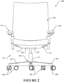
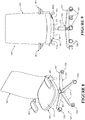
- Figures 1 to 7 show a chair 101 in accordance with a first preferred form of the present invention.
- Figures 8 to 11 show a chair 101' in accordance with a second preferred form of the present invention.
- Both of the chairs may have any one or more of the features described below.
- the primary difference between the first preferred form chair 101 and the second preferred form chair 101' is that the first preferred form chair is a 'mid-back' chair, with a back portion 501 sized and configured to support a seated occupant's back portion up to approximately their shoulder blade region.
- the second preferred form chair 101' is a 'high-back' chair, with the back portion 501' sized and configured to support a seated occupant's back portion up to and including their shoulder region.
- like reference numerals indicate like parts in the figures, with a prime (') indicating the sections that differ.
- Each chair has a supporting frame 102 comprising a base 103 for supporting the chair on a floor surface.
- the base is a castered base 103 having a plurality of radially extending legs 107 extending outwardly from a single central hub. In the form shown, there are five legs. However, it will be appreciated that there may be more or less legs.
- a caster or roller 109 is rotatably mounted at the end of radially-extending leg 107 opposite to the central hub. The casters enable a chair occupant to move the base 103 and thereby the chair along the ground surface.
- the chair may comprise a fixed base that does not provide for rolling movement of the chair on the ground surface.
- a height adjustable column 111 is coupled to the central hub of the base and extends upwardly therefrom.
- the height adjustable column can be any suitable type of pneumatic or gas spring, which enables height adjustment of the chair seat portion 171 and back portion 501, 501' relative to the ground surface.
- a main transom 121 of the supporting frame is coupled to an upper end of the height adjustable column 111, such that height adjustment of the column causes height adjustment of the transom 121 and supported components.
- a seat portion 151 for supporting a seated occupant and a back portion 501, 501' supporting the back of a seated occupant are coupled to the transom 121 via a recline mechanism described below, so that the seat portion 151 and back portion are movable relative to the supporting frame.
- the seat portion 151 and back portion 501 will be described in further detail below.
- the chairs 101, 101' may be provided with or without arm support assemblies 401 to support an occupant's arms.
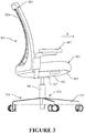
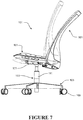
- the back portion 501 , 501' of the chair is reclinable relative to the supporting frame 102 between an upright position ( Figures 3 and 10 ) and a reclined position ( Figure 7 ).
- the chair comprises a recline mechanism coupling the back portion 501, 501' to the seat portion and the transom 121.
- the recline mechanism is configured to lift the seat portion 151 as the back portion 501, 501' reclines.
- the seat portion 151 preferably lifts upwardly and rearwardly and increases in rearward tilt angle, as the back portion 501, 501' is reclined.
- the lifting of the seat portion provides a 'weight-compensated' recline mechanism, meaning more force is required for a heavier seated occupant to recline the back portion than for a lighter seated occupant to do so.
- the seat portion 151 comprises a seat support and a seating surface 171 for supporting a seated occupant.
- the seating surface 171 is selectively moveable in a forward and rearward direction relative to the seat support to selectively adjust seat depth relative to the back portion 501, 501'.
- the seating surface 171 may be fixed to the seat support 161 and not depth adjustable.
- the seating surface 171 is a cushioned and upholstered surface. Alternatively, it may be a compliant slotted seat panel, or a combination of a slotted seat panel and a cushioned and upholstered surface for example.
- three actuators 191a, 191b, 191c are flush-mounted in the underside shell 181, and are provided to enable the occupant to adjust features of the chair by moving the actuators.
- the front actuator 191a on the left hand side of the chair adjusts the recline resistance (described in more detail below)
- the actuator 191b on the right hand side of the chair adjusts the height and depth of the seating surface 171
- the rear actuator 191c on the left hand side of the chair actuates an upright lock 251 to prevent recline of the back portion.
- the chair 101, 101' has a pair of arm assemblies 401 positioned one on either side of the seat assembly 151.
- the arm assemblies 401 are connected to the back portion 501, 501' so that the arm rests move with the back portion as it reclines.
- the arm assemblies 401 could connect to a different part of the chair, such as the seat portion 151 or the supporting frame (e.g. the transom 121).
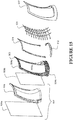
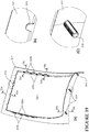
- FIGS 12 to 37 illustrate a preferred form back assembly 501.
- the back assembly 501 comprises a back frame 503 having side frame members 504a and upper 504b and lower 504c frame members defining an opening 503a.
- a support 531 which is described in further detail below, is attached to the frame 503 and suspended across the frame opening 503a.
- a cushion assembly 507 is positioned in front of the frame 503 and against a front surface of the support 531.
- One or more staple-receiving members 511, 512 are fixed to a rear side of the frame 503 for connecting the cushioning portion 507 to the frame 503.
- An aesthetic cover 517 is positioned on a rear side of the back assembly to cover the connections between the frame 503, the cushioning assembly 507, and the staple-receiving member(s) 511, 512.
- a forwardly protruding connecting portion 505 is connected to the lower frame member 504c to connect the back assembly 501 to the recline mechanism 201.
- the connecting portion 505 connects to the back support arm 203 of the recline mechanism described above, enabling the back portion to be reclined relative to the transom.
- the back support arm 203 and the connecting portion 505 of the back frame may be integral.
- the back assembly 501 may be fixedly connected to the transom or seat portion, or may be connected to the transom by way of an alternative mechanism so that recline or movement of the back assembly 501 is the same as or differs from that described above in relation to the recline mechanisms 201, 201'.
- the back frame 503 defines a substantially rectangular opening 503a.
- the support 531 comprises a plurality of spaced apart elongate longitudinally extending straps 533 and a plurality of spaced apart transversely extending straps 535.
- the longitudinal straps 533 and the transverse straps 535 each comprise two opposite end connectors 545 each having an aperture 547.
- the longitudinal and transverse straps connect to the back frame 503 by hooks 561 such that the support 531 is suspended across the aperture 503a, providing a support surface for the cushioning assembly 507.
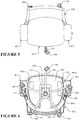
- the back frame 503 and back assembly 501 are preferably forwardly concave about a vertical axis, and at least a lower portion of the back frame and back assembly are preferably forwardly convex about a horizontal transverse axis, to follow the natural curvature of a user's back.
- the cushioning assembly 507 comprises a front upholstery sheet 509a, a cushion 508, and a rear upholstery sheet 509b.
- the cushion 508 is preferably a foam member and may comprise moulded or cut out portions to accommodate part of the back frame 503 and the attachment hooks 561 for the support 531.
- the upholstery sheets could be any suitable type, such as fabric, leather, or synthetic leather for example.
- the front upholstery sheet 509a is glued to a front surface of the cushion, and the rear upholstery sheet 509b is glued to the rear surface of the cushion.
- the cushion 508 is at least as large as the opening 503a defined by the back frame 503, and is preferably sized to substantially cover a front surface of the back frame 503 and the opening 503a.
- the cushion 508 may be slightly larger than the front surface of the back frame 503 so that the peripheral portion of the cushion 508 wraps around the edge of the back frame 503.
- the front upholstery sheet is preferably larger than the front surface of the cushion such that the edges of the front upholstery sheet can be wrapped around the sides of the cushion 508 and partly behind the cushion 508.
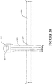
- a rear surface of the back frame 503 comprises a plurality of hollow cylindrical protrusions 515, 516.
- the upper protrusions 515 are shallower than the lower protrusions 516, to enable the upper frame member 504b to be lower profile than the lower frame member 504c.
- the staple-receiving members 511, 512 each comprise a front surface with a plurality of forwardly protruding complementary crush dowels 513, 514 as shown in Figures 17(a) to (c) .
- the crush dowels 513, 514 have an outer diameter that is slightly larger than the inner diameter of the hollow projections 515, 516 on the rear of the back frame.
- FIGS 18(a) and 18(b) illustrate the step of assembling the staple-receiving members 511, 512 to the frame 503.
- the dowels 513, 514 comprise ribs about their periphery. At least some of these ribs are flattened when the dowels 513, 514 are forced into the cylindrical protrusions 515, 516 on the back frame 503, forming a tight friction fit between the staple-receiving members 511, 512 and the frame 503.
- the staple-receiving members 511, 512 and dowels 513, 514 preferably comprise a thermoplastic polymeric material with a lower hardness than the back frame 503.
- the staple-receiving members may be formed of polypropylene, and the frame may be formed of 30% glass fibre reinforced PET.
- the deformation of the dowels 513, 514 is typically a plastic deformation, such that the staple-receiving members 511, 512 cannot be firmly reattached if they are removed.
- the staple-receiving members 511, 512 could be attached to the frame 503 by other means, for example using fasteners, adhesive, or other snap-type connections.
- the frame could receive the staples directly.
- the front upholstery sheet could be fastened to the frame using any suitable means, such as those described above for example.
- the staple-receiving members 511, 512 provide a surface for stapling the cushioning assembly 507 to the back frame 503.
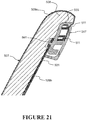
- Figure 21 shows the attachment of the cushioning assembly 507 to an upper portion of the back frame 503.
- the front upholstery sheet 509a wraps around the edges of the cushion 508, and behind the back frame 503 and staple-receiving members 511, 512.
- the front upholstery sheet 509a is then stapled to the rear side of the staple-receiving members 511, 512.
- the staple-receiving members provide a surface that is softer than the back frame 503 for receiving staples.
- the rear upholstery member 509b may also wrap around the edge of the back frame 503 and be stapled to the staple-receiving members 511, 512 together with the front upholstery sheet 509a.
- the cushion 508 and/or the rear upholstery sheet 509b may be glued to the front surface of the back frame 503.
- An aesthetic cover 517 shown in Figure 19 is attached to the rear side of the back frame 503 to cover the stapled portion of the front upholstery sheet 509a, the staple-receiving members 511, 512, and the rear side of the back frame.
- the aesthetic cover 517 comprises an opening 517a that is approximately the same size, or slightly smaller than, the back frame opening 503a so that the support 531 and back upholstery sheet 509b are visible from behind the back portion.
- the opening in the aesthetic cover 517 also allows portions of the cushioning assembly 507 and support 531 to deflect rearwardly beyond the frame 503 and aesthetic cover 517 during support of a user.
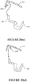
- an upper portion of the aesthetic cover 517 comprises a plurality of upwardly projecting tabs 518.
- the tabs 518 are for engaging with corresponding recess(es) 521 on a front surface of the back frame 503, as shown in Figure 20(a) .
- a lower portion of the aesthetic cover 517 comprises a plurality of forwardly projecting crush dowels 519 as shown in Figures 19(c) and 20(b) .
- Side portions of the aesthetic cover 517 comprise a plurality of outwardly directed tabs 520a and outer projections 520b.
- Corresponding catch features 522 on the side members of the back frame are receivable in the space between the outwardly directed tabs 520a and outer projections 520b.
- a lower portion of the back frame 503 comprises a plurality of hollow cylindrical protrusions 506.
- the crush dowels 519 are similar to those described above with respect to the staple-receiving members 511, 512.
- the aesthetic cover 517 is attached to the back frame 503 by first positioning the upper portion of the aesthetic cover 517 relative to the upper back frame member so that the recess(es) 521 is/are behind the tabs 518 ( Figure 20(a) ), snapping the side catch features 522 between the side tabs 520a and projections 520b ( Figure 20(c) and 20(d) ), then pressing the crush dowels 519 into the respective hollow protrusions 506 on the back frame ( Figure 20(b) ), deforming the crush dowels 519.
- the 'high back' back portion 501' will be formed in the same way as the back portion 501. However, the upper portion of the back frame 503 will have a 'blade' above the opening, which will support the upper end of the cushioning assembly.
- the cushioning assembly may have a pocket or similar to receive the blade to assist with mounting the cushioning assembly to the blade of the frame.
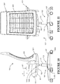
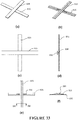
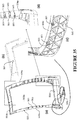
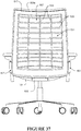
- Figure 37 is a rear view of a preferred form chair showing the support 531 supporting the cushioning assembly member 507 in the back portion 501.
- the support has the appearance of a plurality of individual longitudinal straps 533 overlaid over a plurality of individual transverse straps 535. While a support comprising a plurality of individual straps has aesthetic advantages, such an arrangement presents a number of assembly and performance disadvantages compared to a one-piece moulded support. Individually attaching many separate straps to a frame is more labour intensive and, where the straps are different lengths presents difficulties in ensuring the straps are in the correct order and orientation. In use, parallel straps are susceptible to twisting or to moving relative to each other, losing the aesthetically appealing grid arrangement.
- Figures 22 to 37 show a preferred form moulded support 531 for attaching to the frame 503 to form the support shown in Figure 37 having the appearance of individual straps.
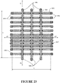
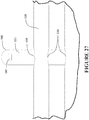
- FIGS 22 to 27 , 31(a) to (f) , and 32(a) and (b) show the support 531 as moulded.
- the moulded support 531 is substantially flat and comprises a plurality of elongate longitudinal straps 533 and a plurality of elongate transverse straps 535.
- the transverse straps 535 form a first layer
- the longitudinal straps 533 overlap with the transverse straps 535 to form a second layer that overlies the first layer.
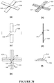
- Integrally moulded joiner members 536 connect the transverse and longitudinal straps 535, 533 and are positioned at the overlapping portions of the straps 533, 535.
- each longitudinal strap is attached to each transverse strap by the joiner members 536.
- the longitudinal and transverse straps 533, 535 preferably have substantially the same cross-sectional width and thickness, at least in the unnecked regions.
- the straps may have a width WUT, WUL in the unnecked regions of 12 mm, and may have a depth of about 1 mm along their necked and unnecked regions.
- the longitudinal straps may have different cross-sectional dimensions to the transverse straps if different properties are desired in the longitudinal direction to the transverse direction, or if a combination or differently sized straps are desired for aesthetic reasons.
- the lengths of the longitudinal straps 533 may vary to fit a frame 503 with non-parallel upper and lower frame members, or to accommodate differing degrees of curvature in the longitudinal straps 533 in the assembled form.
- the lengths of the transverse straps 535 may vary for the same reasons with respect to the side members of the frame.
- the transverse straps 535 and the longitudinal straps 533 may be evenly spaced, or the spacing between adjacent straps may vary. In the form shown, the transverse straps are spaced more sparsely towards the upper portion of the support 531 and are spaced closer together in the portion of the support that corresponds to the lumbar portion of the chair back portion. The support will be less compliant where the straps are closer together, to provide a greater level of support.
- the joiner members 536 are preferably elongate in the transverse direction.
- the joiner members measure 18.5 mm in the transverse strap direction, 1.0 mm in the longitudinal strap direction, and 2.0 mm deep (to form a gap between the straps of 2.0 mm).
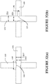
- the joiner members 536 project from a front face of the transverse straps 535 and connect to a rear face of the longitudinal straps 533.
- Both the transverse and longitudinal straps are necked on either side of each joiner members 536 by way or notches or recesses in the sides of the straps.
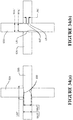
- the transverse straps 535 comprise necked regions 539 that comprise recesses extending substantially the length of the joiner members 536.
- the necked regions may have a length LNT of 17.9 mm, and the width WNT of the transverse strap between the recesses may be 10.0 mm, as shown in Figure 32(a) .
- the longitudinal straps 533 comprise necked regions 537 that, in the form shown, comprise notches.
- the necked regions as moulded are longer than the thickness of the joiners 536 but, as moulded, are smaller than the width of the respective transverse strap 535.
- the necking 539 on the transverse straps 535 is shallower than the necking 537 on the longitudinal straps 533.
- the width WNL of the necked regions between the notches may be 9.4 mm, and the notches may each have a length LNL of about 4.1 mm.
- the dimensions of the necked areas are selected to allow the strap to have substantially parallel sides after it has been relaxed post-strain orientation, as described in further detail below.
- the configuration shown in Figures 32(a) and 32(b) is one example configuration for straps that will be stretched to 450% of their as-moulded lengths to achieve strain orientation.
- the ratio of the two width dimensions will increase or decrease depending on the intended stretching percentage.
- Figure 34 is a view similar to Figure 32 but showing alternative exemplary dimensions of one of the neck areas.
- the dimensions LNT', WUT', WNT', WUL', and WNL' are the same as the respective dimensions LNT, WUT, WNT, WUL, and WNL described with reference to Figure 32 .
- LNL' is a shorter dimension of 3.5 mm compared to the 4.1 mm of LNL of Figure 32 .
- This version has radiuses LR of about 1.25 mm in the region where the necked area 537 meets the straight sides of the longitudinal strap 533. The larger radiuses further assist with obtaining substantially parallel sides in the strap 533 after the strap has been relaxed post-strain orientation.
- each strap has a main body depth of about 1.5 mm along the necked and unnecked regions, and the elongate ribs extending along the straps may each have an additional depth of about 0.5 mm.
- the main body depth of each strap, excluding the elongate rib, will be about 1.0 mm.
- the same principle applies to the necked area on the longitudinal straps with the dimensions shown being intended for the strap to have substantially parallel sides after relaxing following from stretching to 450%.
- the selected ratio for the longitudinal strap for an elongation to 450% is 0.783 (9.4/12).
- LNT necked region length
- the elongate ribs shown on the front surfaces of the straps in Figure 30 aid stretching and strain orientation, and aid moulding material flow where the joiner meets the straps.
- joiner members may vary without departing from the scope of this aspect of the invention.
- the support 531 can be moulded using any suitable method known to a person skilled in the art.
- the support could be injection moulded using the method described in our PCT publication number WO 2009/126051 .
- the support could alternatively be moulded using more conventional moulding parameters.
- the support 531 is moulded from one or more materials that are suitable for strain orientation.
- suitable materials include some of the HYTREL materials available from Du Pont.
- the polymer chains in the material are relatively random. By stretching the article, the polymer chains become relatively aligned. That phenomenon is strain orientation. Strain orientation changes the material properties. Typically, the material becomes stronger and more elastic; that is the elastic limit is increased in comparison to the as-formed material. Additionally, the article generally lengthens in the direction of stretching and reduces in cross-section.
- the material is a thermoplastic polyester elastomer.
- the thermoplastic polyester elastomer is a block copolymer comprising a hard (crystalline) segment of polybutylene terephthalate and a soft (amorphous) segment based on long chain polyether glycols.
- the thermoplastic polyester elastomer resin is selected such that the article formed by the moulding method, once fully cured and prior to strain orientation, has a hardness in the range of about 30D to about 55D when tested in accordance with ASTM D2240.
- the thermoplastic polyester elastomer resin is selected such that the article has a hardness in the range of about 30D to about 46D, more preferably in the range of about 35D to about 45D, preferably in the range of about 36D to about 44D, more preferably in the range of about 37D to about 43D, more preferably in the range of about 38D to about 42D, more preferably in the range of about 39D to about 41D, most preferably about 40D.
- the thermoplastic polyester resin is preferably one of HYTREL 4069, HYTREL 4556, HYTREL 5526, HYTREL 5556, HYTREL 3078. Most preferably, the resin is HYTREL 4069.
- the resin may additionally include stabilisers and/or additives to achieve desired properties, for example to improve its resistance to UV light, fire, heat aging, moisture, and/or to make the resin a suitable colour.
- the moulded article of the present invention could be formed from any other resins having suitable properties.
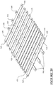
- the moulded support of Figures 22 to 27 is then stretched in both directions as represented by arrows SL, ST to form the elongated support 531 shown in Figures 28 to 30 and 37 .
- the straps 533, 535 are each stretched SL, ST in their longitudinal direction to lengthen the straps.
- This elongation causes strain orientation of the material in the straps, as well as in the joiner members 536.
- the regions 537, 539 are the widest parts of the straps.
- the sides of the straps relax to be substantially parallel along their lengths, including in regions 537, 539.
- the dimensions of the stretched support during this step are greater than the dimensions of the frame that the support is to be attached to. That is, the longitudinal straps 533 are stretched SL to a length greater than the distance between the upper and lower portions 504b, 504c of the frame, and the transverse straps 535 are stretched ST to a length greater than the dimensions between the frame side members 504a.
- the stretched length of the straps is between about 4 and about 5 times the as-moulded dimension of the straps, and preferably about 4.5 times the as-moulded dimension.
- Each strap is preferably stretched by proportionally the same amount. That is, the straps might each be stretched to 450% of their initial moulded length, for example. That ensures that any straps that are moulded to have the same cross sectional dimensions but different lengths, will also have substantially the same cross sectional dimensions in their stretched form, and the proportional difference in length between the straps will be maintained.
- the elongated straps will therefore also have the same strain orientation and properties despite their differing lengths. Alternatively, if different properties are desired for different straps, for example if more compliance is required at different points in the support, the straps may be elongated to different extents.
- the straps may be elongated one at a time.
- all of the longitudinal straps 533 may be elongated together, followed by all of the transverse straps, or conversely all of the transverse straps 535 may be elongated together, followed by all of the longitudinal straps 533.
- all of the longitudinal and transverse straps may be elongated sim ultaneously.
- FIGs 28 to 30 and 33 show the support 531 in the relaxed state. Due to the alignment of the material in the straps, the length of the relaxed straps is longer than the initial length of the straps in their moulded form. In the relaxed state, the dimensions of the stretched support during this step are smaller than the dimensions of the frame that the support is to be attached to. That is, the longitudinal straps 533 are shorter than the length between the upper and lower frame members, and the transverse straps 535 are shorter than the dimensions between the frame side members.
- the sides of the transverse straps 535 are parallel, and the sides of at least the portions of the longitudinal straps 533 that are visible from the transverse strap side of the support, are parallel.
- the sides of the longitudinal straps are parallel along their entire lengths.
- the width of both the necked portions of the straps and the unnecked portions of the straps decrease.
- the reduction in width is greater in the unnecked portions due to greater strain orientation. This compensates for the smaller reduction in width of the necked portions such that the width of the necked portions is substantially the same as the width of the unnecked portions post-strain orientation.
- the necking 539 on the transverse straps 535 is has a more gentle curvature than the necking 537 on the longitudinal straps 533. It is desirable that the joiner members 536 are oriented so that the necking in the longitudinal direction of the joiner members 536 is on the transverse straps 535 that form the rearmost layer of the support 531. This is because after strain orientation, the edges of the straps may not be perfectly parallel in the necked regions 537, 539 adjacent the joiner members 536. Any difference in the width of the strain oriented straps in the necked regions tends to be less pronounced with the more gently-curved necked regions.
- the straps with the more tightly curved necked regions are the straps that form the front layer of the support, such that any irregularities in the widths of those straps at the necked regions are obscured by the rearmost straps 535 from behind, and by the cushioning assembly from the front.
- the support 531 is uncovered to provide an exposed occupant supporting surface in use and is visible from the front portion of the chair
- the support could effectively be reversed so that the transverse straps 535 with the more gentle curvature necking are positioned in front of the longitudinal straps 533.
- the longitudinal straps may be positioned in front of the transverse straps, but the joiner members 536 may be reoriented so they are elongate in the longitudinal direction, and the longitudinal straps may be provided with the more gentle curvature necking.
- the post-stretching relaxation lengths of the straps RL, RT is between about 1.5 and about 2.7 times the as-moulded dimension, preferably about 2.1 times the respective as-moulded strap lengths IL, IT.
- both the transverse and longitudinal straps will be longer than prior to strain orientation, and will have a smaller cross-section, both in a width and depth direction.
- the depth of the straps may reduce from 1.5 mm to 1.0 mm. This is evident from the figures by the increased distance between the transverse and longitudinal straps. That is, the lengths of the SL, ST straps will be greater than the initial lengths IL, IT, and the strap cross-sections will be smaller than the initial strap cross-sections.
- the post-stretching relaxation lengths RL, RT will be smaller than the lengths of the stretched SL, ST straps, but greater than the initial lengths IL, IT.
- the post-stretching relaxation strap cross-sections will be between the initial strap cross-sections and the stretched strap cross-sections.
- the as-moulded length of the longest longitudinal strap 533 is about 255 mm. That is stretched out to 1147.5 mm, but could be stretched any suitable amount relative to its starting length, such as between about 4x and 9x its starting length.
- the as-moulded length of the longest transverse strap 535 is about 210 mm. That is stretched out to 945 mm, but could be stretched any suitable amount relative to its starting length, such as between about 4x and 9x its starting length.
- the longest longitudinal strap is then relaxed to 519 mm, and the longest transverse strap is relaxed to 426 mm. The relaxed lengths (and therefore the initial moulded lengths and the extent of stretching) will vary for different frame configurations or different desired final product tensions.
- the sizes of the joiner members 536 also change due to the strain orientation that occurs when stretching the longitudinal straps 533 and the elongate straps 535.
- the joiner members 536 may initially measure 18.5 mm long, 1.0 mm wide, and 2.0 mm deep (the dimension between straps), and may measure 28.5 mm long, 0.8 mm wide, and 1.8 mm deep after elongation. These width and depth measurements are taken through the centre of the joiner members. These are values at the centre of the joiner members, as the joiner members will have radii where they intersect with the transverse and longitudinal straps for moulding and strength purposes.
- the joiner members 536 are strain oriented in both the longitudinal and transverse directions of the support, as a result of stretching both the longitudinal straps 533 and the transverse straps 535.
- the reduction in width of the joiner members from 1.0 mm to 0.8 mm is less than it would be if the joiner members were not strain oriented in a direction across the width of the joiner members a result of stretching the longitudinal straps 533.
- joiner members are shown as being longer than the width of the longitudinal straps, that is primarily for moulding purposes.
- the joiner members could be any other suitable shape or size.
- Each of the transverse and longitudinal straps comprises an attachment portion 545 at each of its ends.
- the attachment portions 545 are integrally formed as part of the moulding process, and are used to attach the cover to the frame 503.
- the attachment portion 545 comprises a portion of increased thickness having an aperture 547.
- the attachment portions are generally not elongated to any great extent, so strain orientation does not occur or does not occur to a great extent in the regions of the side attachment features and the material in those portions remains substantially unaligned.
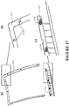
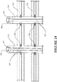
- Figures 35(a) to 35(d) shows a preferred attachment of the support 531 to the back frame 503.
- the back frame is provided with a plurality of hooks 561 that are integrally moulded as part of the frame.
- the hooks are spaced apart around the perimeter of the frame and each define a recess between the hook and the frame.
- the hooks are provided on a front face of the top frame member 504b, on a front face of the side frame members 504a, and in a rear face of the bottom frame member 504c.
- the hooks face outwardly from a centre of the back portion, so tension in the support 531 keeps the support engaged with the hooks in use.
- At least some of the hooks are provided in recesses 563 in the frame, with the recesses sized to receive the integral connectors 545 on the straps.
- the top and side hooks shown in Figure 36a may be provided in recesses, or may be surface-mounted as shown.
- the support can be mounted to the back frame by inserting the hooks 561 through the apertures 547 that are provided on the attachment portions 545.
- the spacing of the hooks 561 on the side portions 504a of the frame corresponds to the spacing of the transverse straps 535.
- the spacing of the hooks on the upper and lower frame members 504b, 504c corresponds to the spacing of the longitudinal straps 533.
- the spacing of the hooks may be even for evenly spaced straps, or may vary if the spacing of straps varies, to provide greater support in one portion of the support. For example, in the form shown, the hooks on the side portions of the frame are more closely spaced near the lumbar region of the back portion, to provide greater support to the lumbar region of a user.
- each of the transverse straps 535 is hooked to the frame.
- the straps are then stretched and the opposite ends of each strap are hooked to the frame. This process is then repeated for the longitudinal straps 533 which are positioned in front of the transverse straps.
- the support may be stretched again to or beyond its final dimensions and then connected to the frame.
- the support could be relaxed onto the frame after expanding the support to strain orientate the straps.
- the attachment features could all be provided on a front face of the frame, on a rear face of the frame, or on a combination thereof. Rather than being hooks, the attachment features could instead be projections. However, hooks are preferred to provide a more positive engagement.
- the attachment features on the frame may primarily serve a locating function.
- the support could additionally be secured to the frame by any suitable means, such as adhesive, fasteners, or welding the support to the frame for example.
- the longitudinally extending straps 533 extend between upper and lower transverse back frame members (or between front and rear seat frame members in the case of a seat), and the transverse members 535 substantially extend between side frame members.
- the end result in at least preferred embodiments is a compliant suspended support surface that is pliable, and has good creep resistance and tensile strength.
- the straps 533, 535 are substantially flat members.
- the straps or the moulded support 531 may have a curved profile formed as part of the moulding process.
- at least part of the article may have a curved side profile and/or a curved top profile that is formed as part of the moulding process.
- the contour of the support may be changed by attachment of the support to a contoured frame.
- the flat moulded support 531 has a forwardly convex form when it has been attached to the forwardly convex back frame.
- the moulded support 535 has been described above in reference to a support for the back portion of a chair.
- the moulded support may have other applications.
- the moulded article may be a support surface for a chair, for example.
- the seat or back frame comprises an opening that is at least partly bounded by frame members, and the method comprises supporting the moulded article from the frame with part of the moulded article extending across the opening, to form a compliant suspended support surface.
- the thickness of the straps 533, 535 may be greater than mentioned above; for example about twice the thickness mentioned above.
- the widths of the elongate straps 533, 535 could be greater than mentioned above; for example about twice the widths mentioned above.
- the moulded article may be any other suitable type of article.
- the articles could have application as or in: resistance members in exercise equipment; contact sport helmets; helmet and hat liners; harnesses for backpacks, climbing, safety, paraponting, bungee jumping; support surfaces for baby products including car seats, bouncy beds, baby buggies, cots; trampolines such as springs, mats, minitramps, fire trampolines; other furniture such as dental chairs, aeroplane seating, stadium seating, outdoor furniture; bedding, such as mattress replacements, mattress support surfaces, or pillows; automotive seating, soft tailgates, canopies; hammocks; wake board, snow board, and/or ski bindings; bicycle seats; luggage stowage in transport; hitting surfaces of racquets for sports such as tennis, squash, badminton; wetsuits such as flexible inserts; yachting, such as a catamaran trampoline surface.
- the elongate straps 533, 535 could have significantly different cross-sectional dimensions and lengths from those mentioned above.
- the extent to which the straps are elongated may also vary. For example, for higher load capacities, the members could have larger cross-sections.
- the moulded article is described as being a support for the back of a reclining office chair.
- the moulded article can readily be incorporated into different types of chairs, such as dental chairs, meeting seats, vehicle seats, stadium seats, theatre seats, aircraft or other vehicle seats for example.
- the supporting frame could be modified accordingly, so as to be fixed to the ground or a wall panel for example for a theatre seat.
- the straps 533, 535 of the back portion could be separate extruded straps that are strain oriented and connected to the back frame to provide support for the cushioning assembly 507.
- the moulded integral support 531 is preferred, as the joiner members 535 link the straps 533, 535 to each other, and prevent the straps from moving significantly relative to each other. If separate straps are used, they would need to be separately tethered to each other to prevent excessive independent movement of the straps, such as via adhesive, welding, or the like. Therefore, the preferred form moulded support described above provides significant manufacturing efficiencies over this alternative form.
- the moulded support 531 is described as being used to support a cushioning assembly on a frame. Instead, the moulded support 531 could form the body-contacting surface that supports the seated occupant.
Claims (14)
- Un article moulé par injection (531) convenant à l'orientation de la traction, l'article comprenant :une pluralité de premiers rubans moulés allongés (535) formés dans une première couche ;une pluralité de deuxièmes rubans moulés allongés (533) formés dans une deuxième couche, pour que certains des premiers rubans allongés au moins (535) se chevauchent au moins à certains des deuxièmes rubans allongés (533) ; etune pluralité d'éléments de menuisier moulés (536) qui sont intégralement moulés par injection avec les premiers rubans allongés (535) et avec les deuxièmes rubans allongés (533), et qui connectent entre les premiers rubans allongés (535) et les deuxièmes rubans allongés (533) dans les zones où les premiers rubans allongés (535) et les deuxièmes rubans allongés (533) se chevauchent.
- Un article moulé par injection selon la revendication 1, dans lequel au moins une portion des premiers rubans allongés (535), au moins une portion des deuxièmes rubans allongés (533) et au moins une portion des éléments du menuisier (536) conviennent à l'orientation de la traction, et de préférence dans laquelle sensiblement l'ensemble des premiers rubans allongés (535), sensiblement l'ensemble des deuxièmes rubans allongés (533), et sensiblement l'ensemble des éléments du menuisier (536) conviennent à l'orientation de la traction.
- Un article moulé par injection selon la revendication 1 ou 2, dans lequel les premiers rubans allongés (535) comprennent les zones du cou (539) adjacentes aux éléments du menuisier (536), pour compenser une réduction de l'orientation de la traction en raison de la matière supplémentaire des éléments du menuisier, et de préférence dans lequel les zones du cou (539) sont formées par les encoches ou les évidements s'entendant sur les côtés des premiers rubans allongés, et de préférence dans lequel les encoches et les évidements sont configurés pour que l'orientation précédant la traction, les côtés des premiers rubans allongés (535) soient sensiblement parallèles le long de toutes leurs longueurs sensiblement.
- Un article moulé par injection selon l'une quelconque des revendications 1 à 3, dans lequel les deuxièmes rubans allongés (533) comprennent des zones du cou (537) adjacentes aux éléments du menuisier (536), pour compenser une réduction de l'orientation de la traction en raison de la matière supplémentaire des éléments du menuisier, et de préférence dans lequel les zone du cou (537) sont formées par des encoches ou des évidements s'étendant sur les côtés des deuxièmes rubans, et de préférence dans lequel les encoches ou les évidements sont configurés pour que l'orientation précédant la traction, les côtés des deuxièmes rubans allongés (533) soient sensiblement parallèles le long de toutes leurs longueurs sensiblement.
- Un article moulé par injection selon l'une quelconque des revendications de 1 à 4, dans lequel les premiers rubans allongés (533) comprennent des rubans s'étendant généralement longitudinalement, et dans lequel les deuxièmes rubans allongés (535) comprennent des rubans s'étendant généralement transversalement, et / ou dans lequel l'article moulé par injection (531) est sensiblement plat.
- Un article moulé par injection selon l'une quelconque des revendications de 1 à 5, dans lequel l'article moulé par injection est moulé à partir d'une résine comprenant un élastomère de polyester thermoplastique, et de préférence dans lequel l'élastomère polyester thermoplastique comprend un copolymère en bloc de polyalkylène-téréphtalate de polyéther, et de préférence dans lequel l'élastomère de polyester thermoplastique est un copolymère en bloc de polyalkylène-téréphtalate de polyéther, et de préférence dans lequel la résine est sélectionnée pour que l'article moulé par injection ait une dureté dans la gamme de 30D à 55D lorsque testé conformément à la norme ASTM D2240.
- Un article moulé par injection selon l'une quelconque des revendications 1 à 6, dans lequel au moins une partie de l'article (531) peut être étirée à au moins 400 % d'une dimension initiale sans défaillance, pour que l'orientation de la traction se produise.
- Une méthode d'assemblage d'un support, comprenant :la fourniture d'un cadre (503) ;la fourniture d'un article moulé par injection (531) selon l'une des revendications de 1 à 7, dans lequel une partie de l'article moulé par injection a une dimension moulée tel que (IL, IT) inférieure à la dimension correspondante du cadre (503) ;l'étirement (SL, ST) au moins ladite partie de l'article moulé par injection (531) pour obtenir une dimension étirée supérieure à la dimension correspondante du cadre (531) pour que l'orientation de la traction d'une portion au moins des premiers rubans allongés (535) et une portion au moins des deuxièmes rubans allongés (533) se produise ;le relâchement de ladite partie de l'article au moins (531) pour obtenir une dimension précédant le relâchement (RL, TL) entre la dimension moulée tel que (IL, IT) et la dimension étirée ;et le support de l'article (531) à partir du cadre (503).
- Une méthode selon la revendication 8, dans laquelle le cadre (503) comprend une ouverture (503a) qui est au moins en partie liée par les éléments du cadre (504a, 504b, 504c), et la méthode comprend le support de l'article (531) à partir du cadre (503) avec une partie de l'article s'étendant à travers l'ouverture (503a), pour former une surface de soutien suspendue conforme.
- Une méthode selon la revendication 8 ou 9, dans laquelle les premiers rubans allongés (535) comprennent des rubans s'étendant généralement longitudinalement, et comprennent des rubans s'étendant généralement transversalement, et de préférence dans laquelle la méthode comprend l'étirement et le relâchement des rubans s'étendant généralement longitudinalement (535) avant d'étirer et de relâcher les rubans s'étendant généralement transversalement (533) ou comprend l'étirement et le relâchement des rubans s'étendant généralement transversalement (533) avant d'étirer et de relâcher les rubans s'étirant généralement longitudinalement (535) ou comprend l'étirement et le relâchement des rubans s'étendant généralement transversalement (533) parallèlement à l'étirement et au relâchement des rubans s'étendant généralement longitudinalement (535).
- Une méthode selon l'une quelconque des revendications 8 à 10 dans laquelle l'étape de l'étirement d'une partie au moins de l'article (531) entraîne l'étirement des éléments du menuisier (536) pour que l'orientation de la traction des éléments du menuisier (536) se produise, et de préférence dans laquelle les éléments du menuisier (536) soient orientés vers la traction à la fois dans la direction longitudinale et transversale.
- Une méthode selon l'une quelconque des revendications 8 à 11, dans laquelle les premiers rubans allongés (535) comprennent des zones du cou (539) adjacentes aux éléments du menuisier (536) pour compenser une réduction de l'orientation de la traction en raison de la matière supplémentaire des éléments du menuisier, et de préférence dans laquelle les zones du cou (539) sont formées par des encoches ou des évidements s'étendant sur les côtés des premiers rubans allongés (535), dans laquelle les côtés des premiers rubans allongés (535) dans l'article relâché sont sensiblement parallèles le long de toutes leurs longueurs sensiblement.
- Une méthode selon l'une quelconque des revendications 8 à 12, dans laquelle les deuxièmes rubans allongés (533) comprennent des zones du cou (537) adjacentes aux éléments du menuisier (536) pour compenser la réduction de l'orientation de la traction en raison de la matière supplémentaire des éléments du menuisier, et de préférence dans laquelle les zones du cou (537) sont formées par des encoches ou des évidements qui s'étendent généralement sur les côtés des deuxièmes rubans allongés (533) adjacents aux éléments du menuisier, dans laquelle les côtés des deuxièmes rubans allongés (533) dans l'article relâché sont sensiblement parallèles le long de toutes leurs longueurs sensiblement.
- Une portion arrière (501, 501') pour une portion de chaise ou de siège (151) pour une chaise lorsqu'assemblée en utilisant une méthode de l'une quelconque des revendications de 8 à 13.
Applications Claiming Priority (2)
| Application Number | Priority Date | Filing Date | Title |
|---|---|---|---|
| US201261715044P | 2012-10-17 | 2012-10-17 | |
| PCT/IB2013/059247 WO2014060910A1 (fr) | 2012-10-17 | 2013-10-10 | Chaise et supports |
Publications (3)
| Publication Number | Publication Date |
|---|---|
| EP2908698A1 EP2908698A1 (fr) | 2015-08-26 |
| EP2908698A4 EP2908698A4 (fr) | 2016-10-05 |
| EP2908698B1 true EP2908698B1 (fr) | 2017-09-06 |
Family
ID=50487629
Family Applications (1)
| Application Number | Title | Priority Date | Filing Date |
|---|---|---|---|
| EP13846395.5A Active EP2908698B1 (fr) | 2012-10-17 | 2013-10-10 | Chaise et supports |
Country Status (12)
| Country | Link |
|---|---|
| US (1) | US10070727B2 (fr) |
| EP (1) | EP2908698B1 (fr) |
| JP (1) | JP6403167B2 (fr) |
| CN (1) | CN104869868B (fr) |
| AU (1) | AU2013333544B2 (fr) |
| CA (1) | CA2885577C (fr) |
| HK (1) | HK1208318A1 (fr) |
| MX (1) | MX354420B (fr) |
| NZ (1) | NZ628904A (fr) |
| RU (1) | RU2649381C2 (fr) |
| SG (1) | SG11201503010WA (fr) |
| WO (1) | WO2014060910A1 (fr) |
Families Citing this family (14)
| Publication number | Priority date | Publication date | Assignee | Title |
|---|---|---|---|---|
| MX2011006225A (es) * | 2008-12-12 | 2011-06-28 | Formway Furniture Ltd | Una silla, un soporte y componentes. |
| JP6771278B2 (ja) * | 2015-09-09 | 2020-10-21 | 株式会社エルゴジャパン | 下部仕切り板 |
| US10463153B2 (en) | 2016-06-09 | 2019-11-05 | Steelcase Inc. | Seating arrangement |
| CN109480521A (zh) * | 2017-09-10 | 2019-03-19 | 浙江玛拉蒂智能家具科技有限公司 | 一种坐垫大小调节机构及座椅 |
| DE202018100450U1 (de) * | 2018-01-26 | 2019-04-29 | König + Neurath AG | Sitzmöbel, insbesondere Bürostuhl |
| CN109009717B (zh) * | 2018-08-01 | 2020-01-14 | 浙江工贸职业技术学院 | 一种新型轮椅 |
| CN109239410B (zh) * | 2018-10-13 | 2021-03-26 | 新昌县钕儒农业科技有限公司 | 无源带电显示装置 |
| US10870489B2 (en) * | 2019-05-24 | 2020-12-22 | B/E Aerospace, Inc. | Position adjustable armrest assemblies for passenger seats |
| US11690457B2 (en) * | 2020-02-04 | 2023-07-04 | Hni Technologies Inc. | Chair with flexible internal support |
| US20230284780A1 (en) * | 2022-03-08 | 2023-09-14 | Teng-Jen Yang | One-Piece Chair Backs and Chairs Having the Same |
| WO2023234807A1 (fr) * | 2022-06-01 | 2023-12-07 | Амир ФАТКУЛЛИН | Fauteuil |
| WO2023239262A2 (fr) * | 2022-06-10 | 2023-12-14 | Амир ФАТКУЛЛИН | Soutien lombaire ajustable |
| WO2024010494A1 (fr) * | 2022-07-21 | 2024-01-11 | Амир ФАТКУЛЛИН | Fauteuil |
| WO2024014990A1 (fr) * | 2022-07-25 | 2024-01-18 | Амир Анварович ФАТКУЛЛИН | Fauteuil |
Family Cites Families (25)
| Publication number | Priority date | Publication date | Assignee | Title |
|---|---|---|---|---|
| US3242628A (en) * | 1961-06-15 | 1966-03-29 | Chicago Metallic Sash Co | Suspended ceiling construction and runner therefor |
| US3554853A (en) * | 1967-11-02 | 1971-01-12 | Plastic Textile Access Ltd | Extruded plastic net made of non-cylindrical strands oriented at points remote from bonded areas |
| US3777432A (en) * | 1972-09-18 | 1973-12-11 | Lightolier Inc | Collapsibly joined louver grid |
| US3840269A (en) * | 1973-05-23 | 1974-10-08 | Northern Fibre Co | Lattice reinforced foam rubber seat bun and method of molding same |
| US4060950A (en) * | 1976-12-08 | 1977-12-06 | National Gypsum Company | Concealed clip for hollow strips |
| GB1595331A (en) * | 1977-07-02 | 1981-08-12 | Gilbert M | Mesh structures incorporating orientated plastics components |
| US4210814A (en) * | 1978-01-09 | 1980-07-01 | Jersey Nuclear-Avco Isotopes, Inc. | Control of pyrophoricity in deposits produced by electron beam evaporation of uranium |
| IT224262Z2 (it) * | 1991-09-10 | 1996-03-14 | Cofemo Spa | Supporto ad altezza regolabile per lo schienale di sedie |
| JPH0720677B2 (ja) | 1992-06-18 | 1995-03-08 | 有限会社大三金型製作所 | プラスチック製網体及びその製造方法 |
| NL1007000C2 (nl) * | 1997-09-11 | 1999-03-12 | Dsm Nv | Werkwijze voor de produktie van artikelen met een aangename aanrakingssensatie. |
| US6029962A (en) | 1997-10-24 | 2000-02-29 | Retama Technology Corporation | Shock absorbing component and construction method |
| JP2002119366A (ja) | 2000-10-16 | 2002-04-23 | Kokuyo Co Ltd | 椅 子 |
| US7441758B2 (en) | 2004-06-17 | 2008-10-28 | Illinois Tool Works Inc. | Load bearing surface |
| US7740321B2 (en) | 2006-05-12 | 2010-06-22 | Herman Miller, Inc. | Suspended pixelated seating structure |
| JP5301446B2 (ja) | 2006-10-04 | 2013-09-25 | フォームウェイ ファーニチャー リミテッド | 椅子 |
| US7922248B2 (en) | 2007-01-29 | 2011-04-12 | Herman Miller, Inc. | Seating structure and methods for the use thereof |
| JP4068126B2 (ja) | 2007-02-01 | 2008-03-26 | タキロン株式会社 | 圧縮配向成形体 |
| CN101319496A (zh) * | 2007-06-06 | 2008-12-10 | 徐益鑫 | 注塑圈接格栅 |
| US20090140568A1 (en) | 2007-10-25 | 2009-06-04 | Eric Ping Pang Chan | Body support structure |
| CN101980841B (zh) | 2008-04-08 | 2013-07-17 | 佛姆维家具有限公司 | 注射模制方法 |
| US20100133893A1 (en) | 2008-05-23 | 2010-06-03 | William Raftery | Chair having elastic bands for support surfaces and device for securing the bands to the chair |
| EP2326216B1 (fr) | 2008-06-04 | 2012-10-24 | Herman Miller, Inc. | Siège suspendu |
| MX2011006225A (es) | 2008-12-12 | 2011-06-28 | Formway Furniture Ltd | Una silla, un soporte y componentes. |
| DE102010015866B4 (de) * | 2010-03-09 | 2022-01-20 | Kinnarps Ab | Stuhl |
| RU101623U1 (ru) * | 2010-07-28 | 2011-01-27 | Игорь Владимирович Митюков | Кресло |
-
2013
- 2013-10-10 US US14/430,496 patent/US10070727B2/en active Active
- 2013-10-10 CN CN201380066160.XA patent/CN104869868B/zh not_active Expired - Fee Related
- 2013-10-10 CA CA2885577A patent/CA2885577C/fr active Active
- 2013-10-10 RU RU2015112033A patent/RU2649381C2/ru not_active IP Right Cessation
- 2013-10-10 JP JP2015537387A patent/JP6403167B2/ja active Active
- 2013-10-10 NZ NZ628904A patent/NZ628904A/en unknown
- 2013-10-10 WO PCT/IB2013/059247 patent/WO2014060910A1/fr active Application Filing
- 2013-10-10 MX MX2015004856A patent/MX354420B/es active IP Right Grant
- 2013-10-10 SG SG11201503010WA patent/SG11201503010WA/en unknown
- 2013-10-10 AU AU2013333544A patent/AU2013333544B2/en active Active
- 2013-10-10 EP EP13846395.5A patent/EP2908698B1/fr active Active
-
2015
- 2015-09-14 HK HK15108986.2A patent/HK1208318A1/xx unknown
Non-Patent Citations (1)
| Title |
|---|
| None * |
Also Published As
| Publication number | Publication date |
|---|---|
| EP2908698A1 (fr) | 2015-08-26 |
| CN104869868A (zh) | 2015-08-26 |
| CA2885577C (fr) | 2020-04-14 |
| EP2908698A4 (fr) | 2016-10-05 |
| CN104869868B (zh) | 2018-02-13 |
| MX354420B (es) | 2018-03-02 |
| AU2013333544B2 (en) | 2017-08-17 |
| NZ628904A (en) | 2016-08-26 |
| RU2015112033A (ru) | 2016-12-10 |
| AU2013333544A1 (en) | 2015-04-23 |
| MX2015004856A (es) | 2015-07-21 |
| US20150250319A1 (en) | 2015-09-10 |
| JP6403167B2 (ja) | 2018-10-10 |
| CA2885577A1 (fr) | 2014-04-24 |
| US10070727B2 (en) | 2018-09-11 |
| JP2015532163A (ja) | 2015-11-09 |
| WO2014060910A1 (fr) | 2014-04-24 |
| RU2649381C2 (ru) | 2018-04-02 |
| SG11201503010WA (en) | 2015-05-28 |
| HK1208318A1 (en) | 2016-03-04 |
Similar Documents
| Publication | Publication Date | Title |
|---|---|---|
| EP2908698B1 (fr) | Chaise et supports | |
| US11805914B2 (en) | Back support for a chair | |
| EP2068677B1 (fr) | Chaise | |
| US11786039B2 (en) | Body support assembly and methods for the use and assembly thereof | |
| CA2750749C (fr) | Surface confortable pour siege | |
| US9326613B2 (en) | Upholstered seat with flexible pelvic support | |
| EP0857443B1 (fr) | Ensemble de support pour chaise | |
| EP2579745B1 (fr) | Article de mobilier |
Legal Events
| Date | Code | Title | Description |
|---|---|---|---|
| PUAI | Public reference made under article 153(3) epc to a published international application that has entered the european phase |
Free format text: ORIGINAL CODE: 0009012 |
|
| 17P | Request for examination filed |
Effective date: 20150317 |
|
| AK | Designated contracting states |
Kind code of ref document: A1 Designated state(s): AL AT BE BG CH CY CZ DE DK EE ES FI FR GB GR HR HU IE IS IT LI LT LU LV MC MK MT NL NO PL PT RO RS SE SI SK SM TR |
|
| AX | Request for extension of the european patent |
Extension state: BA ME |
|
| DAX | Request for extension of the european patent (deleted) | ||
| RIC1 | Information provided on ipc code assigned before grant |
Ipc: A47C 7/36 20060101AFI20160420BHEP |
|
| RA4 | Supplementary search report drawn up and despatched (corrected) |
Effective date: 20160906 |
|
| RIC1 | Information provided on ipc code assigned before grant |
Ipc: A47C 7/36 20060101AFI20160831BHEP |
|
| GRAP | Despatch of communication of intention to grant a patent |
Free format text: ORIGINAL CODE: EPIDOSNIGR1 |
|
| STAA | Information on the status of an ep patent application or granted ep patent |
Free format text: STATUS: GRANT OF PATENT IS INTENDED |
|
| INTG | Intention to grant announced |
Effective date: 20170510 |
|
| GRAS | Grant fee paid |
Free format text: ORIGINAL CODE: EPIDOSNIGR3 |
|
| GRAA | (expected) grant |
Free format text: ORIGINAL CODE: 0009210 |
|
| STAA | Information on the status of an ep patent application or granted ep patent |
Free format text: STATUS: THE PATENT HAS BEEN GRANTED |
|
| AK | Designated contracting states |
Kind code of ref document: B1 Designated state(s): AL AT BE BG CH CY CZ DE DK EE ES FI FR GB GR HR HU IE IS IT LI LT LU LV MC MK MT NL NO PL PT RO RS SE SI SK SM TR |
|
| REG | Reference to a national code |
Ref country code: GB Ref legal event code: FG4D |
|
| REG | Reference to a national code |
Ref country code: CH Ref legal event code: EP Ref country code: AT Ref legal event code: REF Ref document number: 924948 Country of ref document: AT Kind code of ref document: T Effective date: 20170915 |
|
| REG | Reference to a national code |
Ref country code: IE Ref legal event code: FG4D |
|
| REG | Reference to a national code |
Ref country code: DE Ref legal event code: R096 Ref document number: 602013026366 Country of ref document: DE |
|
| REG | Reference to a national code |
Ref country code: FR Ref legal event code: PLFP Year of fee payment: 5 |
|
| REG | Reference to a national code |
Ref country code: NL Ref legal event code: MP Effective date: 20170906 |
|
| REG | Reference to a national code |
Ref country code: LT Ref legal event code: MG4D |
|
| PG25 | Lapsed in a contracting state [announced via postgrant information from national office to epo] |
Ref country code: LT Free format text: LAPSE BECAUSE OF FAILURE TO SUBMIT A TRANSLATION OF THE DESCRIPTION OR TO PAY THE FEE WITHIN THE PRESCRIBED TIME-LIMIT Effective date: 20170906 Ref country code: HR Free format text: LAPSE BECAUSE OF FAILURE TO SUBMIT A TRANSLATION OF THE DESCRIPTION OR TO PAY THE FEE WITHIN THE PRESCRIBED TIME-LIMIT Effective date: 20170906 Ref country code: SE Free format text: LAPSE BECAUSE OF FAILURE TO SUBMIT A TRANSLATION OF THE DESCRIPTION OR TO PAY THE FEE WITHIN THE PRESCRIBED TIME-LIMIT Effective date: 20170906 Ref country code: NO Free format text: LAPSE BECAUSE OF FAILURE TO SUBMIT A TRANSLATION OF THE DESCRIPTION OR TO PAY THE FEE WITHIN THE PRESCRIBED TIME-LIMIT Effective date: 20171206 Ref country code: FI Free format text: LAPSE BECAUSE OF FAILURE TO SUBMIT A TRANSLATION OF THE DESCRIPTION OR TO PAY THE FEE WITHIN THE PRESCRIBED TIME-LIMIT Effective date: 20170906 |
|
| REG | Reference to a national code |
Ref country code: AT Ref legal event code: MK05 Ref document number: 924948 Country of ref document: AT Kind code of ref document: T Effective date: 20170906 |
|
| PG25 | Lapsed in a contracting state [announced via postgrant information from national office to epo] |
Ref country code: RS Free format text: LAPSE BECAUSE OF FAILURE TO SUBMIT A TRANSLATION OF THE DESCRIPTION OR TO PAY THE FEE WITHIN THE PRESCRIBED TIME-LIMIT Effective date: 20170906 Ref country code: ES Free format text: LAPSE BECAUSE OF FAILURE TO SUBMIT A TRANSLATION OF THE DESCRIPTION OR TO PAY THE FEE WITHIN THE PRESCRIBED TIME-LIMIT Effective date: 20170906 Ref country code: GR Free format text: LAPSE BECAUSE OF FAILURE TO SUBMIT A TRANSLATION OF THE DESCRIPTION OR TO PAY THE FEE WITHIN THE PRESCRIBED TIME-LIMIT Effective date: 20171207 Ref country code: BG Free format text: LAPSE BECAUSE OF FAILURE TO SUBMIT A TRANSLATION OF THE DESCRIPTION OR TO PAY THE FEE WITHIN THE PRESCRIBED TIME-LIMIT Effective date: 20171206 Ref country code: LV Free format text: LAPSE BECAUSE OF FAILURE TO SUBMIT A TRANSLATION OF THE DESCRIPTION OR TO PAY THE FEE WITHIN THE PRESCRIBED TIME-LIMIT Effective date: 20170906 |
|
| PG25 | Lapsed in a contracting state [announced via postgrant information from national office to epo] |
Ref country code: NL Free format text: LAPSE BECAUSE OF FAILURE TO SUBMIT A TRANSLATION OF THE DESCRIPTION OR TO PAY THE FEE WITHIN THE PRESCRIBED TIME-LIMIT Effective date: 20170906 |
|
| PG25 | Lapsed in a contracting state [announced via postgrant information from national office to epo] |
Ref country code: CZ Free format text: LAPSE BECAUSE OF FAILURE TO SUBMIT A TRANSLATION OF THE DESCRIPTION OR TO PAY THE FEE WITHIN THE PRESCRIBED TIME-LIMIT Effective date: 20170906 Ref country code: PL Free format text: LAPSE BECAUSE OF FAILURE TO SUBMIT A TRANSLATION OF THE DESCRIPTION OR TO PAY THE FEE WITHIN THE PRESCRIBED TIME-LIMIT Effective date: 20170906 Ref country code: RO Free format text: LAPSE BECAUSE OF FAILURE TO SUBMIT A TRANSLATION OF THE DESCRIPTION OR TO PAY THE FEE WITHIN THE PRESCRIBED TIME-LIMIT Effective date: 20170906 |
|
| PG25 | Lapsed in a contracting state [announced via postgrant information from national office to epo] |
Ref country code: AT Free format text: LAPSE BECAUSE OF FAILURE TO SUBMIT A TRANSLATION OF THE DESCRIPTION OR TO PAY THE FEE WITHIN THE PRESCRIBED TIME-LIMIT Effective date: 20170906 Ref country code: SM Free format text: LAPSE BECAUSE OF FAILURE TO SUBMIT A TRANSLATION OF THE DESCRIPTION OR TO PAY THE FEE WITHIN THE PRESCRIBED TIME-LIMIT Effective date: 20170906 Ref country code: IS Free format text: LAPSE BECAUSE OF FAILURE TO SUBMIT A TRANSLATION OF THE DESCRIPTION OR TO PAY THE FEE WITHIN THE PRESCRIBED TIME-LIMIT Effective date: 20180106 Ref country code: SK Free format text: LAPSE BECAUSE OF FAILURE TO SUBMIT A TRANSLATION OF THE DESCRIPTION OR TO PAY THE FEE WITHIN THE PRESCRIBED TIME-LIMIT Effective date: 20170906 Ref country code: EE Free format text: LAPSE BECAUSE OF FAILURE TO SUBMIT A TRANSLATION OF THE DESCRIPTION OR TO PAY THE FEE WITHIN THE PRESCRIBED TIME-LIMIT Effective date: 20170906 |
|
| REG | Reference to a national code |
Ref country code: CH Ref legal event code: PL |
|
| REG | Reference to a national code |
Ref country code: DE Ref legal event code: R097 Ref document number: 602013026366 Country of ref document: DE |
|
| PG25 | Lapsed in a contracting state [announced via postgrant information from national office to epo] |
Ref country code: MC Free format text: LAPSE BECAUSE OF FAILURE TO SUBMIT A TRANSLATION OF THE DESCRIPTION OR TO PAY THE FEE WITHIN THE PRESCRIBED TIME-LIMIT Effective date: 20170906 |
|
| PLBE | No opposition filed within time limit |
Free format text: ORIGINAL CODE: 0009261 |
|
| STAA | Information on the status of an ep patent application or granted ep patent |
Free format text: STATUS: NO OPPOSITION FILED WITHIN TIME LIMIT |
|
| PG25 | Lapsed in a contracting state [announced via postgrant information from national office to epo] |
Ref country code: LI Free format text: LAPSE BECAUSE OF NON-PAYMENT OF DUE FEES Effective date: 20171031 Ref country code: LU Free format text: LAPSE BECAUSE OF NON-PAYMENT OF DUE FEES Effective date: 20171010 Ref country code: CH Free format text: LAPSE BECAUSE OF NON-PAYMENT OF DUE FEES Effective date: 20171031 Ref country code: DK Free format text: LAPSE BECAUSE OF FAILURE TO SUBMIT A TRANSLATION OF THE DESCRIPTION OR TO PAY THE FEE WITHIN THE PRESCRIBED TIME-LIMIT Effective date: 20170906 |
|
| 26N | No opposition filed |
Effective date: 20180607 |
|
| PG25 | Lapsed in a contracting state [announced via postgrant information from national office to epo] |
Ref country code: SI Free format text: LAPSE BECAUSE OF FAILURE TO SUBMIT A TRANSLATION OF THE DESCRIPTION OR TO PAY THE FEE WITHIN THE PRESCRIBED TIME-LIMIT Effective date: 20170906 |
|
| REG | Reference to a national code |
Ref country code: FR Ref legal event code: PLFP Year of fee payment: 6 |
|
| PG25 | Lapsed in a contracting state [announced via postgrant information from national office to epo] |
Ref country code: MT Free format text: LAPSE BECAUSE OF NON-PAYMENT OF DUE FEES Effective date: 20171010 |
|
| PGFP | Annual fee paid to national office [announced via postgrant information from national office to epo] |
Ref country code: IE Payment date: 20181030 Year of fee payment: 6 |
|
| PG25 | Lapsed in a contracting state [announced via postgrant information from national office to epo] |
Ref country code: HU Free format text: LAPSE BECAUSE OF FAILURE TO SUBMIT A TRANSLATION OF THE DESCRIPTION OR TO PAY THE FEE WITHIN THE PRESCRIBED TIME-LIMIT; INVALID AB INITIO Effective date: 20131010 |
|
| PG25 | Lapsed in a contracting state [announced via postgrant information from national office to epo] |
Ref country code: CY Free format text: LAPSE BECAUSE OF FAILURE TO SUBMIT A TRANSLATION OF THE DESCRIPTION OR TO PAY THE FEE WITHIN THE PRESCRIBED TIME-LIMIT Effective date: 20170906 |
|
| PG25 | Lapsed in a contracting state [announced via postgrant information from national office to epo] |
Ref country code: MK Free format text: LAPSE BECAUSE OF FAILURE TO SUBMIT A TRANSLATION OF THE DESCRIPTION OR TO PAY THE FEE WITHIN THE PRESCRIBED TIME-LIMIT Effective date: 20170906 |
|
| PG25 | Lapsed in a contracting state [announced via postgrant information from national office to epo] |
Ref country code: TR Free format text: LAPSE BECAUSE OF FAILURE TO SUBMIT A TRANSLATION OF THE DESCRIPTION OR TO PAY THE FEE WITHIN THE PRESCRIBED TIME-LIMIT Effective date: 20170906 |
|
| PG25 | Lapsed in a contracting state [announced via postgrant information from national office to epo] |
Ref country code: PT Free format text: LAPSE BECAUSE OF FAILURE TO SUBMIT A TRANSLATION OF THE DESCRIPTION OR TO PAY THE FEE WITHIN THE PRESCRIBED TIME-LIMIT Effective date: 20170906 |
|
| PG25 | Lapsed in a contracting state [announced via postgrant information from national office to epo] |
Ref country code: AL Free format text: LAPSE BECAUSE OF FAILURE TO SUBMIT A TRANSLATION OF THE DESCRIPTION OR TO PAY THE FEE WITHIN THE PRESCRIBED TIME-LIMIT Effective date: 20170906 |
|
| REG | Reference to a national code |
Ref country code: BE Ref legal event code: MM Effective date: 20191031 |
|
| PG25 | Lapsed in a contracting state [announced via postgrant information from national office to epo] |
Ref country code: BE Free format text: LAPSE BECAUSE OF NON-PAYMENT OF DUE FEES Effective date: 20191031 |
|
| PG25 | Lapsed in a contracting state [announced via postgrant information from national office to epo] |
Ref country code: IE Free format text: LAPSE BECAUSE OF NON-PAYMENT OF DUE FEES Effective date: 20191010 |
|
| P01 | Opt-out of the competence of the unified patent court (upc) registered |
Effective date: 20230502 |
|
| PGFP | Annual fee paid to national office [announced via postgrant information from national office to epo] |
Ref country code: GB Payment date: 20231011 Year of fee payment: 11 |
|
| PGFP | Annual fee paid to national office [announced via postgrant information from national office to epo] |
Ref country code: IT Payment date: 20231006 Year of fee payment: 11 Ref country code: FR Payment date: 20231017 Year of fee payment: 11 Ref country code: DE Payment date: 20231026 Year of fee payment: 11 |