EP2908618B1 - Knüpfmaschinensystem für eine ballenpresse - Google Patents
Knüpfmaschinensystem für eine ballenpresse Download PDFInfo
- Publication number
- EP2908618B1 EP2908618B1 EP13774159.1A EP13774159A EP2908618B1 EP 2908618 B1 EP2908618 B1 EP 2908618B1 EP 13774159 A EP13774159 A EP 13774159A EP 2908618 B1 EP2908618 B1 EP 2908618B1
- Authority
- EP
- European Patent Office
- Prior art keywords
- twine
- twines
- during
- disc
- bill hook
- Prior art date
- Legal status (The legal status is an assumption and is not a legal conclusion. Google has not performed a legal analysis and makes no representation as to the accuracy of the status listed.)
- Active
Links
Images



Classifications
-
- A—HUMAN NECESSITIES
- A01—AGRICULTURE; FORESTRY; ANIMAL HUSBANDRY; HUNTING; TRAPPING; FISHING
- A01F—PROCESSING OF HARVESTED PRODUCE; HAY OR STRAW PRESSES; DEVICES FOR STORING AGRICULTURAL OR HORTICULTURAL PRODUCE
- A01F15/00—Baling presses for straw, hay or the like
- A01F15/08—Details
- A01F15/14—Tying devices specially adapted for baling presses
- A01F15/145—Twine knotters
-
- A—HUMAN NECESSITIES
- A01—AGRICULTURE; FORESTRY; ANIMAL HUSBANDRY; HUNTING; TRAPPING; FISHING
- A01F—PROCESSING OF HARVESTED PRODUCE; HAY OR STRAW PRESSES; DEVICES FOR STORING AGRICULTURAL OR HORTICULTURAL PRODUCE
- A01F15/00—Baling presses for straw, hay or the like
- A01F15/08—Details
- A01F15/14—Tying devices specially adapted for baling presses
-
- B—PERFORMING OPERATIONS; TRANSPORTING
- B65—CONVEYING; PACKING; STORING; HANDLING THIN OR FILAMENTARY MATERIAL
- B65H—HANDLING THIN OR FILAMENTARY MATERIAL, e.g. SHEETS, WEBS, CABLES
- B65H69/00—Methods of, or devices for, interconnecting successive lengths of material; Knot-tying devices ;Control of the correct working of the interconnecting device
- B65H69/04—Methods of, or devices for, interconnecting successive lengths of material; Knot-tying devices ;Control of the correct working of the interconnecting device by knotting
Definitions
- the present invention relates to a knotter system, and in particular to a knotter system for a baler for forming two consecutive knots during a single operation cycle.
- Rectangular bales are able to maintain their shape by means of a series of parallel extending twine loops, provided lengthwise around the bales.
- Balers typically use automatic knotters by which e.g. two knots are made on every loop for binding a bale.
- An example of such a knotter system for a baler is disclosed in EP 1.584.227 in the name of the Applicant.
- the knotter system disclosed in EP 1.584.227 has the advantage that two consecutive knots can be formed during one operation cycle, without the formation of twine tails.
- EP 1 645 509 relates to the holding device which is used in the knotter of a baler to grip hold twines as they are being knotted and cut. To establish a correct gripping and releasing, it is important to align all components to each other.
- EP 1 645 509 discloses that adjustment of the form of the curved edge of the holding device has a positive effect on the twines when being knotted and cut.
- the object of the present invention is to further improve the knotter system of EP 1.584.227 , and more in particular to realize a better and easier removal of the second knot from the bill hook at the end of an operation cycle.
- the knotter system comprises all the features of claim 1.
- the cutting of the twines is avoided.
- the end parts of the twines extending out of the second knot are longer and more difficult to remove from the bill hook.
- the cutting arm is maintained for a predetermined period in the extended position after the second rotation of the bill hook, so that the second knot can be removed without being hindered by the cutting arm moving back to the rest position.
- the bill hook comprises a lower lip, an upper lip and a positioning means for positioning the upper lip with respect to the lower lip.
- the positioning means are preferably adapted to move the upper lip away from the lower lip during the predetermined period. By moving the upper lip away from the lower lip during the predetermined period, the removal of the second knot from the bill hook is further ensured.
- the first drive means are adapted to make the bill hook perform a third full rotation during the operation cycle, and to maintain the cutting arm in the extended position during at least a first part of said third rotation. More preferably, the positioning means are adapted to move the upper lip away from the lower lip during at least said first part of the third rotation, so that it is guaranteed that the second knot is removed from the bill hook during the first part of the third full rotation of the bill hook.
- the first drive means comprise a pinion and a first, second and third gear stretch provided along the circumference of a rotating disc.
- the pinion is adapted to cooperate with the first, second and third gear stretch for making the bill hook perform the first, second and third full rotation, respectively, when the disc is rotated.
- the disc is rotated around an axis which makes an angle with the axis of rotation of the bill hook. In that way, the existing knotter system can be easily adapted to make the third full rotation of the bill hook possible.
- the first drive means further comprise a cam track and a cam follower.
- the cam follower is connected with the cutter arm.
- the cam track is preferably provided in the disc or in a member mounted for rotating synchronously with the disc.
- the cam track is adapted for moving the cutting arm a first time from the rest position to the extended position and back, and a second from the rest position to the extended position and back during a full operation cycle.
- the cutting arm is held in the extended position during the predetermined period of time, in order to allow for the removal of the second knot.
- the twine receiver comprises a twine disc and a twine holder.
- the twine holder is adapted to clamp twines against the twine disc.
- the knotter system may further comprise second drive means adapted for rotating the twine disc during a first turn whilst clamping twines for forming the first knot, and for rotating the twine disc during a second turn whilst letting twines slip for the forming of the second knot.
- the twine disc is provided with at least a first and a second notch for receiving the twines.
- the twines are typically in the first notch during the first turn and in the second notch during the second turn. Note however that during the beginning of the second turn, end parts of the twines may still be in the first notch. However, during the forming of the second knot, the end parts will slip first out of the first notch and then out of the second notch.
- the second notch is shaped in such a way that the twines are allowed to slip out of the second notch during forming of the second knot.
- the twine receiver is provided with biasing means for setting a bias for the clamping action by the twine holder.
- the biasing means may then be adapted to set a first bias during the first turn, and a second bias during the second turn.
- the first bias is chosen such that the twines are firmly clamped, while the second bias is chosen such that the twines are allowed to slip out of the twine receiver.
- the cutting arm is provided with a cutter and a removal means.
- the cutter is adapted for cutting twines between the bill hook and the twine receiver, whilst moving from the rest position to the extended position
- the removal means are adapted for sweeping twines from the bill hook whilst moving from the rest position to the extended position.
- the removal means have a shape which is complementary to the shape of the bill hook in order to facilitate the removal of the twines.
- the baler 20 illustrated in FIG. 1 has a rectangular bale case 22 that is supported by ground wheels 24.
- the bale case 22 defines a bale chamber 26 wherein material is pushed in through a curved duct 28.
- a plunger 30 reciprocates within the bale case 22 to intermittently pack fresh charges of material from the duct 28 rearwardly in the chamber 26 in the direction of the arrow 32.
- a trigger 34 is pulled by a rod 36.
- This rod 36 engages a dog clutch 38, the clutch 38 in turn being connected to a tying mechanism 40 and a set of needles 42.
- the tying mechanism comprises a set of individual tying mechanisms or knotters 40 provided crosswise on top of the bale chamber 26 at intervals.
- Each knotter 40 has an associated needle 42 for assisting in forming an individual loop around a finished bale.
- the dog clutch 38 connects the knotter 40 and their needles 42 via a drive chain 44 to a source of driving power to initiate the tying operation.
- the individual knotters 40 all operate in an identical manner, it suffices to describe the present invention in relation to only one such knotter 40.
- the needle 42 is swingably mounted on the bale case 22 by a pivot 46 and is swung back and forth across the bale chamber 26 by a linkage 48, which is activated by the clutch 38.
- the needle 42 has an "at-home” or rest position fully below the bale case 22 as illustrated in FIG. 1 and a "full-throw” position extending completely across the bale case 22 as illustrated, for example, in FIG. 9 .
- the tip 50 of needle 42 has an eyelet 52 defined therein by the opposed furcations 54 and 56 of the bifurcated tip 50 in conjunction with a pair of longitudinally spaced, transversely extending rollers 58 and 60.
- roller 58 is positioned inwardly from the outer extremity of the tip 50, while the roller 60 is positioned outwardly from the roller 58 more closely adjacent this extremity. Even so, the roller 60 is positioned a short distance inwardly from the outer extremity of the tip 50, and both of the rollers 58 and 60 may be tapered toward their mid points, comparable to a diabolo, so as to provide secure seats for the tying strands.
- a partial loop 62a which is in the process of being formed.
- the top strand 64a emanates from a source of twine supply 72, while the bottom strand 66a emanates from an entirely separate, second source of twine supply 74.
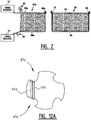
- the knot 68a is in existence, and the bale is approaching that length where the needle 42 is ready to swing into operation and present the strands 64a and 66a to the knotter 40 to start an operation cycle in which two consecutive knots are being formed.
- the loop 62 is made from two strands of binding material, i.e., one strand 64 along the top side of the bale and a second strand 66 along the bottom side of the bale and its two opposite, vertical ends.
- the strands 64 and 66 together form the continuous loop 62. Together, they fully circumscribe the bale.
- the knot 68 of a bale is typically a so called loop-knot. This means that the ends of the strands 64 and 66 of the knot 68 are released from a retained position so they can be pulled back instead of being cut by a moving knife arm 88 as will be described further to form a small loop on top of the knot.
- the knot 68 itself, thus holds the ends of the strands 64 and 66, united with the knot 68.
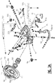
- FIGS. 3A , 3B , 3C, and 3D illustrate a first embodiment according to the invention
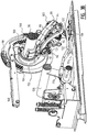
- FIGS. 4, 5, 6 and 7 illustrate a second embodiment.
- the knotter 40 is similar in many respects to the knotter disclosed in EP 1.584.227 in the name of the Applicant.
- the knotter 40 of FIGS. 3A , 3B and 4 comprises a generally circular element, also called knotter disc 76 that is secured to a drive shaft 78 for rotation with the latter through one full revolution when the clutch 38 is engaged.
- the shaft 78 is supported by a forwardly inclined frame 80 attached to the top of the bale case 22, and the frame 80 also supports the knotter components for forming the knots in response to rotation of the knotter disc 76.
- such components include a rotary bill hook member 82, supported by the frame 80 for rotation about an inclined axis 84; a twine disc 86 rearwardly of and adjacent to the bill hook 82 for holding strands 64a and 66a in position for engagement by the bill hook 82 during rotation of the latter; and removal means 92 for sweeping the connected strands from the bill hook 82 connected to an arm 88 pivotally attached to the frame 80 by a bolt 90.
- the strands 64a and 66a are held in notches 87a, 87b in the rotating twine disc 86 by a retainer or twine holder 220.
- the tensioning force of this retainer 220 to the twine disc 86 can be adjusted manually by changing the tension of a leaf-spring 200 when a bolt 210 is loosened or tightened.
- the lower end of the arm 88 is shaped in such a way that it opens away from the twine disc 86 beneath the bill hook 82.
- the arm 88 further carries a knife 94 between the bill hook 82 and the twine disc 86 for severing the strands 64a and 66a in response to a swinging movement of the arm 88 in the proper direction.
- Such movement of the arm 88 to operate the knife 94 also serves to bring the removal means 92 in engagement with a knot formed on the bill hook 82 for stripping such knot off of the bill hook 82.
- the removal means 92 preferably have a shape which is substantially complementary to the shape of the bill hook 82 to improve this sweeping of the bill hook.
- the knotter disc 76 is provided with a pinion 96 which is disposed for meshing engagement with a pair of circumferentially spaced gear stretches 98, 100 and 101 on the knotter disc 76.
- driving power is transmitted to the discs of the twine disc 86 through, a twine disc pinion 103, a worm gear drive 102 and a bevel gear 104 in position for sequential meshing engagement with a pair of circumferentially spaced gear sections 106, and 108 on the knotter disc 76.
- a finger 118 is located below the bill hook 82 and the arm 88 of the knotter 40 and is mounted on an upright pivot 120 for lateral swinging movement between a standby position illustrated in FIGS. 4 and 5 and a full-throw, laterally extended position somewhat beyond that illustrated in FIG. 6 .
- An operating link 122 attached at one end to the finger 118 and at the opposite end to a crank 124 serves to effect swinging of the finger 118.
- the crank 124 is in turn fixed to a transversely extending shaft 126 that extends to a point behind the knotter disc 76 where it may carry a second crank 128 as illustrated in FIG. 7 .
- the crank 128 is biased upwardly in a counter-clockwise direction by a coil spring 130 and carries a cam follower 132 at its outermost end.
- the follower 132 is in position for operating engagement with a double-lobed cam 134 fixed to the shaft 78 for rotation therewith, its lobes 136 and 138 being circumferentially spaced apart in accordance with the desired timed relationship between the finger 118 and the knot-forming components of the knotter 40.
- a second cam 140 having a peripheral land stretch 142 over approximately 180 degrees of its circumference and a peripheral valley stretch 144 over the remaining approximately 180 degrees of its circumference.
- Such stretches 142 and 144 are disposed for operating engagement with a cam roller 146 located at the outer end of a lever 148 that is fixed at its inner end to a transverse shaft 150.
- the lever 148, and hence the shaft 150 are biased in a counter-clockwise direction viewing FIG. 7 by a coil spring 152.
- the shaft 150 extends back out to the opposite side of the knotter disc 76 parallel with the shafts 78 and 126 to a point substantially in fore-and-aft alignment with the bill hook 82.
- the shaft 150 fixedly carries a rearwardly extending slack take-up device 154.
- the device 154 carries a pair of spaced rollers 156 and 158 at its rearmost end around which the strand 64a is entrained as illustrated in FIG. 4 .
- a length of the strand 64a is also looped upwardly around another roller 160 disposed above the device 154.
- the strand 64a may be clamped between a pair of opposed plates 162 and 164 ( FIG. 4 ) of a tensioning unit 166.
- the force with which the plates 162 and 164 clamp the strand 64a may be controlled by a wing nut 168 operating against a spring 170 that in turn presses against the movable plate 164.
- a tensioning unit similar to unit 166 may also be provided for the strand 66a, although such additional unit is not illustrated.
- the bale has reached its desired length and it is time to complete the loop around the bale and make the second knot in the loop.
- the strand 64a stretches along the top of the bale directly beneath the arm 88 but, at least for all effective purposes, is out of contact with the knotter 40. As illustrated in FIG.
- the finger 118 is actuated to swing inwardly and engage at least the strand 66a as illustrated in FIGS. 9 and 10 so as to assure that the strands 64a and 66a are both in proper position across the bill hook 82.
- the twine finger will hold the strands 64a, 66a on the bill hook 82 during the whole first knot process.
- the needle In presenting the strands 64a and 66a, the needle actually drapes the strands across the bill hook 82 and thence into awaiting notches of the twine disc 86, whereupon rotation of co-operating discs in the latter, in combination with a pressing twine holder 220, serve to firmly grip the strands and prevent their escape as the bill hook 82 begins its rotation as illustrated in FIG. 10 .
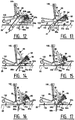
- the needle 42 reaches its highest position and starts to go down, see FIG. 11 .
- the twine disc 86 rotates a quarter of a turn and clamps the twines 64b and 66b firmly together.
- the two twines on the back of the needles are placed in the next notch of the twine disc for the second knot ( FIG. 12 ). While the needle goes down, the bill hook rotates to form the first knot. The knife arm swings out to cut the twines under the twine disc and sweeps the knot from the bill hook.
- a cam follower 85 which is connected to the upper lip 83a, engages an element having a cam shoulder (not shown).
- the cam follower will push the upper lip 83a away from the lower lip 83b, thus enabling the strands 64a and 66a to enter in between the two lips 83a and 83b while the bill hook is rotated.
- the twine disc 86 rotates in such a manner that the strands 64 and 66 are retained twice in different notches 87a, 87b in the twine disc 86, see FIG. 12 and the schematic top view of the twine disc 86 shown in FIG. 12A .
- two knots 70a and 68b can be formed during one knotting cycle as will be explained further, whereby the knife 94 severs the strands 64a and 66a from the strands 64b and 66b after the first knot 70 is formed and the removal part 92 removes the first knot from the bill hook 82, thus separating the two loops from each other.
- the adjustable leaf-spring 200 pushes against the twine holder 220, thus co-operating with the twine disc 86 to retain the strands.
- the cam shoulder 114 of the knotter disc 76 comes into engagement with the roller 110 of the arm 88 so as to swing the bottom of the latter, and hence the knife 94, across that portion of the strands between the bill hook 82 and the twine disc 86, thereby severing the same as illustrated in FIG. 12 and previously explained.
- the strands 64a and 66a extend from in between the lips 83a and 83b towards the twine disc 86.
- the knife 94 moves very closely alongside the bill hook 82, the free ends of the cut strands 64a and 66a extend only over a very short distance out of the lips 83a and 83b.
- the removal part 92 engages the strands 64a and 66a which are retained in a twisted manner around the bill hook 82. In so doing, the strand parts lying on top of the lip 83a are pulled over the strand parts laying in between the lips 83a and 83b, thereby forming the knot. As described above, since the free ends of the strands 64a and 66a are very short, they are pulled completely through the knot during its final formation, resulting in the so-called conventional knot 70a, as best seen in FIG. 13 . Besides completing the knot, further motion of the arm 88 also strips the finished knot 70a completely from the bill hook 82 and drops the completed loop on the bale as illustrated in FIG. 13 .
- the strands 64b and 66b are in position for initiating the second tying cycle which is started by the finger 118 swinging inwardly to engage the strands 64b and 66b and to assure that the strands 64b and 66b are properly positioned across and in engagement with the bill hook 82, see FIG. 15 , whereupon the latter and the twine disc 86 are operated by their second respective gear stretch 100 and gear section 108 on the knotter disc 76.
- the second knot 68b becomes formed as illustrated in FIG. 16 , whereupon the arm 88 is once again actuated, but this time by the second cam shoulder 116.
- the pressure of the twine holder 220 on the twine disc 86 and/or the shape of those elements should be such that a controlled slipping of the strands 64b and 66b is obtained during the formation of the second knot 68b. This may be reached by a suitable form of the twine disc 86, and in particular by a suitable shape of the recess in which the strands 64b and 66b are taken up.
- 3D illustrates an example of a possible twine disc having a first type of recess 87a in which the twines can be firmly clamped and a second type of recess 87b in which the twines are allowed to slip.
- the skilled person will understand that other shapes are possible and that it may be possible to provide more or less recesses in the twine disc.
- the twine disc could e.g. be provided with two notches spaced along the circumference at an angle which is larger than 90 degrees, in which case the rotation of the twine disc will have to be adapted accordingly.
- the pressure exerted by the leaf spring 200 could be regulated using a setting means 302 adapted to decrease this pressure when the gear 96 engages gear section 100.
- the twine holder 220 could be pushed away against the force of the leaf spring 200 during the formation of the second knot 68b.
- this regulating of the pressure/pushing away of the twine holder can be reached using any suitable mechanical or hydraulic transfer, e.g. by mechanically coupling the rotation of the knotter disc 76 and the setting means 302 for setting the pressure exerted on the twine holder 220.
- a different actuator 304 for biasing the twine holder 220 which actuator could be regulated e.g. by means of a control device for exerting a lower biasing during the second tying cycle.
- the operator would then be able to adjust the pressure exerted by the twine holder on the twine disk and the twines which are placed in the twine disk, such that the proper tension can be chosen, depending on e.g. the crops which is being baled, the speed of travel of the machine, the weather conditions, the quality of the twine, ...
- an adaption of shape of the recesses 87a, 87b and the use of a biasing means such as 302 or 304 may be combined.
- the cam shoulder 116 extends over a part of the circumference, see also reference numeral 117 so as to create a large shoulder which keeps the knife 94 in its furthest extended position after removal of the knot 68b of the bill hook 82.
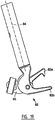
- This position of the cutter arm 88 is best illustrated in FIG. 3B .
- Pinion 96 will now engage gear stretch 101 and continue to rotate while the upper lip 83a opens a little.
- a supplementary gear section 109 providing a prolonged operation of the twine disc 86. In that way the strands 64b and 66b will no longer be retained between the twine disc 86 and the twine holder 220, causing a further slipping of the twines during the forming of the second knot.
- the knife 94 is very sharp, it will not be able to cut the strands because instead of holding the strands, the twine disc 86 is releasing them on account of the continued rotation of the twine disc 86 and the low pressure of the twine holder 220 on the twine disc 86, while the arm 88 continues moving and stripping of the almost completed knot from the bill hook 82, thus pulling the strands out of the twine disc 86.
- the supplementary gear section 109 is not necessary, and that substantially the same effect can be reached when the tensioning force of the leaf spring 200 to the twine holder 220 is sufficiently decreased.
- This knot 68b is the start of a new bight for the next bale.
- Such bight is in position to receive new material that is packed into the bale chamber 26 by the plunger 30, and the bight grows in length as additional lengths of the strands 64b and 66b are simultaneously pulled from their sources 72 and 74.
- the sequence returns to its starting point, whereupon the bight is closed by operation of the needle 42 to complete the loop around the bale and form the other knot.
Landscapes
- Life Sciences & Earth Sciences (AREA)
- Environmental Sciences (AREA)
- Basic Packing Technique (AREA)
- Preliminary Treatment Of Fibers (AREA)
- Braiding, Manufacturing Of Bobbin-Net Or Lace, And Manufacturing Of Nets By Knotting (AREA)
- Knitting Machines (AREA)
Claims (14)
- Knotersystem mit:einem Knoterhaken (82);einer Garnaufnahmeeinrichtung (220, 86, 200, 210, 302, 304) zum Halten von Garnen;einem Schneidarm (88), der zum Schneiden der Garne zwischen dem Knoterhaken (82) und der Garnaufnahmeeinrichtung (220, 86, 200, 210, 302, 304) und zum Abstreifen eines gebildeten Knotens (68a, 70) von dem Knoterhaken (82) eingerichtet ist, wobei er sich zwischen einer Ruheposition und einer ausgefahrenen Position bewegt;wobei ein erstes Antriebsmittel (76, 96, 98, 100, 101, 110, 112) dazu eingerichtet ist, dass der Knoterhaken (82) mindestens eine volle erste Drehung und eine zweite volle Drehung durchführt und dass der Schwenkarm (88) sich während eines vollen Betriebszyklus mindestens zwei Mal von der Ruheposition in die ausgefahrene Position und zurück bewegt, um einen ersten (70) beziehungsweise einen zweiten (68a), darauf folgenden Knoten zu bilden;wobei die Garnaufnahmeeinrichtung (220, 86, 200, 210, 302, 304) dazu eingerichtet ist, dass sie die Garne während der zweiten vollen Drehung des Knoterhakens (82) gleiten lässt, sodass ein Schneiden der Garne vermieden wird, wenn der zweite Knoten (68a) gebildet wird;wobei das erste Antriebsmittel (76, 96, 98, 100, 101, 110, 112) dazu eingerichtet ist, den Schneidarm (88) in der ausgefahrenen Position nach der zweiten Drehung des Knoterhakens (82) für eine vorbestimmte Zeitdauer zu halten, die ausreichend ist, um das Entfernen des zweiten Knotens (68a) von dem Knoterhaken (82) zu ermöglichen;dadurch gekennzeichnet, dass das erste Antriebsmittel (76, 101) dazu eingerichtet ist, dass der Knoterhaken (82) eine dritte volle Drehung während des Betriebszyklus durchführt und dass der Schneidarm (88) in der ausgefahrenen Position während mindestens eines ersten Teils der dritten Drehung gehalten wird.
- Knotersystem nach Anspruch 1, wobei der Knoterhaken (82) eine untere Lippe (83b), eine obere Lippe (83a) und eine Positionierungseinrichtung (85) zum Positionieren der oberen Lippe (83a) bezüglich der unteren Lippe (83b) aufweist; wobei die Positionierungseinrichtung (85) dazu eingerichtet ist, die obere Lippe (83a) von der unteren Lippe (83b) während mindestens eines ersten Teils der dritten Drehung weg zu bewegen.
- Knotersystem nach Anspruch 1 oder 2, wobei das erste Antriebsmittel (76, 101) ein Antriebsrad (96) und einen ersten, zweiten und dritten Gangabschnitt (98, 100, 101), die entlang des Umfangs einer Scheibe (76) vorgesehen sind, aufweist, wobei das Antriebsrad (96) dazu eingerichtet ist, mit den ersten, zweiten und dritten Gangabschnitten (98, 100, 101) zusammen zu wirken, sodass der Knoterhaken (82) die erste, zweite beziehungsweise dritte volle Drehung durchführt, wenn die Scheibe (76) gedreht wird.
- Knotersystem nach Anspruch 3, wobei das erste Antriebsmittel (76, 101) eine Nockenbahn (112) und einen Nockenmitnehmer (110) aufweist, wobei der Nockenmitnehmer (110) mit dem Schneidarm (88) verbunden ist, und wobei die Nockenbahn (112) in der Scheibe (76) oder in einem Element vorgesehen ist, das zur synchronen Drehung mit der Scheibe (76) angebracht wurde, und wobei das Antriebsmittel dazu eingerichtet ist, den Schneidarm (88) ein erstes Mal und ein zweites Mal von der Ruheposition in die ausgefahrene Position und zurück zu bewegen, wobei das zweite Mal die vorbestimmte Zeitdauer in der ausgefahrenen Position umfasst.
- Knotersystem nach einem der vorhergehenden Ansprüche, wobei die Garnaufnahmeeinrichtung eine Garnscheibe (86) und einen Garnhalter (220) aufweist, wobei der Garnhalter (220) dazu eingerichtet ist, Garne gegen die Garnscheibe (86) zu klemmen.
- Knotersystem nach Anspruch 5, das des Weiteren ein zweites Antriebsmittel (102, 103, 106, 108) aufweist, das zur Drehung der Garnscheibe (86) während einer ersten Drehung, wobei Garne zur Bildung des ersten Knotens (70) geklemmt werden, und zur Drehung der Garnscheibe (86) während einer zweiten Drehung eingerichtet ist, wobei die Garne während der Bildung des zweiten Knotens (68a) gleiten gelassen werden.
- Knotersystem nach Anspruch 5 oder 6, wobei die Garnscheibe (86) mit mindestens einer ersten und einer zweiten Einkerbung (87a, 87b) zur Aufnahme der Garne versehen sind.
- Knotersystem nach Anspruch 6 und 7, wobei die Garne sich in der ersten Einkerbung (87a) während der ersten Drehung und in der zweiten Einkerbung (87b) während der zweiten Drehung befinden, und wobei die zweite Einkerbung (87b) derart geformt ist, dass die Garne während des Bildens des zweiten Knotens (68a) aus der zweiten Einkerbung (87b) herausgleiten können.
- Knotersystem nach einem der Ansprüche 5 bis 8, wobei die Garnaufnahmeeinrichtung (220, 86, 200, 210, 302, 304) mit Vorspannungsmitteln (302, 200, 210; 304) zum Setzen einer Voreinstellung für die Klemmung durch den Garnhalter (220) versehen ist.
- Knotersystem nach Anspruch 9, wenn direkt oder indirekt abhängig von Anspruch 6, wobei die Vorspannungsmittel (302, 200, 210; 304) dazu eingerichtet sind, die erste, während der ersten Drehung verwendete Vorspannung auf eine zweite Vorspannung während der zweiten Drehung zu ändern, sodass während der ersten Vorspannung die Garne fest geklemmt sind, um die Garne zu schneiden, und während der zweiten Drehung die Garne gleiten können, um ein Schneiden der Garne zu verhindern.
- Knotersystem nach Anspruch 9 oder 10, wobei die Vorspannungsmittel (302, 200, 210; 304) eine Vorspannungsfeder (200), die dazu eingerichtet ist, den Garnhalter (220) gegen die Garnscheibe vorzuspannen, und Einstellmittel (302) zum automatischen Einstellen der Vorspannung aufweisen, die durch die Vorspannungsfeder (200) auf den Garnhalter (220) ausgeübt wird.
- Knotersystem nach Anspruch 9 oder 10, wobei die Vorspannungsmittel (302, 200, 210; 304) Betätigungsmittel (304) zum automatischen Einstellen der Vorspannung für das Klemmen durch den Garnhalter (220) aufweist.
- Knotersystem nach einem der vorhergehenden Ansprüche, wobei der Schneidarm (88) mit einer Schneideinrichtung (94) und einer Entfernungseinrichtung (92) zum Schneiden der Garne zwischen dem Knoterhaken (82) und der Garnaufnahmeeinrichtung (220, 86, 200, 210, 302, 304) und zum Abstreifen der Garne von dem Knoterhaken (82) versehen ist, während er sich von der Ruheposition in die ausgefahrene Position bewegt.
- Ballenpresse mit einer Mehrzahl von Knotersystemen nach einem der vorhergehenden Ansprüche.
Applications Claiming Priority (2)
| Application Number | Priority Date | Filing Date | Title |
|---|---|---|---|
| BE2012/0697A BE1021116B1 (nl) | 2012-10-16 | 2012-10-16 | Knopersysteem voor een balenpers |
| PCT/EP2013/070929 WO2014060245A1 (en) | 2012-10-16 | 2013-10-08 | Knotter system for a baler |
Publications (2)
| Publication Number | Publication Date |
|---|---|
| EP2908618A1 EP2908618A1 (de) | 2015-08-26 |
| EP2908618B1 true EP2908618B1 (de) | 2018-03-28 |
Family
ID=47435643
Family Applications (1)
| Application Number | Title | Priority Date | Filing Date |
|---|---|---|---|
| EP13774159.1A Active EP2908618B1 (de) | 2012-10-16 | 2013-10-08 | Knüpfmaschinensystem für eine ballenpresse |
Country Status (6)
| Country | Link |
|---|---|
| US (1) | US9883633B2 (de) |
| EP (1) | EP2908618B1 (de) |
| BE (1) | BE1021116B1 (de) |
| BR (1) | BR112015003224B1 (de) |
| RU (1) | RU2605332C2 (de) |
| WO (1) | WO2014060245A1 (de) |
Cited By (1)
| Publication number | Priority date | Publication date | Assignee | Title |
|---|---|---|---|---|
| EP4434323A1 (de) * | 2023-03-14 | 2024-09-25 | Kuhn-Geldrop B.V. | Ballenpresse und verfahren zum binden eines ballen |
Families Citing this family (14)
| Publication number | Priority date | Publication date | Assignee | Title |
|---|---|---|---|---|
| BE1021139B1 (nl) | 2013-04-02 | 2016-01-05 | Cnh Industrial Belgium Nv | Baalmeetsysteem en-werkwijze |
| PL3096600T3 (pl) * | 2014-01-22 | 2019-08-30 | Agco Corporation | Supłacz do prasy mający pojedynczą krzywkę, wykonujący podwójny węzeł na kokardkę |
| BE1023831B1 (nl) | 2016-09-22 | 2017-08-04 | Cnh Industrial Belgium Nv | Balenpers voor landbouwtoepassingen met verbeterd naaldkoppelingstoestel |
| BE1023832B1 (nl) | 2016-09-22 | 2017-08-04 | Cnh Industrial Belgium Nv | Verbeterd naaldkoppelingstoestel voor een balenpers voor landbouwtoepassingen |
| BE1023911B1 (nl) | 2016-11-10 | 2017-09-11 | Cnh Industrial Belgium Nv | Knopersysteem voor een balenpers |
| BE1024810B1 (nl) * | 2017-05-02 | 2018-07-03 | Cnh Industrial Belgium Nv | Verbeteringen in een knopersysteem voor een balenpers |
| BE1024808B1 (nl) * | 2017-05-02 | 2018-07-03 | Cnh Industrial Belgium Nv | Knopersysteem voor een balenpers |
| BE1024940B1 (nl) * | 2017-06-20 | 2018-08-21 | Cnh Industrial Belgium Nv | Balenpers met bescherming tegen overbelasting van de naalden |
| BE1026246B1 (nl) * | 2018-05-03 | 2019-12-02 | Cnh Ind Belgium Nv | Knopersysteem voor een balenpers |
| US11666003B2 (en) * | 2018-12-21 | 2023-06-06 | Agco Corporation | Quick-release lock for baler knotter head |
| EP3788865B1 (de) * | 2019-09-06 | 2021-11-03 | Rasspe Systemtechnik GmbH | Garnknoter |
| GB202011846D0 (en) * | 2020-07-30 | 2020-09-16 | Kuhn Geldrop Bv | Binding system and method |
| DE102020120445B4 (de) * | 2020-08-03 | 2025-03-20 | Maschinenfabrik Bernard Krone GmbH & Co. KG | Garnknoter und Ballenpresse mit einem Garnknoter |
| PL4039081T3 (pl) | 2021-02-04 | 2025-09-29 | Schumacher Bergische Werke Gmbh | Supłacz sznurka i sposób formowania dwóch węzłów na sznurku |
Family Cites Families (8)
| Publication number | Priority date | Publication date | Assignee | Title |
|---|---|---|---|---|
| DE3607694A1 (de) * | 1986-03-08 | 1987-09-10 | Rasspe Soehne P | Garnknuepfer nach dem system deering-hochdruck fuer ballenpressen und dergleichen |
| SU1521361A1 (ru) * | 1987-11-03 | 1989-11-15 | Всесоюзный Научно-Исследовательский Институт Льна | Устройство дл обв зки тюков стебельчатого материала |
| DE10206043A1 (de) * | 2002-02-14 | 2003-08-21 | Raussendorf Maschienen Und Ger | Knüpfereinrichtung für Großballenpressen |
| GB0407858D0 (en) * | 2004-04-07 | 2004-05-12 | Cnh Belgium Nv | Double knotting system for an agricultural baler |
| GB2418885A (en) * | 2004-10-06 | 2006-04-12 | Cnh Belgium Nv | Device for holding twines in a knotter |
| EP2198687B1 (de) * | 2008-12-17 | 2011-10-26 | Usines CLAAS France S.A.S. | Knotereinrichtung für eine landwirtschaftliche Großballenpresse |
| US8590945B2 (en) * | 2009-11-03 | 2013-11-26 | Rasspe Systemtechnik GMBH & Co., KG | Double-knot twine-knotter unit for large bale presses with a plurality of double-knot twine-knotters assembled on one knotter driveshaft |
| BE1021117B1 (nl) * | 2012-10-16 | 2015-11-16 | Cnh Industrial Belgium Nv | Verbeterd knopersysteem voor een balenpers |
-
2012
- 2012-10-16 BE BE2012/0697A patent/BE1021116B1/nl not_active IP Right Cessation
-
2013
- 2013-10-08 RU RU2015118330/13A patent/RU2605332C2/ru active
- 2013-10-08 EP EP13774159.1A patent/EP2908618B1/de active Active
- 2013-10-08 US US14/436,157 patent/US9883633B2/en active Active
- 2013-10-08 BR BR112015003224-9A patent/BR112015003224B1/pt not_active IP Right Cessation
- 2013-10-08 WO PCT/EP2013/070929 patent/WO2014060245A1/en not_active Ceased
Cited By (1)
| Publication number | Priority date | Publication date | Assignee | Title |
|---|---|---|---|---|
| EP4434323A1 (de) * | 2023-03-14 | 2024-09-25 | Kuhn-Geldrop B.V. | Ballenpresse und verfahren zum binden eines ballen |
Also Published As
| Publication number | Publication date |
|---|---|
| RU2015118330A (ru) | 2016-12-10 |
| US9883633B2 (en) | 2018-02-06 |
| BE1021116B1 (nl) | 2016-01-18 |
| BR112015003224B1 (pt) | 2019-10-29 |
| EP2908618A1 (de) | 2015-08-26 |
| WO2014060245A1 (en) | 2014-04-24 |
| RU2605332C2 (ru) | 2016-12-20 |
| BR112015003224A2 (pt) | 2017-08-08 |
| US20150272011A1 (en) | 2015-10-01 |
Similar Documents
| Publication | Publication Date | Title |
|---|---|---|
| US9883633B2 (en) | Knotter system for a baler | |
| EP3027005B1 (de) | Knotersystem mit verbessertem garnaufnehmer | |
| US7296828B2 (en) | Double knotting system for an agricultural baler | |
| EP3618606B1 (de) | Knotersystem für eine ballenpresse | |
| EP2108247B1 (de) | Knüpfmaschine für eine Ballenpresse | |
| US4142746A (en) | Strand tying mechanism | |
| EP3618605B1 (de) | Verbesserungen an einem knotersystem für eine ballenpresse | |
| EP2721920B1 (de) | Verbessertes Schleifenknüpfsystem für eine Ballenpresse | |
| EP3320770B1 (de) | Knüpfmaschinensystem für eine ballenpresse | |
| EP3563666B1 (de) | Knüpfmaschine für eine ballenpresse | |
| CA3175438A1 (en) | Tailless knotter for baler |
Legal Events
| Date | Code | Title | Description |
|---|---|---|---|
| PUAI | Public reference made under article 153(3) epc to a published international application that has entered the european phase |
Free format text: ORIGINAL CODE: 0009012 |
|
| 17P | Request for examination filed |
Effective date: 20150518 |
|
| AK | Designated contracting states |
Kind code of ref document: A1 Designated state(s): AL AT BE BG CH CY CZ DE DK EE ES FI FR GB GR HR HU IE IS IT LI LT LU LV MC MK MT NL NO PL PT RO RS SE SI SK SM TR |
|
| AX | Request for extension of the european patent |
Extension state: BA ME |
|
| DAX | Request for extension of the european patent (deleted) | ||
| GRAP | Despatch of communication of intention to grant a patent |
Free format text: ORIGINAL CODE: EPIDOSNIGR1 |
|
| STAA | Information on the status of an ep patent application or granted ep patent |
Free format text: STATUS: GRANT OF PATENT IS INTENDED |
|
| INTG | Intention to grant announced |
Effective date: 20171019 |
|
| RIN1 | Information on inventor provided before grant (corrected) |
Inventor name: DEMON, FREDERIK |
|
| GRAS | Grant fee paid |
Free format text: ORIGINAL CODE: EPIDOSNIGR3 |
|
| GRAA | (expected) grant |
Free format text: ORIGINAL CODE: 0009210 |
|
| STAA | Information on the status of an ep patent application or granted ep patent |
Free format text: STATUS: THE PATENT HAS BEEN GRANTED |
|
| AK | Designated contracting states |
Kind code of ref document: B1 Designated state(s): AL AT BE BG CH CY CZ DE DK EE ES FI FR GB GR HR HU IE IS IT LI LT LU LV MC MK MT NL NO PL PT RO RS SE SI SK SM TR |
|
| REG | Reference to a national code |
Ref country code: GB Ref legal event code: FG4D |
|
| REG | Reference to a national code |
Ref country code: CH Ref legal event code: EP |
|
| REG | Reference to a national code |
Ref country code: AT Ref legal event code: REF Ref document number: 982523 Country of ref document: AT Kind code of ref document: T Effective date: 20180415 |
|
| REG | Reference to a national code |
Ref country code: IE Ref legal event code: FG4D |
|
| REG | Reference to a national code |
Ref country code: DE Ref legal event code: R096 Ref document number: 602013035101 Country of ref document: DE |
|
| PG25 | Lapsed in a contracting state [announced via postgrant information from national office to epo] |
Ref country code: FI Free format text: LAPSE BECAUSE OF FAILURE TO SUBMIT A TRANSLATION OF THE DESCRIPTION OR TO PAY THE FEE WITHIN THE PRESCRIBED TIME-LIMIT Effective date: 20180328 Ref country code: LT Free format text: LAPSE BECAUSE OF FAILURE TO SUBMIT A TRANSLATION OF THE DESCRIPTION OR TO PAY THE FEE WITHIN THE PRESCRIBED TIME-LIMIT Effective date: 20180328 Ref country code: HR Free format text: LAPSE BECAUSE OF FAILURE TO SUBMIT A TRANSLATION OF THE DESCRIPTION OR TO PAY THE FEE WITHIN THE PRESCRIBED TIME-LIMIT Effective date: 20180328 Ref country code: NO Free format text: LAPSE BECAUSE OF FAILURE TO SUBMIT A TRANSLATION OF THE DESCRIPTION OR TO PAY THE FEE WITHIN THE PRESCRIBED TIME-LIMIT Effective date: 20180628 |
|
| REG | Reference to a national code |
Ref country code: NL Ref legal event code: MP Effective date: 20180328 |
|
| REG | Reference to a national code |
Ref country code: LT Ref legal event code: MG4D |
|
| PG25 | Lapsed in a contracting state [announced via postgrant information from national office to epo] |
Ref country code: BG Free format text: LAPSE BECAUSE OF FAILURE TO SUBMIT A TRANSLATION OF THE DESCRIPTION OR TO PAY THE FEE WITHIN THE PRESCRIBED TIME-LIMIT Effective date: 20180628 Ref country code: RS Free format text: LAPSE BECAUSE OF FAILURE TO SUBMIT A TRANSLATION OF THE DESCRIPTION OR TO PAY THE FEE WITHIN THE PRESCRIBED TIME-LIMIT Effective date: 20180328 Ref country code: SE Free format text: LAPSE BECAUSE OF FAILURE TO SUBMIT A TRANSLATION OF THE DESCRIPTION OR TO PAY THE FEE WITHIN THE PRESCRIBED TIME-LIMIT Effective date: 20180328 Ref country code: GR Free format text: LAPSE BECAUSE OF FAILURE TO SUBMIT A TRANSLATION OF THE DESCRIPTION OR TO PAY THE FEE WITHIN THE PRESCRIBED TIME-LIMIT Effective date: 20180629 Ref country code: LV Free format text: LAPSE BECAUSE OF FAILURE TO SUBMIT A TRANSLATION OF THE DESCRIPTION OR TO PAY THE FEE WITHIN THE PRESCRIBED TIME-LIMIT Effective date: 20180328 |
|
| REG | Reference to a national code |
Ref country code: FR Ref legal event code: PLFP Year of fee payment: 6 |
|
| PG25 | Lapsed in a contracting state [announced via postgrant information from national office to epo] |
Ref country code: EE Free format text: LAPSE BECAUSE OF FAILURE TO SUBMIT A TRANSLATION OF THE DESCRIPTION OR TO PAY THE FEE WITHIN THE PRESCRIBED TIME-LIMIT Effective date: 20180328 Ref country code: PL Free format text: LAPSE BECAUSE OF FAILURE TO SUBMIT A TRANSLATION OF THE DESCRIPTION OR TO PAY THE FEE WITHIN THE PRESCRIBED TIME-LIMIT Effective date: 20180328 Ref country code: NL Free format text: LAPSE BECAUSE OF FAILURE TO SUBMIT A TRANSLATION OF THE DESCRIPTION OR TO PAY THE FEE WITHIN THE PRESCRIBED TIME-LIMIT Effective date: 20180328 Ref country code: RO Free format text: LAPSE BECAUSE OF FAILURE TO SUBMIT A TRANSLATION OF THE DESCRIPTION OR TO PAY THE FEE WITHIN THE PRESCRIBED TIME-LIMIT Effective date: 20180328 Ref country code: ES Free format text: LAPSE BECAUSE OF FAILURE TO SUBMIT A TRANSLATION OF THE DESCRIPTION OR TO PAY THE FEE WITHIN THE PRESCRIBED TIME-LIMIT Effective date: 20180328 Ref country code: AL Free format text: LAPSE BECAUSE OF FAILURE TO SUBMIT A TRANSLATION OF THE DESCRIPTION OR TO PAY THE FEE WITHIN THE PRESCRIBED TIME-LIMIT Effective date: 20180328 |
|
| PG25 | Lapsed in a contracting state [announced via postgrant information from national office to epo] |
Ref country code: SM Free format text: LAPSE BECAUSE OF FAILURE TO SUBMIT A TRANSLATION OF THE DESCRIPTION OR TO PAY THE FEE WITHIN THE PRESCRIBED TIME-LIMIT Effective date: 20180328 Ref country code: SK Free format text: LAPSE BECAUSE OF FAILURE TO SUBMIT A TRANSLATION OF THE DESCRIPTION OR TO PAY THE FEE WITHIN THE PRESCRIBED TIME-LIMIT Effective date: 20180328 Ref country code: CZ Free format text: LAPSE BECAUSE OF FAILURE TO SUBMIT A TRANSLATION OF THE DESCRIPTION OR TO PAY THE FEE WITHIN THE PRESCRIBED TIME-LIMIT Effective date: 20180328 |
|
| REG | Reference to a national code |
Ref country code: AT Ref legal event code: MK05 Ref document number: 982523 Country of ref document: AT Kind code of ref document: T Effective date: 20180328 |
|
| PG25 | Lapsed in a contracting state [announced via postgrant information from national office to epo] |
Ref country code: PT Free format text: LAPSE BECAUSE OF FAILURE TO SUBMIT A TRANSLATION OF THE DESCRIPTION OR TO PAY THE FEE WITHIN THE PRESCRIBED TIME-LIMIT Effective date: 20180730 |
|
| REG | Reference to a national code |
Ref country code: DE Ref legal event code: R097 Ref document number: 602013035101 Country of ref document: DE |
|
| PG25 | Lapsed in a contracting state [announced via postgrant information from national office to epo] |
Ref country code: AT Free format text: LAPSE BECAUSE OF FAILURE TO SUBMIT A TRANSLATION OF THE DESCRIPTION OR TO PAY THE FEE WITHIN THE PRESCRIBED TIME-LIMIT Effective date: 20180328 Ref country code: DK Free format text: LAPSE BECAUSE OF FAILURE TO SUBMIT A TRANSLATION OF THE DESCRIPTION OR TO PAY THE FEE WITHIN THE PRESCRIBED TIME-LIMIT Effective date: 20180328 |
|
| PLBE | No opposition filed within time limit |
Free format text: ORIGINAL CODE: 0009261 |
|
| STAA | Information on the status of an ep patent application or granted ep patent |
Free format text: STATUS: NO OPPOSITION FILED WITHIN TIME LIMIT |
|
| 26N | No opposition filed |
Effective date: 20190103 |
|
| PG25 | Lapsed in a contracting state [announced via postgrant information from national office to epo] |
Ref country code: SI Free format text: LAPSE BECAUSE OF FAILURE TO SUBMIT A TRANSLATION OF THE DESCRIPTION OR TO PAY THE FEE WITHIN THE PRESCRIBED TIME-LIMIT Effective date: 20180328 |
|
| REG | Reference to a national code |
Ref country code: CH Ref legal event code: PL |
|
| PG25 | Lapsed in a contracting state [announced via postgrant information from national office to epo] |
Ref country code: MC Free format text: LAPSE BECAUSE OF FAILURE TO SUBMIT A TRANSLATION OF THE DESCRIPTION OR TO PAY THE FEE WITHIN THE PRESCRIBED TIME-LIMIT Effective date: 20180328 Ref country code: LU Free format text: LAPSE BECAUSE OF NON-PAYMENT OF DUE FEES Effective date: 20181008 |
|
| REG | Reference to a national code |
Ref country code: IE Ref legal event code: MM4A |
|
| PG25 | Lapsed in a contracting state [announced via postgrant information from national office to epo] |
Ref country code: CH Free format text: LAPSE BECAUSE OF NON-PAYMENT OF DUE FEES Effective date: 20181031 Ref country code: LI Free format text: LAPSE BECAUSE OF NON-PAYMENT OF DUE FEES Effective date: 20181031 |
|
| PG25 | Lapsed in a contracting state [announced via postgrant information from national office to epo] |
Ref country code: IE Free format text: LAPSE BECAUSE OF NON-PAYMENT OF DUE FEES Effective date: 20181008 |
|
| PG25 | Lapsed in a contracting state [announced via postgrant information from national office to epo] |
Ref country code: MT Free format text: LAPSE BECAUSE OF NON-PAYMENT OF DUE FEES Effective date: 20181008 |
|
| PG25 | Lapsed in a contracting state [announced via postgrant information from national office to epo] |
Ref country code: TR Free format text: LAPSE BECAUSE OF FAILURE TO SUBMIT A TRANSLATION OF THE DESCRIPTION OR TO PAY THE FEE WITHIN THE PRESCRIBED TIME-LIMIT Effective date: 20180328 |
|
| PG25 | Lapsed in a contracting state [announced via postgrant information from national office to epo] |
Ref country code: HU Free format text: LAPSE BECAUSE OF FAILURE TO SUBMIT A TRANSLATION OF THE DESCRIPTION OR TO PAY THE FEE WITHIN THE PRESCRIBED TIME-LIMIT; INVALID AB INITIO Effective date: 20131008 Ref country code: CY Free format text: LAPSE BECAUSE OF FAILURE TO SUBMIT A TRANSLATION OF THE DESCRIPTION OR TO PAY THE FEE WITHIN THE PRESCRIBED TIME-LIMIT Effective date: 20180328 Ref country code: MK Free format text: LAPSE BECAUSE OF NON-PAYMENT OF DUE FEES Effective date: 20180328 |
|
| PG25 | Lapsed in a contracting state [announced via postgrant information from national office to epo] |
Ref country code: IS Free format text: LAPSE BECAUSE OF FAILURE TO SUBMIT A TRANSLATION OF THE DESCRIPTION OR TO PAY THE FEE WITHIN THE PRESCRIBED TIME-LIMIT Effective date: 20180728 |
|
| PGFP | Annual fee paid to national office [announced via postgrant information from national office to epo] |
Ref country code: BE Payment date: 20241023 Year of fee payment: 12 |
|
| PGFP | Annual fee paid to national office [announced via postgrant information from national office to epo] |
Ref country code: DE Payment date: 20251028 Year of fee payment: 13 |
|
| PGFP | Annual fee paid to national office [announced via postgrant information from national office to epo] |
Ref country code: GB Payment date: 20251021 Year of fee payment: 13 |
|
| PGFP | Annual fee paid to national office [announced via postgrant information from national office to epo] |
Ref country code: IT Payment date: 20251024 Year of fee payment: 13 |
|
| PGFP | Annual fee paid to national office [announced via postgrant information from national office to epo] |
Ref country code: FR Payment date: 20251027 Year of fee payment: 13 |