EP2907585B1 - Procédé et dispositif d'application d'un fluide à la surface d'un composant - Google Patents
Procédé et dispositif d'application d'un fluide à la surface d'un composant Download PDFInfo
- Publication number
- EP2907585B1 EP2907585B1 EP15154481.4A EP15154481A EP2907585B1 EP 2907585 B1 EP2907585 B1 EP 2907585B1 EP 15154481 A EP15154481 A EP 15154481A EP 2907585 B1 EP2907585 B1 EP 2907585B1
- Authority
- EP
- European Patent Office
- Prior art keywords
- component
- coating system
- mounts
- base plate
- component mounts
- Prior art date
- Legal status (The legal status is an assumption and is not a legal conclusion. Google has not performed a legal analysis and makes no representation as to the accuracy of the status listed.)
- Active
Links
- 238000000034 method Methods 0.000 title claims description 22
- 239000012530 fluid Substances 0.000 title claims description 17
- 238000000576 coating method Methods 0.000 claims description 40
- 239000011248 coating agent Substances 0.000 claims description 39
- 238000001514 detection method Methods 0.000 claims description 25
- 230000005291 magnetic effect Effects 0.000 claims description 18
- 239000000853 adhesive Substances 0.000 description 5
- 230000001070 adhesive effect Effects 0.000 description 5
- 230000005294 ferromagnetic effect Effects 0.000 description 4
- 238000005304 joining Methods 0.000 description 4
- 238000004519 manufacturing process Methods 0.000 description 4
- 230000003287 optical effect Effects 0.000 description 4
- 238000007789 sealing Methods 0.000 description 4
- 230000006870 function Effects 0.000 description 3
- 238000009434 installation Methods 0.000 description 3
- 239000000565 sealant Substances 0.000 description 3
- 239000011324 bead Substances 0.000 description 2
- 239000000463 material Substances 0.000 description 2
- 238000012360 testing method Methods 0.000 description 2
- TVEXGJYMHHTVKP-UHFFFAOYSA-N 6-oxabicyclo[3.2.1]oct-3-en-7-one Chemical compound C1C2C(=O)OC1C=CC2 TVEXGJYMHHTVKP-UHFFFAOYSA-N 0.000 description 1
- 241001136792 Alle Species 0.000 description 1
- 230000006978 adaptation Effects 0.000 description 1
- 238000004026 adhesive bonding Methods 0.000 description 1
- 230000005540 biological transmission Effects 0.000 description 1
- 238000012937 correction Methods 0.000 description 1
- 230000007423 decrease Effects 0.000 description 1
- 230000001419 dependent effect Effects 0.000 description 1
- 238000011161 development Methods 0.000 description 1
- 230000018109 developmental process Effects 0.000 description 1
- 239000003822 epoxy resin Substances 0.000 description 1
- 238000011156 evaluation Methods 0.000 description 1
- 239000003302 ferromagnetic material Substances 0.000 description 1
- 239000003292 glue Substances 0.000 description 1
- 239000012943 hotmelt Substances 0.000 description 1
- 238000003780 insertion Methods 0.000 description 1
- 230000037431 insertion Effects 0.000 description 1
- 239000007788 liquid Substances 0.000 description 1
- 235000011837 pasties Nutrition 0.000 description 1
- 229920000647 polyepoxide Polymers 0.000 description 1
- 229920001296 polysiloxane Polymers 0.000 description 1
- 239000004814 polyurethane Substances 0.000 description 1
- 229920002635 polyurethane Polymers 0.000 description 1
- 238000002360 preparation method Methods 0.000 description 1
- 238000003860 storage Methods 0.000 description 1
- 230000003936 working memory Effects 0.000 description 1
Images

Classifications
-
- B—PERFORMING OPERATIONS; TRANSPORTING
- B05—SPRAYING OR ATOMISING IN GENERAL; APPLYING FLUENT MATERIALS TO SURFACES, IN GENERAL
- B05C—APPARATUS FOR APPLYING FLUENT MATERIALS TO SURFACES, IN GENERAL
- B05C13/00—Means for manipulating or holding work, e.g. for separate articles
- B05C13/02—Means for manipulating or holding work, e.g. for separate articles for particular articles
-
- B—PERFORMING OPERATIONS; TRANSPORTING
- B05—SPRAYING OR ATOMISING IN GENERAL; APPLYING FLUENT MATERIALS TO SURFACES, IN GENERAL
- B05B—SPRAYING APPARATUS; ATOMISING APPARATUS; NOZZLES
- B05B12/00—Arrangements for controlling delivery; Arrangements for controlling the spray area
- B05B12/08—Arrangements for controlling delivery; Arrangements for controlling the spray area responsive to condition of liquid or other fluent material to be discharged, of ambient medium or of target ; responsive to condition of spray devices or of supply means, e.g. pipes, pumps or their drive means
- B05B12/12—Arrangements for controlling delivery; Arrangements for controlling the spray area responsive to condition of liquid or other fluent material to be discharged, of ambient medium or of target ; responsive to condition of spray devices or of supply means, e.g. pipes, pumps or their drive means responsive to conditions of ambient medium or target, e.g. humidity, temperature position or movement of the target relative to the spray apparatus
- B05B12/122—Arrangements for controlling delivery; Arrangements for controlling the spray area responsive to condition of liquid or other fluent material to be discharged, of ambient medium or of target ; responsive to condition of spray devices or of supply means, e.g. pipes, pumps or their drive means responsive to conditions of ambient medium or target, e.g. humidity, temperature position or movement of the target relative to the spray apparatus responsive to presence or shape of target
-
- B—PERFORMING OPERATIONS; TRANSPORTING
- B05—SPRAYING OR ATOMISING IN GENERAL; APPLYING FLUENT MATERIALS TO SURFACES, IN GENERAL
- B05B—SPRAYING APPARATUS; ATOMISING APPARATUS; NOZZLES
- B05B13/00—Machines or plants for applying liquids or other fluent materials to surfaces of objects or other work by spraying, not covered by groups B05B1/00 - B05B11/00
- B05B13/02—Means for supporting work; Arrangement or mounting of spray heads; Adaptation or arrangement of means for feeding work
- B05B13/0285—Stands for supporting individual articles to be sprayed, e.g. doors, vehicle body parts
-
- B—PERFORMING OPERATIONS; TRANSPORTING
- B05—SPRAYING OR ATOMISING IN GENERAL; APPLYING FLUENT MATERIALS TO SURFACES, IN GENERAL
- B05B—SPRAYING APPARATUS; ATOMISING APPARATUS; NOZZLES
- B05B13/00—Machines or plants for applying liquids or other fluent materials to surfaces of objects or other work by spraying, not covered by groups B05B1/00 - B05B11/00
- B05B13/02—Means for supporting work; Arrangement or mounting of spray heads; Adaptation or arrangement of means for feeding work
- B05B13/04—Means for supporting work; Arrangement or mounting of spray heads; Adaptation or arrangement of means for feeding work the spray heads being moved during spraying operation
- B05B13/0431—Means for supporting work; Arrangement or mounting of spray heads; Adaptation or arrangement of means for feeding work the spray heads being moved during spraying operation with spray heads moved by robots or articulated arms, e.g. for applying liquid or other fluent material to 3D-surfaces
-
- B—PERFORMING OPERATIONS; TRANSPORTING
- B05—SPRAYING OR ATOMISING IN GENERAL; APPLYING FLUENT MATERIALS TO SURFACES, IN GENERAL
- B05C—APPARATUS FOR APPLYING FLUENT MATERIALS TO SURFACES, IN GENERAL
- B05C5/00—Apparatus in which liquid or other fluent material is projected, poured or allowed to flow on to the surface of the work
- B05C5/02—Apparatus in which liquid or other fluent material is projected, poured or allowed to flow on to the surface of the work the liquid or other fluent material being discharged through an outlet orifice by pressure, e.g. from an outlet device in contact or almost in contact, with the work
- B05C5/0208—Apparatus in which liquid or other fluent material is projected, poured or allowed to flow on to the surface of the work the liquid or other fluent material being discharged through an outlet orifice by pressure, e.g. from an outlet device in contact or almost in contact, with the work for applying liquid or other fluent material to separate articles
- B05C5/0212—Apparatus in which liquid or other fluent material is projected, poured or allowed to flow on to the surface of the work the liquid or other fluent material being discharged through an outlet orifice by pressure, e.g. from an outlet device in contact or almost in contact, with the work for applying liquid or other fluent material to separate articles only at particular parts of the articles
- B05C5/0216—Apparatus in which liquid or other fluent material is projected, poured or allowed to flow on to the surface of the work the liquid or other fluent material being discharged through an outlet orifice by pressure, e.g. from an outlet device in contact or almost in contact, with the work for applying liquid or other fluent material to separate articles only at particular parts of the articles by relative movement of article and outlet according to a predetermined path
-
- B—PERFORMING OPERATIONS; TRANSPORTING
- B05—SPRAYING OR ATOMISING IN GENERAL; APPLYING FLUENT MATERIALS TO SURFACES, IN GENERAL
- B05B—SPRAYING APPARATUS; ATOMISING APPARATUS; NOZZLES
- B05B12/00—Arrangements for controlling delivery; Arrangements for controlling the spray area
-
- B—PERFORMING OPERATIONS; TRANSPORTING
- B05—SPRAYING OR ATOMISING IN GENERAL; APPLYING FLUENT MATERIALS TO SURFACES, IN GENERAL
- B05D—PROCESSES FOR APPLYING FLUENT MATERIALS TO SURFACES, IN GENERAL
- B05D1/00—Processes for applying liquids or other fluent materials
- B05D1/26—Processes for applying liquids or other fluent materials performed by applying the liquid or other fluent material from an outlet device in contact with, or almost in contact with, the surface
-
- B—PERFORMING OPERATIONS; TRANSPORTING
- B23—MACHINE TOOLS; METAL-WORKING NOT OTHERWISE PROVIDED FOR
- B23Q—DETAILS, COMPONENTS, OR ACCESSORIES FOR MACHINE TOOLS, e.g. ARRANGEMENTS FOR COPYING OR CONTROLLING; MACHINE TOOLS IN GENERAL CHARACTERISED BY THE CONSTRUCTION OF PARTICULAR DETAILS OR COMPONENTS; COMBINATIONS OR ASSOCIATIONS OF METAL-WORKING MACHINES, NOT DIRECTED TO A PARTICULAR RESULT
- B23Q17/00—Arrangements for observing, indicating or measuring on machine tools
- B23Q17/002—Arrangements for observing, indicating or measuring on machine tools for indicating or measuring the holding action of work or tool holders
- B23Q17/003—Arrangements for observing, indicating or measuring on machine tools for indicating or measuring the holding action of work or tool holders by measuring a position
-
- B—PERFORMING OPERATIONS; TRANSPORTING
- B23—MACHINE TOOLS; METAL-WORKING NOT OTHERWISE PROVIDED FOR
- B23Q—DETAILS, COMPONENTS, OR ACCESSORIES FOR MACHINE TOOLS, e.g. ARRANGEMENTS FOR COPYING OR CONTROLLING; MACHINE TOOLS IN GENERAL CHARACTERISED BY THE CONSTRUCTION OF PARTICULAR DETAILS OR COMPONENTS; COMBINATIONS OR ASSOCIATIONS OF METAL-WORKING MACHINES, NOT DIRECTED TO A PARTICULAR RESULT
- B23Q3/00—Devices holding, supporting, or positioning work or tools, of a kind normally removable from the machine
- B23Q3/02—Devices holding, supporting, or positioning work or tools, of a kind normally removable from the machine for mounting on a work-table, tool-slide, or analogous part
- B23Q3/06—Work-clamping means
- B23Q3/062—Work-clamping means adapted for holding workpieces having a special form or being made from a special material
Definitions
- the present invention relates to a method for applying a fluid to a surface of a component, wherein the component is arranged on a plurality of component holders in a computer-controlled coating system, detects the position of the component and applies the fluid to the surface of the component according to a preprogrammed coating profile.
- a computer-controlled coating plant of this kind is in WO2013 / 175392 A1 disclosed.
- the computer-controlled coating systems are usually CNC systems in which complex sealing courses along the contour of the joining surfaces are applied to the component with high precision by means of three-dimensionally controllable metering systems can.
- CNC systems in which complex sealing courses along the contour of the joining surfaces are applied to the component with high precision by means of three-dimensionally controllable metering systems can.
- automated application of the fluid precise positioning of the component in the coating system is essential.
- interchangeable base plates are usually produced for each component on which pin-like component holders are firmly mounted, in which the component to be coated are used.
- Each baseplate usually has a specific plug or socket so that the baseplate can be connected to the CNC controller via an electrical plug connection.
- the coating system thus recognizes which specific base plate is currently installed. By detecting the base plate, the controller also detects the position of the component to be coated. Accordingly, the respective coating program can be selected and the component can be exactly approached with the dosing head in order to apply a bead of the fluid to the surface in accordance with the desired course of the seal.
- the present invention is therefore based on the technical problem of providing a method for applying a fluid to a surface of a component, which is cheaper and therefore particularly suitable for small and pre-series production.
- the invention thus relates to a method for applying a fluid to a surface of a component, wherein the component is arranged on a plurality of component receptacles in a computer-controlled coating system, the position of the component detects and applies the fluid according to a preprogrammed coating profile on the surface of the component.
- the inventive method is characterized in that at least one of the component receptacles is mounted freely positionable on a base plate.
- component holders are sufficient for a stable arrangement of the component in the coating system.
- component receptacles may be provided, for example, four or five component holders.
- a component receptacle is firmly connected to the base plate, while the remaining component receptacles can be mounted freely positionable.
- the position of the permanently mounted component receptacle can identify, for example, different base plates, so that the coating system can also recognize without electrical plug connection, which base plate is currently mounted.
- the component is particularly preferably arranged by means of three to five freely positionable component holders, in particular by means of three or four freely positionable component holders, in the coating system.
- At least one component receptacle is height-adjustable.
- all component receptacles are height adjustable. Due to the height adjustability of the component holders, a specific position of the surface to be coated can be defined in space. Often it is necessary, for example, that the surface to be coated is aligned as exactly as possible horizontally. To determine the altitude of the surface to be coated of the component can height-adjustable gauges are used, which ensure the flatness and the constant component height.
- the component receptacles are freely positionable on the base plate, on the other hand, after setting a specific position, later slippage of the component receptacles must be precluded.
- the component holders are therefore also arrested or fixable on the base plate.
- a particularly simple locking / fixing of the component receptacles is ensured for example by the fact that the base plate consists of a ferromagnetic material and the component receptacles are each provided with magnetic feet.
- the magnetic feet may, for example, comprise a mechanical switch which switches a rotatable permanent magnet arranged in the magnetic base so that the magnetic feet can either adhere to the base plate or be detached therefrom. The operator can therefore very quickly and reliably switch between loosening and fixing the component.
- each component holder can be provided, for example, with an indexing pin, which engages in a predetermined opening or depression in the component, so that the component is precisely fixed at this point.
- Another head part may be formed as a support pin on which the component rests on a locally not exactly defined position.
- At least two of the component holders used should be equipped with an index pin so that the exact position of the component is set parallel to the plane of the base plate.
- the component receptacle can also be designed such that the component receptacle acts as a support element without an index pin.
- a detection pin can be provided, with the aid of which the exact position of the component holder can be detected or set up.
- the arrangement and position detection of the component takes place in the coating system in that arranging the component receptacles at predetermined locations on the base plate.
- the component can be certain coordinates stored for the nominal positions of the component receptacles in the computer-controlled coating system.
- This target position of the component receptacles on the base plate can then be displayed, for example, by an optical positioning device, so that the operating personnel can position the component receptacle accordingly.
- the exact position of the respective component holder is detected and / or displayed by means of a laser beam.
- the coating installation has a laser positioning device which emits a laser beam perpendicularly in the direction of the base plate and detects the reflected light by means of a detector.
- the component holder is provided for accurate positioning with a detection pin whose top is formed by a plate-like disc, in the center of a recess with a diameter in the desired positioning accuracy is recessed.
- the detector in the laser positioning device detects a reflection of the laser beam when it hits the disc of the detection pin outside the depression. As soon as the component holder is exactly positioned by the operator, the laser beam disappears into the recess in the center of the disk.
- the detector detects this by drastically reducing the intensity of the reflected light or, if the bottom of the well is mirrored, by drastically increasing the intensity of the reflected light.
- the system then signals the correct positioning to the operating personnel so that the operating personnel can fix the component holder in this position on the base plate. This positioning is carried out successively for all freely positionable component holders. After exact positioning of the component receptacles, the head part is in each case according to the requirements of the respective component against an index pin or a support pin or serves after removal of the detection pin itself as a component support.
- the exact position of the respective component holder is detected and / or displayed by means of a mechanical position sensor.
- the nominal positions of the component receptacles can be determined on the basis of digitized models of the respective components to be coated, taking into account, if appropriate, the desired coating course, calculated and displayed.
- the setpoint positions of the component receptacles for a new component to be coated can also be detected by means of the optical positioning device, the laser positioning device.
- the operator first arranges the new component to be coated on three to five component receptacles in the desired orientation and height on the base plate. Subsequently, the component is removed and the index pins and / or support pins of the component holders are replaced by detection pins.
- the operator positions the laser on the individual component receptacles so that the laser beam strikes in each case in the recess of the detection pin. As soon as the system signals the correct positioning of the laser, this position is saved as the target position of the respective component holder.
- the invention also provides a computer-controlled coating system for applying a fluid to a surface of a component having at least one base plate on which a plurality of component receptacles are freely positionable, at least one movable dosing head for applying the fluid to the surface of the component and at least one device for detecting the Target positions of the component holders and / or for displaying the desired positions of the component holders.
- FIG. 1 shows a schematic representation of the essential components of a coating system 10 according to the invention, with which a fluid from a (not shown) reservoir can be applied by means of a movable dosing tip 11 on the surface 12 of a component 13.
- the metering tip 11 is movable in the example shown by means of a first drive 14 in the x and z directions, while a second drive 15 ensures movement of the mounted on a ferromagnetic base plate 16 component 13 in the y direction.
- the metering tip 11 can apply an arbitrarily complex fluid course to the surface 12 of the component 13.
- a sealant can be applied along the contour of a housing half, for example a motor housing.
- the component 13 is mounted on four component receptacles 17, 18, 19, 20.
- Each component receptacle has magnetic feet 17a, 18a, 19a, 20a, so that the component receptacles on the one hand on the ferromagnetic base plates 16 are freely movable, on the other hand, however, if necessary, also on the base plate 16 can be fixed.
- FIG. 2 is the base plate 16 with the component holders 17, 18, 19, 20 without the in FIG. 1 shown component 13 shown in more detail.
- the dosing tip 11 is arranged in an application head 23 connected to the drive 4, which also comprises an optical positioning device.
- the optical positioning device emits a laser beam 24 in the direction of the base plate, the reflections of which are detected by a detector (not shown) arranged on the underside of the application head 23.
- the laser beam 24 can thus mark, for example, predetermined positions for the component receptacles on the base plate 16.
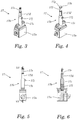
- FIG. 3 the component receptacle 17 is shown in more detail.
- the sleeve assembly 17b consists of an outer sleeve 17c and an inner sleeve 17d, in which in.
- an index pin 17e is inserted.
- a detection pin 17f 17e is inserted into the telescopic sleeve assembly 17b instead of the index pin.
- the variant with the index pin is used for accurate positioning of the component, wherein the index pin engages in an opening or depression on the underside of the component 13. If the detection pin 17f inserted into the telescopic sleeve assembly 17b, so the position of the component holder 17 can be accurately determined or precisely defined. Without index pin 17e or detection pin 17f is the flat top of the inner sleeve 17d in the example shown as a component support.
- the positioning of the component holder 17 takes place by means of the inserted detection pin 17f as follows:
- the laser is positioned on the base plate 16 by means of the drives 14 and 15 at the desired position of the respective component holder.
- the operating personnel then positioned the component holder 17 with inserted detection pin 17f roughly below the laser beam 24.
- For the fine positioning of the detection pin 17f on its upper side a flat disc 17g and a central bore 17h.
- the laser beam 24 strikes the flat disk 17g, the reflection of the laser beam 24 can be detected by the detector arranged in the application head 23.
- the intensity of the reflected light decreases drastically, which is detected by the evaluation electronics and signaled to the operating personnel as reaching the desired position, so that the component holder can be fixed at this position by means of a magnetic base.
- the identification pins are replaced by index pins or the detection pins are removed so that the component holders act as component supports.
- the procedure is correspondingly reversed: after the component 13 has been arranged in the desired manner by means of the component holders 17-20 on the base plate 16, the component holders are obtained 17 - 20 fixed on the base plate. Subsequently, the component to be coated 13 is removed and used detection pins in the component holders. Then, the laser beam 24 is controlled via the drive means 14 and 15 so that the laser beam 24 hits exactly in the bore of the respective component receiving. These positions are stored as nominal positions of the respective component receptacle 17-20.
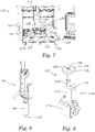
- FIGS. 5 and 6 is the component holder 17 of FIG. 3 in the side view or in a cross section along the line VI-VI of FIG. 5 shown.
- the inner sleeve 17d is loaded upward by means of a spring 17i and can be fixed by means of a knurled screw 17j.
- the index pin 17e is thus pressed upward over the spring-loaded inner sleeve 17d until the upper side of the component 13 comes into abutment against the lower edges 21a and 22a of the gauges 21 and 21, respectively.
- the height of the component at different positions along the contour of the top of the component can be precisely determined.
- the position of the slidable inner sleeve 17d of the telescopic sleeve assembly 17b is fixed by tightening the knurled screw 17j.
- FIGS. 7 to 12 a second variant of the coating system according to the invention is described in more detail. Elements which fulfill the same or similar function as elements already described in connection with the first embodiment of the Figures 1-6 are described below, with the same, but increased by 100 reference numeral and not further explained.
- FIG. 7 One recognizes a coating system 110, in which again a fluid is applied to the surface 112 of a component 113 with a movable dosing tip 111. It again recognizes two component receptacles 117, 118 in the foreground, on which the component 113 is mounted, wherein the component receptacles 117, 118 are each again positioned with magnetic feet 117a, 118a on a ferromagnetic base plate 116.
- the applicator head 123 of the second embodiment has a mechanical position sensor 125.
- the mechanical position sensor 125 serves both for detecting the target positions of the component holders during the initial setup a component to be coated, as well as for the display of the desired positions in the re-establishment of the component receptacles after a component change.
- the mechanical position sensor 125 has a sensor head 126, from the underside of which a movable pin 127 protrudes.
- a position sensor located in the interior of the sensor head 126 is designed so that at least three states of the pin 127 can be distinguished, namely a retracted position in which the pin is completely or almost completely pushed back into the interior of the sensor head, a partially extended position and a fully extended position in which the pin is extended out of the housing to a predetermined maximum length.
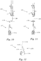
- the component holder is provided with a detection pin, which in the variant of FIGS. 7 to 12 is formed as a centering plate 117k.
- a detection pin which in the variant of FIGS. 7 to 12 is formed as a centering plate 117k.
- An exemplary component receptacle 117 with the centering plate 117k is shown in FIG FIG. 9 shown.
- a magnetic base 117a carrying a telescopically extendable sleeve assembly 117b.
- the sleeve assembly 117b consists of an outer sleeve 117c and an inner sleeve 117d. In the in FIG.
- the recognition plate 117k is used.
- the centering plate 117k has an opening 128, the underside of which is closed by a bottom 129.
- the inner diameter of the opening 128 is slightly larger than the outer diameter of the pin 127 of the mechanical position sensor 125, so that the pin 127 can engage in the opening 128, while other parts of the sensor head 126 of the mechanical position sensor 125 can not engage in the opening 128.
- the depth of the opening 128, that is, the distance of the top of the bottom plate 129 from the top of the centering plate 117k, is smaller than the maximum extension distance of the pin 127 from the sensor head 126.
- a rocker arm 117I is provided for fixing the height of the telescopically extendable sleeve assembly 117b instead of a thumbscrew, which defines the inner sleeve 117d in the desired position with respect to the outer sleeve 117c.
- the mechanical position sensor 125 cooperates with the centering plate 117k fastened in a component receptacle 117.
- the mechanical position sensor 125 has been computer-controlled placed at a predetermined location at which the component receptacle 117 is to be positioned.
- the operator picks up a component receptacle provided with a centering plate 117k and positions it with the magnetic base 117a under the mechanical position sensor 125 FIG. 10 shown position, the component holder is still next to the predetermined target position.
- the pin 127 protrudes maximally from the sensor head 126, so that the operator is signaled that the component holder is not yet in its intended position.
- the pin 127 comes against the surface 130 of the centering plate 117k in abutment and is completely pushed by the plate 117k in the sensor head 126. Also in this position, the operator is signaled that the component holder 117 is not yet at its intended location. Only when the component receptacle 117, as in FIG. 11 is located centrally below the detection pin 127, the detection pin can engage in the opening 128 of the centering plate 117k and assumes a partially extended position. In this position, for example, the operating personnel is visually and / or acoustically signaled that the component receptacle 117 is at its intended position. By switching on the magnetic foot 117a, the operator can then lock the component holder at the intended location.
- FIG. 12 Finally, it is indicated how the component receptacle 117 is converted so that the component 113 to be coated can be arranged on the component receptacle can.
- the in FIG. 12 already removed centering plate 117k removed and replaced by an index pin 117e.
- the index pin 117e is inserted into the inner sleeve 117d of the telescopically extendable sleeve arrangement 117b.
Landscapes
- Coating Apparatus (AREA)
- Engineering & Computer Science (AREA)
- Robotics (AREA)
Claims (12)
- Procédé d'application d'un fluide à la surface (12, 112) d'un composant (13), le composant (13, 113) étant disposé sur plusieurs organes de réception de composant (17, 18, 19, 20, 117, 118) dans une installation de revêtement (10) commandée par ordinateur, la position du composant (13, 113) étant saisie et le fluide étant appliqué sur la surface (12, 112) du composant (13, 113) selon un déroulement préprogrammé de l'application du revêtement, au moins un des organes de réception de composant (17, 18, 19, 20, 117, 118) étant monté sur une plaque de base (16, 116) de manière à pouvoir être positionné librement,
caractérisé en ce que la disposition et la saisie de la position du composant (13, 113) sont effectuées dans l'installation de revêtement (10) en disposant les organes de réception de composant (17, 18, 19, 20, 117, 118) à des endroits prédéterminés sur la plaque de base (16, 116). - Procédé selon la revendication 1, caractérisé en ce que l'on dispose le composant (13, 13) dans l'installation de revêtement à l'aide de trois à cinq organes de réception de composant (17, 18, 19, 20, 117, 118).
- Procédé selon l'une des revendications 1 ou 2, caractérisé en ce qu'au moins un des organes de réception de composant (17, 18, 19, 20, 117, 118) est réglable en hauteur.
- Procédé selon l'une des revendications 1 à 3, caractérisé en ce que les organes de réception de composant (17, 18, 19, 20, 117, 118) adaptés pour pouvoir être disposés librement, sont configurés pour pouvoir être fixés sur la p laque de base (16, 116) à l'aide de pieds magnétiques (17a, 18a, 19a, 20a, 117a, 118a).
- Procédé selon l'une des revendications 1 à 4, caractérisé en ce que les organes de réception de composant (17, 18, 19, 20, 117, 118) comprennent des parties de tête (17e, 17f, 117e, 117k) remplaçables.
- Procédé selon l'une des revendications 1 à 5, caractérisé en ce que les endroits prédéterminés pour les organes de réception de composant (17, 18, 19, 20) sont indiqués par un faisceau laser (24).
- Procédé selon l'une des revendications 1 à 5, caractérisé en ce que les endroits prédéterminés pour les organes de réception de composant (117, 118) sont indiqués par un capteur de position (125) mécanique.
- Procédé selon l'une des revendications 1 à 7, caractérisé en ce que l'on détermine les endroits prédéterminés pour les organes de réception de composant (17, 18, 19, 20, 117, 118) lors de la première préparation au fonctionnement de l'installation de revêtement pour un nouveau composant (13, 113) et l'on les met en mémoire dans l'installation de revêtement (10, 110).
- Procédé selon la revendication 8, caractérisé en ce que, lors de la première préparation au fonctionnement de l'installation de revêtement pour un nouveau composant (13, 113), l'on dispose et oriente le composant librement dans l'installation de revêtement (10, 110) et l'on saisit et met en mémoire les positions des organes de réception de composant (17, 18, 19, 20, 117, 118).
- Installation de revêtement (10, 110) commandée par ordinateur pour l'application d'un fluide sur une surface (12, 112) d'un composant (13, 113), avecau moins une plaque de base (16, 116) sur laquelle plusieurs organes de réception de composant (17, 18, 19, 20, 117, 118) peuvent être positionnés librement,au moins une pointe de dosage mobile (11, 111) pour l'application du fluide sur la surface (12, 112) du composant (13, 113),caractérisée en ce que l'installation de revêtement (10, 110) comprend au moins un dispositif pour saisir les positions de consigne des organes de réception de composant (17, 18, 19, 20, 117, 118) et/ou pour l'affichage des positions de consigne des organes de réception de composant (17, 18, 19, 20, 117, 118).
- Installation de revêtement selon la revendication 10, caractérisé en ce que le dispositif pour saisir les positions de consigne des organes de réception de composant (17, 18, 19, 20) et/ou pour l'affichage des positions de consigne des organes de réception de composant (17, 18, 19, 20) comprend un laser (24).
- Installation de revêtement selon la revendication 10, caractérisé en ce que le dispositif pour saisir les positions de consigne des organes de réception de composant (117, 118) et/ou pour l'affichage des positions de consigne des organes de réception de composant (117, 118) comprend un capteur de position (125) mécanique.
Priority Applications (1)
| Application Number | Priority Date | Filing Date | Title |
|---|---|---|---|
| PL15154481T PL2907585T3 (pl) | 2014-02-17 | 2015-02-10 | Sposób nanoszenia płynu na powierzchnię części konstrukcyjnej i odnośne urządzenie |
Applications Claiming Priority (1)
| Application Number | Priority Date | Filing Date | Title |
|---|---|---|---|
| DE102014002127.0A DE102014002127B3 (de) | 2014-02-17 | 2014-02-17 | Verfahren und Vorrichtung zum Auftragen eine Fluids auf eine Oberfläche eines Bauteils |
Publications (2)
| Publication Number | Publication Date |
|---|---|
| EP2907585A1 EP2907585A1 (fr) | 2015-08-19 |
| EP2907585B1 true EP2907585B1 (fr) | 2019-04-03 |
Family
ID=52633052
Family Applications (1)
| Application Number | Title | Priority Date | Filing Date |
|---|---|---|---|
| EP15154481.4A Active EP2907585B1 (fr) | 2014-02-17 | 2015-02-10 | Procédé et dispositif d'application d'un fluide à la surface d'un composant |
Country Status (5)
| Country | Link |
|---|---|
| EP (1) | EP2907585B1 (fr) |
| DE (2) | DE102014002127B3 (fr) |
| ES (1) | ES2732452T3 (fr) |
| HU (1) | HUE045207T2 (fr) |
| PL (1) | PL2907585T3 (fr) |
Cited By (1)
| Publication number | Priority date | Publication date | Assignee | Title |
|---|---|---|---|---|
| DE102021132185A1 (de) | 2021-12-07 | 2023-06-07 | Sener Cicek | Anlage und Verfahren zum Bearbeiten eines Bauteils |
Families Citing this family (12)
| Publication number | Priority date | Publication date | Assignee | Title |
|---|---|---|---|---|
| CN107470068A (zh) * | 2015-11-28 | 2017-12-15 | 裘列秀 | 一种开放式钢体表面维护机器人 |
| CN105479123B (zh) * | 2016-02-04 | 2017-09-22 | 山东富源履带机械有限公司 | 一种箱体加工工装及其加工工艺 |
| TW201815485A (zh) * | 2016-07-26 | 2018-05-01 | 德商開麥妥公司 | 填充密封蓋之裝置與方法 |
| FR3080302B1 (fr) * | 2018-04-20 | 2020-03-20 | Psa Automobiles Sa | Centrage d’une buse d’extrusion au moyen d’un pion fixe |
| CN108514991A (zh) * | 2018-06-07 | 2018-09-11 | 嘉兴爱劳科斯智能照明有限公司 | 一种线路板点胶装置 |
| CN108940672B (zh) * | 2018-07-12 | 2020-05-15 | 安徽贵达汽车部件有限公司 | 一种刹车蹄铁喷胶装置 |
| CN109261396B (zh) * | 2018-08-15 | 2020-11-17 | 宁波雷奥自动化设备有限公司 | 衬套外管全自动内涂胶生产线的移载装置 |
| CN109225720A (zh) * | 2018-10-09 | 2019-01-18 | 王成 | 一种环保型新能源汽车生产加工用表层漆料喷涂辅助设备 |
| CN109865615B (zh) * | 2019-02-20 | 2020-09-04 | 重庆电子工程职业学院 | 一种汽车生产线用锻件涂装设备 |
| CN112844928A (zh) * | 2021-01-10 | 2021-05-28 | 王文 | 一种智能水表加工用喷涂设备及其处理方法 |
| CN113769977A (zh) * | 2021-09-10 | 2021-12-10 | 浙江大华智联有限公司 | 双轨在线自动点胶机及其控制方法 |
| CN114011665B (zh) * | 2021-11-09 | 2022-10-21 | 山西钢科碳材料有限公司 | 一种用于空气舵的夹具 |
Family Cites Families (4)
| Publication number | Priority date | Publication date | Assignee | Title |
|---|---|---|---|---|
| DE3606495C1 (de) * | 1986-02-28 | 1987-04-30 | Bayerische Motoren Werke Ag | Verfahren und Vorrichtung zum Aufbringen von Klebemittel auf biegeweiche strangfoermige Teile |
| US5614024A (en) * | 1993-08-06 | 1997-03-25 | Hitachi Techno Engineering Co., Ltd. | Apparatus for applying paste |
| US8911282B2 (en) * | 2010-12-20 | 2014-12-16 | Progressive Surface, Inc. | Apparatus with variable fixturing arms for abrasive environment |
| ITPI20120062A1 (it) * | 2012-05-21 | 2013-11-22 | Cmo Di Sodini Dino & C S N C | Metodo per la verniciatura di oggetti e apparecchiatura che attua tale metodo |
-
2014
- 2014-02-17 DE DE102014002127.0A patent/DE102014002127B3/de not_active Expired - Fee Related
-
2015
- 2015-02-10 HU HUE15154481A patent/HUE045207T2/hu unknown
- 2015-02-10 DE DE202015009696.4U patent/DE202015009696U1/de active Active
- 2015-02-10 PL PL15154481T patent/PL2907585T3/pl unknown
- 2015-02-10 EP EP15154481.4A patent/EP2907585B1/fr active Active
- 2015-02-10 ES ES15154481T patent/ES2732452T3/es active Active
Non-Patent Citations (1)
| Title |
|---|
| None * |
Cited By (1)
| Publication number | Priority date | Publication date | Assignee | Title |
|---|---|---|---|---|
| DE102021132185A1 (de) | 2021-12-07 | 2023-06-07 | Sener Cicek | Anlage und Verfahren zum Bearbeiten eines Bauteils |
Also Published As
| Publication number | Publication date |
|---|---|
| EP2907585A1 (fr) | 2015-08-19 |
| DE102014002127B3 (de) | 2015-06-03 |
| PL2907585T3 (pl) | 2019-10-31 |
| HUE045207T2 (hu) | 2019-12-30 |
| DE202015009696U1 (de) | 2019-03-19 |
| ES2732452T3 (es) | 2019-11-22 |
Similar Documents
| Publication | Publication Date | Title |
|---|---|---|
| EP2907585B1 (fr) | Procédé et dispositif d'application d'un fluide à la surface d'un composant | |
| DE102005003467B4 (de) | Verfahren und Vorrichtung zur Überprüfung von Spaltmaßen zwischen der Rohkarosserie eines Fahrzeugs und Türen oder Klappen, die an der Karosserie angeschlagen sind | |
| EP3147086B1 (fr) | Automatisation d'operations de robot dans la construction aéronautique | |
| DE102005026654A1 (de) | Vorrichtung und Verfahren zur berührungslosen Vermessung der Geometrie, Raumposition und Raumorientierung von Körpern | |
| DE102016123188A1 (de) | Justierbarer Laderoboter | |
| EP3285061B1 (fr) | Procédé et dispositif de test de dureté | |
| EP3559594A1 (fr) | Dispositif destiné à être utilisé dans une machine-outil à commande numérique conçue pour être employée dans un procédé pour mesurer la machine-outil à commande numérique | |
| WO2010037552A1 (fr) | Outil d'étalonnage, système et procédé d'étalonnage et d'alignement automatiques d'un dispositif de manipulation | |
| EP2942781B1 (fr) | Dispositif pour positionner et orienter un corps a symetrie de rotation | |
| DE102004049332A1 (de) | Verfahren zum automatisierten Positionieren mehrerer Bauteile | |
| DE102007043364B4 (de) | Halterung zur Aufnahme einer Ultraschallquelle | |
| DE102012020172A1 (de) | Verfahren und System zum Montieren von wenigstens zwei Bauteilen | |
| DE10320381B4 (de) | Platinentestvorrichtung mit schrägstehend angetriebenen Kontaktiernadeln | |
| DE20304869U1 (de) | Prüf- und Einstellvorrichtung | |
| DE102014005351A1 (de) | Getriebeprüfvorrichtung | |
| DE102013112188B4 (de) | Verfahren zur Montage von Bauteilen mit Hilfe eines Koordinatenmessgeräts | |
| DE10327479A1 (de) | Einrichtung zur Bestimmung der Position eines Werkstücks und Verfahren dafür unter Verwendung von mindestens einer elektronischen Kamera | |
| DE102008025800B4 (de) | Verfahren und Vorrichtung zur automatisierten Montage von Scheiben in einem Scheibenrahmen einer Karosserie eines Kraftfahrzeugs | |
| AT502410B1 (de) | Vorrichtung zur prüfung von werkstücken | |
| DE102019134764A1 (de) | Prüfvorrichtung sowie Verfahren zur Zustandskontrolle von Vakuumsaugern einer Greifeinrichtung | |
| EP1431705A1 (fr) | Procédé et dispositif pour déterminer la position d'une pièce en utilisant une caméra pivotante | |
| DE102018009718A1 (de) | Vorrichtung und Verfahren zum Kalibrieren elnes Lidarsensors | |
| DE10209616A1 (de) | Verfahren und Vorrichtung zur Befestigung eines Sensors | |
| DE102018206967A1 (de) | Verfahren und vorrichtung zur anordnung von kleindimensionierten bauteilen an baugruppen mit exakter ausrichtung der bauteile an der baugruppe | |
| DE3605110C2 (fr) |
Legal Events
| Date | Code | Title | Description |
|---|---|---|---|
| PUAI | Public reference made under article 153(3) epc to a published international application that has entered the european phase |
Free format text: ORIGINAL CODE: 0009012 |
|
| AK | Designated contracting states |
Kind code of ref document: A1 Designated state(s): AL AT BE BG CH CY CZ DE DK EE ES FI FR GB GR HR HU IE IS IT LI LT LU LV MC MK MT NL NO PL PT RO RS SE SI SK SM TR |
|
| AX | Request for extension of the european patent |
Extension state: BA ME |
|
| 17P | Request for examination filed |
Effective date: 20150810 |
|
| RBV | Designated contracting states (corrected) |
Designated state(s): AL AT BE BG CH CY CZ DE DK EE ES FI FR GB GR HR HU IE IS IT LI LT LU LV MC MK MT NL NO PL PT RO RS SE SI SK SM TR |
|
| GRAP | Despatch of communication of intention to grant a patent |
Free format text: ORIGINAL CODE: EPIDOSNIGR1 |
|
| STAA | Information on the status of an ep patent application or granted ep patent |
Free format text: STATUS: GRANT OF PATENT IS INTENDED |
|
| INTG | Intention to grant announced |
Effective date: 20181008 |
|
| GRAS | Grant fee paid |
Free format text: ORIGINAL CODE: EPIDOSNIGR3 |
|
| GRAA | (expected) grant |
Free format text: ORIGINAL CODE: 0009210 |
|
| STAA | Information on the status of an ep patent application or granted ep patent |
Free format text: STATUS: THE PATENT HAS BEEN GRANTED |
|
| AK | Designated contracting states |
Kind code of ref document: B1 Designated state(s): AL AT BE BG CH CY CZ DE DK EE ES FI FR GB GR HR HU IE IS IT LI LT LU LV MC MK MT NL NO PL PT RO RS SE SI SK SM TR |
|
| REG | Reference to a national code |
Ref country code: GB Ref legal event code: FG4D Free format text: NOT ENGLISH |
|
| REG | Reference to a national code |
Ref country code: CH Ref legal event code: EP Ref country code: AT Ref legal event code: REF Ref document number: 1115074 Country of ref document: AT Kind code of ref document: T Effective date: 20190415 |
|
| REG | Reference to a national code |
Ref country code: DE Ref legal event code: R096 Ref document number: 502015008514 Country of ref document: DE |
|
| REG | Reference to a national code |
Ref country code: IE Ref legal event code: FG4D Free format text: LANGUAGE OF EP DOCUMENT: GERMAN |
|
| REG | Reference to a national code |
Ref country code: NL Ref legal event code: MP Effective date: 20190403 |
|
| REG | Reference to a national code |
Ref country code: LT Ref legal event code: MG4D |
|
| PG25 | Lapsed in a contracting state [announced via postgrant information from national office to epo] |
Ref country code: NL Free format text: LAPSE BECAUSE OF FAILURE TO SUBMIT A TRANSLATION OF THE DESCRIPTION OR TO PAY THE FEE WITHIN THE PRESCRIBED TIME-LIMIT Effective date: 20190403 |
|
| PG25 | Lapsed in a contracting state [announced via postgrant information from national office to epo] |
Ref country code: FI Free format text: LAPSE BECAUSE OF FAILURE TO SUBMIT A TRANSLATION OF THE DESCRIPTION OR TO PAY THE FEE WITHIN THE PRESCRIBED TIME-LIMIT Effective date: 20190403 Ref country code: NO Free format text: LAPSE BECAUSE OF FAILURE TO SUBMIT A TRANSLATION OF THE DESCRIPTION OR TO PAY THE FEE WITHIN THE PRESCRIBED TIME-LIMIT Effective date: 20190703 Ref country code: HR Free format text: LAPSE BECAUSE OF FAILURE TO SUBMIT A TRANSLATION OF THE DESCRIPTION OR TO PAY THE FEE WITHIN THE PRESCRIBED TIME-LIMIT Effective date: 20190403 Ref country code: SE Free format text: LAPSE BECAUSE OF FAILURE TO SUBMIT A TRANSLATION OF THE DESCRIPTION OR TO PAY THE FEE WITHIN THE PRESCRIBED TIME-LIMIT Effective date: 20190403 Ref country code: PT Free format text: LAPSE BECAUSE OF FAILURE TO SUBMIT A TRANSLATION OF THE DESCRIPTION OR TO PAY THE FEE WITHIN THE PRESCRIBED TIME-LIMIT Effective date: 20190803 Ref country code: AL Free format text: LAPSE BECAUSE OF FAILURE TO SUBMIT A TRANSLATION OF THE DESCRIPTION OR TO PAY THE FEE WITHIN THE PRESCRIBED TIME-LIMIT Effective date: 20190403 Ref country code: LT Free format text: LAPSE BECAUSE OF FAILURE TO SUBMIT A TRANSLATION OF THE DESCRIPTION OR TO PAY THE FEE WITHIN THE PRESCRIBED TIME-LIMIT Effective date: 20190403 Ref country code: CZ Free format text: LAPSE BECAUSE OF FAILURE TO SUBMIT A TRANSLATION OF THE DESCRIPTION OR TO PAY THE FEE WITHIN THE PRESCRIBED TIME-LIMIT Effective date: 20190403 |
|
| REG | Reference to a national code |
Ref country code: ES Ref legal event code: FG2A Ref document number: 2732452 Country of ref document: ES Kind code of ref document: T3 Effective date: 20191122 |
|
| PG25 | Lapsed in a contracting state [announced via postgrant information from national office to epo] |
Ref country code: BG Free format text: LAPSE BECAUSE OF FAILURE TO SUBMIT A TRANSLATION OF THE DESCRIPTION OR TO PAY THE FEE WITHIN THE PRESCRIBED TIME-LIMIT Effective date: 20190703 Ref country code: RS Free format text: LAPSE BECAUSE OF FAILURE TO SUBMIT A TRANSLATION OF THE DESCRIPTION OR TO PAY THE FEE WITHIN THE PRESCRIBED TIME-LIMIT Effective date: 20190403 Ref country code: LV Free format text: LAPSE BECAUSE OF FAILURE TO SUBMIT A TRANSLATION OF THE DESCRIPTION OR TO PAY THE FEE WITHIN THE PRESCRIBED TIME-LIMIT Effective date: 20190403 Ref country code: GR Free format text: LAPSE BECAUSE OF FAILURE TO SUBMIT A TRANSLATION OF THE DESCRIPTION OR TO PAY THE FEE WITHIN THE PRESCRIBED TIME-LIMIT Effective date: 20190704 |
|
| REG | Reference to a national code |
Ref country code: HU Ref legal event code: AG4A Ref document number: E045207 Country of ref document: HU |
|
| PG25 | Lapsed in a contracting state [announced via postgrant information from national office to epo] |
Ref country code: IS Free format text: LAPSE BECAUSE OF FAILURE TO SUBMIT A TRANSLATION OF THE DESCRIPTION OR TO PAY THE FEE WITHIN THE PRESCRIBED TIME-LIMIT Effective date: 20190803 |
|
| REG | Reference to a national code |
Ref country code: DE Ref legal event code: R097 Ref document number: 502015008514 Country of ref document: DE |
|
| PG25 | Lapsed in a contracting state [announced via postgrant information from national office to epo] |
Ref country code: RO Free format text: LAPSE BECAUSE OF FAILURE TO SUBMIT A TRANSLATION OF THE DESCRIPTION OR TO PAY THE FEE WITHIN THE PRESCRIBED TIME-LIMIT Effective date: 20190403 Ref country code: SK Free format text: LAPSE BECAUSE OF FAILURE TO SUBMIT A TRANSLATION OF THE DESCRIPTION OR TO PAY THE FEE WITHIN THE PRESCRIBED TIME-LIMIT Effective date: 20190403 Ref country code: EE Free format text: LAPSE BECAUSE OF FAILURE TO SUBMIT A TRANSLATION OF THE DESCRIPTION OR TO PAY THE FEE WITHIN THE PRESCRIBED TIME-LIMIT Effective date: 20190403 Ref country code: DK Free format text: LAPSE BECAUSE OF FAILURE TO SUBMIT A TRANSLATION OF THE DESCRIPTION OR TO PAY THE FEE WITHIN THE PRESCRIBED TIME-LIMIT Effective date: 20190403 |
|
| PLBE | No opposition filed within time limit |
Free format text: ORIGINAL CODE: 0009261 |
|
| STAA | Information on the status of an ep patent application or granted ep patent |
Free format text: STATUS: NO OPPOSITION FILED WITHIN TIME LIMIT |
|
| PG25 | Lapsed in a contracting state [announced via postgrant information from national office to epo] |
Ref country code: SM Free format text: LAPSE BECAUSE OF FAILURE TO SUBMIT A TRANSLATION OF THE DESCRIPTION OR TO PAY THE FEE WITHIN THE PRESCRIBED TIME-LIMIT Effective date: 20190403 Ref country code: IT Free format text: LAPSE BECAUSE OF FAILURE TO SUBMIT A TRANSLATION OF THE DESCRIPTION OR TO PAY THE FEE WITHIN THE PRESCRIBED TIME-LIMIT Effective date: 20190403 |
|
| 26N | No opposition filed |
Effective date: 20200106 |
|
| PG25 | Lapsed in a contracting state [announced via postgrant information from national office to epo] |
Ref country code: TR Free format text: LAPSE BECAUSE OF FAILURE TO SUBMIT A TRANSLATION OF THE DESCRIPTION OR TO PAY THE FEE WITHIN THE PRESCRIBED TIME-LIMIT Effective date: 20190403 |
|
| PG25 | Lapsed in a contracting state [announced via postgrant information from national office to epo] |
Ref country code: SI Free format text: LAPSE BECAUSE OF FAILURE TO SUBMIT A TRANSLATION OF THE DESCRIPTION OR TO PAY THE FEE WITHIN THE PRESCRIBED TIME-LIMIT Effective date: 20190403 |
|
| REG | Reference to a national code |
Ref country code: CH Ref legal event code: PL |
|
| GBPC | Gb: european patent ceased through non-payment of renewal fee |
Effective date: 20200210 |
|
| REG | Reference to a national code |
Ref country code: BE Ref legal event code: MM Effective date: 20200229 |
|
| PG25 | Lapsed in a contracting state [announced via postgrant information from national office to epo] |
Ref country code: MC Free format text: LAPSE BECAUSE OF FAILURE TO SUBMIT A TRANSLATION OF THE DESCRIPTION OR TO PAY THE FEE WITHIN THE PRESCRIBED TIME-LIMIT Effective date: 20190403 Ref country code: LU Free format text: LAPSE BECAUSE OF NON-PAYMENT OF DUE FEES Effective date: 20200210 |
|
| PG25 | Lapsed in a contracting state [announced via postgrant information from national office to epo] |
Ref country code: LI Free format text: LAPSE BECAUSE OF NON-PAYMENT OF DUE FEES Effective date: 20200229 Ref country code: CH Free format text: LAPSE BECAUSE OF NON-PAYMENT OF DUE FEES Effective date: 20200229 |
|
| PG25 | Lapsed in a contracting state [announced via postgrant information from national office to epo] |
Ref country code: GB Free format text: LAPSE BECAUSE OF NON-PAYMENT OF DUE FEES Effective date: 20200210 Ref country code: IE Free format text: LAPSE BECAUSE OF NON-PAYMENT OF DUE FEES Effective date: 20200210 Ref country code: FR Free format text: LAPSE BECAUSE OF NON-PAYMENT OF DUE FEES Effective date: 20200229 |
|
| PG25 | Lapsed in a contracting state [announced via postgrant information from national office to epo] |
Ref country code: BE Free format text: LAPSE BECAUSE OF NON-PAYMENT OF DUE FEES Effective date: 20200229 |
|
| PG25 | Lapsed in a contracting state [announced via postgrant information from national office to epo] |
Ref country code: MT Free format text: LAPSE BECAUSE OF FAILURE TO SUBMIT A TRANSLATION OF THE DESCRIPTION OR TO PAY THE FEE WITHIN THE PRESCRIBED TIME-LIMIT Effective date: 20190403 Ref country code: CY Free format text: LAPSE BECAUSE OF FAILURE TO SUBMIT A TRANSLATION OF THE DESCRIPTION OR TO PAY THE FEE WITHIN THE PRESCRIBED TIME-LIMIT Effective date: 20190403 |
|
| PG25 | Lapsed in a contracting state [announced via postgrant information from national office to epo] |
Ref country code: MK Free format text: LAPSE BECAUSE OF FAILURE TO SUBMIT A TRANSLATION OF THE DESCRIPTION OR TO PAY THE FEE WITHIN THE PRESCRIBED TIME-LIMIT Effective date: 20190403 |
|
| PGFP | Annual fee paid to national office [announced via postgrant information from national office to epo] |
Ref country code: PL Payment date: 20230206 Year of fee payment: 9 |
|
| P01 | Opt-out of the competence of the unified patent court (upc) registered |
Effective date: 20230614 |
|
| PGFP | Annual fee paid to national office [announced via postgrant information from national office to epo] |
Ref country code: ES Payment date: 20240319 Year of fee payment: 10 |
|
| PGFP | Annual fee paid to national office [announced via postgrant information from national office to epo] |
Ref country code: AT Payment date: 20240216 Year of fee payment: 10 |
|
| PGFP | Annual fee paid to national office [announced via postgrant information from national office to epo] |
Ref country code: HU Payment date: 20240206 Year of fee payment: 10 Ref country code: DE Payment date: 20240228 Year of fee payment: 10 |