EP2906887B1 - Appareil frigorifique comprenant une électrovanne - Google Patents
Appareil frigorifique comprenant une électrovanne Download PDFInfo
- Publication number
- EP2906887B1 EP2906887B1 EP13774117.9A EP13774117A EP2906887B1 EP 2906887 B1 EP2906887 B1 EP 2906887B1 EP 13774117 A EP13774117 A EP 13774117A EP 2906887 B1 EP2906887 B1 EP 2906887B1
- Authority
- EP
- European Patent Office
- Prior art keywords
- solenoid valve
- cable
- shell
- magnet valve
- wall
- Prior art date
- Legal status (The legal status is an assumption and is not a legal conclusion. Google has not performed a legal analysis and makes no representation as to the accuracy of the status listed.)
- Active
Links
- 238000001816 cooling Methods 0.000 title claims 5
- 238000003780 insertion Methods 0.000 claims description 6
- 230000037431 insertion Effects 0.000 claims description 6
- 238000005057 refrigeration Methods 0.000 description 8
- 210000002105 tongue Anatomy 0.000 description 8
- 239000003507 refrigerant Substances 0.000 description 5
- 238000009434 installation Methods 0.000 description 4
- 230000000295 complement effect Effects 0.000 description 3
- 239000002991 molded plastic Substances 0.000 description 2
- 239000004033 plastic Substances 0.000 description 2
- XLYOFNOQVPJJNP-UHFFFAOYSA-N water Substances O XLYOFNOQVPJJNP-UHFFFAOYSA-N 0.000 description 2
- 238000004873 anchoring Methods 0.000 description 1
- 238000010276 construction Methods 0.000 description 1
- 238000011900 installation process Methods 0.000 description 1
- 239000007787 solid Substances 0.000 description 1
Images

Classifications
-
- F—MECHANICAL ENGINEERING; LIGHTING; HEATING; WEAPONS; BLASTING
- F25—REFRIGERATION OR COOLING; COMBINED HEATING AND REFRIGERATION SYSTEMS; HEAT PUMP SYSTEMS; MANUFACTURE OR STORAGE OF ICE; LIQUEFACTION SOLIDIFICATION OF GASES
- F25D—REFRIGERATORS; COLD ROOMS; ICE-BOXES; COOLING OR FREEZING APPARATUS NOT OTHERWISE PROVIDED FOR
- F25D23/00—General constructional features
- F25D23/006—General constructional features for mounting refrigerating machinery components
-
- F—MECHANICAL ENGINEERING; LIGHTING; HEATING; WEAPONS; BLASTING
- F25—REFRIGERATION OR COOLING; COMBINED HEATING AND REFRIGERATION SYSTEMS; HEAT PUMP SYSTEMS; MANUFACTURE OR STORAGE OF ICE; LIQUEFACTION SOLIDIFICATION OF GASES
- F25D—REFRIGERATORS; COLD ROOMS; ICE-BOXES; COOLING OR FREEZING APPARATUS NOT OTHERWISE PROVIDED FOR
- F25D2400/00—General features of, or devices for refrigerators, cold rooms, ice-boxes, or for cooling or freezing apparatus not covered by any other subclass
- F25D2400/40—Refrigerating devices characterised by electrical wiring
Definitions
- the present invention relates to a refrigeration appliance, in particular a domestic refrigeration appliance, which uses at least one solenoid valve to control the refrigerant flow.
- a solenoid valve can serve in a single-circuit refrigeration device to lock in a standstill phase of the compressor and thus to prevent unwanted heat transfer and exchange of refrigerant between condenser and evaporator.
- Solenoid valves are used in a two-or multi-circuit device to selectively supply refrigerant to one of several evaporators.
- US2005 / 0173323 A1 discloses another example of the prior art and shows a refrigerator to the housing of two solenoid valves are attached.
- solenoid valves In a refrigerator, the installation of a solenoid valve in a refrigerator is cumbersome because not only the valve body must be mechanically fixed, but soldered pipe connections and electrical connections must be contacted.
- the object of the invention is to meet this need.
- the object is achieved by a refrigeration device with the features of claim 1. Since the shell protects the cable from unforeseen stress, a strain relief is no longer necessary, and the conventionally associated costs continue to fall. A confusion of cables during assembly is due to their lengths locked out. Although the second cable can first be incorrectly mounted on the first solenoid valve, but this error falls at the latest when a contacting of the second solenoid valve is impossible.
- the necessary electrical contacts of the cable can be made to the connector and the solenoid valve outside of the refrigerator housing, which further simplifies the installation process.
- the shell has at least one latching contour which can be latched by being plugged in the direction of insertion of the connector on the housing of the refrigerator, a single handle is sufficient to contact the connectors together and at the same time to secure the shell to the housing.
- the shell preferably has at least one elastic latching hook, which acts on the solenoid valve. So it is sufficient for the anchoring of the solenoid valve to push it into the designated slot in the shell. The effort conventionally associated with the tightening of the solenoid valve is eliminated. Since the shell is a relatively small-sized part and can be made inexpensively from plastic, it is possible with relatively little effort to adapt their shape to that of the solenoid valve that a secure locking is possible.
- the cable may conveniently be fixed between the first connector and the solenoid valve at least at one point of the shell to ensure that it is completely covered by the shell after insertion from the solenoid valve and shell into the refrigerator and thus protected from contact.
- the cables connecting the first and second solenoid valves to the first connector are preferably preassembled on the first connector and are first plugged into the assembly of the refrigerator or the assembly to be mounted therein with the solenoid valves.
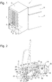
- Fig. 1 shows a perspective view of a household refrigerator according to the present invention. Shown here is a combination refrigerator with a
- Housing 1 comprising a body 2 with two refrigerators, typically a normal refrigerated compartment and a freezer compartment, and two doors 3, 4 for closing the normal refrigeration compartment or the freezer compartment.
- a machine room 5 is recessed near the bottom, in which a compressor 6 is housed in the usual way.
- the compressor 6 feeds compressed refrigerant a condenser 7, which is here shown plate-shaped and mounted on the rear wall of the body 2 above the engine room 5, but could find space in a more compact design in the engine room 5 itself.
- a solenoid valve assembly 8 is connected, the construction and mounting in the engine room 5 on the basis of Fig. 2 to 4 will be explained in more detail.
- the solenoid valve assembly 8 includes one or more solenoid valves that control the distribution of condensed refrigerant in the condenser 7 on (not shown) evaporator of the normal refrigeration compartment and the freezer compartment.
- the solenoid valve assembly is mounted in a corner bounded by a sidewall and ceiling of the engine room 5 (and therefore largely obscured), but it is understood that basically any solid surface of the engine room 5, and in particular a rear wall 9 thereof, for mounting the solenoid valve assembly 8 can be considered.
- Fig. 2 shows the solenoid valve assembly 8 in an enlarged perspective view. It comprises a molded plastic one-piece shell 10, which has slots for two solenoid valves 11, 12 in its interior.
- the solenoid valves 11, 12 here have a substantially cuboidal body, and on two opposite walls 13, 14 of the shell 10 are each elastically deflectable tongues 15th cut free, carry the locking hooks 16 projecting into the interior of the shell.
- the latching hooks 16 have chamfered end surfaces, which are initially deflected elastically when the solenoid valves 11, 12 are pushed into their slots, in order subsequently to encompass one edge of the body of the solenoid valves 12, 13 and thus fix the solenoid valves 12, 13 in a form-fitting manner in the shell 10 , Further into the interior of the shell 10 projecting locking hooks 17 serve to secure pipe connections 18 of the solenoid valves.
- a connector 19 is anchored in a recess of the wall 14. Of the four poles of the connector 19, two are each associated with the solenoid valves 11 and the solenoid valve 12 and connected via a cable 20 or 21 with the respective solenoid valve 11 and 12 respectively.
- the cables 20, 21 are pre-assembled on the connector 19 to be inserted together with this in the recess of the wall 14. At their ends remote from the connector 19, the cables 20, 21 each carry two plug-in shoes for attachment to plate-shaped contacts of the solenoid valves 11, 12, which are hidden here in housing projections 22 of the solenoid valves 11, 12.
- the cables 20, 21 are clamped.
- the cables 20, 21 are fixed substantially immovably over their entire length, and there is no danger that, if the assembly of the Fig. 2 mounted in the refrigerator, a cable protrudes unprotected from the shell 10 or between the walls of the shell 10 and the wall of the engine room 5 is clamped.
- the length of the cables 20, 21 is dimensioned so that when the connector 19 is mounted in its recess, not far from a side facing away from the solenoid valve 12 end wall 25 of the shell 10, only the cable 21 is long enough to contact the solenoid valve 12. Consequently, since there is only one way in which the solenoid valves 11, 12 can be electrically contacted, errors in contacting the solenoid valves 11, 12 are excluded.
- the end wall 25 carries an in Fig. 2 in perspective, in Fig. 3 in a plan view of the end wall shown latching device 26 which serves to anchor the solenoid valve assembly 8 on the refrigerator body 2.
- the latching device 26 has approximately the shape of a cuboid, which is elongated in the insertion direction of the connector 19 and at one of facing away from the shell front end to facilitate insertion into a locking recess of the body 2 is tapered.
- Two side walls of the parallelepiped shape are formed by ribs 27 projecting from the end wall 25 and elongated radially to the insertion direction.
- a latching tongue 28 forms a side facing away from the end wall 25 side of the cuboid.
- the latching tongue 28 is connected only via its front end with the latching device 26 and elastically deflectable into a free space between the ribs 27 inside. At its rear end, the latching tongue 28 carries a projection 29. At one in the perspective of the Fig. 2 facing away from the viewer back of the projection 29, a recess is formed, in which a tool, such as a screwdriver, can be introduced to deflect the latching tongue 28.
- Fig. 3 shows the shell 10 in a plan view of the end wall 25. It can be seen a recess 30 of the end wall, which is provided to receive a pipe of the solenoid valve 11 in the assembled state and the connector 19, which projects beyond the contour of the end wall 25 in part to engage in a complementary connector of the body 2.
- the connector 19 here has a roughly cube-shaped main body 31 made of plastic, projecting from the plurality of sleeves 32, in each of which extends a metallic contact pin.
- a two-armed lever 33 is formed, of which one arm is formed as a barb 34 and the other arm 35 is accessible through a not visible in the figure window of the wall 14 to pivot by the lever 33, the barb 34 of a Detach locking edge of the complementary, body-side connector.
- Fig. 4 shows in a perspective view a section of a molded plastic lining of the engine room 5 with a niche for the solenoid valve assembly 8 in the engine room 5.
- the two outer wall panels 37, 39 each carry two horizontal, mirror image mutually oriented ribs 40. Between the rear wall 9 remote from the ends of the ribs 40 extends a slot 41.
- the middle wall plate 38 is smaller in size than the two outer wall panels 37th , 39, but like the wall plate 39, is provided with ribs 40 and a slot 41 which are mirrored to the corresponding ribs 40 and the slot 41 of the wall plate 37.
- the connector 19 complementary, body-side connector 42 with four sockets 43 and a slot 44 in which the barb 34 is latched.
- the locking means 26 When installing the solenoid valve assembly 8, the locking means 26 are inserted into the formed between the ribs 40 on the wall plates 37, 38 grooves until the tips of the locking devices 26 abut against a stop 45 and the projections 29 of their locking tongues 28 in the slots 41 of the wall panels 37th , 39 engage and the barbs 34 of the connector 19 hooked in the slot 44. Consequently, the shell 10 is anchored at three points on the body 2 and securely fixed. To solve it again, is only possible if at the same time by pressing against the arm 35 of the barb 34 is released and with the aid of a between the wall plates 37, 39 and the end walls 25 of the shell 10 imported tool such as a screwdriver, the projections 29 from the Slits 41 are pulled out.
- the middle wall plate 38 is in the installation of in Fig. 2 shown solenoid valve assembly 8 functionless.
- the purpose of the wall panel 38 is that when the engine room lining of the Fig. 4 is installed in another refrigeration unit model, which requires only one solenoid valve, a solenoid valve assembly from in Fig. 5 shown type with a smaller, only one slot having shell 46 between the wall plates 37, 38 and the connector 42 can be latched.
Landscapes
- Engineering & Computer Science (AREA)
- Chemical & Material Sciences (AREA)
- Combustion & Propulsion (AREA)
- Physics & Mathematics (AREA)
- Mechanical Engineering (AREA)
- Thermal Sciences (AREA)
- General Engineering & Computer Science (AREA)
- Magnetically Actuated Valves (AREA)
- Devices That Are Associated With Refrigeration Equipment (AREA)
- Valve Housings (AREA)
Claims (4)
- Appareil frigorifique comprenant une première électrovanne (11) qui est fixée sur un boîtier (1) de l'appareil frigorifique et est reliée à des raccords électriques (43) du boîtier (1) par l'intermédiaire d'un premier câble (20), une coque (10 ; 46) recouvrant l'électrovanne (11) et le premier câble (20), la coque (10) recouvrant en outre une deuxième électrovanne (12), le premier câble (20) portant un premier connecteur (19), et un deuxième connecteur (42) complémentaire au premier connecteur (19) étant ménagé sur le boîtier (1), la deuxième électrovanne (12) étant reliée au premier connecteur (19) par l'intermédiaire d'un deuxième câble (21), le premier connecteur (19), la coque (10) et les électrovannes (11, 12) étant reliés en un ensemble (8), caractérisé en ce que la coque (10) présente au moins un dispositif d'encliquetage (26) qui est encliquetable sur le boîtier (1) par enfichage du connecteur (19) en direction d'enfichage, et en ce que le premier câble (20) est plus court que le trajet le plus court entre le premier connecteur (19) et la deuxième électrovanne (12).
- Appareil frigorifique selon la revendication 1, caractérisé en ce que la coque présente au moins un crochet d'encliquetage (15) élastique qui a prise sur l'électrovanne (11).
- Appareil frigorifique selon la revendication 1 ou 2, caractérisé en ce que le câble entre le premier connecteur (19) et l'électrovanne (11) est fixé sur la coque (10) à au moins un endroit (24).
- Appareil frigorifique selon les revendications 1, 2 ou 3, caractérisé en ce que le câble (20, 21) est prémonté sur le premier connecteur (19) et est relié par enfichage aux électrovannes (11, 12).
Priority Applications (1)
| Application Number | Priority Date | Filing Date | Title |
|---|---|---|---|
| PL13774117T PL2906887T3 (pl) | 2012-10-10 | 2013-10-02 | Urządzenie chłodzące z zaworem magnetycznym |
Applications Claiming Priority (2)
| Application Number | Priority Date | Filing Date | Title |
|---|---|---|---|
| DE102012218407.4A DE102012218407A1 (de) | 2012-10-10 | 2012-10-10 | Kältegerät mit Magnetventil |
| PCT/EP2013/070537 WO2014056778A1 (fr) | 2012-10-10 | 2013-10-02 | Appareil de froid à électrovanne |
Publications (2)
| Publication Number | Publication Date |
|---|---|
| EP2906887A1 EP2906887A1 (fr) | 2015-08-19 |
| EP2906887B1 true EP2906887B1 (fr) | 2019-04-17 |
Family
ID=49322349
Family Applications (1)
| Application Number | Title | Priority Date | Filing Date |
|---|---|---|---|
| EP13774117.9A Active EP2906887B1 (fr) | 2012-10-10 | 2013-10-02 | Appareil frigorifique comprenant une électrovanne |
Country Status (6)
| Country | Link |
|---|---|
| EP (1) | EP2906887B1 (fr) |
| CN (1) | CN104769372B (fr) |
| DE (1) | DE102012218407A1 (fr) |
| PL (1) | PL2906887T3 (fr) |
| TR (1) | TR201906562T4 (fr) |
| WO (1) | WO2014056778A1 (fr) |
Families Citing this family (2)
| Publication number | Priority date | Publication date | Assignee | Title |
|---|---|---|---|---|
| DE102016225721A1 (de) * | 2016-12-21 | 2018-06-21 | Robert Bosch Gmbh | Ventilvorrichtung |
| DE102020207645A1 (de) * | 2020-06-19 | 2021-12-23 | BSH Hausgeräte GmbH | Haushaltsgerät mit spezifisch im Maschinenraum montierten Elektronikmodul, sowie Montageverfahren |
Citations (2)
| Publication number | Priority date | Publication date | Assignee | Title |
|---|---|---|---|---|
| US20050173323A1 (en) * | 2003-10-28 | 2005-08-11 | Meuleners William J. | Designs for filtration systems within appliances |
| DE102006049385A1 (de) * | 2005-10-21 | 2007-05-24 | Samsung Electronics Co., Ltd., Suwon | Kühlgerät |
Family Cites Families (10)
| Publication number | Priority date | Publication date | Assignee | Title |
|---|---|---|---|---|
| US2727361A (en) * | 1952-12-06 | 1955-12-20 | Admiral Corp | Refrigerator system and assembly |
| JPH06294577A (ja) * | 1993-04-08 | 1994-10-21 | Matsushita Refrig Co Ltd | 冷蔵庫 |
| JPH0763473A (ja) * | 1993-08-26 | 1995-03-10 | Matsushita Refrig Co Ltd | 冷蔵庫 |
| DE10037251A1 (de) * | 2000-07-31 | 2002-02-14 | Bsh Bosch Siemens Hausgeraete | Bistabiles Magnetventil |
| US7568357B2 (en) * | 2005-05-18 | 2009-08-04 | Maytag Corporation | Freeze tolerant waterline valve for a refrigerator |
| MX2009000127A (es) * | 2006-07-06 | 2009-01-26 | Lg Electronics Inc | Refrigerador. |
| CN101688726B (zh) * | 2007-06-25 | 2011-05-04 | Bsh博世和西门子家用器具有限公司 | 制冷设备用的灯/风扇单元 |
| DE102007029177A1 (de) * | 2007-06-25 | 2009-01-08 | BSH Bosch und Siemens Hausgeräte GmbH | Kabeldurchführung für ein Kältegerät |
| DE102011004590A1 (de) * | 2011-02-23 | 2012-08-23 | BSH Bosch und Siemens Hausgeräte GmbH | Kältegerät |
| DE102011004594A1 (de) * | 2011-02-23 | 2012-08-23 | BSH Bosch und Siemens Hausgeräte GmbH | Kältegerät mit Verdichterkondensator |
-
2012
- 2012-10-10 DE DE102012218407.4A patent/DE102012218407A1/de not_active Withdrawn
-
2013
- 2013-10-02 EP EP13774117.9A patent/EP2906887B1/fr active Active
- 2013-10-02 WO PCT/EP2013/070537 patent/WO2014056778A1/fr not_active Ceased
- 2013-10-02 PL PL13774117T patent/PL2906887T3/pl unknown
- 2013-10-02 CN CN201380053045.9A patent/CN104769372B/zh not_active Expired - Fee Related
- 2013-10-02 TR TR2019/06562T patent/TR201906562T4/tr unknown
Patent Citations (2)
| Publication number | Priority date | Publication date | Assignee | Title |
|---|---|---|---|---|
| US20050173323A1 (en) * | 2003-10-28 | 2005-08-11 | Meuleners William J. | Designs for filtration systems within appliances |
| DE102006049385A1 (de) * | 2005-10-21 | 2007-05-24 | Samsung Electronics Co., Ltd., Suwon | Kühlgerät |
Also Published As
| Publication number | Publication date |
|---|---|
| WO2014056778A1 (fr) | 2014-04-17 |
| CN104769372B (zh) | 2016-11-09 |
| TR201906562T4 (tr) | 2019-05-21 |
| PL2906887T3 (pl) | 2019-09-30 |
| CN104769372A (zh) | 2015-07-08 |
| EP2906887A1 (fr) | 2015-08-19 |
| DE102012218407A1 (de) | 2014-04-24 |
Similar Documents
| Publication | Publication Date | Title |
|---|---|---|
| EP2010841A2 (fr) | Appareil ménager en plusieurs parties | |
| EP1060539B1 (fr) | Appareil menager | |
| EP2906887B1 (fr) | Appareil frigorifique comprenant une électrovanne | |
| EP2678624B1 (fr) | Appareil électroménager | |
| DE102020210278A1 (de) | Haushaltsgerät mit einer Kamera und einem damit verbundenen Hinterlegteil, sowie Verfahren | |
| EP2492619B1 (fr) | Appareil frigorifique | |
| EP2808632B1 (fr) | Appareil frigorifique doté d'un boîtier électronique | |
| EP2206420A1 (fr) | Panneau de commande pour un appareil electrique | |
| CA2940741C (fr) | Appareil de mesure de centre et dispositif de douille et methode d'assemblage d'un dispositif de douille associe | |
| EP1957897B1 (fr) | Système modulaire de blocs de composants de fonction pour un réfrigérateur et/ou un congélateur et réfrigérateur et/ou congélateur muni d'un système modulaire desdits blocs de composants | |
| DE102012209726A1 (de) | Kältegerät und Verfahren zu seiner Herstellung | |
| WO2008055818A2 (fr) | Bâti d'appareil ménager | |
| WO2017036782A1 (fr) | Appareil frigorifique, notamment appareil électroménager frigorifique, et procédé de fabrication correspondant | |
| DE102013221297A1 (de) | Haushaltsgerät mit Elektronikmodul | |
| DE102021200493A1 (de) | Montageverfahren einer Kamera an einer Innenbehälterwand eines Haushaltsgeräts, sowie Haushaltsgerät | |
| DE102009002041A1 (de) | Kältegerät mit abgedecktem Maschinenraum | |
| EP2476982B1 (fr) | Appareil frigorifique doté d'un composant enclenché dans une paroi extérieure | |
| WO2019068527A1 (fr) | Réfrigérateur domestique pourvu d'une fixation spécifique d'un couvercle pour recouvrir une pièce arrière | |
| EP3462549A1 (fr) | Prise d'appareil permettant d'insérer un boîtier d'appareil, système de raccordement d'appareils et appareil électrique | |
| DE102009045342A1 (de) | Kältegerät mit Ventilator | |
| DE102016224019A1 (de) | Haushaltskältegerät mit spezifischer Erdungsverbindung | |
| EP1006325B1 (fr) | Appareil frigorifique | |
| DE102014206948A1 (de) | Haushaltskältegerät | |
| DE102012208984A1 (de) | Kältegerät mit einer Tragschiene | |
| EP2607825A2 (fr) | Combinaison d'appareils ménagers |
Legal Events
| Date | Code | Title | Description |
|---|---|---|---|
| PUAI | Public reference made under article 153(3) epc to a published international application that has entered the european phase |
Free format text: ORIGINAL CODE: 0009012 |
|
| 17P | Request for examination filed |
Effective date: 20150511 |
|
| AK | Designated contracting states |
Kind code of ref document: A1 Designated state(s): AL AT BE BG CH CY CZ DE DK EE ES FI FR GB GR HR HU IE IS IT LI LT LU LV MC MK MT NL NO PL PT RO RS SE SI SK SM TR |
|
| AX | Request for extension of the european patent |
Extension state: BA ME |
|
| DAX | Request for extension of the european patent (deleted) | ||
| STAA | Information on the status of an ep patent application or granted ep patent |
Free format text: STATUS: EXAMINATION IS IN PROGRESS |
|
| 17Q | First examination report despatched |
Effective date: 20180625 |
|
| GRAP | Despatch of communication of intention to grant a patent |
Free format text: ORIGINAL CODE: EPIDOSNIGR1 |
|
| STAA | Information on the status of an ep patent application or granted ep patent |
Free format text: STATUS: GRANT OF PATENT IS INTENDED |
|
| INTG | Intention to grant announced |
Effective date: 20181123 |
|
| GRAS | Grant fee paid |
Free format text: ORIGINAL CODE: EPIDOSNIGR3 |
|
| GRAA | (expected) grant |
Free format text: ORIGINAL CODE: 0009210 |
|
| STAA | Information on the status of an ep patent application or granted ep patent |
Free format text: STATUS: THE PATENT HAS BEEN GRANTED |
|
| AK | Designated contracting states |
Kind code of ref document: B1 Designated state(s): AL AT BE BG CH CY CZ DE DK EE ES FI FR GB GR HR HU IE IS IT LI LT LU LV MC MK MT NL NO PL PT RO RS SE SI SK SM TR |
|
| REG | Reference to a national code |
Ref country code: GB Ref legal event code: FG4D Free format text: NOT ENGLISH |
|
| REG | Reference to a national code |
Ref country code: CH Ref legal event code: EP |
|
| REG | Reference to a national code |
Ref country code: DE Ref legal event code: R096 Ref document number: 502013012663 Country of ref document: DE |
|
| REG | Reference to a national code |
Ref country code: AT Ref legal event code: REF Ref document number: 1122000 Country of ref document: AT Kind code of ref document: T Effective date: 20190515 Ref country code: IE Ref legal event code: FG4D Free format text: LANGUAGE OF EP DOCUMENT: GERMAN |
|
| REG | Reference to a national code |
Ref country code: NL Ref legal event code: MP Effective date: 20190417 |
|
| REG | Reference to a national code |
Ref country code: LT Ref legal event code: MG4D |
|
| PG25 | Lapsed in a contracting state [announced via postgrant information from national office to epo] |
Ref country code: NL Free format text: LAPSE BECAUSE OF FAILURE TO SUBMIT A TRANSLATION OF THE DESCRIPTION OR TO PAY THE FEE WITHIN THE PRESCRIBED TIME-LIMIT Effective date: 20190417 |
|
| PG25 | Lapsed in a contracting state [announced via postgrant information from national office to epo] |
Ref country code: AL Free format text: LAPSE BECAUSE OF FAILURE TO SUBMIT A TRANSLATION OF THE DESCRIPTION OR TO PAY THE FEE WITHIN THE PRESCRIBED TIME-LIMIT Effective date: 20190417 Ref country code: PT Free format text: LAPSE BECAUSE OF FAILURE TO SUBMIT A TRANSLATION OF THE DESCRIPTION OR TO PAY THE FEE WITHIN THE PRESCRIBED TIME-LIMIT Effective date: 20190817 Ref country code: SE Free format text: LAPSE BECAUSE OF FAILURE TO SUBMIT A TRANSLATION OF THE DESCRIPTION OR TO PAY THE FEE WITHIN THE PRESCRIBED TIME-LIMIT Effective date: 20190417 Ref country code: FI Free format text: LAPSE BECAUSE OF FAILURE TO SUBMIT A TRANSLATION OF THE DESCRIPTION OR TO PAY THE FEE WITHIN THE PRESCRIBED TIME-LIMIT Effective date: 20190417 Ref country code: HR Free format text: LAPSE BECAUSE OF FAILURE TO SUBMIT A TRANSLATION OF THE DESCRIPTION OR TO PAY THE FEE WITHIN THE PRESCRIBED TIME-LIMIT Effective date: 20190417 Ref country code: NO Free format text: LAPSE BECAUSE OF FAILURE TO SUBMIT A TRANSLATION OF THE DESCRIPTION OR TO PAY THE FEE WITHIN THE PRESCRIBED TIME-LIMIT Effective date: 20190717 Ref country code: ES Free format text: LAPSE BECAUSE OF FAILURE TO SUBMIT A TRANSLATION OF THE DESCRIPTION OR TO PAY THE FEE WITHIN THE PRESCRIBED TIME-LIMIT Effective date: 20190417 Ref country code: LT Free format text: LAPSE BECAUSE OF FAILURE TO SUBMIT A TRANSLATION OF THE DESCRIPTION OR TO PAY THE FEE WITHIN THE PRESCRIBED TIME-LIMIT Effective date: 20190417 |
|
| PG25 | Lapsed in a contracting state [announced via postgrant information from national office to epo] |
Ref country code: LV Free format text: LAPSE BECAUSE OF FAILURE TO SUBMIT A TRANSLATION OF THE DESCRIPTION OR TO PAY THE FEE WITHIN THE PRESCRIBED TIME-LIMIT Effective date: 20190417 Ref country code: RS Free format text: LAPSE BECAUSE OF FAILURE TO SUBMIT A TRANSLATION OF THE DESCRIPTION OR TO PAY THE FEE WITHIN THE PRESCRIBED TIME-LIMIT Effective date: 20190417 Ref country code: BG Free format text: LAPSE BECAUSE OF FAILURE TO SUBMIT A TRANSLATION OF THE DESCRIPTION OR TO PAY THE FEE WITHIN THE PRESCRIBED TIME-LIMIT Effective date: 20190717 Ref country code: GR Free format text: LAPSE BECAUSE OF FAILURE TO SUBMIT A TRANSLATION OF THE DESCRIPTION OR TO PAY THE FEE WITHIN THE PRESCRIBED TIME-LIMIT Effective date: 20190718 |
|
| PG25 | Lapsed in a contracting state [announced via postgrant information from national office to epo] |
Ref country code: IS Free format text: LAPSE BECAUSE OF FAILURE TO SUBMIT A TRANSLATION OF THE DESCRIPTION OR TO PAY THE FEE WITHIN THE PRESCRIBED TIME-LIMIT Effective date: 20190817 |
|
| REG | Reference to a national code |
Ref country code: DE Ref legal event code: R097 Ref document number: 502013012663 Country of ref document: DE |
|
| PG25 | Lapsed in a contracting state [announced via postgrant information from national office to epo] |
Ref country code: CZ Free format text: LAPSE BECAUSE OF FAILURE TO SUBMIT A TRANSLATION OF THE DESCRIPTION OR TO PAY THE FEE WITHIN THE PRESCRIBED TIME-LIMIT Effective date: 20190417 Ref country code: RO Free format text: LAPSE BECAUSE OF FAILURE TO SUBMIT A TRANSLATION OF THE DESCRIPTION OR TO PAY THE FEE WITHIN THE PRESCRIBED TIME-LIMIT Effective date: 20190417 Ref country code: DK Free format text: LAPSE BECAUSE OF FAILURE TO SUBMIT A TRANSLATION OF THE DESCRIPTION OR TO PAY THE FEE WITHIN THE PRESCRIBED TIME-LIMIT Effective date: 20190417 Ref country code: EE Free format text: LAPSE BECAUSE OF FAILURE TO SUBMIT A TRANSLATION OF THE DESCRIPTION OR TO PAY THE FEE WITHIN THE PRESCRIBED TIME-LIMIT Effective date: 20190417 Ref country code: SK Free format text: LAPSE BECAUSE OF FAILURE TO SUBMIT A TRANSLATION OF THE DESCRIPTION OR TO PAY THE FEE WITHIN THE PRESCRIBED TIME-LIMIT Effective date: 20190417 |
|
| PLBE | No opposition filed within time limit |
Free format text: ORIGINAL CODE: 0009261 |
|
| STAA | Information on the status of an ep patent application or granted ep patent |
Free format text: STATUS: NO OPPOSITION FILED WITHIN TIME LIMIT |
|
| PG25 | Lapsed in a contracting state [announced via postgrant information from national office to epo] |
Ref country code: IT Free format text: LAPSE BECAUSE OF FAILURE TO SUBMIT A TRANSLATION OF THE DESCRIPTION OR TO PAY THE FEE WITHIN THE PRESCRIBED TIME-LIMIT Effective date: 20190417 Ref country code: SM Free format text: LAPSE BECAUSE OF FAILURE TO SUBMIT A TRANSLATION OF THE DESCRIPTION OR TO PAY THE FEE WITHIN THE PRESCRIBED TIME-LIMIT Effective date: 20190417 |
|
| 26N | No opposition filed |
Effective date: 20200120 |
|
| PG25 | Lapsed in a contracting state [announced via postgrant information from national office to epo] |
Ref country code: MC Free format text: LAPSE BECAUSE OF FAILURE TO SUBMIT A TRANSLATION OF THE DESCRIPTION OR TO PAY THE FEE WITHIN THE PRESCRIBED TIME-LIMIT Effective date: 20190417 Ref country code: SI Free format text: LAPSE BECAUSE OF FAILURE TO SUBMIT A TRANSLATION OF THE DESCRIPTION OR TO PAY THE FEE WITHIN THE PRESCRIBED TIME-LIMIT Effective date: 20190417 |
|
| REG | Reference to a national code |
Ref country code: CH Ref legal event code: PL |
|
| PG25 | Lapsed in a contracting state [announced via postgrant information from national office to epo] |
Ref country code: LI Free format text: LAPSE BECAUSE OF NON-PAYMENT OF DUE FEES Effective date: 20191031 Ref country code: CH Free format text: LAPSE BECAUSE OF NON-PAYMENT OF DUE FEES Effective date: 20191031 Ref country code: LU Free format text: LAPSE BECAUSE OF NON-PAYMENT OF DUE FEES Effective date: 20191002 |
|
| REG | Reference to a national code |
Ref country code: BE Ref legal event code: MM Effective date: 20191031 |
|
| PG25 | Lapsed in a contracting state [announced via postgrant information from national office to epo] |
Ref country code: BE Free format text: LAPSE BECAUSE OF NON-PAYMENT OF DUE FEES Effective date: 20191031 |
|
| GBPC | Gb: european patent ceased through non-payment of renewal fee |
Effective date: 20191002 |
|
| PG25 | Lapsed in a contracting state [announced via postgrant information from national office to epo] |
Ref country code: FR Free format text: LAPSE BECAUSE OF NON-PAYMENT OF DUE FEES Effective date: 20191031 Ref country code: GB Free format text: LAPSE BECAUSE OF NON-PAYMENT OF DUE FEES Effective date: 20191002 Ref country code: IE Free format text: LAPSE BECAUSE OF NON-PAYMENT OF DUE FEES Effective date: 20191002 |
|
| REG | Reference to a national code |
Ref country code: AT Ref legal event code: MM01 Ref document number: 1122000 Country of ref document: AT Kind code of ref document: T Effective date: 20191002 |
|
| PG25 | Lapsed in a contracting state [announced via postgrant information from national office to epo] |
Ref country code: AT Free format text: LAPSE BECAUSE OF NON-PAYMENT OF DUE FEES Effective date: 20191002 |
|
| PG25 | Lapsed in a contracting state [announced via postgrant information from national office to epo] |
Ref country code: CY Free format text: LAPSE BECAUSE OF FAILURE TO SUBMIT A TRANSLATION OF THE DESCRIPTION OR TO PAY THE FEE WITHIN THE PRESCRIBED TIME-LIMIT Effective date: 20190417 |
|
| PG25 | Lapsed in a contracting state [announced via postgrant information from national office to epo] |
Ref country code: MT Free format text: LAPSE BECAUSE OF FAILURE TO SUBMIT A TRANSLATION OF THE DESCRIPTION OR TO PAY THE FEE WITHIN THE PRESCRIBED TIME-LIMIT Effective date: 20190417 Ref country code: HU Free format text: LAPSE BECAUSE OF FAILURE TO SUBMIT A TRANSLATION OF THE DESCRIPTION OR TO PAY THE FEE WITHIN THE PRESCRIBED TIME-LIMIT; INVALID AB INITIO Effective date: 20131002 |
|
| PG25 | Lapsed in a contracting state [announced via postgrant information from national office to epo] |
Ref country code: MK Free format text: LAPSE BECAUSE OF FAILURE TO SUBMIT A TRANSLATION OF THE DESCRIPTION OR TO PAY THE FEE WITHIN THE PRESCRIBED TIME-LIMIT Effective date: 20190417 |
|
| PGFP | Annual fee paid to national office [announced via postgrant information from national office to epo] |
Ref country code: TR Payment date: 20220923 Year of fee payment: 10 |
|
| PGFP | Annual fee paid to national office [announced via postgrant information from national office to epo] |
Ref country code: PL Payment date: 20220921 Year of fee payment: 10 |
|
| PGFP | Annual fee paid to national office [announced via postgrant information from national office to epo] |
Ref country code: DE Payment date: 20221031 Year of fee payment: 10 |
|
| REG | Reference to a national code |
Ref country code: DE Ref legal event code: R119 Ref document number: 502013012663 Country of ref document: DE |
|
| PG25 | Lapsed in a contracting state [announced via postgrant information from national office to epo] |
Ref country code: DE Free format text: LAPSE BECAUSE OF NON-PAYMENT OF DUE FEES Effective date: 20240501 |
|
| PG25 | Lapsed in a contracting state [announced via postgrant information from national office to epo] |
Ref country code: PL Free format text: LAPSE BECAUSE OF NON-PAYMENT OF DUE FEES Effective date: 20231002 |