EP2905612B1 - Apparatus for measuring amount of hydrogen penetrated into metal - Google Patents
Apparatus for measuring amount of hydrogen penetrated into metal Download PDFInfo
- Publication number
- EP2905612B1 EP2905612B1 EP12886067.3A EP12886067A EP2905612B1 EP 2905612 B1 EP2905612 B1 EP 2905612B1 EP 12886067 A EP12886067 A EP 12886067A EP 2905612 B1 EP2905612 B1 EP 2905612B1
- Authority
- EP
- European Patent Office
- Prior art keywords
- hydrogen
- cell
- cells
- amount
- corrosion
- Prior art date
- Legal status (The legal status is an assumption and is not a legal conclusion. Google has not performed a legal analysis and makes no representation as to the accuracy of the status listed.)
- Active
Links
Images

Classifications
-
- G—PHYSICS
- G01—MEASURING; TESTING
- G01N—INVESTIGATING OR ANALYSING MATERIALS BY DETERMINING THEIR CHEMICAL OR PHYSICAL PROPERTIES
- G01N17/00—Investigating resistance of materials to the weather, to corrosion, or to light
- G01N17/02—Electrochemical measuring systems for weathering, corrosion or corrosion-protection measurement
-
- G—PHYSICS
- G01—MEASURING; TESTING
- G01N—INVESTIGATING OR ANALYSING MATERIALS BY DETERMINING THEIR CHEMICAL OR PHYSICAL PROPERTIES
- G01N17/00—Investigating resistance of materials to the weather, to corrosion, or to light
- G01N17/006—Investigating resistance of materials to the weather, to corrosion, or to light of metals
-
- G—PHYSICS
- G01—MEASURING; TESTING
- G01N—INVESTIGATING OR ANALYSING MATERIALS BY DETERMINING THEIR CHEMICAL OR PHYSICAL PROPERTIES
- G01N27/00—Investigating or analysing materials by the use of electric, electrochemical, or magnetic means
- G01N27/26—Investigating or analysing materials by the use of electric, electrochemical, or magnetic means by investigating electrochemical variables; by using electrolysis or electrophoresis
- G01N27/28—Electrolytic cell components
- G01N27/30—Electrodes, e.g. test electrodes; Half-cells
- G01N27/304—Gas permeable electrodes
-
- G—PHYSICS
- G01—MEASURING; TESTING
- G01N—INVESTIGATING OR ANALYSING MATERIALS BY DETERMINING THEIR CHEMICAL OR PHYSICAL PROPERTIES
- G01N27/00—Investigating or analysing materials by the use of electric, electrochemical, or magnetic means
- G01N27/26—Investigating or analysing materials by the use of electric, electrochemical, or magnetic means by investigating electrochemical variables; by using electrolysis or electrophoresis
- G01N27/416—Systems
- G01N27/4163—Systems checking the operation of, or calibrating, the measuring apparatus
- G01N27/4165—Systems checking the operation of, or calibrating, the measuring apparatus for pH meters
-
- G—PHYSICS
- G01—MEASURING; TESTING
- G01N—INVESTIGATING OR ANALYSING MATERIALS BY DETERMINING THEIR CHEMICAL OR PHYSICAL PROPERTIES
- G01N33/00—Investigating or analysing materials by specific methods not covered by groups G01N1/00 - G01N31/00
- G01N33/0004—Gaseous mixtures, e.g. polluted air
- G01N33/0009—General constructional details of gas analysers, e.g. portable test equipment
- G01N33/0027—General constructional details of gas analysers, e.g. portable test equipment concerning the detector
- G01N33/0036—General constructional details of gas analysers, e.g. portable test equipment concerning the detector specially adapted to detect a particular component
- G01N33/005—H2
-
- G—PHYSICS
- G01—MEASURING; TESTING
- G01N—INVESTIGATING OR ANALYSING MATERIALS BY DETERMINING THEIR CHEMICAL OR PHYSICAL PROPERTIES
- G01N33/00—Investigating or analysing materials by specific methods not covered by groups G01N1/00 - G01N31/00
- G01N33/20—Metals
- G01N33/202—Constituents thereof
- G01N33/2022—Non-metallic constituents
- G01N33/2025—Gaseous constituents
-
- G—PHYSICS
- G01—MEASURING; TESTING
- G01N—INVESTIGATING OR ANALYSING MATERIALS BY DETERMINING THEIR CHEMICAL OR PHYSICAL PROPERTIES
- G01N27/00—Investigating or analysing materials by the use of electric, electrochemical, or magnetic means
- G01N27/26—Investigating or analysing materials by the use of electric, electrochemical, or magnetic means by investigating electrochemical variables; by using electrolysis or electrophoresis
- G01N27/403—Cells and electrode assemblies
- G01N27/404—Cells with anode, cathode and cell electrolyte on the same side of a permeable membrane which separates them from the sample fluid, e.g. Clark-type oxygen sensors
- G01N27/4045—Cells with anode, cathode and cell electrolyte on the same side of a permeable membrane which separates them from the sample fluid, e.g. Clark-type oxygen sensors for gases other than oxygen
Definitions
- the present invention relates to an apparatus for measuring an amount of hydrogen penetrated into metal, which is capable of accurately measuring an amount of hydrogen penetrating into metal due to the corrosion of the metal.
- Non-patent Literature 1 Non-patent Literature 1
- the "delayed fracture” is a phenomenon that generates sudden brittle fractures in a high strength steel sheet under static load (load stress equal to or smaller than the tensile strength) applied for a certain period of time, without exhibiting hardly any plastic deformation in appearance.
- the delayed fracture herein particularly refers to hydrogen embrittlement induced by hydrogen penetrating into the steel material.
- Hydrogen penetrating into a steel material is considered to be part of hydrogen generated along with the corrosion of the steel sheet.
- various methods of evaluating the delayed fracture focusing on hydrogen penetrating into the steel material have been proposed.
- Patent Literature 1 proposes an evaluation method of delayed fracture characteristics of a steel material by adding diffusible hydrogen to the steel material through cathodic charge so as to measure the limit amount of diffusible hydrogen, in which the steel material is galvanized in order to prevent hydrogen from being discharged from the steel material during the measurement of the limit amount of diffusible hydrogen.
- Patent Literature 1 employs an accelerated test which causes hydrogen to be forced to penetrate into the steel through cathodic charge, and therefore only capable of determining the order of superiority, in terms of susceptibility to delayed fracture, depending on the type of the sample material under conditions different from those of an actual use environment. Accordingly, there cannot be obtained information for determining whether or not an amount of hydrogen that penetrates due to corrosion under an actual use environment causes delayed fracture.
- Non-patent Literature 2 reports on the behavior of hydrogen penetration evaluated with the use of ammonium thiocyanate.
- Non-patent Literature 2 compares the hydrogen penetration observed by using ammonium thiocyanate with the hydrogen penetration caused by cathodic charge.
- Non-patent Literature 2 cannot be considered to be equal to the amount caused by surface corrosion, and thus, it cannot be measured how the behavior of hydrogen penetration is influenced by, for example, zinc coating or the like which is used for the purpose of anti-rust in the field of automobiles in recent years.
- Non-patent Literature 3 reports on a case where high-strength bolts which were left air-exposed and subjected to corrosion for a certain period of time were collected and hydrogen concentrations occluded in the bolts were measured.
- Non-patent Literature 3 also reports on the results of investigating the behavior of hydrogen penetration caused by corrosion resulting from air exposure. The investigation employed an electrochemical hydrogen permeation method, in which test equipment for exposing one surface of a steel sheet to the external environment was used so as to detect the changes in anodic current value from the other surface side of the steel sheet, based on which the behavior of hydrogen penetration was investigated.
- Non-patent Literature 3 the data obtained by the air-exposure test disclosed in Non-patent Literature 3 is merely the test results all obtained under environmental factors associated with a specific geographical environment, and no consideration is given to continuously observing corrosion to be caused under various environments changing along with the traveling of the moving body.
- Non-patent Literature 4 a steel material, which is widely used as an actual material, concerns the most at present as to the problem of delay fracture.
- the problem of delay fracture similarly arises in other metallic materials in the future (see, for example, Non-patent Literature 4).
- Patent Literature 2 the method for measuring the amount of hydrogen penetrated into a metal accompanied by corrosion through electrochemical hydrogen permeation method, in which one side of a specimen is exposed to corrosive environment to be set to the penetration surface of hydrogen produced by corrosive reaction while the other side of the specimen is set to a hydrogen detection surface and, when the flux of hydrogen diffused to the hydrogen detection surface is measured as an anodic current in a state that the potential on the side of the hydrogen detection surface is held to -0.1 to +0.3V vs SCE, an electrochemical cell constituted of a group of a plurality of cells obtained by dividing the electrochemical cell at least in to two is arranged on the side of the hydrogen detection surface of the specimen, the cells in the cell group each being filled with an electrolyte aqueous solution having a pH of 9 to 13 and at least one of the cells serving as a base cell for compensating the residual electric current,
- Patent Literature 2 allows accurate measurement of the amount of hydrogen penetrated into a metal due to corrosion, in consideration of changes in the residual electric current on the anode side resulting from temperature changes in the environment.
- the present invention has an object of providing an apparatus for measuring the amount of hydrogen penetrated into metal, which can be preferably applied to the "method of measuring the amount of hydrogen penetrated into metal" disclosed in Patent Literature 2.
- the apparatus of the present invention is capable of accurately detecting the amount of hydrogen penetrated into metal due to corrosion.
- the use of the apparatus of the present invention allows continuous monitoring of the amount of hydrogen penetrating into a metallic material, the hydrogen being generated due to corrosion occurring at each part of the metallic material constituting a moving body such as automobiles, marine vessels, and rail cars under corrosive environment to which the moving body is exposed during use thereof, to thereby provide information needed for determining whether or not the delayed fracture is to be caused by the amount of hydrogen to penetrate due to corrosion that is to occur under the actual use environment.
- An amount of hydrogen generated due to corrosion of a metallic material and penetrated into a metallic material is measured based on the measurement principle of electrochemical hydrogen permeation, in which a steel sheet surface on the hydrogen penetration surface side is exposed to a corrosion environment so that hydrogen generated due to corrosion penetrates into the steel, and the hydrogen thus penetrated is taken out from the other side, to thereby measure the amount of hydrogen penetrated.
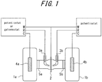
- Non-patent Literature 5 The electrochemical hydrogen permeation was developed by Devanathan and Stachurski in 1962 (Non-patent Literature 5), which uses two electrolysis cells 1 a, 1 b arranged opposite to each other across a sample 2, as schematically illustrated in FIG. 1 .
- the sample surface on the electrolysis cell 1a side on the left is cathode-polarized at a constant potential or at a constant current so as to generate and charge hydrogen.
- the sample 2 is anode-polarized by the electrolysis cell 16 on the right at a constant potential so as to oxidize hydrogen permeated through the sample 2 into hydrogen ions, to thereby obtain the amount of hydrogen thus permeated based on the current value thereof.
- FIG. 1 the sample surface on the electrolysis cell 1a side on the left is cathode-polarized at a constant potential or at a constant current so as to generate and charge hydrogen.
- the sample 2 is anode-polarized by the electrolysis cell 16 on the right at a constant potential so as
- FIG. 1 also illustrates reference electrodes 3a, 3b, and electrodes 4a, 4b.
- the electrode 4b is specifically referred to as counter electrode or coefficient electrode.
- the electrode 4a is connected to a potentiostat for applying a constant potential or a galvanostat for applying a constant current, while the electrode 4b is connected to a potentiostat for applying a constant potential.
- Glass frits 5a, 5b are also provided for removing influence of gas and the like generated by the counter electrodes 4a, 4b.
- Non-patent Literature 3 a surface corresponding to the hydrogen-charging surface is exposed to a corrosive environment
- the anodic current to be measured on the hydrogen detection surface side in the electrochemical hydrogen permeation is superposed with a passive current of the sample material as well as the oxidation current of hydrogen.
- This passive current accounts for the most part of the residual electric current, and is influenced by various factors. In particular, the passive current greatly varies depending on the temperature.
- the anodic current to be measured on the hydrogen detection surface side by the electrochemical hydrogen permeation method is weak, and thus, an accurate anodic current value cannot be obtained unless the temperature dependency of the residual electric current is compensated.
- the electrochemical cell to be provided on the hydrogen detecting surface side is formed of a group of a plurality of cells, obtained by dividing the cell on the same specimen into at least two, at least one of the cells serving as a base cell for compensating the residual electric current, and a protective film for cutting off a contact with a corrosion environment is provided on a region on the hydrogen penetration surface side corresponding to the hydrogen detection region of the base cell, to thereby compensate the temperature dependency of the residual electric current.
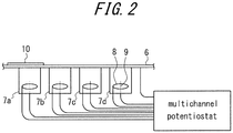
- FIG. 2 schematically illustrates an example of a measuring apparatus of PTL.
- the example of FIG. 2 includes four cells 7a, 7b, 7c, and 7d on the hydrogen detection side of a steel sheet 6 as a specimen, in which the leftmost cell 7a is configured as the base cell for compensating the residual electric current.
- FIG. 2 also illustrates a counter electrode (Pt wire) 8, and a reference electrode (Ir wire) 9. At least two cells are required, preferably without exceeding a maximum of four because too many cells make the handling thereof complicated.
- the surface temperature of the steel sheet in each cell and the temperature of the electrolyte solution in each cell are set to the same temperatures.
- a protective film 10 is provided on the hydrogen penetration surface side of the base cell 7a. The portion thus covered by the protective film 10 is exempted from corrosion, and thus no hydrogen penetrates thereinto. Therefore, the current to be measured on the hydrogen detection surface side of the base cell can be considered as the residual electric current itself.
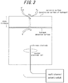
- FIG. 3 schematically illustrates reactions to occur on the corrosive surface (hydrogen penetration surface) side, and on the hydrogen detection surface side in a cell with no protective film (also referred to as channel).
- the surface potential on the hydrogen detection surface side is retained at a potential sufficient enough to cause ionization reaction of hydrogen, so as to take out all the hydrogen reached to the detection surface side through diffusion, as hydrogen ions.
- the steel sheet surface on the hydrogen detection surface side is passivated, and therefore, the anodic current detected on the hydrogen detection side can be considered to substantially correspond to the hydrogen permeation current.
- the current value thus obtained is compensated based on the residual electric current value obtained in the base cell, to thereby obtain an accurate anodic current value irrespective of the changes in residual electric current resulting from temperature changes, with the result that the amount of permeated hydrogen can be accurately calculated based on the anodic current value.
- the solution in the anode electrode chamber needs to be an electrolyte solution having a pH of 9 to 13.
- the reason is as follows. That is, with pH less than 9, the passive state of the steel surface is difficult to maintain at a predetermined potential, whereas with pH exceeding 13, there may be caused great damage to environment in the case of accidental leakage.
- NaOH solution of 0.1 to 0.2 M (mole/liter) is suitably employed as the electrolyte solution with proper pH.
- the electrolyte solution is not necessarily limited to NaOH solution of 0.1 to 0.2 M, and may be any electrolyte solution as long as capable of ensuring the passive state of the steel sheet surface when retaining the steel sheet surface on the hydrogen detection surface side at a potential sufficient enough to cause ionization reaction of hydrogen. Further, it is advantageous to use a gelled electrolyte in place of an electrolyte solution, in terms of preventing leakage as well as ease in handling.
- the hydrogen detection surface needs to be constantly retained at a potential ranged from -0.1 to +0.3V vs SCE. The reason is that the potential of the hydrogen detection surface falling out of the range fails to obtain a stable hydrogen ionization current.
- SCE refers to a saturated calomel electrode
- SHE standard hydrogen electrode
- the reference electrode for controlling the potential various electrodes currently available for practical use can be employed.
- the solution in the anode electrode chamber may be contaminated by chloride ions, which may destroy the passive state on the sample surface to increase the residual electric current, possibly leading to inaccuracy in measured value.
- the reference electrode can eliminate the aforementioned problems, and there have been found out that Ir wire immersed in the solution in the anode electrode chamber makes the reference electrode as Ir/Ir oxide electrode, which allows a stable current to be obtained over a long period. That is, the Ir/Ir oxide electrode is most preferred as the reference electrode, which can stably provide a potential of about -0.04V vs SSE.
- SSE refers to a silver - silver chloride electrode, and the potential of SSE with respect to the standard hydrogen electrode (SHE) is obtained as +0.199V (vs SHE, 25°C).
- the surface of the hydrogen detection surface may preferably be covered with a metal that is high in hydrogen diffusion constant and capable of accelerating the oxidation reaction of hydrogen.
- a metal may include palladium (Pd), a palladium (Pd) alloy, and nickel (Ni).
- the hydrogen detection surface thus covered with such a metal or an alloy is capable of maintaining the residual electric current thereon at low value, and also capable of accelerating the oxidation reaction of penetrating hydrogen on the hydrogen detection surface, to thereby increase sensitivity to the anodic current obtained as a result of the ionization of hydrogen.
- Pd is larger in hydrogen diffusion constant than Ni, and also has the advantage of reducing the residual electric current.
- the surface may be subjected to cathode electrolysis in an aqueous solution containing palladium ions such as [Pd(NH 3 ) 4 ]Cl 2 ⁇ H 2 O, to thereby form a plating on the surface.
- Pd-Ni alloy and Pd-Co alloy may be used as the Pd alloy.
- the Pd plating or the Pd alloy plating may preferably be 10 to 100 nm in film thickness.
- the surface In covering the surface with Ni, the surface may be subjected to cathode electrolysis in a known plating bath such as Watts bath, to thereby form a Ni plating on the surface.
- the Ni plating may also preferably be 10 to 100 nm in film thickness.
- a Pd or Pd-alloy plating may be formed on the Ni plating.
- the protective film to be provided on the hydrogen penetration surface is not particularly limited, as long as capable of cutting off a corrosive environment.
- a specific example thereof may include a stainless foil attached to be pasted via an organic adhesive or the like.
- the amount of hydrogen penetrating into a metal due to corrosion can be accurately detected, irrespective of the changes in environment such as temperature changes.
- the measuring apparatus can be attached to a moving body such as an automobile, a marine vessel, and a rail car, so that the amount of hydrogen penetrating into the metallic material constituting the moving body can be accurately monitored continuously, irrespective of the change in environment to which each part of the metallic material is exposed during use.
- the inventors of the present invention have made further studies on an apparatus capable of stably measuring the amount of hydrogen penetrating into a metal due to corrosion, without having any damage caused to the cell which is ascribable to the frozen solution within the cell even in winter.
- the electrolyte solution Under a driving environment in urban areas in general, the electrolyte solution is considered to be seldom cooled to -5°C or lower. Thus, it can be deemed sufficient to have the freezing temperature of the electrolyte solution equal to or lower than -5°C.
- the result of studies made on a method of lowering the freezing temperature of the electrolyte solution to -5°C or lower has identified that an organic compound effective in reducing the freezing temperature needs to be added to the electrolyte aqueous solution.
- the organic compound added comprises dimethylsulfoxide (DMSO) or dimethylformamide (DMFA), which are polar solvents with low electrochemical activities.
- a suitable content of the aforementioned organic compound is about 5 to 30 vol%.
- the freezing temperature further decreases along with the increase in added amount of the organic compound.
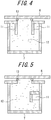
- FIGS. 4 and 5 Illustrated in FIGS. 4 and 5 are a gas body 11, an electrolyte 12, and an O-ring 13. Although the amount of the gas body is not particularly specified, it is preferred to have the gas body to 5 to 15% of the solution in volume fraction in view of the volume expansion resulting from water solidification.
- An inert gas may preferably used for the gas body, because an oxygen-containing gas body affects the anode reaction on the hydrogen detection surface.
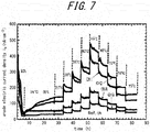
- the measuring apparatus having four cells (CH1 to CH4) configured as illustrated in FIG. 2 was used to conduct an experiment.
- the channel 3 (CH3) served as the base cell, and a stainless foil was attached to be pasted, as the protective film, to a portion serving as the corrosive surface side of CH3.
- FIG. 7 shows changes in anodic current density detected in each channel correspondingly to the changes in temperature shown in FIG. 6 .
- the anodic current density value of the reference electrode (CH3) which was supposed to have no corrosion occurring on the steel sheet surface, also increased along with the increase in temperature.
- the increase of the anodic current density value can be considered ascribable to the fact that the residual electric current resulting from the oxidation current of Pd on the hydrogen detection surface side was increased due to the increase in temperature.
- the temperature dependency of the residual electric current is too large to ignore.
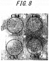
- FIG. 8 is a picture showing the external appearances of the experimented samples on the corrosive surface side.
- the anodic current density value of CH4 was smaller than those of the other CHs because 0.2M NaCl first dropped missed the point, and thus the corroded area on the hydrogen penetration surface side corresponding to the detection surface was smaller.
- the anodic current density value of the reference electrode (CH3) is subtracted from each of the anodic current density values obtained by CH1 and CH2, to thereby obtain accurate current density values of permeated hydrogen in the respective cells (CH1, CH2).
- the current density values of permeated hydrogen thus obtained may be averaged so as to obtain the current density value of hydrogen permeated through the steel sheet as a specimen.
- the amount of permeated hydrogen (amount of penetrated hydrogen) is calculated by the following equations.
- the current density value is converted into the amount of permeated hydrogen based on the following equations.
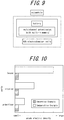
- the measuring apparatus used in Prior Art Example 1 was actually mounted onto an automobile, to thereby construct a measurement system schematically illustrated in FIG. 9 .
- the 4-channel cells were installed at three locations of (a) fender, (b) interior, and (c) underfloor (under surface of the floor).
- a multichannel potentiostat for driving by a battery was prepared, and stored in a trunk together with a dedicated battery.
- a soft steel sheet of 1.0 mm in thickness was similarly used as the sample material as in Example 1.
- the automobile was driven at an average of 40 km/h inside the premise of a steelworks for 6 hours from 9:00 to 15:00 every day of 5 days from Monday to Friday. The automobile was parked in a parking lot from 15:00 to 9:00 on the following day.
- FIG. 10 shows the maximum values of the anodic current density detected during the aforementioned period, in comparison between the example in which the maximum value was compensated based on the reference electrode and the comparative example in which the maximum value was not compensated.
- a commercially-available soft steel sheet (of 0.8 mm in thickness) was used, which was subjected to shearing process so as to sized into 40 ⁇ 50 mm and polished on both surfaces to #2,000. Subsequently, in order to remove the processing layer formed during the polishing, the both surfaces were chemically polished to about 60 ⁇ m in thickness in an aqueous solution of a mixture solution of hydrofluoric acid and hydrogen peroxide solution.
- the hydrogen detection surface was Pd plated to about 100 mm in thickness, using a commercially-available K-pure palladium plating solution (manufactured by Kojima Chemicals Co., Ltd.).
- Sodium hydroxide aqueous solutions of 0.1 N containing dimethylsulfoxide (DMSO) at various ratios were used as the electrolyte aqueous solutions, and the freezing temperature in each case was measured.
- DMSO dimethylsulfoxide
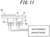
- a measuring apparatus configured by including two cells illustrated in FIG. 11 was employed, in which portions corresponding to 7a and 7b were changed in configuration as follows.
- FIG. 5 The configuration of FIG. 5 was employed with no gas body provided therein, and was filled with an electrolyte solution.
- FIG. 5 The configuration of FIG. 5 was employed, in which nitrogen was filled as the gas body to the amount of 15vol%.
- a steel sheet was installed on the cells configured as described above.
- An Ir/IrO x electrode was disposed as the reference electrode while a Pt wire was disposed as the counter electrode with the potential being set to 0V, and the cells were placed under a corrosive environment.
- An epoxy resin and a stainless foil were arranged on one of the channels of the cells, so as to have one cell exempted from corrosion, in order to compensate changes in temperature.
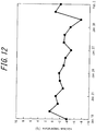
- FIG. 12 shows changes in daily minimum temperature in the period obtained from the website of the Japan Meteorological Agency.
- the driving was performed while being covered with a bag except for a steel sheet surface to be corroded.
- Table 1 shows the date on which a cell fracture or leakage of the electrolyte solution was identified. Table 1 also shows maximum values of the current density obtained for each period, together with compensated maximum values of the current density obtained according to the present invention.
- No. 1 is Comparative Example in which the electrolyte was formed only of a sodium hydroxide aqueous solution. Leakage of the electrolyte resulting from a fracture of the cell was identified on January 27 in Comparative Example of No. 1, whereas no fracture was identified in the cells of No. 2 to No. 4 as Inventive Examples.
- Period 2 and Period 3 the automobile was driven on a wet road, and therefore corrosion of the steel sheet was identified, as well as the increase in current density that has correspondingly occurred. It can be appreciated that the amount of hydrogen generated along with the corrosion and penetrated into the steel sheet was monitored.
- the present invention enables continuous and accurate monitoring of the amount of hydrogen generated due to corrosion of a metallic material and penetrated into the metallic material, and thus the present invention can be suitably applied to a moving body in an ever-changing environment, where each part of the metallic material forming the moving body is exposed to a corrosive environment and corroded, and hydrogen is generated along with the corrosion and penetrates into the metallic material.
Landscapes
- Life Sciences & Earth Sciences (AREA)
- Chemical & Material Sciences (AREA)
- Health & Medical Sciences (AREA)
- General Health & Medical Sciences (AREA)
- Immunology (AREA)
- Physics & Mathematics (AREA)
- Pathology (AREA)
- General Physics & Mathematics (AREA)
- Analytical Chemistry (AREA)
- Biochemistry (AREA)
- Biodiversity & Conservation Biology (AREA)
- Ecology (AREA)
- Environmental Sciences (AREA)
- Environmental & Geological Engineering (AREA)
- Engineering & Computer Science (AREA)
- Molecular Biology (AREA)
- Chemical Kinetics & Catalysis (AREA)
- Electrochemistry (AREA)
- Food Science & Technology (AREA)
- Medicinal Chemistry (AREA)
- Combustion & Propulsion (AREA)
- Testing Resistance To Weather, Investigating Materials By Mechanical Methods (AREA)
Applications Claiming Priority (1)
| Application Number | Priority Date | Filing Date | Title |
|---|---|---|---|
| PCT/JP2012/076256 WO2014054186A1 (ja) | 2012-10-03 | 2012-10-03 | 金属内部への侵入水素量の測定装置 |
Publications (3)
| Publication Number | Publication Date |
|---|---|
| EP2905612A1 EP2905612A1 (en) | 2015-08-12 |
| EP2905612A4 EP2905612A4 (en) | 2015-10-14 |
| EP2905612B1 true EP2905612B1 (en) | 2017-03-01 |
Family
ID=50434543
Family Applications (1)
| Application Number | Title | Priority Date | Filing Date |
|---|---|---|---|
| EP12886067.3A Active EP2905612B1 (en) | 2012-10-03 | 2012-10-03 | Apparatus for measuring amount of hydrogen penetrated into metal |
Country Status (6)
| Country | Link |
|---|---|
| US (1) | US20150219549A1 (cg-RX-API-DMAC7.html) |
| EP (1) | EP2905612B1 (cg-RX-API-DMAC7.html) |
| KR (2) | KR101725747B1 (cg-RX-API-DMAC7.html) |
| CN (2) | CN106908375A (cg-RX-API-DMAC7.html) |
| IN (1) | IN2015DN01668A (cg-RX-API-DMAC7.html) |
| WO (1) | WO2014054186A1 (cg-RX-API-DMAC7.html) |
Families Citing this family (20)
| Publication number | Priority date | Publication date | Assignee | Title |
|---|---|---|---|---|
| JP6693130B2 (ja) * | 2016-01-07 | 2020-05-13 | 日本製鉄株式会社 | 耐水素脆化特性評価方法 |
| US20170324119A1 (en) * | 2016-05-06 | 2017-11-09 | GM Global Technology Operations LLC | Reference electrode implementation with reduced measurement artifacts |
| CN109932337B (zh) * | 2017-12-18 | 2021-08-03 | 有研半导体硅材料股份公司 | 一种用于评价硅基背封膜致密性的装置和方法 |
| WO2019161782A1 (en) | 2018-02-22 | 2019-08-29 | Fg Innovation Ip Company Limited | Methods and devices for measurement reporting in beam operations |
| JP7104326B2 (ja) * | 2018-09-27 | 2022-07-21 | 日本電信電話株式会社 | 腐食性評価装置とその方法 |
| JP7318322B2 (ja) * | 2019-06-07 | 2023-08-01 | 三菱電機株式会社 | 劣化検知装置 |
| JP7149242B2 (ja) * | 2019-09-11 | 2022-10-06 | 株式会社神戸製鋼所 | 水素透過試験装置 |
| CN110687019B (zh) * | 2019-10-30 | 2020-09-08 | 华中科技大学 | 一种用于高温环境下电化学氢渗透测量的装置及方法 |
| US12320739B2 (en) | 2020-02-14 | 2025-06-03 | Jfe Steel Corporation | Method for evaluating delayed fracture of metal material |
| AT521991B1 (de) * | 2020-04-09 | 2022-03-15 | Klueber Lubrication Muenchen Se & Co Kg | Verfahren und vorrichtung zum bestimmen des alterungszustands eines schmierstoffs eines lagers |
| KR102457773B1 (ko) * | 2020-05-22 | 2022-10-21 | 주식회사 케이티앤지 | 에어로졸 생성 장치, 그 동작 방법 및 에어로졸 생성 장치에 사용되는 카트리지 |
| WO2021245848A1 (ja) * | 2020-06-03 | 2021-12-09 | 日本電信電話株式会社 | 水素透過試験装置 |
| CN112051201B (zh) * | 2020-08-26 | 2024-01-26 | 南京工程学院 | 一种循环加载氢渗透实验装置及其使用方法 |
| JP7327353B2 (ja) * | 2020-10-30 | 2023-08-16 | Jfeスチール株式会社 | 鋼中水素分析用サンプルの作製方法、鋼中水素分析方法、鋼板の拡散性水素による脆性劣化の予測方法及び鋼板の検査成績証明方法 |
| JP7380523B2 (ja) * | 2020-10-30 | 2023-11-15 | Jfeスチール株式会社 | 鋼中水素分析用サンプルの作製方法、鋼中水素分析方法、鋼板の拡散性水素による脆性劣化の予測方法及び鋼板の検査成績証明方法 |
| CN114563341B (zh) * | 2021-02-02 | 2025-05-27 | 天津大学 | 一种焊接接头微区氢扩散系数的测定装置及其测定方法和应用 |
| CN113533463A (zh) * | 2021-07-23 | 2021-10-22 | 北京科技大学 | 一种电化学氢渗透传感器及其制备方法 |
| WO2023176027A1 (ja) * | 2022-03-17 | 2023-09-21 | Jfeスチール株式会社 | 表面処理亜鉛めっき鋼板 |
| JP7287590B1 (ja) * | 2022-03-17 | 2023-06-06 | Jfeスチール株式会社 | 表面処理亜鉛めっき鋼板 |
| CN115931538B (zh) * | 2022-12-07 | 2023-08-22 | 中国石油大学(华东) | 一种测量酸性环境中氢对金属应力腐蚀开裂影响程度的方法 |
Family Cites Families (12)
| Publication number | Priority date | Publication date | Assignee | Title |
|---|---|---|---|---|
| US3415685A (en) * | 1964-05-19 | 1968-12-10 | Union Carbide Corp | Gas-depolarizable galvanic cell |
| JPS57119254A (en) * | 1981-01-17 | 1982-07-24 | Nakao Kazutoshi | Galvani battery type o2 sensor with resistance to coldness |
| DE19530203A1 (de) * | 1995-08-17 | 1997-02-20 | Bayer Ag | Verwendung von Polymeren mit wiederkehrenden Succinyleinheiten als Frostschutzmittel |
| JP3904101B2 (ja) * | 1996-09-20 | 2007-04-11 | ソニー株式会社 | 光学装置及び電解液 |
| US6888717B2 (en) * | 2003-06-13 | 2005-05-03 | Kemet Electronics Corporation | Working electrolyte for electrolytic capacitors |
| US7678253B2 (en) * | 2003-08-11 | 2010-03-16 | Mehrooz Zamanzadeh | Atmospheric corrosion sensor |
| JP4028461B2 (ja) | 2003-08-22 | 2007-12-26 | Jfeスチール株式会社 | 遅れ破壊特性の評価方法およびその際行なうめっき方法 |
| CN101071885A (zh) * | 2007-04-18 | 2007-11-14 | 上海奇光生物科技有限公司 | 使用有机-无机复合添加剂的化学电池 |
| JP2010042800A (ja) | 2008-07-16 | 2010-02-25 | Komatsu Ltd | 建設機械のキャブ |
| CN201584439U (zh) * | 2009-06-12 | 2010-09-15 | 千如电机工业股份有限公司 | 二次电池端盖组的结构改良 |
| JP2011179893A (ja) * | 2010-02-26 | 2011-09-15 | Jfe Steel Corp | 金属内部への侵入水素量の測定方法および移動体の金属部位内部へ侵入する水素量のモニタリング方法 |
| CN101832966B (zh) * | 2010-05-28 | 2012-12-19 | 东北大学 | 金属氢渗透性能测定的装置及方法 |
-
2012
- 2012-10-03 IN IN1668DEN2015 patent/IN2015DN01668A/en unknown
- 2012-10-03 CN CN201710060860.8A patent/CN106908375A/zh active Pending
- 2012-10-03 KR KR1020167024815A patent/KR101725747B1/ko active Active
- 2012-10-03 CN CN201280076180.0A patent/CN104685350A/zh active Pending
- 2012-10-03 KR KR1020157005570A patent/KR20150038577A/ko not_active Ceased
- 2012-10-03 EP EP12886067.3A patent/EP2905612B1/en active Active
- 2012-10-03 WO PCT/JP2012/076256 patent/WO2014054186A1/ja not_active Ceased
- 2012-10-03 US US14/429,880 patent/US20150219549A1/en not_active Abandoned
Non-Patent Citations (1)
| Title |
|---|
| None * |
Also Published As
| Publication number | Publication date |
|---|---|
| IN2015DN01668A (cg-RX-API-DMAC7.html) | 2015-07-03 |
| KR20160110554A (ko) | 2016-09-21 |
| KR101725747B1 (ko) | 2017-04-10 |
| US20150219549A1 (en) | 2015-08-06 |
| CN104685350A (zh) | 2015-06-03 |
| KR20150038577A (ko) | 2015-04-08 |
| EP2905612A1 (en) | 2015-08-12 |
| CN106908375A (zh) | 2017-06-30 |
| WO2014054186A1 (ja) | 2014-04-10 |
| EP2905612A4 (en) | 2015-10-14 |
| WO2014054186A8 (ja) | 2015-02-26 |
Similar Documents
| Publication | Publication Date | Title |
|---|---|---|
| EP2905612B1 (en) | Apparatus for measuring amount of hydrogen penetrated into metal | |
| JP5700673B2 (ja) | 金属内部への侵入水素量の測定方法および移動体の金属部位内部へ侵入する水素量のモニタリング方法 | |
| JP2011179893A (ja) | 金属内部への侵入水素量の測定方法および移動体の金属部位内部へ侵入する水素量のモニタリング方法 | |
| Ootsuka et al. | Evaluation of hydrogen absorption into steel in automobile moving environments | |
| JP5777098B2 (ja) | 金属内部への侵入水素量の測定方法および移動体の金属部位内部へ侵入する水素量のモニタリング方法 | |
| EP4012382B1 (en) | Hydrogen permeation test device | |
| Kainuma et al. | Corrosion protection of steel members using an Al-Zn base sacrificial anode and fiber sheet in an atmospheric environment | |
| Omura et al. | Environmental factors affecting hydrogen entry into high strength steel due to atmospheric corrosion | |
| JP5754566B2 (ja) | 金属内部への侵入水素量の測定装置 | |
| JP5888692B2 (ja) | 金属内部への侵入水素量の測定方法および移動体の金属部位内部へ侵入する水素量のモニタリング方法 | |
| Zhang et al. | Corrosion behavior of the joints of carbon fiber reinforced polymers with DP590 steel and Al6022 alloy | |
| JP5979731B2 (ja) | 移動体の金属部位内部へ侵入する水素量のモニタリング方法 | |
| JP6172097B2 (ja) | 自動車車体を構成する鋼材への侵入水素量のモニタリング方法 | |
| JP6130447B2 (ja) | 移動体の金属部位内部へ侵入する水素量のモニタリング方法 | |
| TWI502196B (zh) | Measurement device for intrusion of hydrogen into the metal | |
| US12320739B2 (en) | Method for evaluating delayed fracture of metal material | |
| Hata et al. | Investigation of Relationship between Corrosion and Hydrogen Entry Behavior of Electro-Galvanized Steel under Atmospheric Environment | |
| EP3748333A1 (en) | Physical property evaluation method and device | |
| Aiello | Galvanic sensor for monitoring structural damage | |
| Kitahara et al. | Assessment of hydrogen absorption and delayed fracture limit of high tensile steel sheet in corrosive environment | |
| JP2025088527A (ja) | 侵入水素量測定装置、侵入水素量測定キット、および侵入水素量測定方法 | |
| Klengel et al. | A new method for prediction of corrosion processes in metallization systems for substrates and electrical contacts | |
| Jakab et al. | Corrosion behaviour of copper in sulphuric acid in the presence of N-methylaniline. | |
| Lyon et al. | Electrochemical detection of hydrogen using a solid-state probe | |
| Mansfeld et al. | A Quantitative Electrochemical Test for Porosity in Permalloy Plated Memory Wire |
Legal Events
| Date | Code | Title | Description |
|---|---|---|---|
| PUAI | Public reference made under article 153(3) epc to a published international application that has entered the european phase |
Free format text: ORIGINAL CODE: 0009012 |
|
| 17P | Request for examination filed |
Effective date: 20150303 |
|
| AK | Designated contracting states |
Kind code of ref document: A1 Designated state(s): AL AT BE BG CH CY CZ DE DK EE ES FI FR GB GR HR HU IE IS IT LI LT LU LV MC MK MT NL NO PL PT RO RS SE SI SK SM TR |
|
| AX | Request for extension of the european patent |
Extension state: BA ME |
|
| RA4 | Supplementary search report drawn up and despatched (corrected) |
Effective date: 20150915 |
|
| RIC1 | Information provided on ipc code assigned before grant |
Ipc: G01N 27/26 20060101AFI20150909BHEP Ipc: G01N 17/02 20060101ALI20150909BHEP |
|
| DAX | Request for extension of the european patent (deleted) | ||
| 17Q | First examination report despatched |
Effective date: 20160420 |
|
| REG | Reference to a national code |
Ref country code: DE Ref legal event code: R079 Ref document number: 602012029459 Country of ref document: DE Free format text: PREVIOUS MAIN CLASS: G01N0027260000 Ipc: G01N0017020000 |
|
| GRAP | Despatch of communication of intention to grant a patent |
Free format text: ORIGINAL CODE: EPIDOSNIGR1 |
|
| RIC1 | Information provided on ipc code assigned before grant |
Ipc: G01N 33/20 20060101ALI20160929BHEP Ipc: G01N 17/02 20060101AFI20160929BHEP |
|
| INTG | Intention to grant announced |
Effective date: 20161014 |
|
| GRAS | Grant fee paid |
Free format text: ORIGINAL CODE: EPIDOSNIGR3 |
|
| GRAA | (expected) grant |
Free format text: ORIGINAL CODE: 0009210 |
|
| AK | Designated contracting states |
Kind code of ref document: B1 Designated state(s): AL AT BE BG CH CY CZ DE DK EE ES FI FR GB GR HR HU IE IS IT LI LT LU LV MC MK MT NL NO PL PT RO RS SE SI SK SM TR |
|
| REG | Reference to a national code |
Ref country code: GB Ref legal event code: FG4D |
|
| REG | Reference to a national code |
Ref country code: CH Ref legal event code: EP Ref country code: AT Ref legal event code: REF Ref document number: 871943 Country of ref document: AT Kind code of ref document: T Effective date: 20170315 |
|
| REG | Reference to a national code |
Ref country code: IE Ref legal event code: FG4D |
|
| REG | Reference to a national code |
Ref country code: DE Ref legal event code: R096 Ref document number: 602012029459 Country of ref document: DE |
|
| REG | Reference to a national code |
Ref country code: NL Ref legal event code: MP Effective date: 20170301 |
|
| REG | Reference to a national code |
Ref country code: LT Ref legal event code: MG4D |
|
| REG | Reference to a national code |
Ref country code: AT Ref legal event code: MK05 Ref document number: 871943 Country of ref document: AT Kind code of ref document: T Effective date: 20170301 |
|
| PG25 | Lapsed in a contracting state [announced via postgrant information from national office to epo] |
Ref country code: LT Free format text: LAPSE BECAUSE OF FAILURE TO SUBMIT A TRANSLATION OF THE DESCRIPTION OR TO PAY THE FEE WITHIN THE PRESCRIBED TIME-LIMIT Effective date: 20170301 Ref country code: NO Free format text: LAPSE BECAUSE OF FAILURE TO SUBMIT A TRANSLATION OF THE DESCRIPTION OR TO PAY THE FEE WITHIN THE PRESCRIBED TIME-LIMIT Effective date: 20170601 Ref country code: HR Free format text: LAPSE BECAUSE OF FAILURE TO SUBMIT A TRANSLATION OF THE DESCRIPTION OR TO PAY THE FEE WITHIN THE PRESCRIBED TIME-LIMIT Effective date: 20170301 Ref country code: FI Free format text: LAPSE BECAUSE OF FAILURE TO SUBMIT A TRANSLATION OF THE DESCRIPTION OR TO PAY THE FEE WITHIN THE PRESCRIBED TIME-LIMIT Effective date: 20170301 Ref country code: GR Free format text: LAPSE BECAUSE OF FAILURE TO SUBMIT A TRANSLATION OF THE DESCRIPTION OR TO PAY THE FEE WITHIN THE PRESCRIBED TIME-LIMIT Effective date: 20170602 |
|
| PG25 | Lapsed in a contracting state [announced via postgrant information from national office to epo] |
Ref country code: BG Free format text: LAPSE BECAUSE OF FAILURE TO SUBMIT A TRANSLATION OF THE DESCRIPTION OR TO PAY THE FEE WITHIN THE PRESCRIBED TIME-LIMIT Effective date: 20170601 Ref country code: SE Free format text: LAPSE BECAUSE OF FAILURE TO SUBMIT A TRANSLATION OF THE DESCRIPTION OR TO PAY THE FEE WITHIN THE PRESCRIBED TIME-LIMIT Effective date: 20170301 Ref country code: AT Free format text: LAPSE BECAUSE OF FAILURE TO SUBMIT A TRANSLATION OF THE DESCRIPTION OR TO PAY THE FEE WITHIN THE PRESCRIBED TIME-LIMIT Effective date: 20170301 Ref country code: LV Free format text: LAPSE BECAUSE OF FAILURE TO SUBMIT A TRANSLATION OF THE DESCRIPTION OR TO PAY THE FEE WITHIN THE PRESCRIBED TIME-LIMIT Effective date: 20170301 Ref country code: ES Free format text: LAPSE BECAUSE OF FAILURE TO SUBMIT A TRANSLATION OF THE DESCRIPTION OR TO PAY THE FEE WITHIN THE PRESCRIBED TIME-LIMIT Effective date: 20170301 Ref country code: RS Free format text: LAPSE BECAUSE OF FAILURE TO SUBMIT A TRANSLATION OF THE DESCRIPTION OR TO PAY THE FEE WITHIN THE PRESCRIBED TIME-LIMIT Effective date: 20170301 |
|
| PG25 | Lapsed in a contracting state [announced via postgrant information from national office to epo] |
Ref country code: NL Free format text: LAPSE BECAUSE OF FAILURE TO SUBMIT A TRANSLATION OF THE DESCRIPTION OR TO PAY THE FEE WITHIN THE PRESCRIBED TIME-LIMIT Effective date: 20170301 |
|
| REG | Reference to a national code |
Ref country code: FR Ref legal event code: PLFP Year of fee payment: 6 |
|
| PG25 | Lapsed in a contracting state [announced via postgrant information from national office to epo] |
Ref country code: SK Free format text: LAPSE BECAUSE OF FAILURE TO SUBMIT A TRANSLATION OF THE DESCRIPTION OR TO PAY THE FEE WITHIN THE PRESCRIBED TIME-LIMIT Effective date: 20170301 Ref country code: CZ Free format text: LAPSE BECAUSE OF FAILURE TO SUBMIT A TRANSLATION OF THE DESCRIPTION OR TO PAY THE FEE WITHIN THE PRESCRIBED TIME-LIMIT Effective date: 20170301 Ref country code: EE Free format text: LAPSE BECAUSE OF FAILURE TO SUBMIT A TRANSLATION OF THE DESCRIPTION OR TO PAY THE FEE WITHIN THE PRESCRIBED TIME-LIMIT Effective date: 20170301 Ref country code: IT Free format text: LAPSE BECAUSE OF FAILURE TO SUBMIT A TRANSLATION OF THE DESCRIPTION OR TO PAY THE FEE WITHIN THE PRESCRIBED TIME-LIMIT Effective date: 20170301 Ref country code: RO Free format text: LAPSE BECAUSE OF FAILURE TO SUBMIT A TRANSLATION OF THE DESCRIPTION OR TO PAY THE FEE WITHIN THE PRESCRIBED TIME-LIMIT Effective date: 20170301 |
|
| PG25 | Lapsed in a contracting state [announced via postgrant information from national office to epo] |
Ref country code: PL Free format text: LAPSE BECAUSE OF FAILURE TO SUBMIT A TRANSLATION OF THE DESCRIPTION OR TO PAY THE FEE WITHIN THE PRESCRIBED TIME-LIMIT Effective date: 20170301 Ref country code: SM Free format text: LAPSE BECAUSE OF FAILURE TO SUBMIT A TRANSLATION OF THE DESCRIPTION OR TO PAY THE FEE WITHIN THE PRESCRIBED TIME-LIMIT Effective date: 20170301 Ref country code: PT Free format text: LAPSE BECAUSE OF FAILURE TO SUBMIT A TRANSLATION OF THE DESCRIPTION OR TO PAY THE FEE WITHIN THE PRESCRIBED TIME-LIMIT Effective date: 20170703 Ref country code: IS Free format text: LAPSE BECAUSE OF FAILURE TO SUBMIT A TRANSLATION OF THE DESCRIPTION OR TO PAY THE FEE WITHIN THE PRESCRIBED TIME-LIMIT Effective date: 20170701 |
|
| REG | Reference to a national code |
Ref country code: DE Ref legal event code: R097 Ref document number: 602012029459 Country of ref document: DE |
|
| PLBE | No opposition filed within time limit |
Free format text: ORIGINAL CODE: 0009261 |
|
| STAA | Information on the status of an ep patent application or granted ep patent |
Free format text: STATUS: NO OPPOSITION FILED WITHIN TIME LIMIT |
|
| PG25 | Lapsed in a contracting state [announced via postgrant information from national office to epo] |
Ref country code: DK Free format text: LAPSE BECAUSE OF FAILURE TO SUBMIT A TRANSLATION OF THE DESCRIPTION OR TO PAY THE FEE WITHIN THE PRESCRIBED TIME-LIMIT Effective date: 20170301 |
|
| 26N | No opposition filed |
Effective date: 20171204 |
|
| PG25 | Lapsed in a contracting state [announced via postgrant information from national office to epo] |
Ref country code: SI Free format text: LAPSE BECAUSE OF FAILURE TO SUBMIT A TRANSLATION OF THE DESCRIPTION OR TO PAY THE FEE WITHIN THE PRESCRIBED TIME-LIMIT Effective date: 20170301 |
|
| PG25 | Lapsed in a contracting state [announced via postgrant information from national office to epo] |
Ref country code: MC Free format text: LAPSE BECAUSE OF FAILURE TO SUBMIT A TRANSLATION OF THE DESCRIPTION OR TO PAY THE FEE WITHIN THE PRESCRIBED TIME-LIMIT Effective date: 20170301 |
|
| REG | Reference to a national code |
Ref country code: CH Ref legal event code: PL |
|
| REG | Reference to a national code |
Ref country code: IE Ref legal event code: MM4A |
|
| PG25 | Lapsed in a contracting state [announced via postgrant information from national office to epo] |
Ref country code: LU Free format text: LAPSE BECAUSE OF NON-PAYMENT OF DUE FEES Effective date: 20171003 Ref country code: CH Free format text: LAPSE BECAUSE OF NON-PAYMENT OF DUE FEES Effective date: 20171031 Ref country code: LI Free format text: LAPSE BECAUSE OF NON-PAYMENT OF DUE FEES Effective date: 20171031 |
|
| REG | Reference to a national code |
Ref country code: BE Ref legal event code: MM Effective date: 20171031 |
|
| PG25 | Lapsed in a contracting state [announced via postgrant information from national office to epo] |
Ref country code: BE Free format text: LAPSE BECAUSE OF NON-PAYMENT OF DUE FEES Effective date: 20171031 |
|
| REG | Reference to a national code |
Ref country code: FR Ref legal event code: PLFP Year of fee payment: 7 |
|
| PG25 | Lapsed in a contracting state [announced via postgrant information from national office to epo] |
Ref country code: MT Free format text: LAPSE BECAUSE OF NON-PAYMENT OF DUE FEES Effective date: 20171003 |
|
| PG25 | Lapsed in a contracting state [announced via postgrant information from national office to epo] |
Ref country code: IE Free format text: LAPSE BECAUSE OF NON-PAYMENT OF DUE FEES Effective date: 20171003 |
|
| PG25 | Lapsed in a contracting state [announced via postgrant information from national office to epo] |
Ref country code: HU Free format text: LAPSE BECAUSE OF FAILURE TO SUBMIT A TRANSLATION OF THE DESCRIPTION OR TO PAY THE FEE WITHIN THE PRESCRIBED TIME-LIMIT; INVALID AB INITIO Effective date: 20121003 |
|
| PG25 | Lapsed in a contracting state [announced via postgrant information from national office to epo] |
Ref country code: CY Free format text: LAPSE BECAUSE OF FAILURE TO SUBMIT A TRANSLATION OF THE DESCRIPTION OR TO PAY THE FEE WITHIN THE PRESCRIBED TIME-LIMIT Effective date: 20170301 |
|
| PG25 | Lapsed in a contracting state [announced via postgrant information from national office to epo] |
Ref country code: MK Free format text: LAPSE BECAUSE OF FAILURE TO SUBMIT A TRANSLATION OF THE DESCRIPTION OR TO PAY THE FEE WITHIN THE PRESCRIBED TIME-LIMIT Effective date: 20170301 |
|
| PG25 | Lapsed in a contracting state [announced via postgrant information from national office to epo] |
Ref country code: TR Free format text: LAPSE BECAUSE OF FAILURE TO SUBMIT A TRANSLATION OF THE DESCRIPTION OR TO PAY THE FEE WITHIN THE PRESCRIBED TIME-LIMIT Effective date: 20170301 |
|
| PG25 | Lapsed in a contracting state [announced via postgrant information from national office to epo] |
Ref country code: AL Free format text: LAPSE BECAUSE OF FAILURE TO SUBMIT A TRANSLATION OF THE DESCRIPTION OR TO PAY THE FEE WITHIN THE PRESCRIBED TIME-LIMIT Effective date: 20170301 |
|
| PGFP | Annual fee paid to national office [announced via postgrant information from national office to epo] |
Ref country code: DE Payment date: 20240828 Year of fee payment: 13 |
|
| PGFP | Annual fee paid to national office [announced via postgrant information from national office to epo] |
Ref country code: GB Payment date: 20250828 Year of fee payment: 14 |
|
| PGFP | Annual fee paid to national office [announced via postgrant information from national office to epo] |
Ref country code: FR Payment date: 20250908 Year of fee payment: 14 |