EP2905397B1 - Silo de grue pour le transport de matériaux de construction coulants, comme le béton, les graviers, le sable ou analogues - Google Patents
Silo de grue pour le transport de matériaux de construction coulants, comme le béton, les graviers, le sable ou analogues Download PDFInfo
- Publication number
- EP2905397B1 EP2905397B1 EP14405006.9A EP14405006A EP2905397B1 EP 2905397 B1 EP2905397 B1 EP 2905397B1 EP 14405006 A EP14405006 A EP 14405006A EP 2905397 B1 EP2905397 B1 EP 2905397B1
- Authority
- EP
- European Patent Office
- Prior art keywords
- container
- bucket according
- crane bucket
- crane
- frame part
- Prior art date
- Legal status (The legal status is an assumption and is not a legal conclusion. Google has not performed a legal analysis and makes no representation as to the accuracy of the status listed.)
- Active
Links
Images

Classifications
-
- E—FIXED CONSTRUCTIONS
- E04—BUILDING
- E04G—SCAFFOLDING; FORMS; SHUTTERING; BUILDING IMPLEMENTS OR AIDS, OR THEIR USE; HANDLING BUILDING MATERIALS ON THE SITE; REPAIRING, BREAKING-UP OR OTHER WORK ON EXISTING BUILDINGS
- E04G21/00—Preparing, conveying, or working-up building materials or building elements in situ; Other devices or measures for constructional work
- E04G21/02—Conveying or working-up concrete or similar masses able to be heaped or cast
- E04G21/025—Buckets specially adapted for use with concrete
Definitions
- Kransilo for the transport of pourable building materials such as concrete, gravel, sand or the like.
- the invention relates to a crane silo for the transport of pourable building materials such as concrete, gravel, sand or the like., With a trained for receiving a building material container which is attached to a Ab monoen support frame and at an upper end provided for charging the container filling opening and at an emptying in the direction of discharge funnel-like lower end has an emptying opening for removal of the building material, wherein the emptying opening of the container subsequently an actuatable, provided for determining the removal amount of the building material closure device is arranged, and with one of the closure device from an inoperative position deliverable to an operating position discharge chute in which it is associated with the closure device in an effective manner and arranged in an obliquely downward discharge position.
- the pre-published US 3,146,924 discloses a crane silo according to the preamble of claim 1 and relates to a transportable container for transporting and discharging a quantity of concrete into a formwork.
- the container has an upper cylindrical and a subsequent funnel-shaped lower container part, which are welded together, and a supporting skirt construction.
- the proven functions of known crane silos are to be transferred to a new design, which is characterized by lower weight in favor of higher payloads, simplicity of operability and manufacturing advantages and lower production costs with reliable strength values.
- this object is achieved in that the container in a formed by the tapering to the discharge opening container portion and a uniformly connected to the latter cylindrical, upper container portion transition area by means of the outer circumference of the container subsequently attached, distributed on the circumference of the container, shield-shaped support elements a bottom part of the support frame forming frame part is connected and that the shield-shaped support members are formed for pivotally mounting the chute attached to outlet chute and the frame part for pivoting the outlet chute has a recess.
- This one improvement measure allows excellent and safe operation, a lower design weight than in the known crane silos same capacity, simpler manufacturing methods, improved accessibility to the items for the purpose of cleaning and maintenance.
- the shield-shaped support members are arranged on the container opposite and connected to the latter and the frame part, whereby a stable stability, reduced space and a high rigidity of the connected parts is achieved.
- Container and frame part of the support frame form with the shield-shaped support elements relatively long connecting sections resp. Welding seams that lead to the compact unit of a crane silo.
- the upstanding support elements may be rectangular or trapezoidal in order to further optimize the connection with the upper container portion or the frame part can.
- the standing support element with a recess resp. Opening formed, which also facilitates accessibility to the moving parts.
- the frame part is preferably annular, respectively. adapted to the cross-sectional shape of the upper container portion, so that a tilted position in the suspended state of the crane silo is prevented.
- the frame part may be formed from a tubular profile.
- the proportion of the support elements on the circumference of the upper container portion or at the periphery of the circular frame part may be about 60 °.
- the shield-shaped resp. rectangular or trapezoidal support elements for pivotally mounting the levers attached to the outlet chute are formed and that the frame part has a recess for pivoting or deliverability of the outlet chute to the closure device.
- the recess on the frame part can at least partially compensate for the weight of the laterally suspended or arranged in the operating position discharge chute.
- the emptying opening of the container in the discharge direction can be designed rectangular and ion open as a flap, slide or hose closure VerInstitutvorrichtrung, whereby over the discharge opening bridging of the building materials located in the container is prevented and created optimal Austragsteil are.
- the conveying width of the outlet chute corresponds to at least one outlet width at the closure device.
- a pivot axis of a closure flap is arranged parallel to the longitudinal side of the rectangular emptying opening of the container so that the emptying opening can be optimally utilized.
- a latter connecting common drive shaft is provided which is mounted on the shield-shaped support members, whereby the lever mechanism and the closure device are largely protected behind the support elements.
- the support elements are each formed in the lateral edge distance with a bearing block in which the drive shaft is mounted, so that an optimal arrangement of a firmly connected to the drive shaft operating lever can be made.
- a side edge of the shield-shaped support elements is equipped with an inwardly directed bending edge, on each of which a bearing block is attached.
- the container can be compared with a possible recess of the frame part and / resp. supported between the support elements on the frame part be, for which, for example, a steel pipe is suitable.
- the adjoining the cylindrical upper container portion, tapering in the discharge of the container lower container portion advantageously has by the rectangular discharge opening of the container formed on the periphery, alternately following conical and triangular shell portions that favor dissolution of the container located in the pourable building material.
- the conical shell portions each extend a quarter of the circumference of the lower end of the cylindrical container portion to the individual corners of the rectangular discharge opening, so that a substantially homogeneous funnel shape is formed.
- closure device is attached to the lower end of the container.
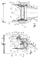
- the Fig. 1 to 4 show a crane silo 1 for receiving and transporting pourable building materials such as concrete, gravel, sand or the like.
- a crane silo 1 for receiving and transporting pourable building materials such as concrete, gravel, sand or the like.
- a building material container 2 which is attached to a removable support frame 3, and attached to the upper edge of the container 2
- Hanger 4 for a hanger (not shown) for transporting the crane silo 1 by means of a tower crane or another lifting device.
- the container 2 has a filling opening 5 and at the lower, funnel-like narrowing end of an emptying opening 6.
- an operable closure device 7 in this case a formed from two flaps 8, 9 flap closure 10, which is attached to the lower end of the container 2.
- the cap closure 10 is in the open position.
- the opening resp. Closing mechanism is described in detail below.
- the attached to the support frame 3 container 2 of the crane silo 1 consists of a cylindrical upper container portion 13 which forms the filling opening 5 and at its upper end the Hanging eyes 4 are attached.
- a lower, tapered container portion 14 connects and forms with the upper container portion 13 a transition region 15 on the container 2.
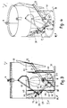
- Distributed on the circumference of the container 2, in the transition region 15 are two shield-shaped support members 16, 17 are attached opposite ends are connected to a frame part 18 of the support frame 3.
- the support elements 16, 17 are butt-welded at the interface between the upper container section 13 and the lower container section 14, or are welded below the interface of the container sections 13, 14 to the lower container section 14 on the outer jacket or on the circumference of the upper container section 13.
- a possible screw or similar connection is not of durability and susceptible to wear, respectively. not recommended, but does not change the design concept.
- the support elements 16, 17 are preferably welded to the frame part 18.
- the frame part 18 When emptying the container 2 via the flap closure 10 without a device for guiding or deflecting the emerging building material, the frame part 18 may be formed as an uninterrupted ring.
- the shield-shaped support members 16, 17, also considered as wall segments or parts or stewhende wall elements, are arranged outside the container 2 opposite and have a width which prevents lateral tilting or buckling despite high load.
- the support elements 16, 17 may be formed as standing rectangles or as trapezoids, which exclude a rotation of the container 2 in the support frame 3.
- Fig. 5 illustrates the support frame 3, formed from frame member 18 for a crane silo 1 with outlet chute 22, including a recess 25 is provided in the frame part 18.
- the open frame part 18 is preferably formed from a steel tube and the ends forming the recess 25 are the frame member 18 opening with bent, formed behind the circumference of the upper container portion 13 projections 31 and close a shearing point with the outlet chute 22.
- the support elements 16, 17 are adapted to the curved shape of the frame part 18 and thereby favors stability.
- the emptying opening 6 on the container 2 is rectangular in the discharge direction and opens into a closure device 7, for which a flap closure 10, a sliding closure or a hose closure can be used.
- the pivot axis 26 -here in the pivot axis of the outlet chute 22 lying parallel to a longitudinal side of the rectangular discharge opening 6 is arranged.
- the conveying width of the outlet chute 22 corresponds to at least one discharge width of the closure device 7 (see Fig. 2 ), wherein the outlet chute 22 tapers conically towards the outlet end and has lateral guide webs 27.
- the present crane silo 1 has, as mentioned above, for actuating the flap closure 10 on both sides of the container 2 arranged lever mechanism 20, 21, respectively, by the operating lever 11, 12 for opening and closing the flap closure 10, respectively.
- the flaps 8, 9 are manually driven.
- the two lever mechanism 20, 21 are connected by a common drive shaft 28 which in each case one attached to the shield-shaped support members 16, 17 resp. provided bearing block 29 is pivotally mounted.
- each one end face 30 of the support elements 16, 17, on which the drive shaft 28 is mounted in the lateral edge distance is suitable.
- connection of the bearing block 29 with the support elements 16, 17 takes place with the arrangement of an inwardly directed bending edge 32 on the affected end face 30 of the support elements 16, 17th
- the lever mechanism 20, 21 each have a fixedly connected to the drive shaft 28 double lever 33, at the ends of the lever with the flaps 8, 9 connected links 34, 35 are hinged.
- Connecting element 36 alternatively / additionally attached to the frame member 18, wherein the preferably formed as a steel tube connecting element 36 is attached to the container 2 approximately in the transition region 15.
- a lever arm 37 is attached to the free end of a tension spring 38 mounted, which is held at the opposite end to the container 2.
- the tension spring 38 pulls lever arm 37, the flap closure 10 in the closed position according to Fig. 3 and during the opening operation by means of operating levers 11, 12, the lever arm 37 is deflected against the force of the tension spring 38.
- the discharge chute 22 is when pivoting in the operating ( Fig. 1 and 2 ) as well as in the non-operational position ( 3 and 4 ) guided over a dead center and held by compression spring 39 each in these positions.
- handles 40 are provided at the outlet chute.
- the conical jacket elements 43 extend from the lower end of the cylindrical container portion 13 to the individual corners of the rectangular discharge opening 6 of the container 2.
- the closure device 7 no matter which of those mentioned, is attached to the lower end of the container 2.
Landscapes
- Engineering & Computer Science (AREA)
- Architecture (AREA)
- Mechanical Engineering (AREA)
- Civil Engineering (AREA)
- Structural Engineering (AREA)
- Filling Or Emptying Of Bunkers, Hoppers, And Tanks (AREA)
Claims (17)
- Silo de grue (1) pour le transport de matériaux de construction coulants, tels que du béton, du gravier, du sable ou similaires, comprenant un récipient (2) réalisé pour recevoir un matériau de construction, qui est fixé à un bâti porteur pouvant être déposé (3) et qui présente à une extrémité supérieure une ouverture de remplissage (5) prévue pour le chargement du récipient (2) et à une extrémité inférieure se rétrécissant en forme d'entonnoir dans la direction d'évacuation, une ouverture d'évacuation (6) pour prélever le matériau de construction, un dispositif de fermeture commandable (7), prévu pour déterminer la quantité de matériau de construction prélevée, étant disposé à la suite de l'ouverture d'évacuation (6) du récipient (2), et une goulotte de déversement (22) pouvant être approchée du dispositif de fermeture (7) d'une position hors fonctionnement dans une position de fonctionnement dans laquelle elle est associée fonctionnellement en termes de transport au dispositif de fermeture (7) et dans laquelle elle est disposée dans une position de décharge orientée obliquement vers le bas, le récipient (2) étant connecté dans une région de transition (15) formée par la portion de récipient (14) se rétrécissant vers l'ouverture d'évacuation (6) et par une portion de récipient supérieure cylindrique (13) connectée de manière uniforme à cette dernière, au moyen d'éléments porteurs (16, 17) en forme d'écran, répartis sur la périphérie du récipient (2) et fixés en se raccordant à la périphérie extérieure du récipient (2), à une partie de cadre (18) formant l'extrémité proche du fond du bâti porteur (16, 17), caractérisé en ce que les éléments porteurs (16, 17) en forme d'écran sont réalisés pour le support pivotant de la goulotte de déversement (22) fixée à des leviers (23, 24) et en ce que la partie de cadre (18) présente un évidement (25) permettant le pivotement de la goulotte de déversement (22).
- Silo de grue selon la revendication 1, caractérisé en ce que les éléments porteurs (16, 17) en forme d'écran sont disposés en regard les uns des autres sur le récipient (2) et sont connectés à celui-ci et à la partie de cadre (18).
- Silo de grue selon la revendication 1 ou 2, caractérisé en ce que les éléments porteurs relevés (16, 17) sont réalisés sous forme rectangulaire ou trapézoïdale.
- Silo de grue selon l'une quelconque des revendications 1 à 3, caractérisé en ce que les éléments porteurs (16, 17) présentent une ouverture ou un évidement (19) réduisant le poids.
- Silo de grue selon l'une quelconque des revendications 1 à 4, caractérisé en ce que la partie de cadre (18) du bâti porteur (3) est réalisée sous forme annulaire.
- Silo de grue selon la revendication 5, caractérisé en ce que la division des éléments porteurs (16, 17) sur la périphérie de la portion de récipient supérieure (13) ou sur la périphérie de la partie de cadre de forme circulaire (18) représente approximativement 60°.
- Silo de grue selon l'une quelconque des revendications 1 à 6, caractérisé en ce que les éléments porteurs (16, 17) et la partie de cadre (18) sont réalisés au moins approximativement suivant la forme périphérique de la portion de récipient supérieure (13).
- Silo de grue selon l'une quelconque des revendications 1 à 7, caractérisé en ce que l'ouverture d'évacuation (6) du récipient (2), considérée dans la direction de décharge, est réalisée sous forme rectangulaire et débouche dans un dispositif de fermeture (7) réalisé sous forme de fermeture à volet (10), à tiroir ou à tuyau flexible.
- Silo de grue selon la revendication 8, caractérisé en ce que la largeur de transport de la goulotte de déversement (22) correspond au moins à la largeur de décharge d'un dispositif de fermeture (7).
- Silo de grue selon la revendication 8 ou 9, comprenant un dispositif de fermeture (7) présentant une fermeture à volet (10), caractérisé en ce qu'un axe de pivotement d'un volet de fermeture (8, 9) est disposé parallèlement au côté longitudinal d'une ouverture d'évacuation (6) rectangulaire du récipient (2).
- Silo de grue selon la revendication 10, comprenant des mécanismes de leviers (20, 21) disposés pour l'actionnement de la fermeture à volet (10) de chaque côté du récipient (2), lesquels sont connectés par un arbre d'entraînement commun (28), caractérisé en ce que l'arbre d'entraînement (28) est supporté sur les éléments porteurs (16, 17 en formé d'écran.
- Silo de grue selon la revendication 11, caractérisé en ce que les éléments porteurs (16, 17) sont réalisés à chaque fois à une distance latérale du bord avec un coussinet (29), dans lesquels coussinets est supporté l'arbre d'entraînement (28).
- Silo de grue selon la revendication 11 ou 12, caractérisé en ce qu'une arête latérale des éléments porteurs en forme d'écran (16, 17) est réalisée avec une arête de flexion (32) orientée vers l'intérieur, sur laquelle est à chaque fois fixé un coussinet (29).
- Silo de grue selon l'une quelconque des revendications 1 à 13, caractérisé en ce que le récipient (2) est supporté en regard de l'évidement (25) de la partie de cadre (18) et entre les éléments porteurs (16, 17) sur la partie de cadre (18), respectivement est connecté à cette dernière.
- Silo de grue selon l'une quelconque des revendications 1 à 14, caractérisé en ce que la portion de récipient inférieure (14) se raccordant à la portion de récipient cylindrique (13), se rétrécissant dans la direction d'évacuation, présente des parties d'enveloppe se suivant en alternance, de forme conique (43) et triangulaire (42), formées sur la périphérie par l'ouverture d'évacuation rectangulaire (6) du récipient (2).
- Silo de grue selon la revendication 15, caractérisé en ce que les parties d'enveloppe de forme conique (43) s'étendent depuis l'extrémité inférieure de la portion de récipient cylindrique (13) jusqu'aux coins de l'ouverture d'évacuation rectangulaire (6).
- Silo de grue selon l'une quelconque des revendications 1 à 16, caractérisé en ce que le dispositif de fermeture (7) est fixé au niveau de l'extrémité de récipient inférieure.
Priority Applications (1)
| Application Number | Priority Date | Filing Date | Title |
|---|---|---|---|
| EP14405006.9A EP2905397B1 (fr) | 2014-02-07 | 2014-02-07 | Silo de grue pour le transport de matériaux de construction coulants, comme le béton, les graviers, le sable ou analogues |
Applications Claiming Priority (1)
| Application Number | Priority Date | Filing Date | Title |
|---|---|---|---|
| EP14405006.9A EP2905397B1 (fr) | 2014-02-07 | 2014-02-07 | Silo de grue pour le transport de matériaux de construction coulants, comme le béton, les graviers, le sable ou analogues |
Publications (2)
| Publication Number | Publication Date |
|---|---|
| EP2905397A1 EP2905397A1 (fr) | 2015-08-12 |
| EP2905397B1 true EP2905397B1 (fr) | 2016-09-21 |
Family
ID=50193424
Family Applications (1)
| Application Number | Title | Priority Date | Filing Date |
|---|---|---|---|
| EP14405006.9A Active EP2905397B1 (fr) | 2014-02-07 | 2014-02-07 | Silo de grue pour le transport de matériaux de construction coulants, comme le béton, les graviers, le sable ou analogues |
Country Status (1)
| Country | Link |
|---|---|
| EP (1) | EP2905397B1 (fr) |
Family Cites Families (8)
| Publication number | Priority date | Publication date | Assignee | Title |
|---|---|---|---|---|
| US2134643A (en) * | 1936-06-27 | 1938-10-25 | Insley Mfg Corp | Concrete conveying bucket |
| GB718411A (en) * | 1949-02-26 | 1954-11-17 | Johnson Co C S | Improved skip bucket |
| US3146924A (en) * | 1963-05-13 | 1964-09-01 | Miller Swivel Products Inc | Concrete dump bucket |
| US4798510A (en) * | 1988-01-14 | 1989-01-17 | Lazenby James E | Concrete bucket assembly rigidly mounted for vertical tilting and rotational movement to a forklift vehicle |
| CH685831A5 (de) | 1994-01-17 | 1995-10-13 | Eduard Voegtli | Einrichtung zum Transport von schüttfähigen Baumaterialien bzw. Baustoffen. |
| US6435581B1 (en) * | 2001-02-13 | 2002-08-20 | James L. House | Three-yard concrete bucket with integral ladder |
| EP1491703B1 (fr) | 2003-06-22 | 2013-08-21 | Obrist Baugeräte AG | Godet de grue pour le transport de matériaux de construction |
| EP2465655B1 (fr) | 2010-12-18 | 2015-02-18 | Obrist Baugeräte AG | Procédé de vidage d'un silo de grue développé pour la réception et le transport suspendu de matériaux de construction coulants |
-
2014
- 2014-02-07 EP EP14405006.9A patent/EP2905397B1/fr active Active
Also Published As
| Publication number | Publication date |
|---|---|
| EP2905397A1 (fr) | 2015-08-12 |
Similar Documents
| Publication | Publication Date | Title |
|---|---|---|
| EP3436644A1 (fr) | Récipient de collecte de matière d'une drague suceuse | |
| EP2535482B1 (fr) | Silo de grue pour le transport de matériaux de construction coulants, comme le béton, les graviers, le sable ou analogues | |
| DE4204330A1 (de) | Fahrmischerpumpe | |
| EP2905397B1 (fr) | Silo de grue pour le transport de matériaux de construction coulants, comme le béton, les graviers, le sable ou analogues | |
| DE3708653C2 (de) | Verladevorrichtung für lose Verladung von staubigen Schüttgütern | |
| DE102011113422A1 (de) | Grabkopf für einen kontinuierlichen Schiffsentlader | |
| DE2430786A1 (de) | Drehvorrichtung fuer den transport von stahlgiesspfannen | |
| EP0185745A1 (fr) | Silo de section circulaire pour matieres granuleuses | |
| DE102009021167B4 (de) | Mobile Brechanlage | |
| EP1491703B1 (fr) | Godet de grue pour le transport de matériaux de construction | |
| CH685831A5 (de) | Einrichtung zum Transport von schüttfähigen Baumaterialien bzw. Baustoffen. | |
| EP1830017B1 (fr) | Benne pour le transport de matériaux de construction en vrac, comme béton, gravillons, sable | |
| EP0830926A2 (fr) | Conteneur pour béton | |
| EP1382381A1 (fr) | Mélangeur horizontal ayant un diametre supérieur à sa longueur | |
| EP2980334B1 (fr) | Silo de grue pour le transport et le traitement de matériaux de construction coulants | |
| DE4440335B4 (de) | Beschickungsvorrichtung für Schüttgut | |
| DE3205564C2 (de) | Silo für Trockengips und andere Trockenmörtel | |
| DE2524857C3 (de) | Transport- und Sammelfahrzeuug für Schüttgut | |
| EP0418581B1 (fr) | Dispositif de chargement par aspiration pour matières en vrac et liquides | |
| DE19819307C2 (de) | Anordnung zum Verteilen von Schüttgut, insbesondere Beton, auf verschiedene Verbraucherstellen | |
| DE202009012067U1 (de) | Vorrichtung zur Ausgabe von Schüttgut, insbesondere Beton | |
| DE102005049560B4 (de) | Skip | |
| DE2807046C3 (de) | Anlage zum Beschicken von Speicherbehältern mit Schüttgut | |
| DE102004040812A1 (de) | Pfannenkippeinrichtung | |
| EP0571355A1 (fr) | Réservoir |
Legal Events
| Date | Code | Title | Description |
|---|---|---|---|
| PUAI | Public reference made under article 153(3) epc to a published international application that has entered the european phase |
Free format text: ORIGINAL CODE: 0009012 |
|
| AK | Designated contracting states |
Kind code of ref document: A1 Designated state(s): AL AT BE BG CH CY CZ DE DK EE ES FI FR GB GR HR HU IE IS IT LI LT LU LV MC MK MT NL NO PL PT RO RS SE SI SK SM TR |
|
| AX | Request for extension of the european patent |
Extension state: BA ME |
|
| 17P | Request for examination filed |
Effective date: 20160206 |
|
| RBV | Designated contracting states (corrected) |
Designated state(s): AL AT BE BG CH CY CZ DE DK EE ES FI FR GB GR HR HU IE IS IT LI LT LU LV MC MK MT NL NO PL PT RO RS SE SI SK SM TR |
|
| GRAP | Despatch of communication of intention to grant a patent |
Free format text: ORIGINAL CODE: EPIDOSNIGR1 |
|
| INTG | Intention to grant announced |
Effective date: 20160506 |
|
| GRAS | Grant fee paid |
Free format text: ORIGINAL CODE: EPIDOSNIGR3 |
|
| GRAA | (expected) grant |
Free format text: ORIGINAL CODE: 0009210 |
|
| AK | Designated contracting states |
Kind code of ref document: B1 Designated state(s): AL AT BE BG CH CY CZ DE DK EE ES FI FR GB GR HR HU IE IS IT LI LT LU LV MC MK MT NL NO PL PT RO RS SE SI SK SM TR |
|
| REG | Reference to a national code |
Ref country code: GB Ref legal event code: FG4D Free format text: NOT ENGLISH |
|
| REG | Reference to a national code |
Ref country code: CH Ref legal event code: EP |
|
| REG | Reference to a national code |
Ref country code: CH Ref legal event code: NV Representative=s name: WERNER FENNER PATENTANWALT, CH |
|
| REG | Reference to a national code |
Ref country code: AT Ref legal event code: REF Ref document number: 831199 Country of ref document: AT Kind code of ref document: T Effective date: 20161015 |
|
| REG | Reference to a national code |
Ref country code: IE Ref legal event code: FG4D Free format text: LANGUAGE OF EP DOCUMENT: GERMAN |
|
| REG | Reference to a national code |
Ref country code: DE Ref legal event code: R096 Ref document number: 502014001525 Country of ref document: DE |
|
| REG | Reference to a national code |
Ref country code: LT Ref legal event code: MG4D Ref country code: NL Ref legal event code: MP Effective date: 20160921 |
|
| PG25 | Lapsed in a contracting state [announced via postgrant information from national office to epo] |
Ref country code: FI Free format text: LAPSE BECAUSE OF FAILURE TO SUBMIT A TRANSLATION OF THE DESCRIPTION OR TO PAY THE FEE WITHIN THE PRESCRIBED TIME-LIMIT Effective date: 20160921 Ref country code: LT Free format text: LAPSE BECAUSE OF FAILURE TO SUBMIT A TRANSLATION OF THE DESCRIPTION OR TO PAY THE FEE WITHIN THE PRESCRIBED TIME-LIMIT Effective date: 20160921 Ref country code: RS Free format text: LAPSE BECAUSE OF FAILURE TO SUBMIT A TRANSLATION OF THE DESCRIPTION OR TO PAY THE FEE WITHIN THE PRESCRIBED TIME-LIMIT Effective date: 20160921 Ref country code: NO Free format text: LAPSE BECAUSE OF FAILURE TO SUBMIT A TRANSLATION OF THE DESCRIPTION OR TO PAY THE FEE WITHIN THE PRESCRIBED TIME-LIMIT Effective date: 20161221 |
|
| REG | Reference to a national code |
Ref country code: FR Ref legal event code: PLFP Year of fee payment: 4 |
|
| PG25 | Lapsed in a contracting state [announced via postgrant information from national office to epo] |
Ref country code: GR Free format text: LAPSE BECAUSE OF FAILURE TO SUBMIT A TRANSLATION OF THE DESCRIPTION OR TO PAY THE FEE WITHIN THE PRESCRIBED TIME-LIMIT Effective date: 20161222 Ref country code: SE Free format text: LAPSE BECAUSE OF FAILURE TO SUBMIT A TRANSLATION OF THE DESCRIPTION OR TO PAY THE FEE WITHIN THE PRESCRIBED TIME-LIMIT Effective date: 20160921 Ref country code: NL Free format text: LAPSE BECAUSE OF FAILURE TO SUBMIT A TRANSLATION OF THE DESCRIPTION OR TO PAY THE FEE WITHIN THE PRESCRIBED TIME-LIMIT Effective date: 20160921 Ref country code: LV Free format text: LAPSE BECAUSE OF FAILURE TO SUBMIT A TRANSLATION OF THE DESCRIPTION OR TO PAY THE FEE WITHIN THE PRESCRIBED TIME-LIMIT Effective date: 20160921 |
|
| PG25 | Lapsed in a contracting state [announced via postgrant information from national office to epo] |
Ref country code: EE Free format text: LAPSE BECAUSE OF FAILURE TO SUBMIT A TRANSLATION OF THE DESCRIPTION OR TO PAY THE FEE WITHIN THE PRESCRIBED TIME-LIMIT Effective date: 20160921 Ref country code: RO Free format text: LAPSE BECAUSE OF FAILURE TO SUBMIT A TRANSLATION OF THE DESCRIPTION OR TO PAY THE FEE WITHIN THE PRESCRIBED TIME-LIMIT Effective date: 20160921 |
|
| PG25 | Lapsed in a contracting state [announced via postgrant information from national office to epo] |
Ref country code: BE Free format text: LAPSE BECAUSE OF NON-PAYMENT OF DUE FEES Effective date: 20170228 Ref country code: BG Free format text: LAPSE BECAUSE OF FAILURE TO SUBMIT A TRANSLATION OF THE DESCRIPTION OR TO PAY THE FEE WITHIN THE PRESCRIBED TIME-LIMIT Effective date: 20161221 Ref country code: PL Free format text: LAPSE BECAUSE OF FAILURE TO SUBMIT A TRANSLATION OF THE DESCRIPTION OR TO PAY THE FEE WITHIN THE PRESCRIBED TIME-LIMIT Effective date: 20160921 Ref country code: CZ Free format text: LAPSE BECAUSE OF FAILURE TO SUBMIT A TRANSLATION OF THE DESCRIPTION OR TO PAY THE FEE WITHIN THE PRESCRIBED TIME-LIMIT Effective date: 20160921 Ref country code: PT Free format text: LAPSE BECAUSE OF FAILURE TO SUBMIT A TRANSLATION OF THE DESCRIPTION OR TO PAY THE FEE WITHIN THE PRESCRIBED TIME-LIMIT Effective date: 20170123 Ref country code: SK Free format text: LAPSE BECAUSE OF FAILURE TO SUBMIT A TRANSLATION OF THE DESCRIPTION OR TO PAY THE FEE WITHIN THE PRESCRIBED TIME-LIMIT Effective date: 20160921 Ref country code: SM Free format text: LAPSE BECAUSE OF FAILURE TO SUBMIT A TRANSLATION OF THE DESCRIPTION OR TO PAY THE FEE WITHIN THE PRESCRIBED TIME-LIMIT Effective date: 20160921 Ref country code: IS Free format text: LAPSE BECAUSE OF FAILURE TO SUBMIT A TRANSLATION OF THE DESCRIPTION OR TO PAY THE FEE WITHIN THE PRESCRIBED TIME-LIMIT Effective date: 20170121 Ref country code: ES Free format text: LAPSE BECAUSE OF FAILURE TO SUBMIT A TRANSLATION OF THE DESCRIPTION OR TO PAY THE FEE WITHIN THE PRESCRIBED TIME-LIMIT Effective date: 20160921 |
|
| REG | Reference to a national code |
Ref country code: DE Ref legal event code: R097 Ref document number: 502014001525 Country of ref document: DE |
|
| PLBE | No opposition filed within time limit |
Free format text: ORIGINAL CODE: 0009261 |
|
| STAA | Information on the status of an ep patent application or granted ep patent |
Free format text: STATUS: NO OPPOSITION FILED WITHIN TIME LIMIT |
|
| PG25 | Lapsed in a contracting state [announced via postgrant information from national office to epo] |
Ref country code: DK Free format text: LAPSE BECAUSE OF FAILURE TO SUBMIT A TRANSLATION OF THE DESCRIPTION OR TO PAY THE FEE WITHIN THE PRESCRIBED TIME-LIMIT Effective date: 20160921 |
|
| 26N | No opposition filed |
Effective date: 20170622 |
|
| PG25 | Lapsed in a contracting state [announced via postgrant information from national office to epo] |
Ref country code: MC Free format text: LAPSE BECAUSE OF FAILURE TO SUBMIT A TRANSLATION OF THE DESCRIPTION OR TO PAY THE FEE WITHIN THE PRESCRIBED TIME-LIMIT Effective date: 20160921 |
|
| PG25 | Lapsed in a contracting state [announced via postgrant information from national office to epo] |
Ref country code: SI Free format text: LAPSE BECAUSE OF FAILURE TO SUBMIT A TRANSLATION OF THE DESCRIPTION OR TO PAY THE FEE WITHIN THE PRESCRIBED TIME-LIMIT Effective date: 20160921 |
|
| PG25 | Lapsed in a contracting state [announced via postgrant information from national office to epo] |
Ref country code: LU Free format text: LAPSE BECAUSE OF NON-PAYMENT OF DUE FEES Effective date: 20170207 |
|
| REG | Reference to a national code |
Ref country code: BE Ref legal event code: MM Effective date: 20170228 |
|
| REG | Reference to a national code |
Ref country code: FR Ref legal event code: PLFP Year of fee payment: 5 |
|
| PG25 | Lapsed in a contracting state [announced via postgrant information from national office to epo] |
Ref country code: MT Free format text: LAPSE BECAUSE OF FAILURE TO SUBMIT A TRANSLATION OF THE DESCRIPTION OR TO PAY THE FEE WITHIN THE PRESCRIBED TIME-LIMIT Effective date: 20160921 |
|
| GBPC | Gb: european patent ceased through non-payment of renewal fee |
Effective date: 20180207 |
|
| PG25 | Lapsed in a contracting state [announced via postgrant information from national office to epo] |
Ref country code: AL Free format text: LAPSE BECAUSE OF FAILURE TO SUBMIT A TRANSLATION OF THE DESCRIPTION OR TO PAY THE FEE WITHIN THE PRESCRIBED TIME-LIMIT Effective date: 20160921 |
|
| PG25 | Lapsed in a contracting state [announced via postgrant information from national office to epo] |
Ref country code: GB Free format text: LAPSE BECAUSE OF NON-PAYMENT OF DUE FEES Effective date: 20180207 |
|
| REG | Reference to a national code |
Ref country code: IE Ref legal event code: MM4A |
|
| PG25 | Lapsed in a contracting state [announced via postgrant information from national office to epo] |
Ref country code: IE Free format text: LAPSE BECAUSE OF NON-PAYMENT OF DUE FEES Effective date: 20170207 |
|
| PG25 | Lapsed in a contracting state [announced via postgrant information from national office to epo] |
Ref country code: HU Free format text: LAPSE BECAUSE OF FAILURE TO SUBMIT A TRANSLATION OF THE DESCRIPTION OR TO PAY THE FEE WITHIN THE PRESCRIBED TIME-LIMIT; INVALID AB INITIO Effective date: 20140207 |
|
| PG25 | Lapsed in a contracting state [announced via postgrant information from national office to epo] |
Ref country code: CY Free format text: LAPSE BECAUSE OF FAILURE TO SUBMIT A TRANSLATION OF THE DESCRIPTION OR TO PAY THE FEE WITHIN THE PRESCRIBED TIME-LIMIT Effective date: 20160921 |
|
| PG25 | Lapsed in a contracting state [announced via postgrant information from national office to epo] |
Ref country code: MK Free format text: LAPSE BECAUSE OF FAILURE TO SUBMIT A TRANSLATION OF THE DESCRIPTION OR TO PAY THE FEE WITHIN THE PRESCRIBED TIME-LIMIT Effective date: 20160921 |
|
| PG25 | Lapsed in a contracting state [announced via postgrant information from national office to epo] |
Ref country code: TR Free format text: LAPSE BECAUSE OF FAILURE TO SUBMIT A TRANSLATION OF THE DESCRIPTION OR TO PAY THE FEE WITHIN THE PRESCRIBED TIME-LIMIT Effective date: 20160921 |
|
| PG25 | Lapsed in a contracting state [announced via postgrant information from national office to epo] |
Ref country code: HR Free format text: LAPSE BECAUSE OF FAILURE TO SUBMIT A TRANSLATION OF THE DESCRIPTION OR TO PAY THE FEE WITHIN THE PRESCRIBED TIME-LIMIT Effective date: 20160921 |
|
| REG | Reference to a national code |
Ref country code: DE Ref legal event code: R082 Ref document number: 502014001525 Country of ref document: DE Representative=s name: LEINWEBER & ZIMMERMANN PATENTANWALTS-PARTG MBB, DE Ref country code: DE Ref legal event code: R081 Ref document number: 502014001525 Country of ref document: DE Owner name: CONSTREQ AG, CH Free format text: FORMER OWNER: OBRIST BAUGERAETE AG, WALLBACH, CH |
|
| REG | Reference to a national code |
Ref country code: CH Ref legal event code: NV Representative=s name: SERAINA FENNER, CH |
|
| REG | Reference to a national code |
Ref country code: CH Ref legal event code: PFA Owner name: CONSTREQ AG, CH Free format text: FORMER OWNER: OBRIST BAUGERAETE AG, CH |
|
| REG | Reference to a national code |
Ref country code: AT Ref legal event code: HC Ref document number: 831199 Country of ref document: AT Kind code of ref document: T Owner name: CONSTREQ AG, CH Effective date: 20210217 |
|
| P01 | Opt-out of the competence of the unified patent court (upc) registered |
Effective date: 20230514 |
|
| PGFP | Annual fee paid to national office [announced via postgrant information from national office to epo] |
Ref country code: DE Payment date: 20250213 Year of fee payment: 12 |
|
| PGFP | Annual fee paid to national office [announced via postgrant information from national office to epo] |
Ref country code: AT Payment date: 20250225 Year of fee payment: 12 |
|
| PGFP | Annual fee paid to national office [announced via postgrant information from national office to epo] |
Ref country code: FR Payment date: 20250218 Year of fee payment: 12 |
|
| PGFP | Annual fee paid to national office [announced via postgrant information from national office to epo] |
Ref country code: IT Payment date: 20250226 Year of fee payment: 12 |
|
| PGFP | Annual fee paid to national office [announced via postgrant information from national office to epo] |
Ref country code: CH Payment date: 20250515 Year of fee payment: 12 |