EP2904689B1 - Transformerless on-site generation - Google Patents
Transformerless on-site generation Download PDFInfo
- Publication number
- EP2904689B1 EP2904689B1 EP13843748.8A EP13843748A EP2904689B1 EP 2904689 B1 EP2904689 B1 EP 2904689B1 EP 13843748 A EP13843748 A EP 13843748A EP 2904689 B1 EP2904689 B1 EP 2904689B1
- Authority
- EP
- European Patent Office
- Prior art keywords
- voltage
- electrolytic cells
- plate
- line voltage
- cell
- Prior art date
- Legal status (The legal status is an assumption and is not a legal conclusion. Google has not performed a legal analysis and makes no representation as to the accuracy of the status listed.)
- Active
Links
Images


Classifications
-
- C—CHEMISTRY; METALLURGY
- C25—ELECTROLYTIC OR ELECTROPHORETIC PROCESSES; APPARATUS THEREFOR
- C25B—ELECTROLYTIC OR ELECTROPHORETIC PROCESSES FOR THE PRODUCTION OF COMPOUNDS OR NON-METALS; APPARATUS THEREFOR
- C25B15/00—Operating or servicing cells
- C25B15/02—Process control or regulation
-
- C—CHEMISTRY; METALLURGY
- C25—ELECTROLYTIC OR ELECTROPHORETIC PROCESSES; APPARATUS THEREFOR
- C25B—ELECTROLYTIC OR ELECTROPHORETIC PROCESSES FOR THE PRODUCTION OF COMPOUNDS OR NON-METALS; APPARATUS THEREFOR
- C25B11/00—Electrodes; Manufacture thereof not otherwise provided for
- C25B11/02—Electrodes; Manufacture thereof not otherwise provided for characterised by shape or form
- C25B11/036—Bipolar electrodes
-
- C—CHEMISTRY; METALLURGY
- C25—ELECTROLYTIC OR ELECTROPHORETIC PROCESSES; APPARATUS THEREFOR
- C25B—ELECTROLYTIC OR ELECTROPHORETIC PROCESSES FOR THE PRODUCTION OF COMPOUNDS OR NON-METALS; APPARATUS THEREFOR
- C25B15/00—Operating or servicing cells
-
- C—CHEMISTRY; METALLURGY
- C25—ELECTROLYTIC OR ELECTROPHORETIC PROCESSES; APPARATUS THEREFOR
- C25B—ELECTROLYTIC OR ELECTROPHORETIC PROCESSES FOR THE PRODUCTION OF COMPOUNDS OR NON-METALS; APPARATUS THEREFOR
- C25B15/00—Operating or servicing cells
- C25B15/02—Process control or regulation
- C25B15/023—Measuring, analysing or testing during electrolytic production
- C25B15/025—Measuring, analysing or testing during electrolytic production of electrolyte parameters
- C25B15/033—Conductivity
-
- C—CHEMISTRY; METALLURGY
- C25—ELECTROLYTIC OR ELECTROPHORETIC PROCESSES; APPARATUS THEREFOR
- C25B—ELECTROLYTIC OR ELECTROPHORETIC PROCESSES FOR THE PRODUCTION OF COMPOUNDS OR NON-METALS; APPARATUS THEREFOR
- C25B9/00—Cells or assemblies of cells; Constructional parts of cells; Assemblies of constructional parts, e.g. electrode-diaphragm assemblies; Process-related cell features
- C25B9/60—Constructional parts of cells
- C25B9/65—Means for supplying current; Electrode connections; Electric inter-cell connections
-
- C—CHEMISTRY; METALLURGY
- C25—ELECTROLYTIC OR ELECTROPHORETIC PROCESSES; APPARATUS THEREFOR
- C25B—ELECTROLYTIC OR ELECTROPHORETIC PROCESSES FOR THE PRODUCTION OF COMPOUNDS OR NON-METALS; APPARATUS THEREFOR
- C25B9/00—Cells or assemblies of cells; Constructional parts of cells; Assemblies of constructional parts, e.g. electrode-diaphragm assemblies; Process-related cell features
- C25B9/70—Assemblies comprising two or more cells
- C25B9/73—Assemblies comprising two or more cells of the filter-press type
- C25B9/75—Assemblies comprising two or more cells of the filter-press type having bipolar electrodes
-
- H—ELECTRICITY
- H02—GENERATION; CONVERSION OR DISTRIBUTION OF ELECTRIC POWER
- H02M—APPARATUS FOR CONVERSION BETWEEN AC AND AC, BETWEEN AC AND DC, OR BETWEEN DC AND DC, AND FOR USE WITH MAINS OR SIMILAR POWER SUPPLY SYSTEMS; CONVERSION OF DC OR AC INPUT POWER INTO SURGE OUTPUT POWER; CONTROL OR REGULATION THEREOF
- H02M3/00—Conversion of DC power input into DC power output
- H02M3/02—Conversion of DC power input into DC power output without intermediate conversion into AC
- H02M3/04—Conversion of DC power input into DC power output without intermediate conversion into AC by static converters
- H02M3/10—Conversion of DC power input into DC power output without intermediate conversion into AC by static converters using discharge tubes with control electrode or semiconductor devices with control electrode
- H02M3/145—Conversion of DC power input into DC power output without intermediate conversion into AC by static converters using discharge tubes with control electrode or semiconductor devices with control electrode using devices of a triode or transistor type requiring continuous application of a control signal
- H02M3/155—Conversion of DC power input into DC power output without intermediate conversion into AC by static converters using discharge tubes with control electrode or semiconductor devices with control electrode using devices of a triode or transistor type requiring continuous application of a control signal using semiconductor devices only
-
- H—ELECTRICITY
- H02—GENERATION; CONVERSION OR DISTRIBUTION OF ELECTRIC POWER
- H02M—APPARATUS FOR CONVERSION BETWEEN AC AND AC, BETWEEN AC AND DC, OR BETWEEN DC AND DC, AND FOR USE WITH MAINS OR SIMILAR POWER SUPPLY SYSTEMS; CONVERSION OF DC OR AC INPUT POWER INTO SURGE OUTPUT POWER; CONTROL OR REGULATION THEREOF
- H02M7/00—Conversion of AC power input into DC power output; Conversion of DC power input into AC power output
- H02M7/02—Conversion of AC power input into DC power output without possibility of reversal
- H02M7/04—Conversion of AC power input into DC power output without possibility of reversal by static converters
- H02M7/12—Conversion of AC power input into DC power output without possibility of reversal by static converters using discharge tubes with control electrode or semiconductor devices with control electrode
- H02M7/21—Conversion of AC power input into DC power output without possibility of reversal by static converters using discharge tubes with control electrode or semiconductor devices with control electrode using devices of a triode or transistor type requiring continuous application of a control signal
- H02M7/217—Conversion of AC power input into DC power output without possibility of reversal by static converters using discharge tubes with control electrode or semiconductor devices with control electrode using devices of a triode or transistor type requiring continuous application of a control signal using semiconductor devices only
-
- H—ELECTRICITY
- H02—GENERATION; CONVERSION OR DISTRIBUTION OF ELECTRIC POWER
- H02M—APPARATUS FOR CONVERSION BETWEEN AC AND AC, BETWEEN AC AND DC, OR BETWEEN DC AND DC, AND FOR USE WITH MAINS OR SIMILAR POWER SUPPLY SYSTEMS; CONVERSION OF DC OR AC INPUT POWER INTO SURGE OUTPUT POWER; CONTROL OR REGULATION THEREOF
- H02M1/00—Details of apparatus for conversion
- H02M1/0067—Converter structures employing plural converter units, other than for parallel operation of the units on a single load
- H02M1/007—Plural converter units in cascade
Definitions
- the present invention is apparatus and configuration for providing power to one or more electrolytic cells without requiring a large transformer to take incoming AC voltage to a lower DC voltage. This innovation is a substantial cost and footprint improvement over other electrolytic cell designs.
- Electrolytic cells of either mono-polar or bi-polar configuration for on-site generation (OSG) of oxidants are typically arranged in electrically parallel configurations. Voltages used for a mono-polar cell typically vary from 3.5 - 6.0 Volts plate to plate. Bipolar electrolytic cells often have somewhat higher voltages, but they are typically run at DC voltages of 9.0 - 42.0 Volts.
- a switching DC power supply, or transformer coupled with other devices is typically used to take the available incoming AC voltage(s) (for example 1 10V, 220V, 400V, 480V, 600V) to provide a constant, lower DC voltage at the cell. This methodology/apparatus of stepping down the voltage has substantial disadvantages.
- the cost of goods sold (COGS) associated with the step down voltage apparatus are typically a substantial part of the overall cost of the on-site generator (often 10-50%). Stepping down voltage also results in substantial power losses, increasing the operating cost of generating oxidants or other chemicals on-site and creating more heat, which must somehow be dealt with by cooling fans, etc. Lastly, the footprint and weight associated with the apparatus used to step down the voltage is a substantial part of the overall footprint and weight (typically 10-45%).
- US 4085028 A describes an apparatus for electrolyzing a dilute aqueous brine solution for the electrochemical preparation of hypochlorites or chlorine from dilute water solutions of chlorides comprising a full-wave bridge rectifier adapted to be electrically connected directly to a source of alternating current and an electrode assembly connected across said rectifier comprising a negative electrode, a positive electrode, and one or more bipolar electrodes.
- An embodiment of the present invention is an apparatus as defined in claim 1.
- the apparatus comprises one or more electrolytic cells comprising a number of intermediate electrodes sufficient to enable the apparatus to operate within only a percentage of a rectified line voltage while maintaining a desired plate to plate voltage between adjacent intermediate electrodes, the apparatus not comprising a transformer.
- the apparatus comprises voltage regulation provided by a buck converter circuit or a boost converter circuit. The voltage regulation can vary a voltage across the one or more electrolytic cells up to approximately twenty percent of the rectified line voltage. If more than one electrolytic cells are used, they are preferably connected in series.
- the apparatus further comprises a plurality of contactors in an H-bridge configuration for reversing the polarity of the one or more electrolytic cells in order to enable self-cleaning of the one or more electrolytic cells.
- Another embodiment of the present invention is a method for performing electrolysis as defined in claim 4, the method comprising rectifying incoming line voltage; providing one or more electrolytic cells comprising a number of intermediate electrodes sufficient to enable the one or more electrolytic cells to operate within only a percentage of a rectified line voltage while maintaining a desired plate to plate voltage between adjacent intermediate electrodes; and varying the rectified line voltage without using a transformer.
- Varying the rectified line voltage is performed using a buck converter circuit or a boost converter circuit.
- Varying the rectified line voltage preferably comprises varying a voltage across the one or more electrolytic cells up to approximately twenty percent of the rectified line voltage.
- Varying the rectified line voltage optionally accommodates fluctuations in the incoming line voltage or changes the chemical products, for example the quantity of hydrogen and hypochlorite to hydrogen peroxide ratio, produced by the one or more electrolytic cells.
- Varying the rectified line voltage optionally comprises accommodating a varying conductivity of electrolyte, such as that produced by fluctuations in salinity and/or temperature of seawater. If a plurality of cells is used, the method preferably comprises connecting them in series. The method further comprises reversing the polarity of the one or more electrolytic cells using a plurality of contactors in an H-bridge configuration, thereby self-cleaning the one or more electrolytic cells.
- Varying the rectified line voltage using a boost converter circuit preferably comprises harvesting energy from a low voltage power source or matching a solar array output to a desired voltage across the one or more electrolytic cells.
- Embodiments of the invention are methods and apparatuses to provide power to one or more electrolytic cells.
- the apparatuses take an incoming power of one type and convert it to power suitable to drive a bank or line of electrolytic cells arranged electrically in series and/or a single large bi-polar electrolytic cell designed to handle the high voltages.
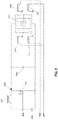
- incoming AC power 10 is passed through fuse 30 and, via contactor control 20, diode rectifier 40 and is then applied to a bipolar cell or a plurality of electrolytic cells 50, the latter preferably arranged in series, which typically cannot use conventional AC power directly.
- the diode rectifier turns the alternating current (AC) into a wavy direct current (DC).
- the effective DC voltage on the cell or cell line is approximately 1.4 ⁇ VAC.
- N electrolytic cells designed to operate at 1/N ⁇ (1 .4 ⁇ VAC), each with plate to plate voltages between intermediate electrodes from 3.5-7V, are preferably arranged electrically in series allowing for elimination of the transformer.
- FIG. 2 is a similar embodiment (not according to the present invention), in which incoming AC power 60 is passed through fuse 80, diode rectifier 90 via contactor control 70, and filter capacitor 95, which smoothes out the wavy DC voltage, which is then applied to a bipolar cell or a plurality of electrolytic cells 100.
- FIG. 3 is a schematic of another embodiment (not according to the present invention) that comprises contactors (i.e. switches and/or relays) arranged in an H-bridge configuration to reverse the polarity to clean the electrolytic cells (preferably for a short time and/or at lower currents).
- Incoming AC power 110 is passed through fuse 130 diode rectifier 140 via contactor control 120, and filter capacitor 145, and is then applied to a bipolar cell or a plurality of electrolytic cells 150.
- Relays 151, 152, 153, 154 are preferably arranged in an H-bridge configuration and are controlled by forward polarity signal 156 and reverse polarity signal 158.
- the circuit in FIG. 4 of an embodiment according to the invention uses a buck converter in addition to the configuration of FIG. 3 .
- Incoming AC power 160 is passed through fuse 180 diode rectifier 190 via contactor control 170, and filter capacitor 195, and is then applied to a bipolar cell or a plurality of electrolytic cells 200.
- Relays 201, 202, 203, 204 are arranged in an H-bridge configuration and are controlled by forward polarity signal 206 and reverse polarity signal 208.
- the buck converter by means of altering the Pulse Width Modulation (PWM) signal 210 of MOSFET switch 220 provides an efficient way to step the voltage down from the rectified mains.
- Buck converter also preferably comprises diode 230, filter capacitor 240, and inductor 250.
- a voltage can be selected that is appropriate for the electro- chemistry required by the user. That is, by using different electrode to electrode voltages, different chemistries can be achieved. For example, hydrogen production can be increased or decreased, or hypochlorite production can be favored over hydrogen peroxide (or vice versa).
- the present invention can more easily compensate for the different mains voltages found throughout the world.
- Manufacturing industrial equipment for the international market requires the equipment to utilize different AC mains voltages.
- Three phase power throughout the world can be any of 208, 220, 230, 240, 346, 380, 400, 415, 480, 600, or 690 VAC at 50-60 Hz.
- This requires special transformers designed for a specific range of voltages or step up/down transformers used in conjunction with a standard transformer designed for operation of the cell line at a specific set voltage.
- a typical example is that of a transformer primary designed to utilize 480 VAC mains and a rectified secondary that produces 42 VDC.
- a step up transformer of at least the same power rating and approximately the size would be required to be installed at the site in addition to the standard system. This can substantially increase the overall cost and footprint of the installed system. There is also a decrease in overall power efficiency due to coupling losses of two transformers.
- the power supply must adjust to the conductivity of the sea water dynamically, since the conductivity of seawater varies by salinity and temperature and is not constant.
- the buck configuration can use current feedback instead of voltage and thus become a constant current source instead. This is difficult or impossible to implement using transformers.
- the electrolytic cell or cells are designed to accommodate close to the rectified line voltage without any voltage regulation.
- the cell or cells are configured with the number of intermediate electrodes that enable the system to operate with voltage regulation of exactly, or alternatively only a percentage of, the rectified line voltage to operate at the desired plate to plate voltage in each cell.
- a boost converter is used to step up a lower voltage from battery 310 to a voltage suitable to drive a cell (preferably bipolar) or cell line 320.
- the boost converter preferably is operated via PWM signal 300 and comprises inductor 330, diode 340, and Mosfet 350.
- Optional filter capacitor 360 smoothes out the voltage.
- Relays 370, 375, 380, 385 are preferably arranged in an H-bridge configuration and are controlled by forward polarity signal 390 and reverse polarity signal 395.
- This configuration provides a way to harvest energy from, for example, just a few solar cells or small human powered generators that can be used to power small portable water treatment equipment.
- This configuration can also be used to optimize larger off the grid applications that utilize photovoltaic energy generation by better matching the output of solar array to the required cell line.
- Table 1 a five pound system is scaled up in three different configurations to produce 675 pounds of chlorine a day with a 480 volt three phase input (VAC).
- VAC three phase input
- the plate to plate voltage for each configuration was 5 volts.
- the first two configurations use conventional methods.
Landscapes
- Chemical & Material Sciences (AREA)
- Engineering & Computer Science (AREA)
- Metallurgy (AREA)
- Organic Chemistry (AREA)
- Chemical Kinetics & Catalysis (AREA)
- Electrochemistry (AREA)
- Materials Engineering (AREA)
- Power Engineering (AREA)
- Automation & Control Theory (AREA)
- Analytical Chemistry (AREA)
- Electrolytic Production Of Non-Metals, Compounds, Apparatuses Therefor (AREA)
- Water Treatment By Electricity Or Magnetism (AREA)
- Rectifiers (AREA)
- Dc-Dc Converters (AREA)
Applications Claiming Priority (2)
| Application Number | Priority Date | Filing Date | Title |
|---|---|---|---|
| US201261710468P | 2012-10-05 | 2012-10-05 | |
| PCT/US2013/063743 WO2014055992A1 (en) | 2012-10-05 | 2013-10-07 | Transformerless on-site generation |
Publications (3)
| Publication Number | Publication Date |
|---|---|
| EP2904689A1 EP2904689A1 (en) | 2015-08-12 |
| EP2904689A4 EP2904689A4 (en) | 2016-02-10 |
| EP2904689B1 true EP2904689B1 (en) | 2022-11-30 |
Family
ID=50431876
Family Applications (1)
| Application Number | Title | Priority Date | Filing Date |
|---|---|---|---|
| EP13843748.8A Active EP2904689B1 (en) | 2012-10-05 | 2013-10-07 | Transformerless on-site generation |
Country Status (9)
| Country | Link |
|---|---|
| US (1) | US20140097093A1 (enExample) |
| EP (1) | EP2904689B1 (enExample) |
| JP (1) | JP2015537116A (enExample) |
| KR (2) | KR20150067760A (enExample) |
| CA (1) | CA2926075C (enExample) |
| ES (1) | ES2934683T3 (enExample) |
| PT (1) | PT2904689T (enExample) |
| SG (1) | SG11201502269WA (enExample) |
| WO (1) | WO2014055992A1 (enExample) |
Families Citing this family (11)
| Publication number | Priority date | Publication date | Assignee | Title |
|---|---|---|---|---|
| JP6230451B2 (ja) * | 2014-03-11 | 2017-11-15 | 株式会社東芝 | 光化学反応装置および化学反応装置 |
| ES3032920T3 (en) * | 2017-03-06 | 2025-07-28 | Evoqua Water Tech Llc | Implementation of feedback control for improved electrochemical system design |
| EP3556905A1 (de) * | 2018-04-19 | 2019-10-23 | Siemens Aktiengesellschaft | Schaltungsanordnung, verfahren zum betrieb einer schaltungsanordnung und elektrolyseeinrichtung |
| US11699972B2 (en) * | 2018-08-24 | 2023-07-11 | Johnson Controls Tyco IP Holdings LLP | Variable speed motor drive with integrated motor heating systems and methods |
| FR3105266B1 (fr) * | 2019-12-19 | 2021-11-19 | Air Liquide | Combinaison de systèmes d’électronique de puissance régulés en filtration harmonique et/ou en compensation de puissance réactive alimentant une unité asservie de production d’hydrogène et d’oxygène par électrolyse de l’eau |
| US11352703B2 (en) * | 2020-06-10 | 2022-06-07 | The Florida International University Board Of Trustees | Bipolar exfoliation and in-situ deposition of high-quality reduced graphene |
| DE102021114207B4 (de) * | 2021-06-01 | 2023-04-27 | Convertertec Deutschland Gmbh | Schaltungsanordnung und Verfahren zur Bereitstellung elektrischer Leistung für große DC-Lasten |
| WO2023107607A1 (en) * | 2021-12-08 | 2023-06-15 | Electric Hydrogen Co | Variable inverter based power control |
| CN117254675A (zh) * | 2022-06-10 | 2023-12-19 | 佛山市顺德区美的电子科技有限公司 | 电解发生装置及其控制方法、电器设备 |
| JPWO2024075239A1 (enExample) * | 2022-10-06 | 2024-04-11 | ||
| WO2024111043A1 (ja) * | 2022-11-22 | 2024-05-30 | 株式会社Tmeic | 電解槽用電源装置 |
Citations (5)
| Publication number | Priority date | Publication date | Assignee | Title |
|---|---|---|---|---|
| US4085028A (en) * | 1974-11-21 | 1978-04-18 | Electro-Chlor Corporation | Electrolytic chlorination device |
| US4100052A (en) * | 1976-11-11 | 1978-07-11 | Diamond Shamrock Corporation | Electrolytic generation of halogen biocides |
| US4248690A (en) * | 1980-01-28 | 1981-02-03 | Pennwalt Corporation | Apparatus for production of sodium hypochlorite |
| US6217741B1 (en) * | 1998-10-13 | 2001-04-17 | Morinaga Engineering Co., Ltd. | Method for manufacturing bactericide |
| JP2011249161A (ja) * | 2010-05-27 | 2011-12-08 | Aquafairy Kk | 発電装置 |
Family Cites Families (38)
| Publication number | Priority date | Publication date | Assignee | Title |
|---|---|---|---|---|
| US3616355A (en) * | 1968-08-05 | 1971-10-26 | Kdi Chloro Guard Corp | Method of generating enhanced biocidal activity in the electroylsis of chlorine containing solutions and the resulting solutions |
| CA914610A (en) * | 1970-06-26 | 1972-11-14 | Chemetics International Ltd. | Multi-monopolar electrolytic cell assembly and system |
| US3942104A (en) * | 1974-05-03 | 1976-03-02 | Engelhard Minerals & Chemicals Corporation | Cell balance detector for electrolytic cell assemblies |
| JPS5914555B2 (ja) * | 1975-03-31 | 1984-04-05 | 旭化成株式会社 | 電解槽への給電給液方法 |
| US4235694A (en) * | 1978-10-06 | 1980-11-25 | Hall Frederick F | Electrolytic cells for hydrogen gas production |
| US4316787A (en) * | 1979-08-06 | 1982-02-23 | Themy Constantinos D | High voltage electrolytic cell |
| US4236992A (en) * | 1979-08-06 | 1980-12-02 | Themy Constantinos D | High voltage electrolytic cell |
| JPS586789B2 (ja) * | 1980-01-22 | 1983-02-07 | 旭硝子株式会社 | 酸化パラジウム系陽極の劣化防止方法 |
| US4372827A (en) * | 1980-11-10 | 1983-02-08 | Panclor S.A. | Novel horizontal diaphragmless electrolyzer |
| US4395675A (en) * | 1981-10-22 | 1983-07-26 | Bell Telephone Laboratories, Incorporated | Transformerless noninverting buck boost switching regulator |
| JPS58110685A (ja) * | 1981-12-25 | 1983-07-01 | インスチツ−ト・エレクトロスワルキ・イメ−ニ・イ−・オ−・パト−ナ・アカデミ−・ナウク・ウクラインスコイ・エスエスエル | 水素と酸素の混合物製造用フイルタプレス型電解槽 |
| US4424105A (en) * | 1982-08-05 | 1984-01-03 | Henes Products Corp. | Gas generator with regulated current source |
| AU619050B2 (en) * | 1988-10-11 | 1992-01-16 | Sal-Chlor Pty. Ltd. | Improvements in pool chlorinators |
| JPH03150383A (ja) * | 1989-11-08 | 1991-06-26 | Japan Carlit Co Ltd:The | フィルタープレス型複極電解槽 |
| US5130006A (en) * | 1989-11-09 | 1992-07-14 | Oligny Louis Andre | Pyramidal shaped electrolysis cell |
| JPH0413881A (ja) * | 1990-05-02 | 1992-01-17 | Japan Carlit Co Ltd:The | フィルタープレス型複極式電解槽 |
| US5254226A (en) * | 1992-05-05 | 1993-10-19 | Ad Rem Manufacturing, Inc. | Electrolytic cell assembly and process for production of bromine |
| JPH07242402A (ja) * | 1994-03-02 | 1995-09-19 | Sasakura Eng Co Ltd | 水電解式オゾン発生装置 |
| US5795459A (en) * | 1996-07-29 | 1998-08-18 | Sweeney; Charles T. | Apparatus and method for water purification |
| US6198257B1 (en) * | 1999-10-01 | 2001-03-06 | Metropolitan Industries, Inc. | Transformerless DC-to-AC power converter and method |
| JP3414720B2 (ja) * | 2001-02-02 | 2003-06-09 | 神鋼パンテツク株式会社 | 水電解装置 |
| TW547489U (en) * | 2001-09-14 | 2003-08-11 | Shihlin Electric & Engineering | Hydrogen oxygen generation device with insertion type electrolytic tank |
| US6740436B2 (en) * | 2002-08-22 | 2004-05-25 | Natural Energy Resources | Hydrogen/oxygen generating system with temperature control |
| US7625470B2 (en) * | 2004-04-13 | 2009-12-01 | Whirlpool Corporation | Electrolytic chemical generator for automatic cleaning device |
| JP2005350716A (ja) * | 2004-06-10 | 2005-12-22 | Wakamiya Kogyo Kk | 水槽の電解殺菌装置 |
| US20060114642A1 (en) * | 2004-11-30 | 2006-06-01 | Yan Liu | Systems and methods for integrated VAR compensation and hydrogen production |
| US7996171B2 (en) * | 2005-01-27 | 2011-08-09 | Electro Industries/Gauge Tech | Intelligent electronic device with broad-range high accuracy |
| EP1929615B1 (en) * | 2005-08-16 | 2018-11-14 | MKS Instruments, Inc. | Load resonant type power supply for ozonizer |
| TW200709544A (en) * | 2005-08-29 | 2007-03-01 | Ind Tech Res Inst | Transformer-free power conversion circuit for parallel connection with commercial electricity system |
| US8007654B2 (en) * | 2006-02-10 | 2011-08-30 | Tennant Company | Electrochemically activated anolyte and catholyte liquid |
| US8025787B2 (en) * | 2006-02-10 | 2011-09-27 | Tennant Company | Method and apparatus for generating, applying and neutralizing an electrochemically activated liquid |
| JP4872393B2 (ja) * | 2006-03-14 | 2012-02-08 | 株式会社日立製作所 | 風力発電水素製造装置 |
| CN101495811A (zh) * | 2006-05-01 | 2009-07-29 | 克罗普利控股有限公司 | 使用由电解槽生产的可燃气体烹饪的方法和设备 |
| US20100252445A1 (en) * | 2007-07-07 | 2010-10-07 | Donald James Highgate | Electrolysis of Salt Water |
| US20090205972A1 (en) * | 2008-01-04 | 2009-08-20 | Miox Corporation | Electrolytic Purifier |
| WO2009155044A2 (en) * | 2008-05-28 | 2009-12-23 | Miox Corporation | Reverse polarity cleaning and electronic flow control systems for low intervention electrolytic chemical generators |
| JP2012512333A (ja) * | 2008-12-17 | 2012-05-31 | テナント カンパニー | 消毒特性を強化するために液体を通じて電荷を印加する方法および装置 |
| US8058752B2 (en) * | 2009-02-13 | 2011-11-15 | Miasole | Thin-film photovoltaic power element with integrated low-profile high-efficiency DC-DC converter |
-
2013
- 2013-10-07 PT PT138437488T patent/PT2904689T/pt unknown
- 2013-10-07 WO PCT/US2013/063743 patent/WO2014055992A1/en not_active Ceased
- 2013-10-07 EP EP13843748.8A patent/EP2904689B1/en active Active
- 2013-10-07 CA CA2926075A patent/CA2926075C/en active Active
- 2013-10-07 SG SG11201502269WA patent/SG11201502269WA/en unknown
- 2013-10-07 ES ES13843748T patent/ES2934683T3/es active Active
- 2013-10-07 KR KR1020157011760A patent/KR20150067760A/ko not_active Ceased
- 2013-10-07 KR KR1020217038882A patent/KR20210147116A/ko not_active Ceased
- 2013-10-07 JP JP2015535877A patent/JP2015537116A/ja active Pending
- 2013-10-07 US US14/047,934 patent/US20140097093A1/en not_active Abandoned
Patent Citations (5)
| Publication number | Priority date | Publication date | Assignee | Title |
|---|---|---|---|---|
| US4085028A (en) * | 1974-11-21 | 1978-04-18 | Electro-Chlor Corporation | Electrolytic chlorination device |
| US4100052A (en) * | 1976-11-11 | 1978-07-11 | Diamond Shamrock Corporation | Electrolytic generation of halogen biocides |
| US4248690A (en) * | 1980-01-28 | 1981-02-03 | Pennwalt Corporation | Apparatus for production of sodium hypochlorite |
| US6217741B1 (en) * | 1998-10-13 | 2001-04-17 | Morinaga Engineering Co., Ltd. | Method for manufacturing bactericide |
| JP2011249161A (ja) * | 2010-05-27 | 2011-12-08 | Aquafairy Kk | 発電装置 |
Also Published As
| Publication number | Publication date |
|---|---|
| JP2015537116A (ja) | 2015-12-24 |
| ES2934683T3 (es) | 2023-02-24 |
| WO2014055992A1 (en) | 2014-04-10 |
| KR20150067760A (ko) | 2015-06-18 |
| KR20210147116A (ko) | 2021-12-06 |
| SG11201502269WA (en) | 2015-04-29 |
| US20140097093A1 (en) | 2014-04-10 |
| CA2926075C (en) | 2023-02-14 |
| CA2926075A1 (en) | 2014-04-10 |
| PT2904689T (pt) | 2023-01-03 |
| EP2904689A1 (en) | 2015-08-12 |
| EP2904689A4 (en) | 2016-02-10 |
Similar Documents
| Publication | Publication Date | Title |
|---|---|---|
| EP2904689B1 (en) | Transformerless on-site generation | |
| DK2956572T3 (en) | Electrolysis roof and electrolyzer | |
| CN103368437A (zh) | 逆变器组件和包括该逆变器组件的太阳能发电站 | |
| RU2013114728A (ru) | Электрическое устройство энергообеспечения для приводных устройств рельсовых транспортных средств | |
| US20240410063A1 (en) | An electrolyzer system and a method for water electrolysis | |
| JP2022551402A (ja) | 電気化学的プロセスのためのシステム及び方法 | |
| JP2015164028A (ja) | 太陽光発電を利用した電解システム | |
| EP4465512A1 (en) | High-power rectification arrangement for an electrolyser system | |
| CN107374547A (zh) | 除菌装置和家用电器 | |
| CN112187060A (zh) | 隔离低压直流切换电路、换路装置及控制方法 | |
| CN111668872A (zh) | 一种适用于交直流混合配电网的光伏并网装置 | |
| CN205453270U (zh) | 一种带有光伏组件的混合供电水泵系统 | |
| RU2015126781A (ru) | Уменьшение проблем, связанных с качеством электроэнергии, посредством гибридной сети | |
| CN113337835A (zh) | 一种利用新能源发电的离网电解槽电源控制方法和装置 | |
| CN205283409U (zh) | 一种升压系统 | |
| CN205081698U (zh) | 一种整流电源 | |
| CN106400097A (zh) | 一种加热电极除垢方法 | |
| CN211151816U (zh) | 一种应用于臭氧水产生装置中的启动电路及臭氧水喷壶 | |
| CN111620415A (zh) | 一种基于新能源的电化学除藻方法 | |
| CN119932578A (zh) | 一种电解水制氢系统 | |
| EP4569605A2 (en) | A system and a method for an electrochemical process | |
| CN113328509A (zh) | 降压模块及纯水电解制氢系统 | |
| TW200411090A (en) | Electrolytic device and control method | |
| Neba et al. | Utility Interactive Operations of PWM Current Source Inverter-Induction Motor System with Photovoltaic Generation | |
| Park et al. | 50kw Photovoltaic Generation System of Chosun university Dormitory for Model House Power Supply |
Legal Events
| Date | Code | Title | Description |
|---|---|---|---|
| PUAI | Public reference made under article 153(3) epc to a published international application that has entered the european phase |
Free format text: ORIGINAL CODE: 0009012 |
|
| 17P | Request for examination filed |
Effective date: 20150506 |
|
| AK | Designated contracting states |
Kind code of ref document: A1 Designated state(s): AL AT BE BG CH CY CZ DE DK EE ES FI FR GB GR HR HU IE IS IT LI LT LU LV MC MK MT NL NO PL PT RO RS SE SI SK SM TR |
|
| AX | Request for extension of the european patent |
Extension state: BA ME |
|
| DAX | Request for extension of the european patent (deleted) | ||
| RA4 | Supplementary search report drawn up and despatched (corrected) |
Effective date: 20160111 |
|
| RIC1 | Information provided on ipc code assigned before grant |
Ipc: H02M 7/217 20060101ALI20160104BHEP Ipc: C25B 15/02 20060101ALI20160104BHEP Ipc: H02J 7/02 20060101AFI20160104BHEP Ipc: C25B 9/06 20060101ALI20160104BHEP Ipc: C25B 9/04 20060101ALI20160104BHEP Ipc: H02M 3/155 20060101ALI20160104BHEP Ipc: C25B 9/18 20060101ALI20160104BHEP |
|
| RAP1 | Party data changed (applicant data changed or rights of an application transferred) |
Owner name: JOHNSON MATTHEY PUBLIC LIMITED COMPANY |
|
| STAA | Information on the status of an ep patent application or granted ep patent |
Free format text: STATUS: EXAMINATION IS IN PROGRESS |
|
| 17Q | First examination report despatched |
Effective date: 20180323 |
|
| RAP1 | Party data changed (applicant data changed or rights of an application transferred) |
Owner name: DE NORA HOLDINGS US, INC. |
|
| REG | Reference to a national code |
Ref country code: DE Ref legal event code: R079 Ref document number: 602013082972 Country of ref document: DE Free format text: PREVIOUS MAIN CLASS: H02J0007020000 Ipc: C25B0015033000 |
|
| GRAP | Despatch of communication of intention to grant a patent |
Free format text: ORIGINAL CODE: EPIDOSNIGR1 |
|
| STAA | Information on the status of an ep patent application or granted ep patent |
Free format text: STATUS: GRANT OF PATENT IS INTENDED |
|
| RIC1 | Information provided on ipc code assigned before grant |
Ipc: C25B 15/00 20060101ALI20220505BHEP Ipc: H02M 7/217 20060101ALI20220505BHEP Ipc: H02M 3/155 20060101ALI20220505BHEP Ipc: C25B 11/036 20210101ALI20220505BHEP Ipc: C25B 9/65 20210101ALI20220505BHEP Ipc: C25B 9/75 20210101ALI20220505BHEP Ipc: C25B 15/033 20210101AFI20220505BHEP |
|
| INTG | Intention to grant announced |
Effective date: 20220531 |
|
| GRAS | Grant fee paid |
Free format text: ORIGINAL CODE: EPIDOSNIGR3 |
|
| GRAA | (expected) grant |
Free format text: ORIGINAL CODE: 0009210 |
|
| STAA | Information on the status of an ep patent application or granted ep patent |
Free format text: STATUS: THE PATENT HAS BEEN GRANTED |
|
| AK | Designated contracting states |
Kind code of ref document: B1 Designated state(s): AL AT BE BG CH CY CZ DE DK EE ES FI FR GB GR HR HU IE IS IT LI LT LU LV MC MK MT NL NO PL PT RO RS SE SI SK SM TR |
|
| REG | Reference to a national code |
Ref country code: CH Ref legal event code: EP Ref country code: GB Ref legal event code: FG4D |
|
| REG | Reference to a national code |
Ref country code: AT Ref legal event code: REF Ref document number: 1534737 Country of ref document: AT Kind code of ref document: T Effective date: 20221215 |
|
| REG | Reference to a national code |
Ref country code: IE Ref legal event code: FG4D |
|
| REG | Reference to a national code |
Ref country code: DE Ref legal event code: R096 Ref document number: 602013082972 Country of ref document: DE |
|
| REG | Reference to a national code |
Ref country code: DK Ref legal event code: T3 Effective date: 20221219 |
|
| REG | Reference to a national code |
Ref country code: PT Ref legal event code: SC4A Ref document number: 2904689 Country of ref document: PT Date of ref document: 20230103 Kind code of ref document: T Free format text: AVAILABILITY OF NATIONAL TRANSLATION Effective date: 20221227 |
|
| REG | Reference to a national code |
Ref country code: NL Ref legal event code: FP |
|
| REG | Reference to a national code |
Ref country code: NO Ref legal event code: T2 Effective date: 20221130 |
|
| REG | Reference to a national code |
Ref country code: RO Ref legal event code: EPE |
|
| REG | Reference to a national code |
Ref country code: ES Ref legal event code: FG2A Ref document number: 2934683 Country of ref document: ES Kind code of ref document: T3 Effective date: 20230224 |
|
| REG | Reference to a national code |
Ref country code: SE Ref legal event code: TRGR |
|
| REG | Reference to a national code |
Ref country code: GR Ref legal event code: EP Ref document number: 20230400197 Country of ref document: GR Effective date: 20230307 |
|
| REG | Reference to a national code |
Ref country code: LT Ref legal event code: MG9D |
|
| PG25 | Lapsed in a contracting state [announced via postgrant information from national office to epo] |
Ref country code: LT Free format text: LAPSE BECAUSE OF FAILURE TO SUBMIT A TRANSLATION OF THE DESCRIPTION OR TO PAY THE FEE WITHIN THE PRESCRIBED TIME-LIMIT Effective date: 20221130 Ref country code: FI Free format text: LAPSE BECAUSE OF FAILURE TO SUBMIT A TRANSLATION OF THE DESCRIPTION OR TO PAY THE FEE WITHIN THE PRESCRIBED TIME-LIMIT Effective date: 20221130 |
|
| PG25 | Lapsed in a contracting state [announced via postgrant information from national office to epo] |
Ref country code: RS Free format text: LAPSE BECAUSE OF FAILURE TO SUBMIT A TRANSLATION OF THE DESCRIPTION OR TO PAY THE FEE WITHIN THE PRESCRIBED TIME-LIMIT Effective date: 20221130 Ref country code: PL Free format text: LAPSE BECAUSE OF FAILURE TO SUBMIT A TRANSLATION OF THE DESCRIPTION OR TO PAY THE FEE WITHIN THE PRESCRIBED TIME-LIMIT Effective date: 20221130 Ref country code: LV Free format text: LAPSE BECAUSE OF FAILURE TO SUBMIT A TRANSLATION OF THE DESCRIPTION OR TO PAY THE FEE WITHIN THE PRESCRIBED TIME-LIMIT Effective date: 20221130 Ref country code: IS Free format text: LAPSE BECAUSE OF FAILURE TO SUBMIT A TRANSLATION OF THE DESCRIPTION OR TO PAY THE FEE WITHIN THE PRESCRIBED TIME-LIMIT Effective date: 20230330 Ref country code: HR Free format text: LAPSE BECAUSE OF FAILURE TO SUBMIT A TRANSLATION OF THE DESCRIPTION OR TO PAY THE FEE WITHIN THE PRESCRIBED TIME-LIMIT Effective date: 20221130 |
|
| P01 | Opt-out of the competence of the unified patent court (upc) registered |
Effective date: 20230526 |
|
| PG25 | Lapsed in a contracting state [announced via postgrant information from national office to epo] |
Ref country code: SM Free format text: LAPSE BECAUSE OF FAILURE TO SUBMIT A TRANSLATION OF THE DESCRIPTION OR TO PAY THE FEE WITHIN THE PRESCRIBED TIME-LIMIT Effective date: 20221130 Ref country code: EE Free format text: LAPSE BECAUSE OF FAILURE TO SUBMIT A TRANSLATION OF THE DESCRIPTION OR TO PAY THE FEE WITHIN THE PRESCRIBED TIME-LIMIT Effective date: 20221130 |
|
| PG25 | Lapsed in a contracting state [announced via postgrant information from national office to epo] |
Ref country code: SK Free format text: LAPSE BECAUSE OF FAILURE TO SUBMIT A TRANSLATION OF THE DESCRIPTION OR TO PAY THE FEE WITHIN THE PRESCRIBED TIME-LIMIT Effective date: 20221130 Ref country code: AL Free format text: LAPSE BECAUSE OF FAILURE TO SUBMIT A TRANSLATION OF THE DESCRIPTION OR TO PAY THE FEE WITHIN THE PRESCRIBED TIME-LIMIT Effective date: 20221130 |
|
| REG | Reference to a national code |
Ref country code: DE Ref legal event code: R097 Ref document number: 602013082972 Country of ref document: DE |
|
| PLBE | No opposition filed within time limit |
Free format text: ORIGINAL CODE: 0009261 |
|
| STAA | Information on the status of an ep patent application or granted ep patent |
Free format text: STATUS: NO OPPOSITION FILED WITHIN TIME LIMIT |
|
| 26N | No opposition filed |
Effective date: 20230831 |
|
| PG25 | Lapsed in a contracting state [announced via postgrant information from national office to epo] |
Ref country code: SI Free format text: LAPSE BECAUSE OF FAILURE TO SUBMIT A TRANSLATION OF THE DESCRIPTION OR TO PAY THE FEE WITHIN THE PRESCRIBED TIME-LIMIT Effective date: 20221130 |
|
| PG25 | Lapsed in a contracting state [announced via postgrant information from national office to epo] |
Ref country code: MC Free format text: LAPSE BECAUSE OF FAILURE TO SUBMIT A TRANSLATION OF THE DESCRIPTION OR TO PAY THE FEE WITHIN THE PRESCRIBED TIME-LIMIT Effective date: 20221130 |
|
| PG25 | Lapsed in a contracting state [announced via postgrant information from national office to epo] |
Ref country code: LU Free format text: LAPSE BECAUSE OF NON-PAYMENT OF DUE FEES Effective date: 20231007 |
|
| PG25 | Lapsed in a contracting state [announced via postgrant information from national office to epo] |
Ref country code: LU Free format text: LAPSE BECAUSE OF NON-PAYMENT OF DUE FEES Effective date: 20231007 |
|
| REG | Reference to a national code |
Ref country code: AT Ref legal event code: UEP Ref document number: 1534737 Country of ref document: AT Kind code of ref document: T Effective date: 20221130 |
|
| PG25 | Lapsed in a contracting state [announced via postgrant information from national office to epo] |
Ref country code: BG Free format text: LAPSE BECAUSE OF FAILURE TO SUBMIT A TRANSLATION OF THE DESCRIPTION OR TO PAY THE FEE WITHIN THE PRESCRIBED TIME-LIMIT Effective date: 20221130 |
|
| PG25 | Lapsed in a contracting state [announced via postgrant information from national office to epo] |
Ref country code: BG Free format text: LAPSE BECAUSE OF FAILURE TO SUBMIT A TRANSLATION OF THE DESCRIPTION OR TO PAY THE FEE WITHIN THE PRESCRIBED TIME-LIMIT Effective date: 20221130 |
|
| PGFP | Annual fee paid to national office [announced via postgrant information from national office to epo] |
Ref country code: DE Payment date: 20241021 Year of fee payment: 12 |
|
| PGFP | Annual fee paid to national office [announced via postgrant information from national office to epo] |
Ref country code: NO Payment date: 20241023 Year of fee payment: 12 |
|
| PGFP | Annual fee paid to national office [announced via postgrant information from national office to epo] |
Ref country code: DK Payment date: 20241025 Year of fee payment: 12 |
|
| PGFP | Annual fee paid to national office [announced via postgrant information from national office to epo] |
Ref country code: BE Payment date: 20241021 Year of fee payment: 12 Ref country code: GR Payment date: 20241021 Year of fee payment: 12 |
|
| PGFP | Annual fee paid to national office [announced via postgrant information from national office to epo] |
Ref country code: GB Payment date: 20241025 Year of fee payment: 12 |
|
| PGFP | Annual fee paid to national office [announced via postgrant information from national office to epo] |
Ref country code: AT Payment date: 20241022 Year of fee payment: 12 Ref country code: FR Payment date: 20241021 Year of fee payment: 12 |
|
| PGFP | Annual fee paid to national office [announced via postgrant information from national office to epo] |
Ref country code: CZ Payment date: 20240930 Year of fee payment: 12 Ref country code: IE Payment date: 20241028 Year of fee payment: 12 |
|
| PGFP | Annual fee paid to national office [announced via postgrant information from national office to epo] |
Ref country code: RO Payment date: 20241001 Year of fee payment: 12 |
|
| PGFP | Annual fee paid to national office [announced via postgrant information from national office to epo] |
Ref country code: IT Payment date: 20241025 Year of fee payment: 12 Ref country code: ES Payment date: 20241127 Year of fee payment: 12 |
|
| PGFP | Annual fee paid to national office [announced via postgrant information from national office to epo] |
Ref country code: SE Payment date: 20241021 Year of fee payment: 12 |
|
| PGFP | Annual fee paid to national office [announced via postgrant information from national office to epo] |
Ref country code: CH Payment date: 20241101 Year of fee payment: 12 |
|
| PG25 | Lapsed in a contracting state [announced via postgrant information from national office to epo] |
Ref country code: CY Free format text: LAPSE BECAUSE OF FAILURE TO SUBMIT A TRANSLATION OF THE DESCRIPTION OR TO PAY THE FEE WITHIN THE PRESCRIBED TIME-LIMIT; INVALID AB INITIO Effective date: 20131007 |
|
| PG25 | Lapsed in a contracting state [announced via postgrant information from national office to epo] |
Ref country code: HU Free format text: LAPSE BECAUSE OF FAILURE TO SUBMIT A TRANSLATION OF THE DESCRIPTION OR TO PAY THE FEE WITHIN THE PRESCRIBED TIME-LIMIT; INVALID AB INITIO Effective date: 20131007 |
|
| PGFP | Annual fee paid to national office [announced via postgrant information from national office to epo] |
Ref country code: PT Payment date: 20250925 Year of fee payment: 13 |
|
| PGFP | Annual fee paid to national office [announced via postgrant information from national office to epo] |
Ref country code: TR Payment date: 20250930 Year of fee payment: 13 |
|
| REG | Reference to a national code |
Ref country code: CH Ref legal event code: U11 Free format text: ST27 STATUS EVENT CODE: U-0-0-U10-U11 (AS PROVIDED BY THE NATIONAL OFFICE) Effective date: 20251101 |
|
| PGFP | Annual fee paid to national office [announced via postgrant information from national office to epo] |
Ref country code: NL Payment date: 20251021 Year of fee payment: 13 |