EP2903257A1 - Appareil, système et procédé d'affichage d'images - Google Patents
Appareil, système et procédé d'affichage d'images Download PDFInfo
- Publication number
- EP2903257A1 EP2903257A1 EP15160562.3A EP15160562A EP2903257A1 EP 2903257 A1 EP2903257 A1 EP 2903257A1 EP 15160562 A EP15160562 A EP 15160562A EP 2903257 A1 EP2903257 A1 EP 2903257A1
- Authority
- EP
- European Patent Office
- Prior art keywords
- image pickup
- image
- display
- information
- user
- Prior art date
- Legal status (The legal status is an assumption and is not a legal conclusion. Google has not performed a legal analysis and makes no representation as to the accuracy of the status listed.)
- Granted
Links
Images


Classifications
-
- H—ELECTRICITY
- H04—ELECTRIC COMMUNICATION TECHNIQUE
- H04N—PICTORIAL COMMUNICATION, e.g. TELEVISION
- H04N7/00—Television systems
- H04N7/18—Closed-circuit television [CCTV] systems, i.e. systems in which the video signal is not broadcast
- H04N7/181—Closed-circuit television [CCTV] systems, i.e. systems in which the video signal is not broadcast for receiving images from a plurality of remote sources
-
- H—ELECTRICITY
- H04—ELECTRIC COMMUNICATION TECHNIQUE
- H04N—PICTORIAL COMMUNICATION, e.g. TELEVISION
- H04N23/00—Cameras or camera modules comprising electronic image sensors; Control thereof
-
- H—ELECTRICITY
- H04—ELECTRIC COMMUNICATION TECHNIQUE
- H04N—PICTORIAL COMMUNICATION, e.g. TELEVISION
- H04N21/00—Selective content distribution, e.g. interactive television or video on demand [VOD]
- H04N21/20—Servers specifically adapted for the distribution of content, e.g. VOD servers; Operations thereof
- H04N21/21—Server components or server architectures
- H04N21/218—Source of audio or video content, e.g. local disk arrays
- H04N21/21805—Source of audio or video content, e.g. local disk arrays enabling multiple viewpoints, e.g. using a plurality of cameras
-
- H—ELECTRICITY
- H04—ELECTRIC COMMUNICATION TECHNIQUE
- H04N—PICTORIAL COMMUNICATION, e.g. TELEVISION
- H04N23/00—Cameras or camera modules comprising electronic image sensors; Control thereof
- H04N23/50—Constructional details
- H04N23/51—Housings
-
- H—ELECTRICITY
- H04—ELECTRIC COMMUNICATION TECHNIQUE
- H04N—PICTORIAL COMMUNICATION, e.g. TELEVISION
- H04N23/00—Cameras or camera modules comprising electronic image sensors; Control thereof
- H04N23/90—Arrangement of cameras or camera modules, e.g. multiple cameras in TV studios or sports stadiums
-
- H—ELECTRICITY
- H04—ELECTRIC COMMUNICATION TECHNIQUE
- H04N—PICTORIAL COMMUNICATION, e.g. TELEVISION
- H04N5/00—Details of television systems
- H04N5/38—Transmitter circuitry for the transmission of television signals according to analogue transmission standards
-
- H—ELECTRICITY
- H04—ELECTRIC COMMUNICATION TECHNIQUE
- H04N—PICTORIAL COMMUNICATION, e.g. TELEVISION
- H04N7/00—Television systems
- H04N7/18—Closed-circuit television [CCTV] systems, i.e. systems in which the video signal is not broadcast
-
- H—ELECTRICITY
- H04—ELECTRIC COMMUNICATION TECHNIQUE
- H04N—PICTORIAL COMMUNICATION, e.g. TELEVISION
- H04N7/00—Television systems
- H04N7/18—Closed-circuit television [CCTV] systems, i.e. systems in which the video signal is not broadcast
- H04N7/183—Closed-circuit television [CCTV] systems, i.e. systems in which the video signal is not broadcast for receiving images from a single remote source
- H04N7/185—Closed-circuit television [CCTV] systems, i.e. systems in which the video signal is not broadcast for receiving images from a single remote source from a mobile camera, e.g. for remote control
Definitions
- the present invention relates generally to an image display system, a display apparatus, and a display method and, more particularly, to a technology configured to display, on the side of the display apparatus, images taken by an external image pickup apparatus.
- Japanese Patent Laid-open No. 2005-341604 discloses one example of a data communication system.
- Japanese Patent Laid-open No. 2003-244691 discloses a system configured to time-stamp audio visual data to be used later by oneself.
- An image display system has a display apparatus and an image pickup apparatus attached to a moving body to execute image pickup.
- the image pickup apparatus has image pickup means for executing image pickup; communication means for executing data communication with an external device; and control means for executing transmission control processing for making the communication means transmit and output image data obtained by image pick up of the image pickup means.
- the display apparatus has display means for executing image display; communication means for executing data communication with an external device; and control means for executing specification processing for setting specification information for specifying a particular image pickup apparatus, image request transmission processing for transmission from the communication means an image request about an image pickup apparatus to be specified on the basis of the specification information, and display processing for receiving through the communication means image data transmitted in response to the image request and making the display means execute a display operation based on the received image data.
- the above-mentioned moving body is a human and the above-mentioned image pickup apparatus is structured to be attached to a human and the above-mentioned image pickup means is configured to take images of in the field-of-vision direction of the user wearing the above-mentioned image pickup apparatus.
- the above-mentioned moving body is any of a creature other than a human, or a ground moving device, or a marine moving device, or a submarine moving device, or an air moving device, or a space moving device.
- the above-mentioned communication means of the above-mentioned display apparatus executes data communication with the communication means of a particular image pickup apparatus specified on the basis of the specification information, thereby receiving image data from the particular image pickup apparatus.
- the above-mentioned image display system further has a server apparatus communicable with the display apparatus and the image pickup apparatus, wherein image data transmitted from the image pickup apparatus is transmitted to the display apparatus via the server apparatus.
- the above-mentioned display apparatus transmits the above-mentioned specification information to the above-mentioned server apparatus along with the above mentioned image request and above-mentioned server apparatus transmits image data transmitted from a particular image pickup apparatus specified by above-mentioned specification information to above-mentioned display apparatus.
- the above-mentioned server apparatus specifies a particular image pickup apparatus on the basis of the above-mentioned specification information, thereby transmitting image data transmitted from the specified image pickup apparatus to the above-mentioned display apparatus.
- the above-mentioned specification information is information indicative of the above-mentioned image pickup apparatus or a user of the above-mentioned image pickup apparatus.
- the above-mentioned specification information is positional information, or orientation information as image pickup direction, or elevation angle information as image pickup direction, or altitude information of image pickup place, or moving speed information of a moving body at image pickup.
- the above-mentioned specification information is information indicative of performance of the above-mentioned image pickup apparatus.
- the above-mentioned specification information is information indicative of an image pickup operation state of the above-mentioned image pickup apparatus.
- the above-mentioned specification information is information indicative of a type of the above-mentioned moving body.
- the above-mentioned specification information is information indicative of an image of images taken by a plurality of the above-mentioned image pickup apparatuses.
- the above-mentioned server apparatus transmits each image data taken by a plurality of the above-mentioned image pickup apparatuses to the above-mentioned display apparatus as image data for specification and the above-mentioned control means of the above-mentioned display apparatus uses information indicative of an image selected from the above-mentioned received image data for specification as the above-mentioned specification information as the above-mentioned specification processing. Further, the above-mentioned server apparatus extracts one or more the above-mentioned image pickup apparatuses under a predetermined condition
- the above-mentioned specification information includes information for specifying a particular image pickup apparatus and time information.
- the above-mentioned specification information is information for specifying one or more particular image pickup apparatuses.
- a display apparatus has display means for executing image display; communication means for executing data communication with an external device; and control means for executing specification processing for setting specification information for specifying a particular image pickup apparatus among external apparatuses attached to a moving body to execute image pickup, image request transmission processing for transmission from the above-mentioned communication means an image request about an image pickup apparatus to be specified on the basis of the above-mentioned specification information, and display processing for receiving through the above-mentioned communication means image data transmitted in response to the above-mentioned image request and making the above-mentioned display means execute a display operation based on the above-mentioned received image data.
- the external image pickup apparatus specified on the basis of the above-mentioned specification information is an image pickup apparatus worn by or mounted on a human, a creature other than a human, or a ground moving device, or a marine moving device, or a submarine moving device, or an air moving device, or a space moving device as the above-mentioned moving body.
- control means makes the above-mentioned communication means execute data communication with an image pickup apparatus specified on the basis of the above-mentioned specification means.
- control means makes the above-mentioned communication means execute data communication with an external server apparatus so as to receive image data from an image pickup apparatus specified on the basis of the above-mentioned specification information via the above-mentioned server apparatus.
- control means sets the above-mentioned specification information in response to a specification input operation by a user in the above-mentioned specification processing.
- control means sets information indicative of a particular image pickup apparatus or a user of the above-mentioned image pickup apparatus as the above-mentioned specification information in the above-mentioned specification processing.
- control means sets positional information, or orientation information as image pickup direction, or elevation angle information as image pickup direction, or altitude information of image pickup place, or moving speed information of a moving body at image pickup as the above-mentioned specification information in the above-mentioned specification processing.
- the above-mentioned control means displays a map image on the above-mentioned display block and, at the same time, sets positional information in response to a specification input operation by a user for the above-mentioned map image as the above-mentioned specification information in the above-mentioned specification processing.
- the above-mentioned control means displays a map image indicative of a position of the above-mentioned image pickup apparatus on the above-mentioned display block and, at the same time, sets information indicative of a particular image pickup apparatus in response to a specification input operation by a user for the above-mentioned image pickup apparatus indicated on the above-mentioned map image as the above-mentioned specification information.
- control means sets information indicative of performance of the above-mentioned image pickup apparatus as the above-mentioned specification information in the above-mentioned specification processing.
- control means sets information indicative of an image pickup operation state of the above-mentioned image pickup apparatus as the above-mentioned specification information in the above-mentioned specification processing.
- control means sets information indicative of a type of the above-mentioned moving body as the above-mentioned specification information in the above-mentioned specification processing.
- the above-mentioned control means sets information indicative of an image selected from among images taken by a plurality of the above-mentioned image pickup apparatuses as the above-mentioned specification information in the above-mentioned specification processing.
- the above-mentioned control means in response to reception by the above-mentioned communication means of image data for specification including each image data taken by a plurality of the above-mentioned image pickup apparatuses, makes the above-mentioned display means display on the basis of the above-mentioned image data for specification and, in response to a specification input operation by a user for displaying of the above-mentioned image data for specification, sets information indicative of the above-mentioned selected image.
- control means sets the above-mentioned specification information including time information in the above-mentioned specification processing.
- control means sets the above-mentioned specification information for specifying one or more particular image pickup apparatuses in the above-mentioned specification processing.
- the above-mentioned display means has a structure in which the above-mentioned display means is arranged so as to be located in front of the above-mentioned eyes of a user for executing image display.
- the above-mentioned display apparatus has image pickup means for executing an image pickup, wherein the above-mentioned control means can also execute transmission control processing for making the above-mentioned communication means transmit and output image data obtained by image pickup by the above-mentioned image pickup means. That is, it can function as an image pickup apparatus in the above-mentioned image display system.
- a display method has a specification processing step for setting specification information for specifying a particular image pickup apparatus among external image pickup apparatuses configured to be attached to a moving body for executing image pickup; an image request transmission step for transmitting an image request for an image pickup apparatus to be specified on the basis of the specification information; and a display step for receiving image data transmitted in response to the image request and execute display on the basis of the received image data.
- the user of the display apparatus can see field-of-vision sights seen by other than the user himself.
- field-of-vision sights seen by other than the user himself.
- an image pickup apparatus worn by another person an image pickup apparatus mounted on automobile, train and so on
- an image pickup apparatus worn by animal, bird, and so on an image pickup apparatus worn by animal, bird, and so on.
- image data taken by these image pickup apparatuses is transmitted to the display apparatus and image-displayed on the display apparatus.
- the user of the display apparatus can see, as display images, an image in field-of-vision sight seen by another person, an image in field-of-vision sight seen from automobile, electric train, and so on, and an image in field-of-vision sight seen by animal, bird and so on.
- specification information is set at the display apparatus.
- This specification information is information such as identification information directly indicative of an image pickup apparatus or the owner thereof or information indicative of a place of which sight the user of a display apparatus wants to see, situation, moving body type, and image contents.
- the specification information may be information that can eventually specify one or more certain image pickup apparatuses.
- the user of a display apparatus can see field-of-vision sights of a moving body other than himself and easy see various sights such as sights that have different viewing locations and sights that cannot be ordinarily seen. Consequently, the present invention provides a system and an apparatus suitable for various applications, such as applications providing visual enjoyment, academic study applications, information gathering application, and so on.
- an image pickup display apparatus 1 or a display apparatus 40 corresponds to a display apparatus as referred to in the claims attached hereto and, as the processing of the image pickup display apparatus 1 or the display apparatus 40, a display method according to the invention is executed.
- the image pickup display apparatus 1 or an image pickup apparatus 30 corresponds to an image pickup apparatus as referred to in claims attached hereto. It should be noted that the image pickup display apparatus 1 practiced as one embodiment of the invention can therefore function as both a display apparatus and an image pickup apparatus as referred to in claims attached hereto.
- FIG. 1 shows an external example of the image pickup display apparatus 1 practiced as an embodiment of the invention.
- This image pickup display apparatus 1 is adapted for wearing by a user as an eyeglass-type display camera.
- the image pickup display apparatus 1 has a mounting unit structured like a frame that semi-circles from one temporal region toward the other temporal region through the rear of the head and is worn by a user on this both ear-capsules.
- this image pickup display apparatus 1 has a structure that a pair of displays panels 2a, 2b for the right eye and the left eye are arranged immediately in front of both the eyes of the user, namely, at positions where eyeglasses are normally located.
- these display panels 2a, 2b liquid crystal panels are used for example and the transmissivity is controlled to provide a through state, namely, transparent state, or translucent state.
- an image pickup lens 3a is arranged such that image pickup lens 3a is directed to the front so as to take an image with the visual sight direction being as the direction of a subject in a user wearing state.
- a light emitting block 4a for lighting in the direction of image taking by the image pickup lens 3a is arranged on the basis of a LED (Light Emitting Diode) for example.
- a pair of earphone speakers 5a that can be inserted in the user's left and right auditory canals in the user wearing state is provided.
- microphones 6a, 6b are arranged for picking up external sound at the right side of a display block 2 for the right eye and the left side of the display block 2 for the left eye.
- FIG. 1 shows only an example; various other structures are possible for the user to wear the image pickup display apparatus 1.
- a wearing unit that is of eyeglass type or head mount type; at least, in the present embodiment, it may be enough to provide a wearing unit having a structure in which the display panels 2a, 2b are arranged in the proximity of the front of the user's eyes and the image pickup direction by the image pickup lens 3a is oriented in the user's field of vision, namely, in the direction of the front of the user.
- the image pickup display apparatus 1 may be configured to as not to have any microphone or earphone speaker.
- the image pickup display apparatus 1 has a wearing unit of eyeglass type or head mount type; it is also practicable to be worn by a user by using a wearing unit of headphone type, neckband type, or ear hung type. In addition, it is practicable to provide a wearing unit to be worn by the user with a fastener such as a clip onto an ordinary visor or a headphone for example. Also, this wearing unit may not necessarily be mounted on the head of user.
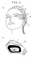
- the image pickup display apparatus 1 shown in FIG. 1 is an example in which a component block for image pickup and the display panels 2a, 2b are integrated to be worn by the user; however, as a device worn by the user, an image pickup apparatus 30 and a display apparatus 40 as shown in (a) and (b) of FIG. 2 can be conceivable.
- the image pickup apparatus 30 shown in (a) of FIG. 2 is worn on the temporal region of head with a predetermined mounting frame. And, so as to do image pickup with the user's field of vision as the direction of subject in the wearing state, the image pickup lens 3a and the light emitting block 4a are arranged toward the front. In addition, the microphone 6a for picking up external sound is arranged.
- this image pickup apparatus 30 having no display capabilities, provides an apparatus for taking a scene in the user's field of vision when worn on the user. It should be noted that, with the image pickup apparatus 30 such as this, various shapes, mounting structures, and component elements are possible as with the above-mentioned image pickup display apparatus 1.
- the display apparatus 40 shown in (b) of FIG. 2 is an example of a display apparatus of a wrist watch type, in which the display panel 2a is formed visually recognizable by the user in a state where the apparatus is worn on the wrist of the user with a wrist band.
- the display apparatus 40 of wrist watch type; however, it is supposed that the display apparatus 40 worn by carried by the user have various shapes and mounting structures.
- the display apparatus 40 may be a portable, small device that is carried by the user.
- the display apparatus 40 shown in FIG. 1 is possible that is of eyeglass type and can be carried by the user (an apparatus obtained by removing the image pick up capabilities from the image pickup display apparatus 1 shown in FIG. 1 ).
- the display apparatus 40 that can be carried portable by the user, not only a device dedicated to monitoring display but also such devices having display capabilities as a mobile phone, a portable game machine, a PDA (Personal Digital Assistant) may provide the display apparatus 40 of this example.
- a device dedicated to monitoring display but also such devices having display capabilities as a mobile phone, a portable game machine, a PDA (Personal Digital Assistant) may provide the display apparatus 40 of this example.
- a PDA Personal Digital Assistant
- a desktop type display apparatus In addition to devices that are worn or carried by the user, a desktop type display apparatus, a computer apparatus, a television receiver, and on-vehicle display monitor device may be used for the display apparatus 40 of this example.
- the image pickup apparatus 30 and the display apparatus 40 shown on (a) and (b) of FIG. 2 in a separate manner; however, a use form may be supposed in which the user wears both the image pickup apparatus 30 and the display apparatus 40 and uses them as an image pickup display apparatus based on these two devices.
- the image pickup apparatus 30 and the display apparatus 40 may execute data communication with each other for the display apparatus 40 to monitor images taken by the image pickup apparatus 30 or display images transmitted from an external device.
- the use of the image pickup display apparatus 1 and the display apparatus 40 are assumed for use by the user (human); however, the image pickup apparatus 30 is assumed for being worn by various moving bodies other than humans, moving bodies being of various kinds including humans.
- the image pickup apparatus 30 as shown in (a) of FIG. 2 is an example in which it is worn by a human and picks up a sight of field of vision of the human. However, it is conceivable that the image pickup apparatus 30 is mounted to moving bodies other than humans.
- Moving bodies other than humans may include creatures other than humans, ground moving devices, marine moving devices, submarine moving devices, air moving devices, and space moving devices, for example.
- Creatures other than humans may include birds, mammals, reptiles, amphibians, fishes, insects, and others.
- Ground moving devices may include power vehicles such as passenger cars, trucks, buses, taxis, and motor bikes, and man-powered vehicles such as bicycles, rickshaws, and toy cars.
- power vehicles such as passenger cars, trucks, buses, taxis, and motor bikes
- man-powered vehicles such as bicycles, rickshaws, and toy cars.
- Railroad vehicles such as electric trains and steam locomotives are also assumed.
- pleasure vehicles in amusement parks and work vehicles in factories and other facilities are supposed.
- unmanned moving bodies are possible.
- these moving bodies may include business or hobby robots and so-called radio-controlled toys.
- Marine moving bodies may include various types of ships, water motor bikes, surf boards, rowing boats, floats, and rafts.
- Submarine moving bodies may include submarines, submarine robots, and diving equipment such as aqualungs.
- Air moving bodies may include various types of airplanes, helicopters, gliders, parachutes, balloons, and kites.
- Space moving bodies may include rockets, space probes, and artificial satellites.
- the image pickup apparatus 30 may only be designed in shape and mounting structure suited for each moving body.
- the user of the image pickup display apparatus 1 or the display apparatus 40 can access another image pickup display apparatus 1 or the image pickup apparatus 30 as desired to see images taken by that another image pickup display apparatus 1 or the image pickup apparatus 30. Namely, the user of the image pickup display apparatus 1 or the display apparatus 40 can see, on his image pickup display apparatus 1 or the display apparatus 40, images representing a scene that can be seen by the sight in field of vision of another person or above-mentioned various moving bodies.
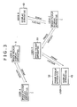
- FIG. 3 Exemplary systems forms configured to realize the above capabilities are shown in FIG. 3 , FIG. 4 , and FIG. 5 .
- FIG. 3 shows an example in which the image pickup display apparatus 1, the display apparatus 40, and the image pickup apparatus 30 each directly executes data communication as required.
- users A, B, and C wear the image pickup display apparatuses 1 as shown in FIG. 1 for example. It is also assumed that user D wear the display apparatus 40 as shown in (b) of FIG. 2 for example and user E wear the image pickup apparatus 30 as shown in (a) of FIG. 2 . Further, it is assumed that user F wear both the image pickup apparatus 30 shown in (a) of FIG. 2 and the display apparatus 40 shown in (b) of FIG. 2 , which function as an image pickup display apparatus.
- users A, B, C, D, and F having the image pickup display apparatuses 1 or the display apparatuses 40 can access another device as desired to see a sight in field of vision of any other users.
- user A specifies, from his image pickup display apparatus 1, the image pickup display apparatus 1 of user B to access thereto. Then, the image data being taken by the image pickup display apparatus 1 of user B is transmitted. The image pickup display apparatus 1 of user A receives this image data and outputs the received image data for display. Consequently, user A gets in a state where the sight in field of vision of user B can be seen.
- FIG. 3 shows a similar operation executed between user C and user D, user C and user E, and user E and user F.
- user D specifies, from his display apparatus 40, the image pickup display apparatus 1 of user C to request the transmission of the taken image data. Then, the requested image data is transmitted from the image pickup display apparatus 1 to the display apparatus 40 to be displayed at the display apparatus 40. Consequently, user D can see the sight in field of vision of user C.
- User E only wears the image pickup apparatus 30 having no display capabilities, so that user E cannot see field of vision of the other users.
- user E is positioned as a provider of images of field-of-vision sight.
- User C and user F can see the sight in field of vision of user E by specifying the image pickup apparatus 30 of user E.
- the image pickup apparatus 30 worn by various moving bodies other than the human mentioned above may be thought as positioned as an image provider as with the image pickup apparatus 30 of the user E.
- FIG. 4 shows the image pickup display apparatuses 1, the image pickup apparatuses 30, and the display apparatuses 40 owned by users A through F, in which these devices communicate with each other via a network 60.
- Each image pickup display apparatus 1 or display apparatus 40 accesses another image pickup display apparatus 1 or display apparatus 40 by the communication via the network 60, thereby requesting images. Then, the image data transmitted in response to the request is received and displayed.
- FIG. 3 is a system example in which the devices directly communicate with each other; for example, this example is suited for a system used in a comparatively narrow range in which direct communication is practicable, such as only inside sport facilities including succor and baseball parks, only inside a theme park, only inside an event arena, or only inside a particular district.
- the size of the range depends on the communication capabilities provided to the image pickup display apparatus 1 and so on; therefore, if access to other devices in wider range, worldwide for example, is required, it is suitable to execute mutual communication via the network 60 as shown in FIG. 4 .
- the network 60 may be a wide area network, such as the Internet; obviously, a narrow area network, such as a LAN (Local Area Network) is also possible.
- a wide area network such as the Internet
- a narrow area network such as a LAN (Local Area Network) is also possible.
- FIG. 5 shows the image pickup display apparatuses 1, the image pickup apparatuses 30, and the display apparatuses 40 owned by users A through F, which form a system in which each of these devices execute communication via a server apparatus 70 on the network 60.
- the server apparatus 70 communicates with the specified image pickup display apparatus 1 or the image pickup apparatus 30 to request the image and transfers the transmitted image data to the image pickup display apparatus 1 or the display apparatus 40. This allows the user of the image pickup display apparatus 1 or the display apparatus 40 to see the image taken by another image pickup display apparatus 1 or image pickup apparatus 30.
- a user can see the sight of field of vision of another user in a realtime manner (realtime herein does not consider a time lag caused by communication for example); however, it is also practicable for a user to see a past sight.
- images taken by the image pickup display apparatus 1 or the image pickup apparatus 30 are stored in the server apparatus 70, images taken by the image pickup display apparatus 1 or the image pickup apparatus 30 in the past can be provided to the display apparatus 40 and the image pickup display apparatus 1.
- the specification of the image pickup display apparatus 1 or the image pickup apparatus 30 can be directly executed by use of apparatus or user identification information; indirect specification is also practicable.
- the specification can be executed by use of the location, image pickup direction, elevation angle, altitude, and type of location of a location of image pickup, the moving speed information at the time of image pickup, the type of moving body, the performance of the image pickup display apparatus 1 or the image pickup apparatus 30, the image pickup state of the image pickup display apparatus 1 or the image pickup apparatus 30, or the contents of image pickup being executed.
- the image pickup display apparatus 1 or the display apparatus 40 can realize an operation of accessing the image pickup display apparatus 1 or the image pickup apparatus 30 that satisfies these specification conditions or the server apparatus 70 can realize an operation of searching for the image pickup display apparatus 1 or the image pickup apparatus 30 that satisfies these specification conditions for access in the system form shown in FIG. 5 .
- the following describes the exemplary configurations of the image pickup display apparatus 1, the image pickup apparatus 30, the display apparatus 40, and the server apparatus 70 with reference to FIG. 6 through FIG. 10 .
- a system controller 10 configured by a microcomputer having a CPU (Central Processing Unit), a ROM (Read Only Memory), a RAM (Random Access Memory), a nonvolatile memory block, and an interface block, provides a control block configured to control the entire image pickup display apparatus 1.
- the system controller 10 executes various operational processing and transfers control signals for example with each component block on the basis of programs held in the ROM and so on, thereby making each component block execute operations.
- an image pickup block 3 is arranged as a configuration for taking an image of the sight in the direction of the field of vision of the user.
- the image pickup block 3 has an image pickup optical system, an image pickup device block, and an image pickup signal processing block.
- the image pickup optical system in the image pickup block 3 has a lens system based on the image pickup lens 3a shown in FIG. 1 , a stop, a zoom lens, and a focus lens and a drive system configured to make the lens system execute a focus operation and a zoom operation.
- the image pickup device block in the image pickup block 3 has a solid-state image pickup device array for detecting an image pickup light obtained by the image pickup optical system to execute photoelectric conversion, thereby generating an image pickup signal.
- the solid-state image pickup device array is a CCD (Charge Coupled Device) sensor array or a CMOS (Complementary Metal Oxide Semiconductor) sensor array.
- the image pickup signal processing block in the image pickup block 3 has a sample hold/AGC (Automatic Gain Control) circuit for executing gain control and waveform shaping and a video A/D converter, thereby providing pickup image data that is digital data. Also, the image pickup signal processing block executes white balance processing, luminance processing, color signal processing, and anti-shake processing on the pickup image data.
- AGC Automatic Gain Control
- An image pickup operation is executed by the image pickup block 3 having these image pickup optical system, image pickup device block, and image pick up signal processing block, thereby obtaining an image data.
- the system controller 10 executes control of turning on/off each image pickup operation in the image pickup block 3, driving the zoom lens and the focus lens of the image pickup optical system, the sensitivity and frame rate of the image pickup device block, and setting of parameters and execution of the processing of the image pickup signal processing block.
- the pickup image data obtained by an image pickup operation by this image pickup block 3 can be supplied to the display block 2, a storage block 25, and a communication block 26 via an image processing block 15.
- the image processing block 15 executes processing of converting pickup image data into a predetermined image data format and predetermined signal processing for monitor-displaying the image data on the display block 2.
- the signal processing for monitor-displaying images on the display block 2 includes luminance level adjustment, color correction, contrast adjustment, sharpness (highlighting) adjustment, screen partitioning processing, character image synthesis processing, generation of zoom-in or zoom-out images, and image effect processing such as mosaic image/luminance inversion image/soft focus/partial highlighting in image/variation of color atmosphere of entire image.
- the image processing block 15 transfers image data between the image pickup block 3, the display block 12, the storage block 25, and the communication block 26. Namely, the image processing block 15 executes the processing of supplying pickup image data from the image pickup block 3 to the display block 2, the storage block 25, and the communication block 26, the processing of supplying the image data reproduced in the storage block 25 to the display block 2, and the processing of supplying the image data received through the communication block 26 to the display block 2.
- the display block 2 is arranged.
- This display block 2 has display panel blocks 2a, 2b that is, for example, liquid crystal panels described above, and a display drive block for driving the display panel blocks 2a, 2b.
- the display drive block is configured by a pixel drive circuit for displaying an image signal supplied from the image processing block 15 onto the display panels 2a, 2b that are liquid crystal panels for example. Namely, in the display panels 2a, 2b, the pixels arranged in a matrix are applied with drive signals based on video signal with predetermined horizontal/vertical drive timings, thereby executing display.
- This processing allows the displaying on the image pickup block 3 as an image pickup monitor, the displaying an reproduced image reproduced in the storage block 25, and the displaying of a received image received through the communication block 26 on the display panels 2a, 2b.
- the display drive block can control the transmissivity of each pixel on the display panels 2a, and 2b so as to make the panels in a through state, namely, transparent state, or translucent state.
- the system controller 10 executes control of turning on/off (through) of a display operation in this display block 2, the commanding of processing parameters to the image data to be displayed, control of screen area setting, and the commanding of generating characters.
- the image pickup display apparatus 1 has an audio input block 6, an audio processing block 16, and an audio output block 5.
- the audio input block 6 has microphones 6a, 6b shown in FIG. 1 and a microphone amplifier block for amplifying the audio signals obtained by the microphones 6a, 6b, and an A/D converter, thereby outputting audio data.
- the audio data obtained in the audio input block 6 is supplied to the audio processing block 16.
- the audio processing block 16 controls the transfer of audio data. Namely, the audio processing block 16 supplies the audio data obtained in the audio input block 6 to the audio output block 5, the storage block 25, and the communication block 26. Alternatively, the audio processing block 16 supplies the audio data reproduced in the storage block 25 and the audio data received by the communication block 26 to the audio output block 5.
- the audio processing block 16 executes the processing of volume adjustment, tone quality adjustment, and sound effect processing.
- the audio output block 5 has the pair of earphone speakers 5a shown in FIG. 1 and an amplifier circuit and a D/A converter for that pair of earphone speakers 5a.
- the audio data supplied from the audio processing block is converted through the D/A converter into an analog audio signal and is amplified through the amplifier circuit to be outputted from the earphone speaker 5a as sound. Consequently, the user can hear external sound and sound based on the audio data reproduced in the storage block 25 and the audio data received by the communication block 26.
- the audio output block 5 may be configured by a so-called bone conduction speaker.
- the storage block 25 is a member to record and reproduce image data (and audio data) on a predetermined recording media.
- the storage block 25 is realized as a HDD (Hard Disk Drive).
- recording media may include solid-state memories such as a flash memory, a memory card incorporating a solid-state memory, an optical disk, a magneto-optical disk, and a hologram memory and the storage block 25 may only be configured so that recording and reproducing can be executed in accordance with recording media used.
- this storage block 25 records the image data (and audio data) obtained by an image pickup operation on recording media. Namely, the image data supplied through the image processing block 15 and the audio data supplied through the audio processing block 16 are encoded for recording to recording media and the encoded data are recorded to recording media.
- the storage block 25 can reproduce the image data and the audio data that are recorded.
- the reproduced image data is supplied to the display block 2 through the image processing block 15 and audio data is supplied to the audio output block 5 through the audio processing block 16. Further, the reproduced image data/audio data can also be supplied to the communication block 26 as data to be transmitted to external devices.
- processing is executed to specify another image pickup display apparatus 1 or image pickup apparatus 30 on a map; in this case, map image is displayed on the display block 2.
- map database be stored in the storage block 25 for the displaying of this map image.
- a storage block for storing the map database may be arranged outside the storage block 25.
- the system controller 10 can execute map search and map display processing by use of a map database.
- the communication block 26 executes transfers data with external devices.
- External devices may include another image pickup display apparatus 1, another image pickup apparatus 30, the display apparatus 40, the server apparatus 70.
- This communication block 26 may be configured to execute network communication via near-distance wireless communication for a network access point for example on the basis of wireless LAN or Bluetooth or may execute direct wireless communication with external devices having corresponding communication capabilities.
- the pickup image data taken by the image pickup block 3 is supplied via the image processing block 15.
- the audio data obtained in the audio input block 6 is supplied via the audio processing block 16.
- the communication block 26 can encode these image data and audio data for communication and modulate the encoded data for wireless transmission for the transmission to external devices. Namely, the communication block 26 can transmit the realtime image data/audio data currently taken and picked up by the image pickup display apparatus 1 to external devices (another image pickup display apparatus 1, the display apparatus 40, and the server apparatus 70).
- the communication block 26 can encode, for communication, the image data and audio data reproduced in the storage block 25 and modulate the encoded data for wireless transmission for the transmission to external devices.
- the communication block 26 receives the image data/audio data supplied from external devices (another image pickup display apparatus 1, the image pickup apparatus 30, and the server apparatus 70) and demodulates the received data to supply the demodulated data to the image processing block 15 and the audio processing block 16. In this case, the received image and audio are outputted by the display block 2 and the audio output block 5.
- the image data/audio data received by the communication block 26 may be supplied to the storage block 25 for recording to recording media.
- the image pickup display apparatus 1 has a lighting block 4 and a lighting control block 14.
- the lighting block 4 is composed of a light emitting block 4a shown in FIG. 1 and FIG. 2 and a lighting circuit for driving the lighting block 4a (LED for example).
- the lighting control block 14 makes the lighting block 4 execute a lighting operation on the basis of a command from the system controller 10.
- Mounting the light emitting block 4a in the lighting block 4 as shown in FIG. 1 or FIG. 2 allows the lighting block 4 to execute a lighting operation with the image pickup lens 3a in the direction of a subject.
- an operation input block 11 is provided for the user to execute operations.
- the operation input block 11 may have controls such as keys and dials for example and be configured so as to detect a user operation of a key and so on or a user's intentional behavior.
- these controls may be formed to execute a power on/off operation, image pickup related operations (for example, a zooming operation and a signal processing instructing operation), display related operations (for example, a display contents selecting operation and a display adjusting operation), and an operation for specifying an external device that will be described later.
- image pickup related operations for example, a zooming operation and a signal processing instructing operation
- display related operations for example, a display contents selecting operation and a display adjusting operation
- an operation for specifying an external device that will be described later.
- an acceleration sensor In the case of detecting a user's behavior, the installation of an acceleration sensor, an angular velocity sensor, a vibration sensor, and a pressure sensor is possible.
- the tapping by the user on the image pickup display apparatus 1 from one side may be detected with an acceleration sensor and a vibration sensor for example and, when the lateral acceleration exceeds a certain value, for example, the system controller 10 may recognize the tapping as a user's operation.
- a user's head swiveling or neck shaking operation may be detected with an acceleration sensor and an angular velocity sensor for the system controller 10 to recognize a user's operation.
- pressure sensors may be arranged on the left and right sides (portions equivalent to the bows of a pair of eyeglasses) and so on of the image pickup display apparatus 1 and, when the user presses the right side with a finger, a zooming operation in the telescopic direction may be effected, while, when the user presses the left side with a finger, a zooming operation in the wide-angle direction may be effected.
- a configuration as a biological sensor may be provided in which user's biological information is detected to recognize as operation input.
- the biological information includes pulse rate, heart rate, electrocardiogram information, myoelectric and aspiration information (for example, breath speed, depth, and amount of ventilation), perspiration, GSR (Galvanic Skin Reflex), blood pressure, blood oxygen level, skin surface temperature, brain waves (for example, ⁇ wave, ⁇ wave, ⁇ wave, and ⁇ wave), blood flow change, and eye state.
- the system controller 10 may be configured to recognize the biological sensor detected information as user operation input. For example, an eye movement (a change in eyesight direction or a wink) may be assumed as a user's intentional behavior; for example, when three winks made by the user is detected, it may be determined to be a particular operation input. Further, it is practicable to detect the wearing or unwearing of the image pickup display apparatus 1 on the basis of the above-mentioned detection of biological information or the wearing by a particular user and, for the system controller 10, execute power on/off in accordance with that detection.
- an eye movement a change in eyesight direction or a wink
- the operation input block 11 supplies the information thus obtained as a control, an acceleration sensor, an angular velocity sensor, a vibration sensor, a pressure sensor, and a biological sensor to the system controller 10, which detects user operations on the basis of these items of information.
- the image pickup display apparatus 1 also has a position detecting block 12.
- the position detecting block 12 is a GPS receiving block for example.
- the GPS receiving block receives radio wave from a GPS (Global Positioning System) artificial satellite and outputs latitude and longitude information as a current position to the system controller 10.
- GPS Global Positioning System
- This position detecting block 12 is provided as for an image pickup display apparatus 1 or a display apparatus 40 to specify another image pickup display apparatus 1 or image pickup apparatus 30 by position in the cases of system operation examples III and IV to be described later.
- the system controller 10 executes the processing of transmitting the positional information (longitude and latitude) detected by the position detecting block 12 from the communication block 26 to the server apparatus 70 on a periodical basis, for example.
- WiFi Wireless Fidelity
- positional information services provided by a mobile phone carrier may be used.
- An image pickup apparatus 30 shown in FIG. 7 has a configuration in which the display block 2 and the audio output block 5, which are the image and audio output systems, of the image pickup display apparatus 1 shown in FIG. 6 are eliminated.
- this image pickup apparatus 30 can be worn by the user as shown in FIG. 2 and, as carried by various moving bodies as described above, take images by the image pickup block 3 to transmit pickup image data from a communication block 26 to an external device or record to a storage block 25.
- a system controller 10 executes control of an image pickup operation, a communication operation, a recording operation, and so on.
- FIG. 8 An exemplary configuration of a display apparatus 40 is as shown in FIG. 8 .
- the image pickup apparatus 40 shown in FIG. 8 has a configuration in which the image pickup block 3 and the audio input block 6, which provide the image pickup and audio input functions in the image pickup display apparatus 1 shown in FIG. 6 , are eliminated.
- the lighting block 4 and the lighting control block 14 that are auxiliary to image pickup are not arranged, either.
- the position detecting block 12 arranged for the purpose of specifying an image provider may not be provided, either.
- This display apparatus 40 is a device that is worn by the user in a form shown in (b) of FIG. 2 , owned by the user, or owned by the user as installed in the home or on the car for example, receiving image data/audio data through a communication block 26 from an external device.
- the received image data/audio data is outputted from a display block 2 and a audio input block 6 or recorded to a storage block 25.
- a system controller 10 executes control of a communication operation, a display operation, an audio output operation, a recording operation, and so on.
- an exemplary configuration as shown in FIG. 9 is possible as the image pickup apparatus 30 and the display apparatus 40.
- the image pickup apparatus 30 is given a substantially the same configuration of that of the image pickup display apparatus 1 shown in FIG. 6 .
- no display block 2 is arranged in the image pickup apparatus 30; a transmitting block 27 is provided instead.
- the transmitting block 27 encodes the image data to be supplied from the image processing block 15 for display monitoring, so as to be transmitted to the display apparatus 40. Then the encoded data is transmitted to the display apparatus 40.
- the display apparatus 40 also has a receiving block 41, a display control block 42, and a display block 2.
- the receiving block 41 executes data communication with a transmitting block 21 of the image pickup apparatus 30. Then, the receiving block 41 receives image data transmitted from the image pickup apparatus 30 to decode the received image data.
- the image data decoded in the receiving block 41 is supplied to the display control block 42.
- the display control block 42 executes signal processing, screen partitioning, and character synthesis for displaying image data to generate an image signal for displaying, supplying the generated image signal to a display block 2 having a display panel 2a that is a liquid crystal panel.
- the pixels arranged in a matrix of the display panel 2a are applied with drive signals based on video signal with predetermined horizontal/vertical drive timings, thereby executing display.
- the user wearing the image pickup apparatus 30 and the display apparatus 40 like user F shown in FIG. 3 , FIG. 4 , and FIG. 5 can use these apparatuses in the same manner as the image pickup display apparatus 1.
- FIG. 10 shows, in FIG. 10 , an exemplary configuration of the server apparatus 70 shown in FIG. 5 .
- the server apparatus 70 has a server control block 72, a network storage block 71, a communication block 73, a camera information managing block 74, and a map database 75.
- the network storage block 71 realized by a HDD for example, is used to temporarily buffer image data/audio data transmitted from the image pickup apparatus 30 or image pickup display apparatus 1 via a network 60 in transferring these data to the display apparatus 40 or the image pickup display apparatus 1 or store image data/audio data transmitted from the image pickup apparatus 30 or the image pickup display apparatus 1 via the network 60 for a predetermined period of time, for example.
- the communication block 73 execute data communication between the image pickup display apparatus 1, the image pickup apparatus 30, and the communication block 26 of the display apparatus 40 via the network 60.
- the server control block 72 executes control necessary for operations as the server apparatus 70. To be more specific, the server control block 72 executes communication operations between the image pickup display apparatus 1, the image pickup apparatus 30, and the display apparatus 40 and the processing of storing image data/audio data into the network storage block 71.
- the camera information managing block 74 and the map database 75 provide members necessary executing system operation examples III through VII, and IX to be described later.
- the camera information managing block 74 manages, in response to a system operation to be executed, the current position, image pickup direction (orientation), elevation angle, and moving speed of the image pickup display apparatus 1 and the image pickup apparatus 30, manages the performance (specifications) and image pickup operation state of the image pickup display apparatus 1 and the image pickup apparatus 30, and manages the types of moving bodies.
- a camera information management table as shown in (a) of FIG. 16 to be described later is used to manage the positional information transmitted from time to time from the image pickup display apparatus 1 and the image pickup apparatus 30. Also, by matching against the map information stored in the map database 75, the current positions of the image pickup display apparatus 1 and the image pickup apparatus 30 can be managed in more detail.
- the configurations of the image pickup display apparatus 1, the image pickup apparatus 30, the display apparatus 40, and server apparatus 70 have been shown just as examples. It is obvious that the addition or deletion of various types of component elements is possible in accordance with actually practiced system operation examples and functions. Further, it is obvious that these configurations are subject to variation in accordance with the types of moving bodies on which the image pickup apparatus 30 and the image pickup display apparatus 1 are installed (mounted) and the types of the display apparatus 40 (for example, wristwatch type, portable type, and stationary type).
- system operation example I is described in which, as shown in FIG. 3 or FIG. 4 , the image pickup display apparatus 1 or the display apparatus 40 executes communication with another image pickup display apparatus 1 or image pickup apparatus 30 to acquire and display image data obtained from another image pickup display apparatus 1 or image pickup apparatus 30 mentioned above.
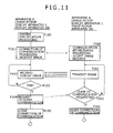
- FIG. 11 shows the processing of apparatus A and apparatus B as system operation example I.
- Apparatus A denotes the image pickup display apparatus 1 or the display apparatus 40 shown in FIG. 3 or FIG. 4 .
- Apparatus B denotes the image pickup display apparatus 1 or the image pickup apparatus 30 shown in FIG. 3 or FIG. 4 .
- apparatus A is a device on the side in which apparatus A is used by a user to receive an image taken by another moving body and the received image is displayed, being equivalent to "display apparatus” as referred to in claims of the present invention.
- the processing by apparatus A shown in FIG. 11 is the control processing by the system controller 10 of the image pickup display apparatus 1 or the display apparatus 40; therefore, the processing by a system controller 10 of this apparatus A includes "specification processing,” “image request transmission processing,” and “display processing” as referred to in claims of the present invention.
- apparatus B is a device on the side in which an image is provided in response to the specification from apparatus A, or a device worn/carried on human, creature, vehicle, or other moving bodies mentioned above, being equivalent to "image pickup apparatus” as referred to in claims attached hereto.
- the processing by apparatus B shown in FIG. 11 is the control processing by the system controller 10 of the image pickup display apparatus 1 or the image pickup apparatus 30; therefore, the processing by a system controller 10 of apparatus B includes "transmission control processing" as referred to in claims of the present invention.
- step F100 camera specification processing is first executed as step F100.
- the user of apparatus A executes an operation of specifying a certain apparatus B as another image pickup display apparatus 1 or image pickup apparatus 30.
- the user may enter the camera ID (information for individually identifying the image pickup display apparatus 1 or image pickup apparatus 30) of above-mentioned another apparatus B or enter the user ID (information on user identification such as user code or user name) of the user (for example, a friend or an image service provider) owning above-mentioned another apparatus B.
- the camera ID information for individually identifying the image pickup display apparatus 1 or image pickup apparatus 30
- the user ID information on user identification such as user code or user name of the user (for example, a friend or an image service provider) owning above-mentioned another apparatus B.
- the system controller 10 of apparatus A may list apparatuses B accessible from that apparatus A onto a display block 2 to let the user select any apparatus B from the displayed list; the user executes a selecting operation accordingly, thereby establishing camera ID, user ID, and so on.
- the system controller 10 of the apparatus A sets the apparatus B indicated by the specified camera ID or user ID as an access destination.
- the information may be taken out that identifies the mate of communication, such as so-called telephone number, electronic mail address, or URL (Uniform Resource Locator), communication destination code dedicated to local area, and so on.
- the system controller 10 may hold, in a nonvolatile memory or the like internal thereto, the information for identification communication destinations in correspondence with camera ID and so on.
- Ranges (ranges of specifiable devices) of apparatuses B accessible from apparatus A are various.
- group IDs are set among groups of friends for example to execute image data communication between the image pickup display apparatus 1, the image pickup apparatus 30, and the display apparatus 40 having the same group ID
- another image pickup display apparatus 1 and another image pickup apparatus 30 in the group in which the apparatus A itself is included as seen therefrom may become the apparatus B.
- the image pickup apparatus 30 for example installed by that service provider may become apparatuses B as seen from the apparatus A.
- the system controller 10 of the apparatus A executes the camera specification processing including the detection of user input and the displaying for input in step F100 to establish the specification of a certain apparatus B and then the system controller 10 of the apparatus A executes communication connection processing on the specified apparatus B in step F101. Namely, the system controller 10 of the apparatus A executes communication access to the apparatus B specified by the camera specification processing, thereby establishing the communication connection with the apparatus B. On the side of the apparatus B, communication establishment processing is executed in response to the access from the apparatus A in step F200. Then, when the communication connection has been established, the side of the apparatus A transmits image request information to the apparatus B. The apparatus B accepts the image request.
- the apparatus B executes image transmission processing in response to the image request in step F201. Namely, the system controller 10 of the apparatus B transmits the image data obtained by image pickup in the image pickup block 3 and the audio data picked up by the audio input block 6 to the apparatus A from the communication block 26. It should be noted that, on the side of the apparatus B, the image pickup may have been executed at a point of time before the acceptance of the image request or the image pickup may start in response to the image request acceptance.
- the system controller 10 of the apparatus A supplies the image data (and the audio data) received and demodulated by the communication block 26 to the image processing block 15 and the audio processing block 16, thereby executing the display output on the display block 2 and the audio output from the audio output block 5.
- the system controller 10 of the apparatus A continuously executes the display output (and the audio output) of the received data until an end is determined in step F103. Also, the apparatus B continues the image pickup and the transmission of the taken image data (and audio data) until the clear of communication is requested by the apparatus A.
- the apparatus A determines in step F103 whether the image displaying has ended or not. For example, if the user executes an operation of ending the displaying through the operation input block 11, it is determined that the displaying has ended. Also, it is possible to automatically ending the reception and displaying after a predetermined duration of time. Although not shown in the flowchart of FIG. 11 , processing may be executed in which the apparatus B instructs the apparatus A to end the above-mentioned execution.
- step F103 If the end is found in step F103 according to a user operation or another ending condition, the system controller 10 of the apparatus A goes to step F104 to transmit a communication clear request from the communication block 26 to the apparatus B.
- step F202 Confirming the reception of the communication clear request as step F202, the system controller 10 of the apparatus B goes to step F203.
- system controller 10 of the apparatus A and the system controller 10 of the apparatus B execute the clearing of communication connection in step F105 and step F203, respectively, thereby ending the sequence of system operations.
- the user of the apparatus A can specify a certain apparatus B as desired to see a sight obtained by the specified apparatus B on the apparatus A worn or owned by him.
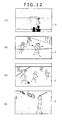
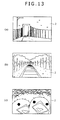
- FIG. 12 Examples of sights that can be seen by the user of apparatus A are shown in FIG. 12 and FIG. 13 .
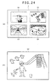
- the user of the apparatus A specify the image pickup display apparatus 1 or the image pickup apparatus 30 worn or owned by a friend. Then, the user of the apparatus A can see a field-of-vision sight seen by the friend. For example, (a) of FIG. 12 shows that a sight seen by the friend in a sightseeing area or a resort is displayed on the display block 2 of the image pickup display apparatus 1 or the display apparatus 40 that is the apparatus A of the user. Consequently, the user can enjoy a sight of a remote resort for example.
- the user of the apparatus A stands at a location in an athletic festival arena and the location of the user hardly gives a good command of the view of competitions, the user can specify the apparatus B worn by a friend having a good command of view to allow the user of the apparatus A to see sights as seen by the friend as shown in (b) of FIG. 12 .
- the user of the apparatus A is in a facility and specifies the apparatus B worn by another person or some moving body in that facility, the user can see sights seen by that another person or some moving body.
- the user of the apparatus A be in the auditorium of a succor stadium.
- the apparatus B worn by a succor judge be specifiable by the user of the apparatus A. Then, the user of the apparatus A can see sights seen by the judge as shown in (c) of FIG. 12 while the user of the apparatus A is sitting in the auditorium.
- FIG. 12 shows a sight of a golf practice.
- a sight of swinging of the user of the apparatus A be seen by the user of the apparatus B from the front.
- the user of the apparatus A can see an image representing his swinging form taken by the apparatus B and displayed on the display block 2 of the apparatus A worn by him.
- the user of the apparatus A can swing while seeing his swinging form, which is useful in checking his swinging forms.
- FIG. 13 shows an exemplary image in which the image pickup display apparatus 1 or the image pickup apparatus 30 as the apparatus B is mounted on a car.
- the user of the apparatus A can specify a certain apparatus B mounted on a car to receive the image data transmitted from the apparatus B whereby the user of the apparatus A can see sights seen on that car on the apparatus A worn or owned by the user.
- FIG. 13 shows an exemplary image in which the image pickup display apparatus 1 or the image pickup apparatus 30 as apparatus B is mounted on a railroad vehicle.
- the user of apparatus A can specify apparatus B mounted on a railroad vehicle to receive image data transmitted from apparatus B, thereby seeing sights seen from that railroad vehicle on apparatus A worn or owned by the user thereof.
- FIG. 13 shows an exemplary image in which the image pickup apparatus 30 as apparatus B is mounted on a bird.
- the user of apparatus A can specify apparatus B mounted on a bird to receive image data transmitted from apparatus B, thereby seeing sights in field of vision of that bird (for example, a sight in a nest in this case) on apparatus A worn or owned by the user thereof.
- the user of apparatus A can see, as desired, sights seen from other people, other moving devices, other creatures, and various other moving bodies. Namely, the user of apparatus A can expand his vision on a pseudo basis to see sights seen from moving bodies other than the user of apparatus A.
- This is a processing example in which image data is transmitted from apparatus B to apparatus A via the server apparatus 70 as shown in FIG. 5 .
- Operations of the server apparatus 70 shown in FIG. 14 may be considered as the processing of the server control block 72 shown in FIG. 10 .
- step F110 On the side of apparatus A, camera specification processing is first executed as step F110.
- the camera specification processing is the same as that of above-mentioned step F100 shown in FIG. 11 .
- the system controller 10 of apparatus A After entering the specification of a certain apparatus B by the camera specification processing of step F110, the system controller 10 of apparatus A next accesses the server apparatus 70 in step F111. Namely, a communication connection state with the server apparatus 70 is established. Then, at this moment, image request information and camera specification information (for example, camera ID or user ID) indicative of the specified apparatus B are transmitted to the server apparatus 70.
- image request information and camera specification information for example, camera ID or user ID
- the server control block 72 of the server apparatus 70 establishes communication connection with apparatus A to accept the image request and the camera specification information in step S310. Then, the server control block 72 requests the particular apparatus B indicated by the camera specification information for communication connection, thereby establishing communication connection. Then, the server control block 72 notifies the particular apparatus B of the image request from apparatus A.
- the system controller 10 of apparatus B executes the processing of providing communication connection state in response to the connection request from the server apparatus 70 in step F210, thereby starting communication and accepting the image request.
- image transmission processing is executed in response to the image request in step F211.
- the system controller 10 of apparatus B transmits image data obtained by image pickup in the image pickup block 3 and audio data picked up by the audio input block 6 to the server apparatus 70 from the communication block 26.
- step S112 the reception and displaying of the image data transmitted from apparatus B via the server apparatus 70 are executed.
- the system controller 10 of apparatus A supplies the image data (and the audio data) received and demodulated by the communication block 26 to the image processing block 15 and the audio processing block 16, thereby executing display output on the display block 2 and audio output on the audio output block 5.
- the system controller 10 of apparatus A continuously executes this display output (and audio output) of the received data until an end is determined in step F113. Also, in apparatus B, until a communication clear request comes from apparatus A, the image pickup and the transmission of the taken image data (and audio data) are continued.
- the system controller 10 of apparatus A determines in step F113 whether or not image displaying is ended and, if the end is determined in accordance with a user operation or an end condition, goes to step F114 to transmit a communication clear request from the communication block 26 to the server apparatus 70.
- the server apparatus 70 is continuing the transfer processing of step F311 until the communication clear request is received. Then, upon reception of the communication clear request, the server apparatus 70 goes from step F312 to F313 to transmit a communication clear instruction to apparatus B.
- step F212 Upon confirmation of the reception of the communication clear instruction as step F212, the system controller 10 of apparatus B goes to step F213.
- step F105 the system controller 10 of apparatus A and, in step F203, the system controller 10 of apparatus B execute the processing of clearing the communication connection with the server apparatus 70, respectively.
- the server control block 72 of the server apparatus 70 ends the communication between apparatus A and apparatus B and the server processing in step F314. Thus, the system operation comes to an end.
- This system operation executed via the server apparatus 70 also allows the user of apparatus A to specify a certain B as desired, thereby seeing sights obtained by the specified apparatus B on the apparatus A worn or owned by the user of apparatus A. For example, images of sights illustrated in FIG. 12 and FIG. 13 can be seen.
- system operation example III is a processing example in which, like the above-mentioned system operation example II shown in FIG. 14 , image data is transmitted from apparatus B to apparatus A via the server apparatus 70, being an example in which, by specification a position from the side of apparatus A, a certain apparatus B can be specified.
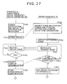
- step F120 On the side of apparatus A, positional specification processing is first executed as step F120.
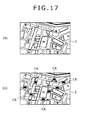
- the system controller 10 of apparatus A executes map displaying by use of a map database stored in the storage block 25 or the like. Also, in accordance with a user operation, search for a certain region on map and scroll displaying are executed. Consequently, the user can see map images of a particular district and region on the display block 2.
- the system controller 10 changes districts and scales to be displayed, thereby displaying a map image of a certain district as shown in (a) of FIG. 17 .
- positional specification information is generated. For example, positional specification information including values of the longitude and latitude of the specified point is generated.
- the system controller 10 of apparatus A next accesses the server apparatus 70 in step F121. Namely, a communication connection state is established with the server apparatus 70. Then, at this moment, the image request information and the positional specification information are transmitted to the server apparatus 70.
- the server control block 72 of the server apparatus 70 establishes communication connection with apparatus in step F320 and accepts the image request and the positional specification information.
- step F321 search is executed for an apparatus B (the image pickup display apparatus 1 or the image pickup apparatus 30) located near a particular position indicated by the positional specification information at that point of time.
- all the image pickup display apparatuses 1 and image pickup apparatuses 30 that can provide image supply sources be each sequentially or periodically transmitting own current positional information (longitude and latitude) to the server apparatus 70.
- the camera information managing block 74 manages the current positional information by relating with that camera ID for each image pickup display apparatus 1 and image pickup apparatus 30.
- the camera information managing block 74 has a camera information management table as shown in (a) of FIG. 16 .
- This camera information management table is a table recording current positional information (CP1, CP2%) corresponding to camera IDs (CM001, CM002).
- step F321 for the longitude and latitude contained in the positional specification information, the server control block 72 makes the camera information managing block 74 search for the image pickup display apparatus 1 or the image pickup apparatus 30 currently located near, thereby identifying certain one image pickup display apparatus 1 or image pickup apparatus 30 as apparatus B.
- the server control block 72 requests that apparatus B for communication connection in step F322, executing the processing of establishing communication connection. And the server control block 72 notifies the apparatus B of the image request from apparatus A.
- the server control block 72 notifies apparatus A of the inability to search for a corresponding apparatus B and therefore the inability to provide images.
- the side of apparatus A represents the inability of image provision to the user and ends the processing.
- the system controller 10 of the certain apparatus B that received the connection request by the processing of the server apparatus 70 in step F322 executes the processing of providing a communication connection state in response to that connection request in step F220, starting communication and, at the same time, accepting the image request.
- step F221 image transmission processing is executed in step F221 in response to the image request.
- the system controller 10 of apparatus B transmits the image data obtained by the image pickup in the image pickup block 3 and the audio data picked up by the audio input block 6 to the server apparatus 70 from the communication block 26.
- the image data (and the audio data) transmitted from the apparatus B is transferred to the apparatus A as the processing of step F323.
- step F122 On the side of apparatus A, the reception and displaying of the image data transmitted from the apparatus B via the server apparatus 70 are executed in step F122. Namely, the system controller 10 of apparatus A supplies the image data (and the audio data) received and demodulated by the communication block 26 to the image processing block 15 and the audio processing block 16, thereby executing the display output on the display block 2 and the audio output on the audio output block 5.
- the system controller 10 of apparatus A continuously executes this data display output (and the audio output) of the received data until an end is determined in step F123. Also, in apparatus B, until a communication clear request comes from apparatus A, the image pickup and the transmission of the taken image data (and audio data) are continued.
- the system controller 10 of apparatus A determines in step F123 whether or not image displaying is ended and, if the end is determined in accordance with a user operation or an end condition, goes to step F124 to transmit a communication clear request from the communication block 26 to the server apparatus 70.
- the server apparatus 70 is continuing the transfer processing of step F323 until the communication clear request is received. Then, upon reception of the communication clear request, the server apparatus 70 goes from step F324 to F325 to transmit a communication clear instruction to apparatus B.
- step F222 Upon confirmation of the reception of the communication clear instruction as step F222, the system controller 10 of apparatus B goes to step F223.
- step F125 the system controller 10 of apparatus A and, in step F223, the system controller 10 of apparatus B execute the processing of clearing the communication connection with the server apparatus 70, respectively.
- the server control block 72 of the server apparatus 70 ends the communication between apparatus A and apparatus B and the server processing in step F326. Thus, the system operation comes to an end.
- the user of apparatus A can see sights obtained by the specified apparatus B on the apparatus A worn or owned by the user of apparatus A. For example, images of sights illustrated in FIG. 12 and FIG. 13 can be seen.
- specifying positions is suitable when the user wants to check a current sight of a particular region. For example, by specifying a certain road, an actual congestion status can be known in detail by seeing sights of congestion situations near the specified road or the degree of congestion near an certain event arena can be checked by seeing as sights. Also, by seeing the current situation of a certain tourist spot, how much leaves have been turned red or the weather condition can be checked as actual sights.
- a certain position is specified on a map; it is also practicable for the user of apparatus A to enter a particular geographic name and address and transmit the entered geographic name and address to the server apparatus 70 as positional specification information without displaying a map.
- the position may be identified (for example, the identification of the longitude and latitude) from the map database 75 to search for the apparatus B near the position concerned.
- unspecified position the type of a place
- unspecified information such as “mountain,” “beach,” “forest district,” “over sea,” “in sea,” or “sky” is used for positional specification information.
- search can be executed for an apparatus B at the corresponding position.
- information for specifying the contents other than positional information or information for specifying two or more items of specification contents may be generated.
- the specification information may include orientation information as an image pickup direction, elevation angle information as an image pickup direction, altitude angle of image pickup place, and moving speed information of moving body at the time of image pickup.
- a position can be specified on a map image as shown in (a) of FIG. 7 and, at the same time, an orientation as an image pickup direction from that position can be specified.
- orientation may be made in east, west, south, north, south east, south west, north west, north east, east south east, south south east, south south west, south south west, west north west, north north west, north north east, east north east, or an orientation may be entered by pointing on a map.
- the apparatus A transmits positional information and orientation information to the server apparatus 70 as specification information.
- the camera information managing block 74 executes management/search by use of a camera information management table as shown in (b) of FIG. 16 .
- the camera information management table is a table recording current positional information (CP1, CP2%) and current image pickup orientations (for example, W: West, SSW: South South West, NE: North East, etc.) corresponding to camera IDs (CM001, CM002).
- all the image pickup display apparatuses 1 and the image pickup apparatuses 30 that can provide image supply sources be each sequentially or periodically transmitting own current positional information (longitude and latitude) and image pickup direction information to the server apparatus 70.
- the image pickup display apparatus 1 and image pickup apparatus 30 have each an orientation sensor in the position detecting block 12 for example, thereby having to detect image pickup directions too.
- the server apparatus 70 every time current positional information and orientation information are received from each image pickup display apparatus 1 or image pickup apparatus 30, the current positional information and the current image pickup direction information corresponding to the camera ID of the image pickup display apparatus 1 or image pickup apparatus 30 that is the transmission source is updated on this camera information management table, thereby grasping the current positions and image pickup directions of all the subject image pickup display apparatuses 1 or image pickup apparatuses 30.
- search can be executed for the corresponding image pickup display apparatus 1 or image pickup apparatus 30 as the corresponding apparatus B by referencing the camera information management table, thereby transferring an image from the corresponding apparatus B to the apparatus A in the above-mentioned same processing as that shown in FIG. 15 .
- Elevation angle information as an image pickup direction, altitude information of image pickup place, and moving speed information of moving body at the time of image pickup can be handled in the same manner.
- an elevation angle sensor, an altitude sensor, and a velocity sensor are arranged in the image pickup display apparatus 1 and the image pickup apparatus 30 and detection information from these sensors is made ready for sequential transmission to the server apparatus 70, thereby allowing the server apparatus 70 to grasp the elevation angle, altitude, and moving speed on the camera information management table for each apparatus B.
- specifying elevation angle, altitude, and moving speed from the side of apparatus A allows the server apparatus 70 to search for a corresponding apparatus B, thereby transferring an image to the apparatus A in the same processing as that shown in FIG. 15 .
- the server apparatus 70 sequentially updates and manages positional information, orientation information as image pickup direction, elevation angle information as image pickup direction, altitude information at image pickup place, and moving speed information of moving body at the time of image pickup for each image pickup display apparatus 1 and the image pickup apparatus 30, a system operation is supposed in which positional information, orientation information as image pickup direction, elevation angle information as image pickup direction, altitude information at image pickup place, and moving speed information of moving body at the time of image pickup are used individually or in combinations as specification information.
- system operation example IV is a processing example in which image data is transmitted from apparatus B to apparatus A via the server apparatus 70 in the same manner as system operation example III shown in FIG. 15 , being an example in which, by specifying camera specifications from apparatus A, a certain apparatus B can be specified.
- camera specifications processing is first executed as step F130.
- the camera specifications are items associated with the performance of the image pickup display apparatus 1 and the image pickup apparatus 30, including image pickup frame rate, resolution, the effective number of pixels of image pickup device, and image compression scheme, for example.
- the system controller 10 of apparatus A displays a camera specifications select screen on the display block 2 to let the user of apparatus A specify desired camera specifications. It should be noted that also possible is a specification input scheme for specifying a model name having desired camera specifications.
- step F131 the system controller 10 of apparatus A accesses the server apparatus 70. Namely, a communication connection state is established with the server apparatus 70. And, at this moment, the server apparatus 70 is notified of image request information and camera specifications specifying information.
- the server control block 72 of the server apparatus 70 establishes communication connection with the apparatus A in step F330, thereby accepting the image request and the camera specifications specifying information.
- step F331 on the basis of the camera specifications specifying information, the server control block 72 searches for a particular B (the image pickup display apparatus 1 or the image pickup apparatus 30).
- the camera information managing block 74 manages the specifications information by relating with that camera ID for each image pickup display apparatus 1 and image pickup apparatus 30.
- the camera information managing block 74 has a camera information management table as shown in (c) of FIG. 16 .
- This camera information management table is a table recording specifications information (SP1, SP2%) corresponding to camera IDs (CM001, CM002).
- step F331 the server control block 72 makes the camera information managing block 74 search for the corresponding image pickup display apparatus 1 or the image pickup apparatus 30 on the basis of the camera specifications specifying information to identify one image pickup display apparatus 1 or image pickup apparatus 30 as apparatus B.
- the server control block 72 requests that apparatus B for communication connection in step F332 and executes the processing of establishing communication connection. And an image request from the apparatus A is notified.
- the server control block 72 notifies apparatus A of the inability to search for or communicate with a corresponding apparatus B and therefore the inability to provide images.
- the side of apparatus A represents the inability of image provision to the user and ends the processing.
- steps F132 through F135 of apparatus A are the same as steps F122 through F125 shown in FIG. 15
- step F333 through F336 of the server apparatus 70 are the same as steps F323 through F326
- steps F231 through F233 of apparatus B are the same as steps F221 through F223 shown in FIG. 15 .
- the user of apparatus A can see sights obtained by the apparatus B having the specified performance on the apparatus A worn or owned by the user of apparatus A. Therefore, this is useful when specifying the image quality as an image from the apparatus B.
- system operation example V with reference to FIG. 19 .
- This is also the same processing example as above-mentioned system operation example III shown in FIG. 15 , in which image data is transmitted from apparatus B to apparatus A via the server apparatus 70, being an example in which, by specifying a camera image pickup operation state from the side of apparatus A, a certain apparatus B can be specified.
- the image pickup operation state includes various states as the image pickup operations being executed in the image pickup display apparatus 1 and the image pickup apparatus 30, such as telescopic zoom image pickup, wide-angle zoom image pickup, high-sensitive image pickup, low-sensitive image pickup, infrared sensitivity enhanced image pickup, ultraviolet sensitivity enhanced image pickup, high frame rate image pickup, monochrome image pickup/color image pickup, for example.
- the system controller 10 of apparatus A displays an image pickup operation state select image on the display block 2 to let the user of apparatus A specify desired image pickup operation states.
- the system controller 10 of apparatus A next accesses the server apparatus 70 in step F161. Namely, a communication connection state is established with the server apparatus 70. Then, at this moment, the server apparatus 70 is notified of image request information and image pickup operation state specifying information.
- the server control block 72 of the server apparatus 70 establishes communication connection with apparatus A in step F360 and accepts the image request and the image pickup operation state specifying information.
- step F361 on the basis of the image pickup operation state specifying information, the server control block 72 searches for a particular apparatus B (the image pickup display apparatus 1 or the image pickup apparatus 30).
- all the image pickup display apparatuses 1 and image pickup apparatuses 30 which can provide image supply sources be each sequentially, periodically, or every time image pickup operations are switched, transmitting own image pickup operation state information to the server apparatus 70.
- the camera information managing block 74 manages the current positional information by relating with that camera ID for each image pickup display apparatus 1 and image pickup apparatus 30.
- the camera information managing block 74 has a camera information management table as shown in (c) of FIG. 16 .
- This camera information management table is a table recording current image pickup operation states (MST1, MST2%) corresponding to camera IDs (CM001, CM002).
- the image pickup operation state corresponding to the camera ID of the image pickup display apparatus 1 or the image pickup apparatus 30 that is the source of the transmission is updated on this camera information management table, thereby grasping the current image pickup operation state for all subject image pickup display apparatuses 1 or image pickup apparatuses 30.
- step F361 the server control block 72 makes the camera information managing block 74 search for the corresponding image pickup display apparatus 1 or image pickup apparatus 30 on the basis of image pickup operation state specifying information to identify one image pickup display apparatus 1 or image pickup apparatus 30 as apparatus B.
- the server control block 72 requests that apparatus B for communication connection in step F362 and executes the processing of establishing communication connection. And an image request from the apparatus A is notified.
- the server control block 72 notifies apparatus A of the inability to search for or communicate with a corresponding apparatus B and therefore the inability to provide images.
- the side of apparatus A represents the inability of image provision to the user and ends the processing.
- steps F162 through F165 of apparatus A are the same as steps F122 through F125 shown in FIG. 15
- step F363 through F366 of the server apparatus 70 are the same as steps F323 through F326 shown in FIG. 15
- steps F261 through F263 of apparatus B are the same as steps F221 through F223 shown in FIG. 15 .
- the user of apparatus A can see sights obtained by the apparatus B being in the specified image pickup operation state on the apparatus A worn or owned by the user of apparatus A. Therefore, this is useful when the user wants to see an image taken in a particular image pickup operation state as an image from the apparatus B.
- an image of the apparatus B that is executing infrared sensitivity enhanced image pickup (so-called night-vision image pickup).
- system operation example VI with reference to FIG. 20 , This is also the same processing example as above-mentioned system operation example shown in FIG. 15 , in which image data is transmitted from apparatus B to apparatus A via the server apparatus 70, being an example in which, by specifying the type of a moving body on which the image pickup display apparatus 1 or the image pickup apparatus 30 is mounted from the side of apparatus A, a certain apparatus B can be specified.
- step F190 On the side of apparatus A, the processing of specifying a moving body is first executed as step F190.
- the system controller 10 of apparatus A displays moving body type select screen on the display block 2, such as human, automobile, railroad vehicle, airplane, ship, submarine, artificial satellite, bird ... as a moving body, thereby letting the user of apparatus A specify desired moving body.
- the system controller 10 of apparatus A next accesses the server apparatus 70 in step F191 to establish a communication connection state with the server apparatus 70. Then, at this moment, the server apparatus 70 is notified of image request information and moving body specifying information.
- the server control block 72 of the server apparatus 70 establishes communication connection with apparatus A in step F390 and accepts the image request and the moving body specifying information.
- step F391 on the basis of the moving body specifying information, the server control block 72 searches for a particular apparatus B (the image pickup display apparatus 1 or the image pickup apparatus 30).
- the mounting moving body is managed by a camera information management table for each image pickup display apparatus 1 and image pickup apparatus 30.
- a camera information management table as described with reference to FIG. 16 may manage the type information of the moving body by relating with each camera ID.
- step F391 the server control block 72 makes the camera information managing block 74 search for the corresponding image pickup display apparatus 1 or image pickup apparatus 30 on the basis of the moving body specifying information to identify one image pickup display apparatus 1 or image pickup apparatus 30 as apparatus B.
- the server control block 72 requests that apparatus B for communication connection in step F392 and executes the processing of establishing communication connection. And an image request from the apparatus A is notified.
- the server control block 72 notifies apparatus A of the inability to search for or communicate with a corresponding apparatus B and therefore the inability to provide images.
- the side of apparatus A represents the inability of image provision to the user and ends the processing.
- the system controller 10 of the certain apparatus B that received the connection request by the processing of the server apparatus 70 in step F392 executes the processing of providing a communication connection state in response to that connection request in step F290, starting communication and, at the same time, accepting the image request.
- steps F192 through F195 of apparatus A are the same as steps F122 through F125 shown in FIG. 15
- step F393 through F396 of the server apparatus 70 are the same as steps F323 through F326 shown in FIG. 15
- steps F291 through F293 of apparatus B are the same as steps F221 through F223 shown in FIG. 15 .
- the user of apparatus A can see sights obtained by the apparatus B mounted on the specified moving body on the apparatus A worn or owned by the user of apparatus A. Therefore, this is useful when the user wants to see an image from a particular moving body.
- an example is practicable in which the apparatus B mounted on a particular moving body can be specified at a particular position.
- system operation example VII uses a map image in the same manner as above-mentioned system operation III of FIG. 15 , being an operation example in which a particular image pickup display apparatus 1 or image pickup apparatus 30 is specified on a map image.
- step F140 positional specification processing is first executed as step F140.
- the system controller 10 of apparatus A executes map displaying by use of a map database stored in the storage block 25 or the like. Also, in response to a user operation, search and scroll displaying are executed on a region on a map. Consequently, the user can see map images of particular region and district on the display block 2.
- the user specifies a geographic name and executes a scroll operation whereby a map image of a certain district as shown in (a) of FIG. 17 is displayed.
- positional specifying information is generated. For example, position specifying information including the values of longitude and latitude of the point specified by the user on a map is generated.
- the system controller 10 of apparatus A next accesses the server apparatus 70 in step F141. Namely, a communication connection state is established with the server apparatus 70. And, at this moment, the server apparatus 70 is notified of the position specifying information.
- the server control block 72 of the server apparatus 70 establishes communication connection with the apparatus A and accepts the positional specifying information.
- step F341 search is executed for one or more apparatuses B (image pickup display apparatuses 1 or image pickup apparatuses 30) existing near a particular position indicated by the position specifying information at that point of time.
- apparatuses B image pickup display apparatuses 1 or image pickup apparatuses 30
- all the image pickup display apparatuses 1 and image pickup apparatuses 30 that can provide image supply sources be each sequentially or periodically transmitting own current positional information (longitude and latitude) to the server apparatus 70.
- the camera information managing block 74 manages the current positional information by relating with that camera ID for each image pickup display apparatus 1 and image pickup apparatus 30.
- the current positional information corresponding to the camera ID of the image pickup display apparatus 1 or the image pickup apparatus 30 that is the source of the transmission is updated on this camera information management table, thereby grasping the current position for all subject image pickup display apparatuses 1 or image pickup apparatuses 30.
- the current positional information of each of the extracted image pickup display apparatuses 1 and image pickup apparatuses 30 is transmitted to the apparatus A as camera positional information.
- camera IDs and the current positional information thereof of one or more extracted apparatuses B are transmitted.
- the server control block 72 notifies apparatus A of the inability to search for a corresponding apparatus B and therefore the inability to provide images.
- the side of apparatus A represents the inability of image provision to the user and ends the processing.
- the system controller 10 of apparatus A receives the camera positional information in step F142, the system controller 10 of apparatus A adds an image of the camera position to the map image displayed in step F140 and displays these images. For example, as shown in (b) of FIG. 17 , mark CA of the image pickup display apparatus 1 or the image pickup apparatus 30 that can provide the apparatus B onto the map image.
- the user of apparatus A executes an operation of specifying an apparatus B for image request among the apparatuses B appearing on the map.
- the system controller 10 of apparatus A accepts the user specification operation in step F143 and, at the same time, transmits the camera ID of the apparatus B selected by the user to the server apparatus 70 as camera specifying information, along with the image request.
- the server apparatus 70 requests the apparatus B corresponding to that camera specifying information for a communication connection in step F342, executing the processing of establishing communication connection. Then, the server apparatus 70 transmits the image request from the apparatus A.
- step F241 image transmission processing is executed in step F241 in accordance with the image request.
- the system controller 10 of the apparatus B transmits the image data obtained by the image pickup in the image pickup block 3 and the audio data picked up in the audio input block 6 to the server apparatus 70 from the communication block 26.
- the image data (and the audio data) transmitted from the apparatus B is transferred to the apparatus A at the processing of step F343.
- step F144 the reception and displaying of the image data transmitted from the apparatus B via the server apparatus 70 are executed.
- the system controller 10 of apparatus A supplies the image data (and the audio data) received and demodulated by the communication block 26 to the image processing block 15 and the audio processing block 16, thereby executing the display output on the display block 2 and the audio output on the audio output block 5.
- the system controller 10 of apparatus A continuously executes this data display output (and the audio output) of the received data until an end is determined in step F145. Also, in apparatus B, until a communication clear request comes from apparatus A, the transmission of the image pickup and the taken image data (and audio data) is continued.
- the user of apparatus A can see sights taken on the apparatus B specified on the map by the user of apparatus A.
- the system controller 10 of apparatus A determines in step F145 whether or not image displaying is ended or not and, if the end is determined in accordance with a user operation or an end condition, goes to step F146 to transmit a communication clear request from the communication block 26 to the server apparatus 70.
- the server apparatus 70 is continuing the transfer processing of step F343 until the communication clear request is received. Then, upon reception of the communication clear request, the server apparatus 70 goes from step F344 to F345 to transmit a communication clear instruction to apparatus B.
- step F242 Upon confirmation of the reception of the communication clear instruction as step F242, the system controller 10 of apparatus B goes to step F243.
- step F147 the system controller 10 of apparatus A and, in step F243, the system controller 10 of apparatus B execute the processing of clearing the communication connection with the server apparatus 70, respectively.
- the server control block 72 of the server apparatus 70 ends the communication between apparatus A and apparatus B and the server processing in step F346. Thus, the system operation comes to an end.
- the user of apparatus A can specify a desired apparatus B (the image pickup display apparatus 1 or the image pickup apparatus 30) on a map image and see sights obtained by the specified apparatus B on the apparatus A worn or owned by the user of apparatus A.
- sights For example, images of sights illustrated in FIG. 12 and FIG. 13 can be seen.
- this specifies a particular position, so that, as with the case of above-mentioned system operation example III, a request for confirming a current sight of a particular area is matched, thereby providing a current situation of a particular position more real with images.
- map displaying is first executed on the side of apparatus A to specify a certain position on the map; however, it is also practicable for the user of apparatus A to enter a particular geographic name or address and transmit the entered geographic name or address to the server apparatus 70 as position specifying information.
- a position is identified (for example, the identification of longitude and latitude) from the map database 75 in accordance with the geographic name or address, searching for apparatuses B around that position.
- the camera IDs and current positional information of one or more extracted apparatuses B may be transmitted to the apparatus A, thereby allowing the apparatus A to execute the map displaying as shown in (b) of FIG. 17 at that point of time.
- the server apparatus 70 transmits map image data along with the camera IDs and current positional information of one or more extracted apparatuses B, it becomes unnecessary for the side of apparatus A to arrange the map database.
- a specifying scheme of specifying a certain image pickup display apparatus 1 or image pickup apparatus 30 on the map image as shown in (b) of FIG. 17 can be realized.
- system operation example VIII allows apparatus A to check the contents of an image taken by apparatus B to specify a desired apparatus B.
- FIG. 22 Shown in (a) and (b) of FIG. 22 are the image pickup display apparatus 1 (or the display apparatus 40) as an apparatus A, the server apparatus 70, and the image pickup display apparatus 1 and the image pickup apparatus 30 as apparatuses B.
- the apparatus A (the image pickup display apparatus 1) for example first requests the server apparatus 70 for an image for specification.
- the server apparatus 70 transmits an image request to two or more apparatuses B. Receiving the image request, each apparatus B transmits image data currently being taken to the server apparatus 70.
- the server apparatus 70 generates specification image data on the basis of the image data transmitted from each apparatus B and transmits the specification image data to the apparatus A.
- the specification image data may be the image data obtained by synthesizing images transmitted from two or more apparatuses B into one screen, as shown in (a) of FIG. 24 , for example.
- the specification image data as shown in (a) of FIG. 24 for example is received and displayed on the display block 2 to allow the user to specify and enter a particular image while checking the image.
- the specification information of a certain image is transmitted to the server apparatus 70 on the basis of the user specification and input.
- the server apparatus 70 identifies the specified apparatus B and continuously receives images from the identified apparatus B. Then, the received image data is transferred to the apparatus A.
- Such an operation allows the user of apparatus A to specify an apparatus B in accordance with the contents of an image being taken, thereby seeing the pickup image sight.
- the server apparatus 70 is first accessed as step F170 to establish a communication connection state with the server apparatus 70. Then, an image for specification request is transmitted to the server apparatus 70 at this moment.
- the server control block 72 of the server apparatus 70 establishes communication connection with apparatus A in step F370, accepting the image for specification request.
- step F371 an existing apparatus B is requested for communication connection and the processing of establishing communication connection is executed. Then, each apparatus B is notified of the image request.
- apparatus B the processing by two apparatuses B, apparatus B(1) and apparatus B(2), is representatively shown as apparatus B; the server apparatus 70 communicably connects to may apparatuses B that are communicable at that point of time for example, transmitting image requests.
- apparatus B(1) apparatus B(2) ... each starts the processing of transmitting the image data being taken to the server apparatus 70 in step F271.
- the image pickup may have been executed before the acceptance of image request or may start image pickup in response to the acceptance of image request.
- each apparatus B starts the image data transmission to the server apparatus 70 in step F271 in response to the image request from the server apparatus 70; however, a system operation example is also possible in which each apparatus B is always transmitting the pickup image data to the server apparatus 70.
- the server control block 72 of the server apparatus 70 starts receiving image data from apparatuses B(1) apparatus B(2) ... in step F372. And the server control block 72 starts the processing of the generation processing of an image for specification for synthesizing image data from apparatuses B(1) apparatus B(2) ... and the processing of transmitting the generated image for specification to the apparatus A, for example.
- an image for specification for presenting the contents of images G1, G2, G3 and G4 as shown in (a) of FIG. 24 is generated by reducing image G1 from each apparatus B(1), image G2 from apparatus B(2), image G3 from apparatus B(3) not shown, and image G4 from apparatus B(4) not shown and the generated image for specification is transmitted to the apparatus A.
- the server apparatus 70 subsequently continues the synthesis processing of the moving image data, thereby continuing generation/transmission of the image for specification including the contents of moving image shown in (a) of FIG. 24 .
- images G1, G2, G3, G4 ... from each apparatus B included in the image for specification may be image data such as a pseudo moving image extracted for each predetermined frame or a still image of only a frame at the time of the first reception, for example.
- images of four apparatuses B are synthesized in FIG. 24 ; however, it is also practicable to vary image reduction rates or generate list images as images of many pages so as to check the pickup images of more apparatuses B. Still further, without reducing images G1, G2, G3, G4 ... from each apparatus B, these images may be transmitted to the apparatus A in a time division manner, thereby providing the images for specification.
- the apparatus A starts receiving the image data for specification transmitted from the server apparatus 70 in step F171.
- the system controller 10 of apparatus A starts displaying based on the image data for specification received at the communication block 26 onto the display block 2.
- the user of apparatus A executes an operation of selecting desired image contents by seeing these images. For example, on the display image the user executes an operation of specifying a desired image. Also, if the images of all apparatuses B cannot displayed on one screen as the images for specification and therefore the images for specification extend over two or more pages, the screen may be fed by user's page feed operation and screen operation.
- the system controller 10 advances the processing from step F171 to step F173 to generate the specification information indicating the image selected by the operation, transmitting this specification information and the image request to the server apparatus 70.
- the server control block 72 of the server apparatus 70 advances the processing to step F374.
- the server control block 72 determines a particular apparatus B by the image specifying information and clears the communication with other apparatuses B. For example, if the image specified by the user of apparatus A is image G2 shown in (a) of FIG. 24 and the image taken by apparatus B(2), the server control block 72 advances the processing by considering that apparatus B(2) has been specified, giving an instruction of clearing of communication to other apparatuses B (namely, apparatus B(1) and other apparatuses B(3), apparatus B(4) ... not shown).
- step F272 In an apparatus B (for example, apparatus B(1)) subject to the transmission of the communication clear instruction, upon confirming that communication clear instruction in step F272, the communication connection with the server apparatus 70 is cleared in step F273.
- apparatus B for example, apparatus B(1)
- server control block 72 ends the specification image generation processing in this step F374.
- step F375 the processing of the server control block 72 goes to step F375 to start image transfer from the apparatus B being connected.
- apparatus B(2) for example is kept in communication connection by the processing of above-mentioned step F374, so that the server apparatus 70 starts the processing of transferring image G2 from apparatus B to apparatus A.
- the apparatus A starts receiving the image data transmitted from the server apparatus 70 in step F174 and the system controller 10 of the apparatus A starts displaying the image data received at the communication block 26 onto the display block 2.
- image G2 from apparatus B(2) as shown in (b) of FIG. 24 for example is displayed on the display block 2.
- a state is provided in which the image taken by apparatus B(2) can be seen.
- the system controller 10 of apparatus A determines in step F175 whether or not the image displaying is to be ended and, if the end is determined in accordance with a user operation or an end condition, goes to step F176 to transmit a communication clear request from the communication block 26 to the server apparatus 70.
- the server apparatus 70 Until receiving the communication clear request, the server apparatus 70 continues the transfer processing of step F375. Then, upon receiving the communication clear request, the server apparatus 70 goes from step F376 to step F377, transmission a communication clear instruction to the apparatus B (for example, apparatus B(2)) connected for communication.
- apparatus B for example, apparatus B(2)
- the system controller 10 of the apparatus B (for example, apparatus B(2)) kept in communication connection so far goes to step F273 upon confirming the reception of the communication clear instruction as step F272.
- the system controller 10 of apparatus A in step F177, the system controller 10 of apparatus B, in step F273, each execute the communication connection clear processing with the server apparatus 70.
- the server control block 72 of the server apparatus 70 ends the communication between apparatus A and apparatus B and the server processing in step F378. Thus, the system operation comes to an end.
- the user of apparatus A can specify a desired apparatus B by use of a technique in which desired image contents are selected by seeing image contents of a sight actually being taken by many apparatuses B (the image pickup display apparatus 1 or the image pickup apparatus 30) and see the sight obtained by the specified apparatus B on the apparatus A worn or owned by the user of apparatus A.
- desired images of sights illustrated in FIG. 12 and FIG. 13 can be selected and seen.
- the user can easily select desired sights.
- system operation example IX with reference to FIG. 25 .
- this allows the user of apparatus A to confirm an image being taken by each apparatus B and select desired images, being an example in which candidates of apparatuses B can be narrowed down at the stage of generating images for specification in the server apparatus 70.
- step F180 setting processing of camera extraction information is first executed as step F180.
- the camera extraction information is information that provides search conditions for apparatuses B and, more specifically, includes the information of position, orientation, elevation angle, moving speed, and altitude described in above-mentioned processing example III, the information of camera specifications described in above-mentioned processing example IV, the information of image pickup operation state described in above-mentioned processing example V, and the information of moving body types described in above-mentioned processing example VI.
- the system controller 10 of apparatus A displays an input screen of camera extraction information on the display block 2, requiring the user for selection. For example, a screen on which position, orientation, elevation angle, moving speed, altitude, camera specifications, image pickup operation state, and moving body type can be entered is displayed and specification conditions for particular items are set. Obviously, composite specification conditions such as specifying both position and moving body type may be set.
- the system controller 10 sets the camera extraction information in accordance with the input by the user.
- the system controller 10 accesses the server apparatus 70 in step F181 to establish a communication connection state with the server apparatus 70. And the system controller 10 transmits a specification image request and the camera extraction information to the server apparatus 70 at this moment.
- the server control block 72 of the server apparatus 70 establishes communication connection with the apparatus A in step F380, accepting the specification information request and the camera extraction information.
- the server control block 72 of the server apparatus 70 executes camera extraction processing in step F381.
- the server control block 72 makes the camera information managing block 74 execute search based on the camera extraction information, extracting one or more apparatuses B corresponding to the camera extraction information.
- the apparatus B mounted on that moving body is extracted by this camera extraction processing.
- the server control block 72 requests the extracted apparatus B for communication connection in step F381 to execute the processing of establishing communication connection. Then, each apparatus B is notified of an image request.
- FIG. 25 also illustrates the processing of two apparatuses B, apparatus B(1) and apparatus B(2), as apparatus B; the server apparatus 70 communicably connects to may apparatuses B extracted on the basis of the camera extraction information, transmitting image requests.
- the server control block 72 notifies apparatus A of the inability to search for or communicate with a corresponding apparatus B and therefore the inability to provide images.
- the side of apparatus A represents the inability of image provision to the user and ends the processing.
- apparatus B(1), apparatus B(2) ... each start the processing of transmitting the image data being taken to the server apparatus 70 in step F281.
- the server control block 72 of the server apparatus 70 starts receiving the image data from apparatus B(1), apparatus B(2) ... in step F383. Then, the server control block 72 starts the generation processing of an image for specification for synthesizing the image data from apparatus B(1), apparatus B(2) ... and the processing of transmitting the generated image for specification to the apparatus A, for example.
- the apparatus A starts receiving the specification image data transmitted from the server apparatus 70 in step F182.
- the system controller 10 of apparatus A starts the displaying based on the specification image data received at the communication block 26 onto the display block 2.
- the image shown in (a) of FIG. 24 for example is displayed on the display block 2 and the user can confirm the contents of the images being taken by each apparatus B(1), apparatus B(2) ....
- displayed image contents G1, G2, G3, and G4 are the images from apparatuses B corresponding to the camera extraction information specified by the user.
- the user of apparatus A executes an operation of selecting desired image contents by seeing this image.
- the system controller 10 advances the processing from step F183 to F184 to generate specification information indicative of a specified image and transmit that specification information and the image request to the server apparatus 70.
- steps F185 through F188 of apparatus A are the same as steps F174 through F177 shown in FIG. 23
- step F384 through F389 of the server apparatus 70 are the same as steps F373 through F378 shown in FIG. 23
- steps F282 and F283 of apparatus B are the same as steps F272 and F273 shown in FIG. 23 .
- the user of apparatus A can specify a desired apparatus B by use of a technique in which desired image contents are selected by seeing image contents of a sight actually being taken by many apparatuses B (the image pickup display apparatus 1 or the image pickup apparatus 30) and see the sight obtained by the specified apparatus B on the apparatus A worn or owned by the user of apparatus A.
- the image selection that is efficient for the user can be provided and more efficient system communication and server processing are realized.
- system operation example X with reference to FIG. 26 and FIG. 27 .
- the above-mentioned system operation examples I through IX are examples in which images taken realtime by the apparatus B can be seen on the apparatus A; however, this system operation example V allows the seeing of past images taken by the apparatus B on the apparatus A.
- FIG. 26 shows the image pickup display apparatus 1 and the display apparatus 40 as the apparatus A, the server apparatus 70, and the image pickup display apparatus 1 and the image pickup apparatus 30 as apparatuses B.
- the image pickup apparatus 30 and the image pickup display apparatus 1 as apparatuses B are continuously executing the processing of transmitting taken image data (and audio data) to the server apparatus 70.
- image pickup may always be executed to transmit pickup image data (and audio data) to the server apparatus 70 or, if image pickup is executed at particular times, pickup image data (and audio data) may always be transmitted to the server apparatus 70 at the time of the execution of image pickup.
- the server apparatus 70 stores the image data and the audio data transmitted from each of the image pickup display apparatus 1 and the image pickup apparatus 30 into the network storage block 71 by relating these data with camera IDs. How long these data are stored in the network storage block 71 may be determined by the size of the network storage block 71 and the number of image pickup display apparatuses 1, image pickup apparatuses 30 and so on.
- the processing shown in FIG. 27 is executed between the apparatus A and the server apparatus 70.
- step F150 camera specification and replay time specification processing are first executed in step F150.
- the system controller 10 of apparatus A executes the processing of specifying the image pickup display apparatus 1 or one of the image pickup apparatus 30 as the apparatuses B shown in FIG. 26 in response to user input and specifies a time of desired scene as user input or a fixed time. For example, the processing of specifying a time running back from present like "some minutes before" or the processing of specifying a replay time as a particular date and time are executed.
- the system controller 10 of apparatus A next accesses the server apparatus 70 in step F151. Namely, a communication connection state is established with the server apparatus 70. And, at this moment, the server apparatus 70 is notified of information of image request, camera specifying information indicative of specified apparatus B, and replay time information.
- the server control block 72 of the server apparatus 70 establishes communication connection with the apparatus A in step F350, accepting the image request, the camera specifying information, and the replay time information.
- step F351 a reproduction image is identified. Namely, of the image data stored in the network storage block 71, the image data taken by the apparatus B specified by the camera specifying information and from the date and time specified by the replay time information is identified as a reproduction image.
- the server control block 72 reproduces the image data identified as a reproduction image from the network storage block 71 in step F352 and transmits the reproduced image data and audio data to the apparatus A from the communication block 73.
- the processing of receiving and displaying the image data transmitted from the server apparatus 70 is executed in step 152.
- the system controller 10 of apparatus A supplies the image data (and audio data) received and demodulated by the communication block 26 to the image processing block 15 and the audio processing block 16, thereby executing the display output on the display block 2 and the audio output on the audio output block 5.
- the system controller 10 of apparatus A continuously executes this data display output (and the audio output) of the received data until an end is determined in step F153. Also, in server apparatus 70, until a communication clear request comes from apparatus A, the image pickup and the transmission of the taken image data (and audio data) are continued.
- the system controller 10 of apparatus A determines in step F153 whether image displaying is ended or not and, if the end is determined in accordance with a user operation or an end condition, goes to step F154 to transmit a communication clear request from the communication block 26 to the server apparatus 70.
- the server apparatus 70 is continuing the reproduction and transmission processing of step F352 until the communication clear request is received. Then, upon reception of the communication clear request, the server apparatus 70 goes from step F353 to F354.
- the system controller 10 of apparatus A executes communication connection clear processing with the server apparatus 70 in step F155. Also, the server control block 72 of the server apparatus 70 ends the communication with the apparatus A and the server processing in step F354. Thus, the system operation comes to an end.
- Such an operation allows the user of apparatus A to specify a desired apparatus B and see a past sight obtained by the specified apparatus B on the apparatus A worn or owned by the user of apparatus A.
- each judge wear the image pickup apparatus 30 or image pickup display apparatus 1 shown in FIG. 26 in a succor stadium or a baseball park. Then, sights seen by each judge are accumulated in the network storage block 71 of the server apparatus 70 as image data.
- the user of apparatus A specifies the image pickup apparatus 30 of a certain judge and specifies a replay time as "five minutes before” for example. Then, the user of apparatus A can see a sight that has been seen since five minutes before by the judge wearing the specified image pickup apparatus 30. In this case, the user of apparatus A existing in the auditorium can see highlight scenes and critical judging scenes for example in succor or baseball games as a replay image viewed from the judge.
- specifying an apparatus B worn by a friend or an acquaintance while traveling allows the seeing of sights currently seen by an acquaintance or the like (or sights at times shortly in the past), thereby also providing a simulated travel experience or the like.
- sights that cannot be ordinarily seen such as sights from creature and sights from automobile, ship, airplane, submarine, and rocket in places not attended by the user can be seen. This provides an enjoyment of getting a new field of vision and, at the same time, is effective in information gathering such as road congestion situation and tourist spot situation and ecological studies of creatures.
- interesting field view images can be obtained by the points of view other than own point of view, such as the point of view of a judge and the point of view of a manager at the time of watching sports such as baseball and succor, thereby widening the joy of sport watching.
- map images allow the seeing of sights under the conditions including position.
- Use of map images is suited for the case where the present invention is applied to navigation apparatuses.
- the arrangement of seeing not only realtime images but also replay images allows the user to experience more various sights.
- the image pickup display apparatus 1 or the image pickup apparatus 30 that provide the apparatus B is worn by moving bodies including humans, so that the provision of fixed facilities such as so-called fixed-point cameras is made unnecessary.
- Configuration examples and processing examples of the image pickup display apparatus 1 or the display apparatus 40 as the apparatus A corresponding to the display apparatus of the present invention, configuration examples and processing examples of the image pickup display apparatus 1 or the image pickup apparatus 30 as the apparatus B corresponding to the image pickup apparatus as cited in claims of the present invention, and configuration examples and processing examples of the server apparatus 70 are each considered to be various.
- image pickup is executed by not only ordinary image pickup but also various image pickup operations to transmit taken images or various image pickup operations are requested from the side of apparatus A.
- these various image pickup operations include telescopic image pickup, wide-angle image pickup, image pickup while performing zoom-in or zoom-out from telescopic to wide angle, image enlarge pickup, image reduction pickup, frame-rate variable image pickup (image pickup by high frame rate and low frame rate), high luminance image pickup, low luminance image pickup, contrast variable image pickup, sharpness variable image pickup, sensitivity enhanced image pickup, infrared sensitivity enhanced image pickup, ultraviolet sensitivity enhanced image pickup, image pickup with particular wavelength band cut, image pickup applied with image effects such as mosaic processing/luminance inversion processing/soft focus processing/processing of highlighting part in image/processing of varying color atmosphere of entire image, and still image pickup.
- image data and audio data are transmitted from the apparatus B to the apparatus A; however, an example is possible in which only image data is transmitted.
- the present invention may be applied as a system for transmitting only audio data from the apparatus B to the apparatus A.
- specification information for specifying two or more particular apparatuses B is generated.
- an image request is transmitted to the two or more apparatuses B specified by the specification information.
- an image request and the specification information for specifying two or more particular apparatuses B are transmitted to the server apparatus 70.
- the apparatus A receives the image data from the two or more apparatuses B.
- it is practicable to execute operations of simultaneously displaying each image data in a screen division manner and switching these image data for display in response to the user operation, for example.
- the server apparatus 70 operations for searching for the apparatus B are included, on the basis of positional information, orientation information, elevation angle information, altitude information, moving speed information, camera specifications information, image pickup operation state information, moving body type information, and so on; however, it is practicable to execute the search for the apparatus B base on these items of specification information and the camera information management for search inside the apparatus A.
- the operations such as system operation examples III through IX can also be realized only by the apparatus A and the apparatus B without intervention by the server apparatus 70.
Landscapes
- Engineering & Computer Science (AREA)
- Multimedia (AREA)
- Signal Processing (AREA)
- Databases & Information Systems (AREA)
- Controls And Circuits For Display Device (AREA)
- Studio Devices (AREA)
- Closed-Circuit Television Systems (AREA)
- Two-Way Televisions, Distribution Of Moving Picture Or The Like (AREA)
Applications Claiming Priority (4)
| Application Number | Priority Date | Filing Date | Title |
|---|---|---|---|
| JP2006315750 | 2006-11-22 | ||
| JP2007039902A JP5245257B2 (ja) | 2006-11-22 | 2007-02-20 | 画像表示システム、表示装置、表示方法 |
| PCT/JP2007/071564 WO2008062664A1 (fr) | 2006-11-22 | 2007-11-06 | Système de visualisation d'image, dispositif et procédé de visualisation |
| EP07831296.4A EP2094001B1 (fr) | 2006-11-22 | 2007-11-06 | Système de visualisation d'image, dispositif et procédé de visualisation |
Related Parent Applications (1)
| Application Number | Title | Priority Date | Filing Date |
|---|---|---|---|
| EP07831296.4A Division EP2094001B1 (fr) | 2006-11-22 | 2007-11-06 | Système de visualisation d'image, dispositif et procédé de visualisation |
Publications (2)
| Publication Number | Publication Date |
|---|---|
| EP2903257A1 true EP2903257A1 (fr) | 2015-08-05 |
| EP2903257B1 EP2903257B1 (fr) | 2019-02-20 |
Family
ID=39429602
Family Applications (2)
| Application Number | Title | Priority Date | Filing Date |
|---|---|---|---|
| EP15160562.3A Not-in-force EP2903257B1 (fr) | 2006-11-22 | 2007-11-06 | Système d'affichage d'images |
| EP07831296.4A Not-in-force EP2094001B1 (fr) | 2006-11-22 | 2007-11-06 | Système de visualisation d'image, dispositif et procédé de visualisation |
Family Applications After (1)
| Application Number | Title | Priority Date | Filing Date |
|---|---|---|---|
| EP07831296.4A Not-in-force EP2094001B1 (fr) | 2006-11-22 | 2007-11-06 | Système de visualisation d'image, dispositif et procédé de visualisation |
Country Status (7)
| Country | Link |
|---|---|
| US (3) | US9413983B2 (fr) |
| EP (2) | EP2903257B1 (fr) |
| JP (1) | JP5245257B2 (fr) |
| KR (1) | KR101417167B1 (fr) |
| CN (1) | CN101543047B (fr) |
| IN (1) | IN2009CN02218A (fr) |
| WO (1) | WO2008062664A1 (fr) |
Families Citing this family (47)
| Publication number | Priority date | Publication date | Assignee | Title |
|---|---|---|---|---|
| JP5017989B2 (ja) | 2006-09-27 | 2012-09-05 | ソニー株式会社 | 撮像装置、撮像方法 |
| JP2008096868A (ja) | 2006-10-16 | 2008-04-24 | Sony Corp | 撮像表示装置、撮像表示方法 |
| JP5245257B2 (ja) * | 2006-11-22 | 2013-07-24 | ソニー株式会社 | 画像表示システム、表示装置、表示方法 |
| JP5564946B2 (ja) * | 2007-09-20 | 2014-08-06 | 日本電気株式会社 | 映像提供システム、および映像提供方法 |
| JP2010134152A (ja) * | 2008-12-04 | 2010-06-17 | Brother Ind Ltd | ヘッドマウントディスプレイ |
| US20100234722A1 (en) * | 2009-03-13 | 2010-09-16 | Milan Trcka | Interactive mri system |
| US8531526B1 (en) * | 2009-08-25 | 2013-09-10 | Clinton A. Spence | Wearable video recorder and monitor system and associated method |
| JP2011124898A (ja) * | 2009-12-14 | 2011-06-23 | Brother Industries Ltd | ヘッドマウントディスプレイ |
| CN101815211A (zh) * | 2010-04-08 | 2010-08-25 | 山东科技大学 | 自然环境中动物行为视频监测方法与装置 |
| PL392068A1 (pl) * | 2010-08-05 | 2012-02-13 | Zuza Pictures Spółka Z Ograniczoną Odpowiedzialnością | Przenośne urządzenie wideotelekomunikacyjne, sposób transmisji danych, w szczególności danych audio/wideo oraz ich zastosowanie |
| JP2012109742A (ja) * | 2010-11-16 | 2012-06-07 | Sony Corp | 情報提供装置及び情報提供方法、並びに通信システム |
| JP5838560B2 (ja) | 2011-02-14 | 2016-01-06 | ソニー株式会社 | 画像処理装置、情報処理装置、及び撮像領域の共有判定方法 |
| EP2500816B1 (fr) * | 2011-03-13 | 2018-05-16 | LG Electronics Inc. | Appareil d'affichage transparent et son procédé de fonctionnement |
| EP2820866A4 (fr) * | 2012-02-28 | 2015-11-25 | Blackberry Ltd | Système et procédé d'obtention d'images à partir d'appareils photographiques externes à l'aide d'un dispositif mobile |
| JP6040731B2 (ja) * | 2012-03-22 | 2016-12-07 | 株式会社リコー | 連携処理装置、連携処理システム及びプログラム |
| US20130300821A1 (en) * | 2012-05-10 | 2013-11-14 | Qualcomm Incorporated | Selectively combining a plurality of video feeds for a group communication session |
| US20130314508A1 (en) * | 2012-05-25 | 2013-11-28 | Takayuki Arima | Management for super-reality entertainment |
| US20150101064A1 (en) * | 2012-07-31 | 2015-04-09 | Sony Corporation | Information processing apparatus, information processing method and program |
| JP6094190B2 (ja) * | 2012-12-10 | 2017-03-15 | ソニー株式会社 | 情報処理装置および記録媒体 |
| WO2014115393A1 (fr) * | 2013-01-24 | 2014-07-31 | ソニー株式会社 | Appareil d'affichage d'image, méthode d'affichage d'image et système d'affichage d'image |
| JPWO2014132465A1 (ja) | 2013-02-28 | 2017-02-02 | 株式会社ニコン | 電子機器および表示方法 |
| JP6056664B2 (ja) * | 2013-06-04 | 2017-01-11 | 株式会社Jvcケンウッド | 画像処理装置および撮像システム |
| US9445031B2 (en) * | 2014-01-02 | 2016-09-13 | Matt Sandy | Article of clothing |
| US20150189132A1 (en) * | 2014-01-02 | 2015-07-02 | Matt Sandy | Article of clothing |
| JP6264087B2 (ja) * | 2014-02-21 | 2018-01-24 | ソニー株式会社 | 表示制御装置、表示装置および表示制御システム |
| JP2015158748A (ja) * | 2014-02-21 | 2015-09-03 | ソニー株式会社 | 制御装置、情報処理装置、制御方法、情報処理方法、情報処理システム、ウェアラブル機器 |
| JP6435640B2 (ja) * | 2014-05-20 | 2018-12-12 | 株式会社ニコン | 混雑度推定システム |
| EP3169063A4 (fr) * | 2014-07-09 | 2018-01-24 | Sony Corporation | Dispositif de traitement d'informations, support de stockage, et procédé de commande |
| CN105900052B (zh) * | 2014-07-15 | 2019-04-05 | 奥林巴斯株式会社 | 摄像装置、摄像系统、摄像装置的控制方法和摄像装置的控制程序 |
| CN105607253B (zh) | 2014-11-17 | 2020-05-12 | 精工爱普生株式会社 | 头部佩戴型显示装置以及控制方法、显示系统 |
| JP6582403B2 (ja) | 2014-12-10 | 2019-10-02 | セイコーエプソン株式会社 | 頭部装着型表示装置、頭部装着型表示装置を制御する方法、コンピュータープログラム |
| KR102368791B1 (ko) * | 2014-12-12 | 2022-03-03 | 삼성디스플레이 주식회사 | 전자 광학장치 및 이를 포함하는 웨어러블 전자장치 |
| JP6470637B2 (ja) * | 2015-06-08 | 2019-02-13 | キヤノン株式会社 | 制御装置、制御方法、及びプログラム |
| US10106079B2 (en) * | 2015-09-24 | 2018-10-23 | Miller Felpax | System and method for fault tolerant roadway worker safety system |
| JP6822410B2 (ja) | 2015-09-30 | 2021-01-27 | ソニー株式会社 | 情報処理システム及び情報処理方法 |
| WO2017056632A1 (fr) | 2015-09-30 | 2017-04-06 | ソニー株式会社 | Dispositif de traitement d'informations et procédé de traitement d'informations |
| DE112016004803T5 (de) | 2015-10-20 | 2018-06-28 | Sony Corporation | Informationsverarbeitungseinrichtung, steuerverfahren für informationsverarbeitungseinrichtung und computerprogramm |
| WO2017068926A1 (fr) | 2015-10-21 | 2017-04-27 | ソニー株式会社 | Dispositif de traitement d'informations, procédé de commande associé, et programme informatique |
| EP3432590A4 (fr) | 2016-03-14 | 2019-02-27 | Sony Corporation | Dispositif d'affichage et dispositif terminal de traitement d'informations |
| JP6289547B2 (ja) * | 2016-06-17 | 2018-03-07 | オリンパス株式会社 | 携帯機器、表示方法およびプログラム |
| IT201700101255A1 (it) * | 2017-09-11 | 2019-03-11 | Catellani Andrea Bonasi | Dispositivo elettronico per la ricezione di dati in tempo reale da almeno un ulteriore dispositivo elettronico e relativo sistema elettronico e metodo di ricezione di dati in tempo reale |
| JP2019023939A (ja) * | 2018-11-15 | 2019-02-14 | 株式会社ニコン | ウェアラブル端末 |
| US11297224B2 (en) | 2019-09-30 | 2022-04-05 | Snap Inc. | Automated eyewear device sharing system |
| JP7287257B2 (ja) | 2019-12-06 | 2023-06-06 | トヨタ自動車株式会社 | 画像処理装置、表示システム、プログラムおよび画像処理方法 |
| CN116648278A (zh) | 2020-07-16 | 2023-08-25 | 英瓦卡尔公司 | 用于浓缩气体的系统和方法 |
| WO2022015907A1 (fr) | 2020-07-16 | 2022-01-20 | Invacare Corporation | Système et procédé de concentration de gaz |
| CN113014995A (zh) * | 2021-02-26 | 2021-06-22 | 北京蜂巢世纪科技有限公司 | 视频回放方法、介质、眼镜及程序产品 |
Citations (8)
| Publication number | Priority date | Publication date | Assignee | Title |
|---|---|---|---|---|
| EP1061712A1 (fr) * | 1999-06-14 | 2000-12-20 | Abb Research Ltd. | Sélectionner de l'information pour des clients mobiles |
| JP2003244691A (ja) | 2002-02-20 | 2003-08-29 | Matsushita Electric Ind Co Ltd | 記憶支援システム |
| EP1379048A1 (fr) * | 2002-07-01 | 2004-01-07 | Siemens Mobile Communications S.p.A. | Système et procédé de fourniture de services multimédia mobiles de transmission video en direct |
| JP2004537193A (ja) | 2001-05-10 | 2004-12-09 | インターナショナル・ビジネス・マシーンズ・コーポレーション | 記録されたラジオ番組またはテレビ番組をワールド・ワイド・ウェブ上の情報で拡張するシステムおよび方法 |
| JP2004538681A (ja) | 2001-05-10 | 2004-12-24 | インターナショナル・ビジネス・マシーンズ・コーポレーション | 放送された番組をワールド・ワイド・ウェブ上の情報で拡張するシステムおよび方法 |
| JP2004538679A (ja) | 2001-05-10 | 2004-12-24 | インターナショナル・ビジネス・マシーンズ・コーポレーション | 放送されたまたは記録されたラジオ番組またはテレビ番組をワールド・ワイド・ウェブ上の情報で拡張するシステムおよび方法 |
| JP2005341604A (ja) | 1994-06-20 | 2005-12-08 | Toshiba Corp | 無線通信方法、無線通信基地局および無線端末 |
| EP1675377A2 (fr) * | 2004-12-27 | 2006-06-28 | Kyocera Corporation | Système de caméra mobile |
Family Cites Families (34)
| Publication number | Priority date | Publication date | Assignee | Title |
|---|---|---|---|---|
| US5754961A (en) | 1994-06-20 | 1998-05-19 | Kabushiki Kaisha Toshiba | Radio communication system including SDL having transmission rate of relatively high speed |
| EP0765086A2 (fr) * | 1995-09-21 | 1997-03-26 | AT&T Corp. | Caméra vidéo à plusieurs senseurs d'images |
| EP0781049B1 (fr) * | 1995-12-19 | 2004-05-06 | Canon Kabushiki Kaisha | Appareil et procédé de commade d'une pluralité de caméras à distance |
| JPH10304351A (ja) * | 1997-02-25 | 1998-11-13 | Masanobu Kujirada | 動物移動映像等提供システム |
| US6567122B1 (en) * | 1998-03-18 | 2003-05-20 | Ipac Acquisition Subsidiary I | Method and system for hosting an internet web site on a digital camera |
| JP4174923B2 (ja) * | 1999-07-23 | 2008-11-05 | コニカミノルタホールディングス株式会社 | 装着型カメラ |
| US20020049979A1 (en) * | 2000-05-18 | 2002-04-25 | Patrick White | Multiple camera video system which displays selected images |
| JP2003178309A (ja) | 2001-10-03 | 2003-06-27 | Toyota Central Res & Dev Lab Inc | 移動量推定装置 |
| US20030107654A1 (en) * | 2001-12-12 | 2003-06-12 | Nikon Corporation | Digital camera |
| US7268810B2 (en) * | 2002-01-29 | 2007-09-11 | Fujifilm Corporation | Digital camera for changing a recording size to a high-sensitivity compatible recording size |
| CN1216466C (zh) * | 2002-07-11 | 2005-08-24 | 郑桂一 | 一种定位、图像传输、监控报警系统 |
| CN1391405A (zh) * | 2002-07-18 | 2003-01-15 | 陈涛 | 无线图像报警装置和方法 |
| JP3770859B2 (ja) * | 2002-08-22 | 2006-04-26 | 株式会社日立国際電気 | 監視カメラ装置 |
| JP2004106858A (ja) | 2002-09-13 | 2004-04-08 | Morinaga Milk Ind Co Ltd | 食品容器用蓋材 |
| JP4125107B2 (ja) | 2002-12-11 | 2008-07-30 | キヤノン株式会社 | 移動情報端末装置及びその通信方法 |
| JP2004222254A (ja) | 2002-12-27 | 2004-08-05 | Canon Inc | 画像処理システム、方法及びプログラム |
| EP1637837A1 (fr) | 2003-05-29 | 2006-03-22 | Olympus Corporation | Systeme de camera stereo et module optique stereo |
| US20050046698A1 (en) * | 2003-09-02 | 2005-03-03 | Knight Andrew Frederick | System and method for producing a selectable view of an object space |
| US7373109B2 (en) * | 2003-11-04 | 2008-05-13 | Nokia Corporation | System and method for registering attendance of entities associated with content creation |
| JP2005175701A (ja) * | 2003-12-09 | 2005-06-30 | Hitachi Building Systems Co Ltd | 遠隔映像監視システム |
| JP4364002B2 (ja) * | 2004-02-06 | 2009-11-11 | オリンパス株式会社 | 頭部装着型カメラ及び頭部装着型カメラによる撮影方法 |
| JP4277717B2 (ja) | 2004-03-17 | 2009-06-10 | 株式会社日立製作所 | 車両位置推定装置およびこれを用いた運転支援装置 |
| KR100548004B1 (ko) * | 2004-05-03 | 2006-02-01 | 삼성테크윈 주식회사 | 디지털 촬영 장치의 제어 방법 및 이 방법을 사용한디지털 촬영 장치 |
| WO2006008923A2 (fr) * | 2004-06-29 | 2006-01-26 | Matsushita Electric Ind Co Ltd | Dispositif et procede d'edition video |
| JP2006065368A (ja) | 2004-08-24 | 2006-03-09 | Sony Corp | 画像表示装置,画像表示方法,およびコンピュータプログラム |
| US7312809B2 (en) * | 2004-10-12 | 2007-12-25 | Codian Ltd. | Method and apparatus for controlling a conference call |
| US7990467B2 (en) * | 2004-11-08 | 2011-08-02 | Sony Corporation | Parallax image pickup apparatus and image pickup method |
| EP1820337A1 (fr) * | 2004-12-01 | 2007-08-22 | Koninklijke Philips Electronics N.V. | Application interactive de television relative au cyclisme et a d'autres sports |
| US20060242679A1 (en) * | 2005-04-05 | 2006-10-26 | Grouplynx | Remote monitoring and information system |
| JP4953603B2 (ja) * | 2005-09-09 | 2012-06-13 | キヤノン株式会社 | 撮像装置及びその制御方法 |
| JP4345749B2 (ja) * | 2006-01-31 | 2009-10-14 | コニカミノルタビジネステクノロジーズ株式会社 | 画像送信装置 |
| US7965309B2 (en) * | 2006-09-15 | 2011-06-21 | Quickwolf Technology, Inc. | Bedside video communication system |
| JP5245257B2 (ja) * | 2006-11-22 | 2013-07-24 | ソニー株式会社 | 画像表示システム、表示装置、表示方法 |
| US9571713B2 (en) * | 2008-12-05 | 2017-02-14 | International Business Machines Corporation | Photograph authorization system |
-
2007
- 2007-02-20 JP JP2007039902A patent/JP5245257B2/ja not_active Expired - Fee Related
- 2007-11-06 EP EP15160562.3A patent/EP2903257B1/fr not_active Not-in-force
- 2007-11-06 IN IN2218CHN2009 patent/IN2009CN02218A/en unknown
- 2007-11-06 CN CN200780043425.9A patent/CN101543047B/zh not_active Expired - Fee Related
- 2007-11-06 EP EP07831296.4A patent/EP2094001B1/fr not_active Not-in-force
- 2007-11-06 WO PCT/JP2007/071564 patent/WO2008062664A1/fr active Application Filing
- 2007-11-06 US US12/515,747 patent/US9413983B2/en not_active Expired - Fee Related
- 2007-11-06 KR KR1020097010396A patent/KR101417167B1/ko not_active IP Right Cessation
-
2016
- 2016-07-18 US US15/212,952 patent/US9800840B2/en active Active
-
2017
- 2017-09-05 US US15/695,434 patent/US10187612B2/en active Active
Patent Citations (8)
| Publication number | Priority date | Publication date | Assignee | Title |
|---|---|---|---|---|
| JP2005341604A (ja) | 1994-06-20 | 2005-12-08 | Toshiba Corp | 無線通信方法、無線通信基地局および無線端末 |
| EP1061712A1 (fr) * | 1999-06-14 | 2000-12-20 | Abb Research Ltd. | Sélectionner de l'information pour des clients mobiles |
| JP2004537193A (ja) | 2001-05-10 | 2004-12-09 | インターナショナル・ビジネス・マシーンズ・コーポレーション | 記録されたラジオ番組またはテレビ番組をワールド・ワイド・ウェブ上の情報で拡張するシステムおよび方法 |
| JP2004538681A (ja) | 2001-05-10 | 2004-12-24 | インターナショナル・ビジネス・マシーンズ・コーポレーション | 放送された番組をワールド・ワイド・ウェブ上の情報で拡張するシステムおよび方法 |
| JP2004538679A (ja) | 2001-05-10 | 2004-12-24 | インターナショナル・ビジネス・マシーンズ・コーポレーション | 放送されたまたは記録されたラジオ番組またはテレビ番組をワールド・ワイド・ウェブ上の情報で拡張するシステムおよび方法 |
| JP2003244691A (ja) | 2002-02-20 | 2003-08-29 | Matsushita Electric Ind Co Ltd | 記憶支援システム |
| EP1379048A1 (fr) * | 2002-07-01 | 2004-01-07 | Siemens Mobile Communications S.p.A. | Système et procédé de fourniture de services multimédia mobiles de transmission video en direct |
| EP1675377A2 (fr) * | 2004-12-27 | 2006-06-28 | Kyocera Corporation | Système de caméra mobile |
Non-Patent Citations (1)
| Title |
|---|
| LYNNE BAILLIE ET AL: "Rolling, rotating and imagining in a virtual mobile world", PROCEEDINGS OF THE 7TH INTERNATIONAL CONFERENCE ON HUMAN COMPUTER INTERACTION WITH MOBILE DEVICES & SERVICES , MOBILEHCI '05, 1 January 2005 (2005-01-01), New York, New York, USA, pages 283, XP055195217, ISBN: 978-1-59-593089-7, DOI: 10.1145/1085777.1085833 * |
Also Published As
| Publication number | Publication date |
|---|---|
| EP2903257B1 (fr) | 2019-02-20 |
| EP2094001A1 (fr) | 2009-08-26 |
| CN101543047A (zh) | 2009-09-23 |
| CN101543047B (zh) | 2014-02-05 |
| IN2009CN02218A (fr) | 2015-08-07 |
| EP2094001A4 (fr) | 2010-12-29 |
| JP5245257B2 (ja) | 2013-07-24 |
| JP2008154192A (ja) | 2008-07-03 |
| WO2008062664A1 (fr) | 2008-05-29 |
| US9800840B2 (en) | 2017-10-24 |
| KR101417167B1 (ko) | 2014-07-08 |
| US9413983B2 (en) | 2016-08-09 |
| US20180020191A1 (en) | 2018-01-18 |
| EP2094001B1 (fr) | 2015-03-25 |
| US20160330410A1 (en) | 2016-11-10 |
| KR20090083909A (ko) | 2009-08-04 |
| US10187612B2 (en) | 2019-01-22 |
| US20100020185A1 (en) | 2010-01-28 |
Similar Documents
| Publication | Publication Date | Title |
|---|---|---|
| EP2903257B1 (fr) | Système d'affichage d'images | |
| JP4961984B2 (ja) | 画像表示システム、表示装置、表示方法 | |
| KR101329419B1 (ko) | 화상 표시 시스템, 표시 장치, 표시 방법 | |
| JP5630513B2 (ja) | 表示装置、表示方法、画像表示システム | |
| KR100835453B1 (ko) | 디지털 방송 신호 처리 장치 및 디지털 방송 신호 처리 방법 |
Legal Events
| Date | Code | Title | Description |
|---|---|---|---|
| PUAI | Public reference made under article 153(3) epc to a published international application that has entered the european phase |
Free format text: ORIGINAL CODE: 0009012 |
|
| 17P | Request for examination filed |
Effective date: 20150324 |
|
| AC | Divisional application: reference to earlier application |
Ref document number: 2094001 Country of ref document: EP Kind code of ref document: P |
|
| AK | Designated contracting states |
Kind code of ref document: A1 Designated state(s): AT BE BG CH CY CZ DE DK EE ES FI FR GB GR HU IE IS IT LI LT LU LV MC MT NL PL PT RO SE SI SK TR |
|
| STAA | Information on the status of an ep patent application or granted ep patent |
Free format text: STATUS: EXAMINATION IS IN PROGRESS |
|
| 17Q | First examination report despatched |
Effective date: 20170223 |
|
| GRAP | Despatch of communication of intention to grant a patent |
Free format text: ORIGINAL CODE: EPIDOSNIGR1 |
|
| STAA | Information on the status of an ep patent application or granted ep patent |
Free format text: STATUS: GRANT OF PATENT IS INTENDED |
|
| INTG | Intention to grant announced |
Effective date: 20180913 |
|
| GRAS | Grant fee paid |
Free format text: ORIGINAL CODE: EPIDOSNIGR3 |
|
| GRAA | (expected) grant |
Free format text: ORIGINAL CODE: 0009210 |
|
| STAA | Information on the status of an ep patent application or granted ep patent |
Free format text: STATUS: THE PATENT HAS BEEN GRANTED |
|
| AC | Divisional application: reference to earlier application |
Ref document number: 2094001 Country of ref document: EP Kind code of ref document: P |
|
| AK | Designated contracting states |
Kind code of ref document: B1 Designated state(s): AT BE BG CH CY CZ DE DK EE ES FI FR GB GR HU IE IS IT LI LT LU LV MC MT NL PL PT RO SE SI SK TR |
|
| REG | Reference to a national code |
Ref country code: GB Ref legal event code: FG4D |
|
| REG | Reference to a national code |
Ref country code: CH Ref legal event code: EP |
|
| REG | Reference to a national code |
Ref country code: DE Ref legal event code: R096 Ref document number: 602007057673 Country of ref document: DE |
|
| REG | Reference to a national code |
Ref country code: AT Ref legal event code: REF Ref document number: 1099756 Country of ref document: AT Kind code of ref document: T Effective date: 20190315 |
|
| REG | Reference to a national code |
Ref country code: IE Ref legal event code: FG4D |
|
| REG | Reference to a national code |
Ref country code: NL Ref legal event code: MP Effective date: 20190220 |
|
| REG | Reference to a national code |
Ref country code: LT Ref legal event code: MG4D |
|
| PG25 | Lapsed in a contracting state [announced via postgrant information from national office to epo] |
Ref country code: PT Free format text: LAPSE BECAUSE OF FAILURE TO SUBMIT A TRANSLATION OF THE DESCRIPTION OR TO PAY THE FEE WITHIN THE PRESCRIBED TIME-LIMIT Effective date: 20190620 Ref country code: SE Free format text: LAPSE BECAUSE OF FAILURE TO SUBMIT A TRANSLATION OF THE DESCRIPTION OR TO PAY THE FEE WITHIN THE PRESCRIBED TIME-LIMIT Effective date: 20190220 Ref country code: NL Free format text: LAPSE BECAUSE OF FAILURE TO SUBMIT A TRANSLATION OF THE DESCRIPTION OR TO PAY THE FEE WITHIN THE PRESCRIBED TIME-LIMIT Effective date: 20190220 Ref country code: LT Free format text: LAPSE BECAUSE OF FAILURE TO SUBMIT A TRANSLATION OF THE DESCRIPTION OR TO PAY THE FEE WITHIN THE PRESCRIBED TIME-LIMIT Effective date: 20190220 Ref country code: FI Free format text: LAPSE BECAUSE OF FAILURE TO SUBMIT A TRANSLATION OF THE DESCRIPTION OR TO PAY THE FEE WITHIN THE PRESCRIBED TIME-LIMIT Effective date: 20190220 |
|
| PG25 | Lapsed in a contracting state [announced via postgrant information from national office to epo] |
Ref country code: GR Free format text: LAPSE BECAUSE OF FAILURE TO SUBMIT A TRANSLATION OF THE DESCRIPTION OR TO PAY THE FEE WITHIN THE PRESCRIBED TIME-LIMIT Effective date: 20190521 Ref country code: BG Free format text: LAPSE BECAUSE OF FAILURE TO SUBMIT A TRANSLATION OF THE DESCRIPTION OR TO PAY THE FEE WITHIN THE PRESCRIBED TIME-LIMIT Effective date: 20190520 Ref country code: LV Free format text: LAPSE BECAUSE OF FAILURE TO SUBMIT A TRANSLATION OF THE DESCRIPTION OR TO PAY THE FEE WITHIN THE PRESCRIBED TIME-LIMIT Effective date: 20190220 Ref country code: IS Free format text: LAPSE BECAUSE OF FAILURE TO SUBMIT A TRANSLATION OF THE DESCRIPTION OR TO PAY THE FEE WITHIN THE PRESCRIBED TIME-LIMIT Effective date: 20190620 |
|
| REG | Reference to a national code |
Ref country code: AT Ref legal event code: MK05 Ref document number: 1099756 Country of ref document: AT Kind code of ref document: T Effective date: 20190220 |
|
| PG25 | Lapsed in a contracting state [announced via postgrant information from national office to epo] |
Ref country code: SK Free format text: LAPSE BECAUSE OF FAILURE TO SUBMIT A TRANSLATION OF THE DESCRIPTION OR TO PAY THE FEE WITHIN THE PRESCRIBED TIME-LIMIT Effective date: 20190220 Ref country code: IT Free format text: LAPSE BECAUSE OF FAILURE TO SUBMIT A TRANSLATION OF THE DESCRIPTION OR TO PAY THE FEE WITHIN THE PRESCRIBED TIME-LIMIT Effective date: 20190220 Ref country code: ES Free format text: LAPSE BECAUSE OF FAILURE TO SUBMIT A TRANSLATION OF THE DESCRIPTION OR TO PAY THE FEE WITHIN THE PRESCRIBED TIME-LIMIT Effective date: 20190220 Ref country code: DK Free format text: LAPSE BECAUSE OF FAILURE TO SUBMIT A TRANSLATION OF THE DESCRIPTION OR TO PAY THE FEE WITHIN THE PRESCRIBED TIME-LIMIT Effective date: 20190220 Ref country code: EE Free format text: LAPSE BECAUSE OF FAILURE TO SUBMIT A TRANSLATION OF THE DESCRIPTION OR TO PAY THE FEE WITHIN THE PRESCRIBED TIME-LIMIT Effective date: 20190220 Ref country code: CZ Free format text: LAPSE BECAUSE OF FAILURE TO SUBMIT A TRANSLATION OF THE DESCRIPTION OR TO PAY THE FEE WITHIN THE PRESCRIBED TIME-LIMIT Effective date: 20190220 Ref country code: RO Free format text: LAPSE BECAUSE OF FAILURE TO SUBMIT A TRANSLATION OF THE DESCRIPTION OR TO PAY THE FEE WITHIN THE PRESCRIBED TIME-LIMIT Effective date: 20190220 |
|
| REG | Reference to a national code |
Ref country code: DE Ref legal event code: R097 Ref document number: 602007057673 Country of ref document: DE |
|
| PG25 | Lapsed in a contracting state [announced via postgrant information from national office to epo] |
Ref country code: PL Free format text: LAPSE BECAUSE OF FAILURE TO SUBMIT A TRANSLATION OF THE DESCRIPTION OR TO PAY THE FEE WITHIN THE PRESCRIBED TIME-LIMIT Effective date: 20190220 |
|
| PLBE | No opposition filed within time limit |
Free format text: ORIGINAL CODE: 0009261 |
|
| STAA | Information on the status of an ep patent application or granted ep patent |
Free format text: STATUS: NO OPPOSITION FILED WITHIN TIME LIMIT |
|
| PG25 | Lapsed in a contracting state [announced via postgrant information from national office to epo] |
Ref country code: AT Free format text: LAPSE BECAUSE OF FAILURE TO SUBMIT A TRANSLATION OF THE DESCRIPTION OR TO PAY THE FEE WITHIN THE PRESCRIBED TIME-LIMIT Effective date: 20190220 |
|
| 26N | No opposition filed |
Effective date: 20191121 |
|
| PG25 | Lapsed in a contracting state [announced via postgrant information from national office to epo] |
Ref country code: SI Free format text: LAPSE BECAUSE OF FAILURE TO SUBMIT A TRANSLATION OF THE DESCRIPTION OR TO PAY THE FEE WITHIN THE PRESCRIBED TIME-LIMIT Effective date: 20190220 |
|
| PG25 | Lapsed in a contracting state [announced via postgrant information from national office to epo] |
Ref country code: TR Free format text: LAPSE BECAUSE OF FAILURE TO SUBMIT A TRANSLATION OF THE DESCRIPTION OR TO PAY THE FEE WITHIN THE PRESCRIBED TIME-LIMIT Effective date: 20190220 |
|
| REG | Reference to a national code |
Ref country code: CH Ref legal event code: PL |
|
| PG25 | Lapsed in a contracting state [announced via postgrant information from national office to epo] |
Ref country code: MC Free format text: LAPSE BECAUSE OF FAILURE TO SUBMIT A TRANSLATION OF THE DESCRIPTION OR TO PAY THE FEE WITHIN THE PRESCRIBED TIME-LIMIT Effective date: 20190220 Ref country code: LU Free format text: LAPSE BECAUSE OF NON-PAYMENT OF DUE FEES Effective date: 20191106 Ref country code: CH Free format text: LAPSE BECAUSE OF NON-PAYMENT OF DUE FEES Effective date: 20191130 Ref country code: LI Free format text: LAPSE BECAUSE OF NON-PAYMENT OF DUE FEES Effective date: 20191130 |
|
| REG | Reference to a national code |
Ref country code: BE Ref legal event code: MM Effective date: 20191130 |
|
| GBPC | Gb: european patent ceased through non-payment of renewal fee |
Effective date: 20191106 |
|
| PG25 | Lapsed in a contracting state [announced via postgrant information from national office to epo] |
Ref country code: GB Free format text: LAPSE BECAUSE OF NON-PAYMENT OF DUE FEES Effective date: 20191106 Ref country code: IE Free format text: LAPSE BECAUSE OF NON-PAYMENT OF DUE FEES Effective date: 20191106 Ref country code: FR Free format text: LAPSE BECAUSE OF NON-PAYMENT OF DUE FEES Effective date: 20191130 |
|
| PG25 | Lapsed in a contracting state [announced via postgrant information from national office to epo] |
Ref country code: BE Free format text: LAPSE BECAUSE OF NON-PAYMENT OF DUE FEES Effective date: 20191130 |
|
| PGFP | Annual fee paid to national office [announced via postgrant information from national office to epo] |
Ref country code: DE Payment date: 20201119 Year of fee payment: 14 |
|
| PG25 | Lapsed in a contracting state [announced via postgrant information from national office to epo] |
Ref country code: CY Free format text: LAPSE BECAUSE OF FAILURE TO SUBMIT A TRANSLATION OF THE DESCRIPTION OR TO PAY THE FEE WITHIN THE PRESCRIBED TIME-LIMIT Effective date: 20190220 |
|
| PG25 | Lapsed in a contracting state [announced via postgrant information from national office to epo] |
Ref country code: MT Free format text: LAPSE BECAUSE OF FAILURE TO SUBMIT A TRANSLATION OF THE DESCRIPTION OR TO PAY THE FEE WITHIN THE PRESCRIBED TIME-LIMIT Effective date: 20190220 Ref country code: HU Free format text: LAPSE BECAUSE OF FAILURE TO SUBMIT A TRANSLATION OF THE DESCRIPTION OR TO PAY THE FEE WITHIN THE PRESCRIBED TIME-LIMIT; INVALID AB INITIO Effective date: 20071106 |
|
| REG | Reference to a national code |
Ref country code: DE Ref legal event code: R119 Ref document number: 602007057673 Country of ref document: DE |
|
| PG25 | Lapsed in a contracting state [announced via postgrant information from national office to epo] |
Ref country code: DE Free format text: LAPSE BECAUSE OF NON-PAYMENT OF DUE FEES Effective date: 20220601 |