EP2903151A1 - Vorrichtung und Verfahren zum Steuern eines Elektromotors - Google Patents
Vorrichtung und Verfahren zum Steuern eines Elektromotors Download PDFInfo
- Publication number
- EP2903151A1 EP2903151A1 EP15151411.4A EP15151411A EP2903151A1 EP 2903151 A1 EP2903151 A1 EP 2903151A1 EP 15151411 A EP15151411 A EP 15151411A EP 2903151 A1 EP2903151 A1 EP 2903151A1
- Authority
- EP
- European Patent Office
- Prior art keywords
- offset value
- electric motor
- offset
- current
- control unit
- Prior art date
- Legal status (The legal status is an assumption and is not a legal conclusion. Google has not performed a legal analysis and makes no representation as to the accuracy of the status listed.)
- Granted
Links
Images
Classifications
-
- H—ELECTRICITY
- H02—GENERATION; CONVERSION OR DISTRIBUTION OF ELECTRIC POWER
- H02P—CONTROL OR REGULATION OF ELECTRIC MOTORS, ELECTRIC GENERATORS OR DYNAMO-ELECTRIC CONVERTERS; CONTROLLING TRANSFORMERS, REACTORS OR CHOKE COILS
- H02P27/00—Arrangements or methods for the control of AC motors characterised by the kind of supply voltage
- H02P27/04—Arrangements or methods for the control of AC motors characterised by the kind of supply voltage using variable-frequency supply voltage, e.g. inverter or converter supply voltage
- H02P27/06—Arrangements or methods for the control of AC motors characterised by the kind of supply voltage using variable-frequency supply voltage, e.g. inverter or converter supply voltage using DC to AC converters or inverters
-
- H—ELECTRICITY
- H02—GENERATION; CONVERSION OR DISTRIBUTION OF ELECTRIC POWER
- H02P—CONTROL OR REGULATION OF ELECTRIC MOTORS, ELECTRIC GENERATORS OR DYNAMO-ELECTRIC CONVERTERS; CONTROLLING TRANSFORMERS, REACTORS OR CHOKE COILS
- H02P21/00—Arrangements or methods for the control of electric machines by vector control, e.g. by control of field orientation
- H02P21/22—Current control, e.g. using a current control loop
-
- H—ELECTRICITY
- H02—GENERATION; CONVERSION OR DISTRIBUTION OF ELECTRIC POWER
- H02P—CONTROL OR REGULATION OF ELECTRIC MOTORS, ELECTRIC GENERATORS OR DYNAMO-ELECTRIC CONVERTERS; CONTROLLING TRANSFORMERS, REACTORS OR CHOKE COILS
- H02P6/00—Arrangements for controlling synchronous motors or other dynamo-electric motors using electronic commutation dependent on the rotor position; Electronic commutators therefor
- H02P6/10—Arrangements for controlling torque ripple, e.g. providing reduced torque ripple
-
- H—ELECTRICITY
- H02—GENERATION; CONVERSION OR DISTRIBUTION OF ELECTRIC POWER
- H02P—CONTROL OR REGULATION OF ELECTRIC MOTORS, ELECTRIC GENERATORS OR DYNAMO-ELECTRIC CONVERTERS; CONTROLLING TRANSFORMERS, REACTORS OR CHOKE COILS
- H02P2205/00—Indexing scheme relating to controlling arrangements characterised by the control loops
- H02P2205/01—Current loop, i.e. comparison of the motor current with a current reference
-
- H—ELECTRICITY
- H02—GENERATION; CONVERSION OR DISTRIBUTION OF ELECTRIC POWER
- H02P—CONTROL OR REGULATION OF ELECTRIC MOTORS, ELECTRIC GENERATORS OR DYNAMO-ELECTRIC CONVERTERS; CONTROLLING TRANSFORMERS, REACTORS OR CHOKE COILS
- H02P31/00—Arrangements for regulating or controlling electric motors not provided for in groups H02P1/00 - H02P5/00, H02P7/00 or H02P21/00 - H02P29/00
-
- H—ELECTRICITY
- H02—GENERATION; CONVERSION OR DISTRIBUTION OF ELECTRIC POWER
- H02P—CONTROL OR REGULATION OF ELECTRIC MOTORS, ELECTRIC GENERATORS OR DYNAMO-ELECTRIC CONVERTERS; CONTROLLING TRANSFORMERS, REACTORS OR CHOKE COILS
- H02P6/00—Arrangements for controlling synchronous motors or other dynamo-electric motors using electronic commutation dependent on the rotor position; Electronic commutators therefor
- H02P6/14—Electronic commutators
Definitions
- the present disclosure relates to a device and method for controlling an electric motor.
- a hydraulic power steering apparatus using the oil pressure of a hydraulic pump or an electronic power steering apparatus (EPS) using an electric motor is being used in the car.
- EPS electronic power steering apparatus
- the hydraulic power steering apparatus always consumes energy irrespective of the rotation of a steering wheel because the hydraulic pump being a power source assisting in power is driven by an engine.
- the electric motor driven with electrical energy provides steering assisting power when the steering wheel rotates and thus torque occurs.
- the EPS uses generated torque, a vehicle speed, or a steering angle to recognize the steering intention of a driver and the operating station of a vehicle, generates steering assisting power by considering them, and then transmits the power to a steering column, rack bar, rack and pinion so that the driver may drive more safely.
- the EPS may be controlled by an electronic control unit (ECU).
- ECU electronice control unit
- the ECU checks a current flowing in the electric motor in order to precisely control the electric motor driven by a steering apparatus and calculates a torque generated at the electric motor and a ripple due to the torque, namely, torque ripple.
- the torque ripple is generated by an error in path through which a current detected by a current sensor flows, an error in voltage applied to the current sensor, or the DC offset of the current sensor itself and due to this, there is a limitation in that the control performance of the electric motor decreases.
- the DC offset is a small amount of DC current for operating the current sensor.
- a small amount of current for operating the current sensor is needed.
- a current output by the current sensor is a sum of a current flowing in the electric motor to be actually found and a small amount of current needed for operating the current sensor. In this case, the value of a current flowing actually in the electric motor to be measured is distorted due to the small amount of current.
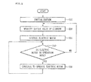
- Fig. 1 is a flowchart showing how a typical electric motor control device applies a DC offset.
- the ECU for operating the electric motor is initialized in step S10 and the current sensor measures a current offset value flowing in each phase in step S20.
- the current offset value is applied so that the operation mode of the ECU for operating the electric motor is executed in step S30.
- the application of PWM namely, the operation state of the electric motor is consistently is checked during the operation of the ECU and when the electric motor is not in the operation state, a pre-measured offset value is re-measured. Also, the electric motor continues to operate according to the driving mode of the ECU irrespective of the change of the offset value in step S50.
- Embodiments provide a device and method for controlling an electric motor that sense an offset of a current applied to an electric motor and perform corresponding compensation.
- a device for controlling an electric motor includes: an inverter supplying a current to an electric motor; a current sensor sensing a current supplied from the inverter to the electric motor; and a control unit enabling the current to be supplied from the inverter to the electric motor, obtaining first and second offset values sensed from the current sensor at a plurality of times, comparing the plurality of offset values obtained, and updating the first offset value to the second offset value according to a result of comparing the offset values.
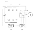
- Fig. 2 is a block diagram of an electric motor control device to which an embodiment is applied.
- an electric motor control device 100 includes an inverter 110, a current sensor 120, a sensing unit 130, and a control unit 140.
- the control unit 140 is connected to a torque sensor (not shown), receives an electrical signal from the torque sensor to check a generated torque and calculates a control current according to the generated torque to control the inverter 110 so that a supply current corresponding to the control current is supplied to an electric motor M by the inverter 110.
- the control unit 140 may store an algorithm that compensates in real time for the DC offsets of an a-phase current sensor 121 and a b-phase current sensor 122 that are attached to a wiring between the inverter 110 and the electric motor M.
- the control unit 140 may use each current sensor 120 to measure an a-phase current value and a b-phase current value, calculate and store the DC offset of each phase based on the current value of each phase, and then update an offset when the current control of the electric motor M is performed.
- the offset is a voltage obtained by subtracting a reference voltage from a voltage that is obtained by multiplying the current value of each phase by the equivalent resistance of the current sensor of each phase.
- control unit 140 may include a memory for storing a reference offset value, a measured offset value and an updated offset value.
- the memory (not shown) may be integrated into or separated from the control unit 140.
- the inverter 110 is a power supply device that changes a direct current to an alternating current to supply power to the electric motor M. It is possible to supply a current to the electric motor M based on the control of the control unit 140. That is, when a control current is received from the control unit 140, the inverter 110 switches a switching element according to a control current to change a current supplied to the electric motor M to control the operation of the electric motor M.
- the current sensor 120 may be attached to at least two of wirings of the inverter.
- the current sensor 120 according to an embodiment includes the a-phase current sensor 121 and the b-phase current sensor 122, for example.
- the current sensor 120 may sense the current value of each phase.
- the sensing unit 130 may sense sensing current values obtained from at least two of a to c phases and output them to the control unit 140.
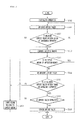
- Fig. 3 is a flowchart of an operation of controlling an electric motor according to an embodiment.
- the control unit 140 of the electric motor control device 100 may perform an initialization operation mode for operating the electric motor in step S302.
- the initialization operation mode may be an initialization state for operating the electric motor or a previous state.
- the sensing unit 130 may obtain offset values from the a-phase current sensor 121 and the b-phase current sensor 122 without performing the current control of the electric motor M in order to measure the current value of each phase based on the control of the control unit 140.
- a current value sensed in a stop state in which the electric motor M does not operate is 'zero', in which case a current sensed at the current sensors 121 and 122 may be an offset value.
- the control unit 140 may determine whether a measured offset value (a first offset value) is within a range of normal offset values (hereinafter, referred to as reference offset values) in step S306. That is, the control unit 140 may fix (a range of) reference offset values for the measured offset value and consider as an offset error when the measured offset value is not within the range of reference offset values in step S308. When the measured offset value is within the range of reference offset values, the control unit 140 may compensate for the measured offset value and perform the control of the electric motor that controls a current applied to the electric motor M in step S310.
- reference offset values a range of normal offset values
- the measured offset value may be stored in the memory (not shown).
- the control unit 140 may consistently check (wait for) the operation state of the electric motor during the operation of the electric motor M and determine whether the electric motor M is in a stop state (a non-operation mode) in step S312.
- the control unit 140 may re-measure an offset value when the electric motor M is in the non-operation mode in step S314.
- the control unit 140 re-measures the offset while the electric motor m is in the non-operation mode, namely, while an applied current is zero.
- the control unit 140 may determine whether a re-measured current value, namely, an offset value (a second offset value) is within a preset range of reference offset values in step S316.
- the control unit 140 may compare it with a previously measured offset value (the current offset value) based on Equation 1 below: Sn - Sc ⁇ V , where Sn is the re-measured offset value, Sc is the previously measured offset value (the current offset value), and V is a reference value of the effectiveness of an offset value.
- the control unit 140 may calculate a difference between the re-measured offset value Sn and the current offset value Sc and determine whether a calculation result is equal to or greater than the reference value of the effectiveness of the offset value in step S316. That is, the control unit 140 may determine that the re-measured offset value Sn is not effective when the re-measured offset value Sn and the current offset value Sc are not within a range of the reference value of the effectiveness. In this case, the current offset value Sc is not updated to the re-measured offset value.
- the control unit 140 may use the current offset value Sc for the control of the electric motor, re-measure offset values a certain number of times and determine the effectiveness when the electric motor is in the non-operation mode. In this case, when it is confirmed a certain number of times or more that the offset values are not effective, it is possible to stop the control of the electric motor (turn off the electric motor) and sound the alarm related to an offset value error.
- any reference in this specification to "one embodiment,” “an embodiment,” “example embodiment,” etc. means that a particular feature, structure, or characteristic described in connection with the embodiment is included in at least one embodiment of the invention.
- the appearances of such phrases in various places in the specification are not necessarily all referring to the same embodiment.
Landscapes
- Engineering & Computer Science (AREA)
- Power Engineering (AREA)
- Control Of Ac Motors In General (AREA)
- Control Of Motors That Do Not Use Commutators (AREA)
- Control Of Electric Motors In General (AREA)
Applications Claiming Priority (1)
| Application Number | Priority Date | Filing Date | Title |
|---|---|---|---|
| KR1020140008994A KR101840084B1 (ko) | 2014-01-24 | 2014-01-24 | 전동기 제어 장치 및 방법 |
Publications (2)
| Publication Number | Publication Date |
|---|---|
| EP2903151A1 true EP2903151A1 (de) | 2015-08-05 |
| EP2903151B1 EP2903151B1 (de) | 2020-05-06 |
Family
ID=52345113
Family Applications (1)
| Application Number | Title | Priority Date | Filing Date |
|---|---|---|---|
| EP15151411.4A Not-in-force EP2903151B1 (de) | 2014-01-24 | 2015-01-16 | Vorrichtung zum Steuern eines Elektromotors |
Country Status (6)
| Country | Link |
|---|---|
| US (1) | US9705444B2 (de) |
| EP (1) | EP2903151B1 (de) |
| JP (1) | JP6027152B2 (de) |
| KR (1) | KR101840084B1 (de) |
| CN (1) | CN104802849A (de) |
| ES (1) | ES2806555T3 (de) |
Families Citing this family (4)
| Publication number | Priority date | Publication date | Assignee | Title |
|---|---|---|---|---|
| FR3060127B1 (fr) | 2016-12-13 | 2019-03-15 | Seb S.A. | Procede de compensation dynamique de l'erreur d'offset d'une chaine d'acquisition comportant un capteur de courant |
| US11703608B2 (en) * | 2020-12-29 | 2023-07-18 | Landmark Graphics Corporation | Reservoir characterization using machine-learning techniques |
| DE102023208427A1 (de) * | 2023-09-01 | 2025-03-06 | Robert Bosch Gesellschaft mit beschränkter Haftung | Verfahren zum Abgleich einer Phasenstrommessanordnung für eine Antriebsanordnung mit mehreren Phasen |
| DE102023208428A1 (de) * | 2023-09-01 | 2025-03-06 | Robert Bosch Gesellschaft mit beschränkter Haftung | Verfahren zum Abgleich einer Phasenstrommessanordnung für eine Antriebsanordnung mit mehreren Phasen |
Citations (3)
| Publication number | Priority date | Publication date | Assignee | Title |
|---|---|---|---|---|
| DE3942167A1 (de) * | 1988-12-21 | 1990-06-28 | Fuji Heavy Ind Ltd | Fehlererfassungseinrichtung fuer elektrische schaltungen |
| JP2012182920A (ja) * | 2011-03-02 | 2012-09-20 | Nissan Motor Co Ltd | 電流センサ制御装置 |
| EP2607914A1 (de) * | 2011-12-19 | 2013-06-26 | LSIS Co., Ltd. | Vorrichtung und Verfahren zum Ausgleichen des Versatzes eines Stromsensors |
Family Cites Families (8)
| Publication number | Priority date | Publication date | Assignee | Title |
|---|---|---|---|---|
| JPS6023268A (ja) | 1983-07-18 | 1985-02-05 | 三菱電機株式会社 | エレベ−タの速度制御装置 |
| JP3236449B2 (ja) | 1994-08-04 | 2001-12-10 | ファナック株式会社 | Acサーボモータの制御方法 |
| JP3663880B2 (ja) | 1998-02-03 | 2005-06-22 | 日本精工株式会社 | 電動パワーステアリング装置の制御装置 |
| JP2001186784A (ja) * | 1999-12-27 | 2001-07-06 | Yaskawa Electric Corp | トルクリップル低減装置 |
| JP5018850B2 (ja) * | 2009-09-28 | 2012-09-05 | 三菱電機株式会社 | 電動機制御装置 |
| JP5613537B2 (ja) * | 2010-11-18 | 2014-10-22 | カヤバ工業株式会社 | 電動パワーステアリング装置の調整装置及び調整方法 |
| JP2013017363A (ja) | 2011-07-06 | 2013-01-24 | Omron Automotive Electronics Co Ltd | モータ制御装置 |
| JP5880967B2 (ja) * | 2012-09-28 | 2016-03-09 | 株式会社デンソー | 交流電動機の制御装置 |
-
2014
- 2014-01-24 KR KR1020140008994A patent/KR101840084B1/ko active Active
-
2015
- 2015-01-14 US US14/597,078 patent/US9705444B2/en active Active
- 2015-01-16 ES ES15151411T patent/ES2806555T3/es active Active
- 2015-01-16 EP EP15151411.4A patent/EP2903151B1/de not_active Not-in-force
- 2015-01-23 CN CN201510081801.XA patent/CN104802849A/zh active Pending
- 2015-01-23 JP JP2015011282A patent/JP6027152B2/ja not_active Expired - Fee Related
Patent Citations (3)
| Publication number | Priority date | Publication date | Assignee | Title |
|---|---|---|---|---|
| DE3942167A1 (de) * | 1988-12-21 | 1990-06-28 | Fuji Heavy Ind Ltd | Fehlererfassungseinrichtung fuer elektrische schaltungen |
| JP2012182920A (ja) * | 2011-03-02 | 2012-09-20 | Nissan Motor Co Ltd | 電流センサ制御装置 |
| EP2607914A1 (de) * | 2011-12-19 | 2013-06-26 | LSIS Co., Ltd. | Vorrichtung und Verfahren zum Ausgleichen des Versatzes eines Stromsensors |
Also Published As
| Publication number | Publication date |
|---|---|
| US20150214881A1 (en) | 2015-07-30 |
| JP6027152B2 (ja) | 2016-11-16 |
| US9705444B2 (en) | 2017-07-11 |
| ES2806555T3 (es) | 2021-02-18 |
| JP2015139368A (ja) | 2015-07-30 |
| EP2903151B1 (de) | 2020-05-06 |
| KR101840084B1 (ko) | 2018-03-19 |
| CN104802849A (zh) | 2015-07-29 |
| KR20150088541A (ko) | 2015-08-03 |
Similar Documents
| Publication | Publication Date | Title |
|---|---|---|
| JP6298390B2 (ja) | 電動機駆動制御装置、電動パワーステアリング装置、電動ブレーキ装置、電動ポンプ装置 | |
| US9787240B2 (en) | Controller and control method for motor | |
| EP2518894B1 (de) | Motorsteuereinheit und Fahrzeuglenksystem | |
| CN108134558B (zh) | 电动机系统的控制装置及温度检测状态判定方法 | |
| CN105007019B (zh) | 逆变器装置 | |
| JP5428325B2 (ja) | モータ制御装置および電動パワーステアリング装置 | |
| WO2009087991A1 (ja) | モータ制御装置および電動パワーステアリング装置 | |
| CN107453683B (zh) | 用于控制或管理dc电机的方法和系统 | |
| KR20120029084A (ko) | 전동식 파워 스티어링 장치 | |
| EP2903151A1 (de) | Vorrichtung und Verfahren zum Steuern eines Elektromotors | |
| CN103929111A (zh) | 电动机控制装置和电动助力转向设备 | |
| JP2014168341A (ja) | モータ制御装置 | |
| CN106063112A (zh) | 动力转向装置以及动力转向装置用控制装置 | |
| JP5440120B2 (ja) | モータ制御装置および電動パワーステアリング装置 | |
| JP2009232569A (ja) | モータ駆動制御装置及びこれを使用した電動パワーステアリング装置 | |
| JP6459229B2 (ja) | 電動パワーステアリング装置 | |
| JP4794603B2 (ja) | ブラシレスモータ制御装置 | |
| JP2014168340A (ja) | モータ制御装置 | |
| KR20130109766A (ko) | 모터 모델링을 이용한 eps 모터의 오픈루프 토크 제어 장치 및 방법 | |
| EP2594459B1 (de) | Motorsteuereinheit und elektrisches Fahrzeug-Servolenkungssystem | |
| KR20160135498A (ko) | 전류센서 이득보상방법 및 그를 위한 전자제어장치 | |
| KR101348569B1 (ko) | 전동 파워스티어링 장치 및 그의 과열방지방법 | |
| JP5444697B2 (ja) | モータ制御装置および電動パワーステアリング装置 | |
| JP5975143B2 (ja) | 車両用操舵装置 | |
| KR20020053925A (ko) | 모터 코일을 이용한 온도 측정방법 |
Legal Events
| Date | Code | Title | Description |
|---|---|---|---|
| PUAI | Public reference made under article 153(3) epc to a published international application that has entered the european phase |
Free format text: ORIGINAL CODE: 0009012 |
|
| 17P | Request for examination filed |
Effective date: 20150116 |
|
| AK | Designated contracting states |
Kind code of ref document: A1 Designated state(s): AL AT BE BG CH CY CZ DE DK EE ES FI FR GB GR HR HU IE IS IT LI LT LU LV MC MK MT NL NO PL PT RO RS SE SI SK SM TR |
|
| AX | Request for extension of the european patent |
Extension state: BA ME |
|
| 17P | Request for examination filed |
Effective date: 20160204 |
|
| RBV | Designated contracting states (corrected) |
Designated state(s): AL AT BE BG CH CY CZ DE DK EE ES FI FR GB GR HR HU IE IS IT LI LT LU LV MC MK MT NL NO PL PT RO RS SE SI SK SM TR |
|
| GRAP | Despatch of communication of intention to grant a patent |
Free format text: ORIGINAL CODE: EPIDOSNIGR1 |
|
| STAA | Information on the status of an ep patent application or granted ep patent |
Free format text: STATUS: GRANT OF PATENT IS INTENDED |
|
| RIC1 | Information provided on ipc code assigned before grant |
Ipc: G01R 15/14 20060101ALI20200206BHEP Ipc: H02P 6/10 20060101AFI20200206BHEP Ipc: H02P 7/00 20160101ALN20200206BHEP Ipc: H02P 31/00 20060101ALI20200206BHEP Ipc: H02P 21/22 20160101ALI20200206BHEP |
|
| INTG | Intention to grant announced |
Effective date: 20200227 |
|
| GRAS | Grant fee paid |
Free format text: ORIGINAL CODE: EPIDOSNIGR3 |
|
| GRAA | (expected) grant |
Free format text: ORIGINAL CODE: 0009210 |
|
| STAA | Information on the status of an ep patent application or granted ep patent |
Free format text: STATUS: THE PATENT HAS BEEN GRANTED |
|
| AK | Designated contracting states |
Kind code of ref document: B1 Designated state(s): AL AT BE BG CH CY CZ DE DK EE ES FI FR GB GR HR HU IE IS IT LI LT LU LV MC MK MT NL NO PL PT RO RS SE SI SK SM TR |
|
| REG | Reference to a national code |
Ref country code: GB Ref legal event code: FG4D |
|
| REG | Reference to a national code |
Ref country code: AT Ref legal event code: REF Ref document number: 1268443 Country of ref document: AT Kind code of ref document: T Effective date: 20200515 Ref country code: CH Ref legal event code: EP |
|
| REG | Reference to a national code |
Ref country code: IE Ref legal event code: FG4D |
|
| REG | Reference to a national code |
Ref country code: DE Ref legal event code: R096 Ref document number: 602015051974 Country of ref document: DE |
|
| REG | Reference to a national code |
Ref country code: LT Ref legal event code: MG4D |
|
| REG | Reference to a national code |
Ref country code: NL Ref legal event code: MP Effective date: 20200506 |
|
| PG25 | Lapsed in a contracting state [announced via postgrant information from national office to epo] |
Ref country code: LT Free format text: LAPSE BECAUSE OF FAILURE TO SUBMIT A TRANSLATION OF THE DESCRIPTION OR TO PAY THE FEE WITHIN THE PRESCRIBED TIME-LIMIT Effective date: 20200506 Ref country code: SE Free format text: LAPSE BECAUSE OF FAILURE TO SUBMIT A TRANSLATION OF THE DESCRIPTION OR TO PAY THE FEE WITHIN THE PRESCRIBED TIME-LIMIT Effective date: 20200506 Ref country code: GR Free format text: LAPSE BECAUSE OF FAILURE TO SUBMIT A TRANSLATION OF THE DESCRIPTION OR TO PAY THE FEE WITHIN THE PRESCRIBED TIME-LIMIT Effective date: 20200807 Ref country code: NO Free format text: LAPSE BECAUSE OF FAILURE TO SUBMIT A TRANSLATION OF THE DESCRIPTION OR TO PAY THE FEE WITHIN THE PRESCRIBED TIME-LIMIT Effective date: 20200806 Ref country code: FI Free format text: LAPSE BECAUSE OF FAILURE TO SUBMIT A TRANSLATION OF THE DESCRIPTION OR TO PAY THE FEE WITHIN THE PRESCRIBED TIME-LIMIT Effective date: 20200506 Ref country code: PT Free format text: LAPSE BECAUSE OF FAILURE TO SUBMIT A TRANSLATION OF THE DESCRIPTION OR TO PAY THE FEE WITHIN THE PRESCRIBED TIME-LIMIT Effective date: 20200907 Ref country code: IS Free format text: LAPSE BECAUSE OF FAILURE TO SUBMIT A TRANSLATION OF THE DESCRIPTION OR TO PAY THE FEE WITHIN THE PRESCRIBED TIME-LIMIT Effective date: 20200906 |
|
| PG25 | Lapsed in a contracting state [announced via postgrant information from national office to epo] |
Ref country code: RS Free format text: LAPSE BECAUSE OF FAILURE TO SUBMIT A TRANSLATION OF THE DESCRIPTION OR TO PAY THE FEE WITHIN THE PRESCRIBED TIME-LIMIT Effective date: 20200506 Ref country code: LV Free format text: LAPSE BECAUSE OF FAILURE TO SUBMIT A TRANSLATION OF THE DESCRIPTION OR TO PAY THE FEE WITHIN THE PRESCRIBED TIME-LIMIT Effective date: 20200506 Ref country code: HR Free format text: LAPSE BECAUSE OF FAILURE TO SUBMIT A TRANSLATION OF THE DESCRIPTION OR TO PAY THE FEE WITHIN THE PRESCRIBED TIME-LIMIT Effective date: 20200506 Ref country code: BG Free format text: LAPSE BECAUSE OF FAILURE TO SUBMIT A TRANSLATION OF THE DESCRIPTION OR TO PAY THE FEE WITHIN THE PRESCRIBED TIME-LIMIT Effective date: 20200806 |
|
| REG | Reference to a national code |
Ref country code: AT Ref legal event code: MK05 Ref document number: 1268443 Country of ref document: AT Kind code of ref document: T Effective date: 20200506 |
|
| PG25 | Lapsed in a contracting state [announced via postgrant information from national office to epo] |
Ref country code: NL Free format text: LAPSE BECAUSE OF FAILURE TO SUBMIT A TRANSLATION OF THE DESCRIPTION OR TO PAY THE FEE WITHIN THE PRESCRIBED TIME-LIMIT Effective date: 20200506 Ref country code: AL Free format text: LAPSE BECAUSE OF FAILURE TO SUBMIT A TRANSLATION OF THE DESCRIPTION OR TO PAY THE FEE WITHIN THE PRESCRIBED TIME-LIMIT Effective date: 20200506 |
|
| PG25 | Lapsed in a contracting state [announced via postgrant information from national office to epo] |
Ref country code: EE Free format text: LAPSE BECAUSE OF FAILURE TO SUBMIT A TRANSLATION OF THE DESCRIPTION OR TO PAY THE FEE WITHIN THE PRESCRIBED TIME-LIMIT Effective date: 20200506 Ref country code: SM Free format text: LAPSE BECAUSE OF FAILURE TO SUBMIT A TRANSLATION OF THE DESCRIPTION OR TO PAY THE FEE WITHIN THE PRESCRIBED TIME-LIMIT Effective date: 20200506 Ref country code: RO Free format text: LAPSE BECAUSE OF FAILURE TO SUBMIT A TRANSLATION OF THE DESCRIPTION OR TO PAY THE FEE WITHIN THE PRESCRIBED TIME-LIMIT Effective date: 20200506 Ref country code: CZ Free format text: LAPSE BECAUSE OF FAILURE TO SUBMIT A TRANSLATION OF THE DESCRIPTION OR TO PAY THE FEE WITHIN THE PRESCRIBED TIME-LIMIT Effective date: 20200506 Ref country code: DK Free format text: LAPSE BECAUSE OF FAILURE TO SUBMIT A TRANSLATION OF THE DESCRIPTION OR TO PAY THE FEE WITHIN THE PRESCRIBED TIME-LIMIT Effective date: 20200506 Ref country code: AT Free format text: LAPSE BECAUSE OF FAILURE TO SUBMIT A TRANSLATION OF THE DESCRIPTION OR TO PAY THE FEE WITHIN THE PRESCRIBED TIME-LIMIT Effective date: 20200506 |
|
| REG | Reference to a national code |
Ref country code: DE Ref legal event code: R097 Ref document number: 602015051974 Country of ref document: DE |
|
| REG | Reference to a national code |
Ref country code: ES Ref legal event code: FG2A Ref document number: 2806555 Country of ref document: ES Kind code of ref document: T3 Effective date: 20210218 |
|
| PG25 | Lapsed in a contracting state [announced via postgrant information from national office to epo] |
Ref country code: PL Free format text: LAPSE BECAUSE OF FAILURE TO SUBMIT A TRANSLATION OF THE DESCRIPTION OR TO PAY THE FEE WITHIN THE PRESCRIBED TIME-LIMIT Effective date: 20200506 Ref country code: SK Free format text: LAPSE BECAUSE OF FAILURE TO SUBMIT A TRANSLATION OF THE DESCRIPTION OR TO PAY THE FEE WITHIN THE PRESCRIBED TIME-LIMIT Effective date: 20200506 |
|
| PLBE | No opposition filed within time limit |
Free format text: ORIGINAL CODE: 0009261 |
|
| STAA | Information on the status of an ep patent application or granted ep patent |
Free format text: STATUS: NO OPPOSITION FILED WITHIN TIME LIMIT |
|
| 26N | No opposition filed |
Effective date: 20210209 |
|
| PG25 | Lapsed in a contracting state [announced via postgrant information from national office to epo] |
Ref country code: SI Free format text: LAPSE BECAUSE OF FAILURE TO SUBMIT A TRANSLATION OF THE DESCRIPTION OR TO PAY THE FEE WITHIN THE PRESCRIBED TIME-LIMIT Effective date: 20200506 |
|
| PG25 | Lapsed in a contracting state [announced via postgrant information from national office to epo] |
Ref country code: MC Free format text: LAPSE BECAUSE OF FAILURE TO SUBMIT A TRANSLATION OF THE DESCRIPTION OR TO PAY THE FEE WITHIN THE PRESCRIBED TIME-LIMIT Effective date: 20200506 |
|
| REG | Reference to a national code |
Ref country code: CH Ref legal event code: PL |
|
| PG25 | Lapsed in a contracting state [announced via postgrant information from national office to epo] |
Ref country code: LU Free format text: LAPSE BECAUSE OF NON-PAYMENT OF DUE FEES Effective date: 20210116 |
|
| REG | Reference to a national code |
Ref country code: BE Ref legal event code: MM Effective date: 20210131 |
|
| PG25 | Lapsed in a contracting state [announced via postgrant information from national office to epo] |
Ref country code: CH Free format text: LAPSE BECAUSE OF NON-PAYMENT OF DUE FEES Effective date: 20210131 Ref country code: LI Free format text: LAPSE BECAUSE OF NON-PAYMENT OF DUE FEES Effective date: 20210131 |
|
| PG25 | Lapsed in a contracting state [announced via postgrant information from national office to epo] |
Ref country code: IE Free format text: LAPSE BECAUSE OF NON-PAYMENT OF DUE FEES Effective date: 20210116 |
|
| PG25 | Lapsed in a contracting state [announced via postgrant information from national office to epo] |
Ref country code: BE Free format text: LAPSE BECAUSE OF NON-PAYMENT OF DUE FEES Effective date: 20210131 |
|
| PGFP | Annual fee paid to national office [announced via postgrant information from national office to epo] |
Ref country code: FR Payment date: 20230105 Year of fee payment: 9 Ref country code: ES Payment date: 20230222 Year of fee payment: 9 |
|
| PG25 | Lapsed in a contracting state [announced via postgrant information from national office to epo] |
Ref country code: HU Free format text: LAPSE BECAUSE OF FAILURE TO SUBMIT A TRANSLATION OF THE DESCRIPTION OR TO PAY THE FEE WITHIN THE PRESCRIBED TIME-LIMIT; INVALID AB INITIO Effective date: 20150116 |
|
| PGFP | Annual fee paid to national office [announced via postgrant information from national office to epo] |
Ref country code: IT Payment date: 20230109 Year of fee payment: 9 Ref country code: GB Payment date: 20230105 Year of fee payment: 9 Ref country code: DE Payment date: 20230105 Year of fee payment: 9 |
|
| PG25 | Lapsed in a contracting state [announced via postgrant information from national office to epo] |
Ref country code: CY Free format text: LAPSE BECAUSE OF FAILURE TO SUBMIT A TRANSLATION OF THE DESCRIPTION OR TO PAY THE FEE WITHIN THE PRESCRIBED TIME-LIMIT Effective date: 20200506 |
|
| P01 | Opt-out of the competence of the unified patent court (upc) registered |
Effective date: 20230625 |
|
| PG25 | Lapsed in a contracting state [announced via postgrant information from national office to epo] |
Ref country code: MK Free format text: LAPSE BECAUSE OF FAILURE TO SUBMIT A TRANSLATION OF THE DESCRIPTION OR TO PAY THE FEE WITHIN THE PRESCRIBED TIME-LIMIT Effective date: 20200506 |
|
| PG25 | Lapsed in a contracting state [announced via postgrant information from national office to epo] |
Ref country code: TR Free format text: LAPSE BECAUSE OF FAILURE TO SUBMIT A TRANSLATION OF THE DESCRIPTION OR TO PAY THE FEE WITHIN THE PRESCRIBED TIME-LIMIT Effective date: 20200506 |
|
| REG | Reference to a national code |
Ref country code: DE Ref legal event code: R119 Ref document number: 602015051974 Country of ref document: DE |
|
| GBPC | Gb: european patent ceased through non-payment of renewal fee |
Effective date: 20240116 |
|
| PG25 | Lapsed in a contracting state [announced via postgrant information from national office to epo] |
Ref country code: MT Free format text: LAPSE BECAUSE OF FAILURE TO SUBMIT A TRANSLATION OF THE DESCRIPTION OR TO PAY THE FEE WITHIN THE PRESCRIBED TIME-LIMIT Effective date: 20200506 |
|
| PG25 | Lapsed in a contracting state [announced via postgrant information from national office to epo] |
Ref country code: DE Free format text: LAPSE BECAUSE OF NON-PAYMENT OF DUE FEES Effective date: 20240801 |
|
| PG25 | Lapsed in a contracting state [announced via postgrant information from national office to epo] |
Ref country code: GB Free format text: LAPSE BECAUSE OF NON-PAYMENT OF DUE FEES Effective date: 20240116 |
|
| PG25 | Lapsed in a contracting state [announced via postgrant information from national office to epo] |
Ref country code: FR Free format text: LAPSE BECAUSE OF NON-PAYMENT OF DUE FEES Effective date: 20240131 |
|
| PG25 | Lapsed in a contracting state [announced via postgrant information from national office to epo] |
Ref country code: GB Free format text: LAPSE BECAUSE OF NON-PAYMENT OF DUE FEES Effective date: 20240116 Ref country code: FR Free format text: LAPSE BECAUSE OF NON-PAYMENT OF DUE FEES Effective date: 20240131 Ref country code: DE Free format text: LAPSE BECAUSE OF NON-PAYMENT OF DUE FEES Effective date: 20240801 |
|
| PG25 | Lapsed in a contracting state [announced via postgrant information from national office to epo] |
Ref country code: IT Free format text: LAPSE BECAUSE OF NON-PAYMENT OF DUE FEES Effective date: 20240116 |
|
| REG | Reference to a national code |
Ref country code: ES Ref legal event code: FD2A Effective date: 20250303 |
|
| PG25 | Lapsed in a contracting state [announced via postgrant information from national office to epo] |
Ref country code: ES Free format text: LAPSE BECAUSE OF NON-PAYMENT OF DUE FEES Effective date: 20240117 |