EP2902637A2 - Vakuumpumpe - Google Patents
Vakuumpumpe Download PDFInfo
- Publication number
- EP2902637A2 EP2902637A2 EP15150410.7A EP15150410A EP2902637A2 EP 2902637 A2 EP2902637 A2 EP 2902637A2 EP 15150410 A EP15150410 A EP 15150410A EP 2902637 A2 EP2902637 A2 EP 2902637A2
- Authority
- EP
- European Patent Office
- Prior art keywords
- vacuum pump
- inlet
- inlets
- pump according
- chamber
- Prior art date
- Legal status (The legal status is an assumption and is not a legal conclusion. Google has not performed a legal analysis and makes no representation as to the accuracy of the status listed.)
- Granted
Links
Images



Classifications
-
- F—MECHANICAL ENGINEERING; LIGHTING; HEATING; WEAPONS; BLASTING
- F04—POSITIVE - DISPLACEMENT MACHINES FOR LIQUIDS; PUMPS FOR LIQUIDS OR ELASTIC FLUIDS
- F04D—NON-POSITIVE-DISPLACEMENT PUMPS
- F04D19/00—Axial-flow pumps
- F04D19/02—Multi-stage pumps
- F04D19/04—Multi-stage pumps specially adapted to the production of a high vacuum, e.g. molecular pumps
- F04D19/044—Holweck-type pumps
-
- F—MECHANICAL ENGINEERING; LIGHTING; HEATING; WEAPONS; BLASTING
- F04—POSITIVE - DISPLACEMENT MACHINES FOR LIQUIDS; PUMPS FOR LIQUIDS OR ELASTIC FLUIDS
- F04D—NON-POSITIVE-DISPLACEMENT PUMPS
- F04D29/00—Details, component parts, or accessories
- F04D29/70—Suction grids; Strainers; Dust separation; Cleaning
- F04D29/701—Suction grids; Strainers; Dust separation; Cleaning especially adapted for elastic fluid pumps
Definitions
- the invention relates to a vacuum pump with at least one Holweckpump process with at least one Holweckstator and at least one Holweckrotor.
- the prior art ( EP 1 668 255 B1 ) includes a vacuum pump, which has two turbomolecular pumping stages and a Holweckpumpcut and is used for the evacuation of chambers of a mass spectrometer.
- an inlet is provided in front of the Holweckstator from a chamber to be evacuated and the incoming gas is passed completely through the Holweckpumpch.
- the technical problem underlying the invention is to pump the gas load, but with reduced power consumption.
- the vacuum pump according to the invention with at least one Holweckpump process with at least one Holweckstator and at least one Holweckrotor is characterized in that at least one gas inlet is provided in the Holweckstator the at least one Holweckpumpcut.
- This embodiment of a vacuum pump according to the invention has the advantage that the Holweck stage, which has an axial length, makes it possible to distribute one or more taps (Interstage ports) in axial length.
- This has the advantage that the high gas load of the corresponding chamber, which is associated with the inlet, does not flow completely through a tapping of the Holweck stage, but divides itself, so that a part of the gas stream takes a shorter path through the Holweck stage. This reduces the gas friction and especially the power consumption and the temperature.
- At least two inlets are provided in the tangential direction of the Holweckstators.
- At least one gas inlet is provided in the axial direction of the Holweckstators.
- the gas inlets in the axial direction which are arranged at one and the same pressure level, but can be distributed over several inlets, which are advantageously arranged tangentially symmetrical in Holweckstator. However, they can also be arranged asymmetrically with respect to the radial circumference.
- the at least one inlet may be formed as a bore and / or slot and / or slot. These embodiments can be adapted to customer-specific requirements. This makes any geometry possible.
- a further embodiment of the invention provides that the inlets have the same or different cross sections.
- the inlets have different cross sections, as a result, an optimized pumping action can be adjusted.
- the openings of the inlets are advantageously larger than the openings in the fore-vacuum area.
- each inlet is connected to only one chamber to be evacuated.
- the arrangement of at least one inlet in the region of the Holweckstators has the advantage that in addition to the inlets further compression stages are present, which, as already stated, has a positive effect on the gas friction and the power consumption and temperature.
- At least one additional turbomolecular pump stage is advantageously provided.
- At least two inlets are arranged in the Holweckstator and the inlet, which is arranged in the axial direction of the vacuum pump closer to the turbomolecular pumping stage, is designed as an inlet arranged in the region of molecular flow.
- At least two inlets are arranged in the Holweckstator and the inlet, which is arranged in the axial direction of the vacuum pump further away from the turbomolecular pumping stage, is advantageously designed as an arranged in the region of the Knudsen flow inlet.
- Knudsen flow The transition from the viscous flow to the molecular flow is called Knudsen flow.
- the Knudsen flow prevails in the fine vacuum range from 0.1 Pascal to 100 Pascal.
- Knudsen number between 0.01 and 0.5 one speaks of Knudsen flow. Since many process pressures are in the fine vacuum range, this type of flow is correspondingly frequently represented in technical vacuum applications.
- the molecular flow prevails in contrast to the viscous flow, when the mean free path of the gas particles is significantly larger than the diameter of the flow, that is, when the Knudsen number is significantly greater than 1.
- the molecular flow is predominant in the high vacuum range ( 10 -3 to 10 -7 hPa) and ultrahigh vacuum range (smaller 10 -7 hPa).
- K n I ⁇ d ,
- the inlets are tapered in the direction of the Holweckrotors.
- the Holweckstator on channels and the at least one inlet is arranged in the region of a channel bottom.
- the pump-active structure of the Holweckstators is maintained, although an inlet is provided in the region of Holweckstators.
- the at least one inlet is arranged exclusively in a channel bottom. This ensures that the channels of the Holweckstators are not changed and thereby an optimal pumping action is achieved.
- a further advantageous embodiment of the invention provides that all inlets are arranged in the region of a channel bottom.
- a vacuum pump 1 and a chamber system 2 is shown in a chamber housing 2, a fore-vacuum chamber 4 and a high-vacuum chamber 12 are provided, which are connected to one another via a high-vacuum diaphragm 22.
- a particle beam can enter the pre-vacuum chamber 4 through a pre-vacuum diaphragm 14.
- a pump housing 40 of the vacuum pump 1 is vacuum-tight and releasably connected.
- a shaft 42 is arranged, which of a high-vacuum-side bearing 44 and a fore-vacuum side bearing 48 is rotatably supported.
- the storage can be realized, for example, by two bearings, furthermore, the vorvakuum possiblye bearing can be designed as a rolling bearing and the high-vacuum side bearing as a permanent magnet bearing. Even a fully magnetic storage is possible.
- a permanent magnet 52 is provided which cooperates with the magnetic field of a drive coil 50 and thus the shaft 42 is set in rapid rotation.
- fast means that the pump-active components develop a pumping effect due to molecular mechanisms and the rotational speed is at some 10,000 revolutions per minute.
- the vacuum pump 1 has a first inlet 80 and a second inlet 82.
- the first inlet 80 is connected to the fore-vacuum chamber 4, while the second inlet 82 is connected to the high-vacuum chamber 12.
- the gas entering the vacuum pump 1 through the first inlet 80 passes into a pumping stage 70, as does the second inlet 82.
- This pumping stage 70 is formed as a Holweckpump process with a Holweckstator 74 and a Holweckzylinder 72.
- the Holweckstator 74 essentially has a thick-walled hollow cylinder with thread-like, running on its inside channels 76 with a square cross section. Within this cylinder, a ring nut 72 connected to the shaft 42 runs.
- the ring nut cylinder 72 may be made of a compound material such as carbon fiber reinforced plastic (CFRP), but may also be made of a metal, ideally an aluminum alloy. This at least partially surrounds the high-vacuum side bearing 44 and a bearing support 46 which fixes this bearing 44 on the pump housing 10.
- CFRP carbon fiber reinforced plastic
- a further pumping stage 60 is provided in the vacuum pump 1.
- the pumping stage 60 is designed as a turbomolecular pumping stage and therefore has respective rotor disks 62 and stator disks 64 provided with a blade ring. These are axially spaced by spacers 66.
- the pumping stage 60 may comprise a plurality of rotor and stator disks, depending on the required pressure ratio between the suction region and the discharge region of the pumping stage. The gas is transferred from the pumping stage 60 to an outlet 54 of the vacuum pump 1 and leaves through this the vacuum pump 1.
- turbo disks 62 may be individually fitted to the shaft 42, but one-piece turbo disks (bell rotors) are also possible.
- the fore-vacuum chamber 4 is evacuated.
- the high vacuum chamber 12 is evacuated.
- the inlets 80 and 82 are at different pressure levels of the Holweckpumphand 70.
- the pressure level of the high vacuum chamber 12 is below the pressure level of the Vorvakuumhunt. 4
- the gas ejected from the pumping stage 70 is conveyed further by the pumping stage 60 in the direction of the outlet 54.
- the arrangement of the inlets 80 and 82 in the region of Holweckstators 74 ensures that the high gas load of the chamber 4 does not flow completely through the Holweckpumpmeasure 70, but only through a part, so that the gas flow flowing through the inlet 80, a takes a shorter path through the Holweckcut. This reduces the gas friction and especially the power consumption and the temperature.
- Fig. 2 shows the vacuum pump 1 with a chamber housing 2. Parts with Fig. 1 match, are provided with the same reference numbers.
- the chamber housing 2 three chambers 5, 6, 7 are arranged. Between the chambers 5, 6, a diaphragm 3 and between the chambers 6, 7, a diaphragm 8 is arranged. In the aperture 3 and in the aperture 8 openings are provided, so that in the direction of arrows A, B, the gas can enter the adjacent chambers.
- the Holweckpumptreatment 70 with the Holweckstator 74 has two inlets 11, 13, through which the gas from the chamber 6 in the direction of arrows C, D can get into the Holweckpumptreatment 70.
- These multiple inlets 11, 13 have the advantage that they are distributed in the axial length of the vacuum pumping stage 70. This has the advantage that the high gas load of the corresponding chamber 6 does not flow completely through an inlet 11 of the Holweckhand 70, but divides, so that a portion of the gas stream takes a shorter path through the Holweckcut69. This reduces the gas friction and especially the power consumption and the temperature.
- a further outlet 9 is provided, so that the chamber 7 is evacuated by the turbomolecular pumping stage 60.
- a particle beam can enter the vacuum chamber 5.
- the gas exiting the chamber 6 into the Holweckpumptreatment 70 is provided by the Holweckpumptreatment 70, consisting from Holweckstator 74 and Holweckrotor 72, promoted toward the turbomolecular pumping stage 60 and discharged via an outlet 54.
- Fig. 3 shows the vacuum pump 1 with a chamber system 2. The same parts are provided with the same reference numbers.
- an additional aperture 15 is arranged, so that about 80% of the gas from the chamber 6 are evacuated through the inlet 11 in the region of the Holweckstators 74 and about the inlet 13 about 20%.
- the inlet 11 has a larger cross-section than the inlet 13. This means that the inlet, which is arranged closer to the turbomolecular pumping stage 60 in the axial direction, has a smaller cross-section than the inlet, which is arranged farther away from the turbomolecular pumping stage 60 ,
- the Holweckstator 74 channels 76.
- the inlet 11 is arranged in the region of a channel 76 in order not to substantially change the structure of the Holweckstators 74 and thereby achieve an optimized pumping action.
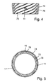
- Fig. 5 shows the Holweckstator 74 with the channels 76.
- Radially symmetrically distributed inlets 11, 16, 17 in the Holweckstator 74 are arranged. These inlets 11, 16, 17 are seen in the axial direction of Holweckstators 74 at a pressure level, that is arranged lying at the same height.
- the inlet 16 is designed to taper in the direction of the hollow rotor 72, for example, but the inlets may also be cylindrical in cross-section, like the inlet 11.
- Conceivable cooling is here a convection cooling, a forced air cooling by means of a fan or a water cooling.
- Fig. 6 shows a chamber 12 in which a gas load Q of 5 mbar l / s (liters per second) flows.
- the chamber 12 has a tap 82 to a Holweckcut 72, 74.
- the single tap 82 has an inverse flow resistance, or conductance L of 4 l / s.
- the pumping direction runs in the direction of arrow E.
- Fig. 7 an embodiment of the invention with two outlets 80, 82 is shown.
- the chamber 12 flows a gas load Q of 5 mbar l / s.
- the chamber 12 has the two taps 80, 82 to the Holweckcut 72, 74.
- the upper tap 82 has an inverse flow resistance or conductance L 1 of 4 l / s.
- S 0-1 In the pumping Holweckcut 72, 74 there is a nominal pumping speed S 0-1 of 10 l / s at the axial height of the upper tap.
- S eff- 1 of 2.86 1 / s at the upper tap 82 of the chamber 12.
- the lower tap 80 has an inverse flow resistance or conductance L 2 of 4 l / s.
- L 2 inverse flow resistance or conductance
- 74 there is a nominal pumping speed S 0-1 of 5 1 / s at the axial height of the lower tap.
Landscapes
- Engineering & Computer Science (AREA)
- Mechanical Engineering (AREA)
- General Engineering & Computer Science (AREA)
- Non-Positive Displacement Air Blowers (AREA)
- Reciprocating Pumps (AREA)
Abstract
Description
- Die Erfindung betrifft eine Vakuumpumpe mit wenigstens einer Holweckpumpstufe mit wenigstens einem Holweckstator und wenigstens einem Holweckrotor.
- Zum Stand der Technik (
EP 1 668 255 B1 ) gehört eine Vakuumpumpe, die zwei Turbomolekularpumpstufen und eine Holweckpumpstufe aufweist und zur Evakuierung von Kammern eines Massenspektrometers eingesetzt wird. - Bei dieser zum Stand der Technik gehörenden Vakuumpumpe ist vor dem Holweckstator ein Einlass aus einer zu evakuierenden Kammer vorgesehen und das einströmende Gas wird vollständig durch die Holweckpumpstufe geleitet.
- Diese zum Stand der Technik gehörende Vakuumpumpe weist den Nachteil auf, dass die hohe Gaslast einen hohen Druck erzeugt, der durch Gasreibung bedingt zu einer sehr hohen Leistungsaufnahme und hohen Temperaturen führt.
- Das der Erfindung zugrundeliegende technische Problem besteht darin, die Gaslast zu pumpen, jedoch mit reduzierter Leistungsaufnahme.
- Dieses technische Problem wird durch eine Vakuumpumpe mit den Merkmalen gemäß Anspruch 1 gelöst.
- Die erfindungsgemäße Vakuumpumpe mit wenigstens einer Holweckpumpstufe mit wenigstens einem Holweckstator und wenigstens einem Holweckrotor zeichnet sich dadurch aus, dass in dem Holweckstator der wenigstens einen Holweckpumpstufe wenigstens ein Gaseinlass vorgesehen ist.
- Diese erfindungsgemäße Ausführung einer Vakuumpumpe weist den Vorteil auf, dass die Holweckstufe, die eine axiale Baulänge aufweist, es ermöglicht, einen oder mehrere Anzapfungen (Interstageports) in axialer Länge zu verteilen. Dies hat den Vorteil, dass die hohe Gaslast der entsprechenden Kammer, die dem Einlass zugeordnet ist, nicht komplett durch eine Anzapfung der Holweckstufe strömt, sondern sich aufteilt, so dass ein Teil des Gasstromes einen kürzeren Weg durch die Holweckstufe nimmt. Hierdurch reduziert sich die Gasreibung und besonders die Leistungsaufnahme und die Temperatur.
- Es ist vorteilhaft, wenigstens einen Gaseinlass in dem Holweckstator vorzusehen. Hierdurch wird schon erreicht, dass die hohe Gaslast nicht komplett durch die gesamte Holweckstufe strömt.
- Vorteilhaft ist es, wenigstens zwei Einlässe in axialer Richtung des Holweckstators vorzusehen, da hierdurch eine bessere Aufteilung erzielt werden kann.
- Gemäß einer weiteren vorteilhaften Ausführungsform der Erfindung sind in tangentialer Richtung des Holweckstators wenigstens zwei Einlässe vorgesehen.
- Das bedeutet, dass in axialer Richtung des Holweckstators wenigstens ein Gaseinlass vorgesehen ist. Die Gaseinlässe in axialer Richtung, die auf ein und demselben Druckniveau angeordnet sind, können sich jedoch auf mehrere Einlässe verteilen, die vorteilhaft tangentialsymmetrisch im Holweckstator angeordnet sind. Sie können jedoch auch asymmetrisch, bezogen auf den radialen Umfang angeordnet sein.
- Der wenigstens eine Einlass kann als Bohrung und/oder Langloch und/oder Schlitz ausgebildet sein. Diese Ausführungsformen können den kundenspezifischen Anforderungen angepasst werden. Damit ist jede beliebige Geometrie möglich.
- Eine weitere Ausführungsform der Erfindung sieht vor, dass die Einlässe gleiche oder unterschiedliche Querschnitte aufweisen.
- Vorteilhaft weisen die Einlässe unterschiedliche Querschnitte auf, da hierdurch eine optimierte Pumpwirkung eingestellt werden kann.
- Im Hochvakuumbereich sind die Öffnungen der Einlässe vorteilhaft größer als die Öffnungen im Vorvakuumbereich.
- Gemäß einer weiteren vorteilhaften Ausführungsform der Erfindung ist jeder Einlass mit lediglich einer zu evakuierenden Kammer verbunden.
- Es besteht jedoch auch die Möglichkeit, dass mehrere Einlässe mit lediglich einer zu evakuierenden Kammer verbunden sind. Vorteilhaft ist auch, dass mit mehreren Anzapfungen ein niedrigerer Druck in der Kammer erreicht wird. Durch unterschiedliche Einlassgeometrien kann daher auch ein vom Anwender gewünschtes Druckprofil in der Kammer erreicht werden.
- Die Anordnung von wenigstens einem Einlass im Bereich des Holweckstators hat den Vorteil, dass neben den Einlässen weitere Verdichtungsstufen vorhanden sind, was sich, wie schon ausgeführt, positiv auf die Gasreibung sowie die Leistungsaufnahme und die Temperatur auswirkt.
- Durch einen zweiten Einlass wird also die Gasreibung in der Holweckstufe vermindert. Diese Verminderung kann auch dazu genutzt werden, wiederum eine höhere Gaslast zu pumpen, um die gleiche Gasreibung wie im Stand der Technik zu erreichen.
- In der Vakuumpumpe ist vorteilhaft wenigstens eine zusätzliche Turbomolekularpumpstufe vorgesehen.
- Gemäß einer weiteren vorteilhaften Ausführungsform der Erfindung sind in dem Holweckstator wenigstens zwei Einlässe angeordnet und der Einlass, der in axialer Richtung der Vakuumpumpe näher an der Turbomolekularpumpstufe angeordnet ist, ist als ein im Bereich molekularer Strömung angeordneter Einlass ausgebildet.
- Gemäß einer weiteren vorteilhaften Ausführungsform der Erfindung sind in dem Holweckstator wenigstens zwei Einlässe angeordnet und der Einlass, der in axialer Richtung der Vakuumpumpe weiter entfernt von der Turbomolekularpumpstufe angeordnet ist, ist vorteilhaft als ein im Bereich der Knudsen-Strömung angeordneter Einlass ausgebildet.
- Der Übergang von der viskosen Strömung zur molekularen Strömung wird Knudsen-Strömung genannt. Die Knudsen-Strömung herrscht im Feinvakuumbereich von 0,1 Pascal bis 100 Pascal.
- Liegt die Knudsen-Zahl zwischen 0,01 und 0,5 spricht man von Knudsen-Strömung. Da viele Prozessdrücke im Feinvakuumbereich liegen, ist diese Strömungsart in technischen Vakuumanwendungen entsprechend häufig vertreten.
- Bei Knudsen-Zahlen größer als 0,5 findet eine Wechselwirkung der Teilchen untereinander praktisch nicht mehr statt. Es herrscht Molekularströmung. Die mittlere freie Weglänge ist deutlich größer als die Weite des Strömungskanals. In diesem Fall entspricht die Weite des Strömungskanal typischerweise dem Querschnitt des Einlasses.
- Die molekulare Strömung herrscht im Gegensatz zur viskosen Strömung vor, wenn die mittlere freie Weglänge der Gasteilchen deutlich größer ist als der Durchmesser der Strömung, das heißt, wenn die Knudsen-Zahl deutlich größer als 1 ist. Die molekulare Strömung ist im Hochvakuumbereich (10-3 bis 10-7 hPa) und Ultrahochvakuumbereich (kleiner 10-7 hPa) vorherrschend.
- Die Knudsenzahl Kn ist das Verhältnis von mittlerer freier Weglänge (
I ) und dem Durchmesser (d) eines Strömungskanals: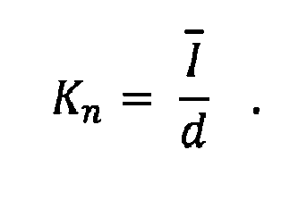
- Gemäß einer vorteilhaften Ausführungsform der Erfindung sind die Einlässe in Richtung des Holweckrotors sich verjüngend ausgebildet. Durch diese in radialer Richtung vorhandene Verjüngung der Einlässe erhält man eine Optimierung der Einlaufströmung, wodurch sich die Leistung der Pumpstufe deutlich verbessert.
- Gemäß einer weiteren vorteilhaften Ausführungsform der Erfindung weist der Holweckstator Kanäle auf und der wenigstens eine Einlass ist im Bereich eines Kanalgrundes angeordnet. Hierdurch bleibt die pumpaktive Struktur des Holweckstators erhalten, obwohl ein Einlass im Bereich des Holweckstators vorgesehen ist.
- Gemäß einer weiteren vorteilhaften Ausführungsform der Erfindung ist der wenigstens eine Einlass ausschließlich in einem Kanalgrund angeordnet. Hierdurch ist gewährleistet, dass die Kanäle des Holweckstators nicht verändert werden und hierdurch eine optimale Pumpwirkung erzielt wird.
- Eine weitere vorteilhafte Ausführungsform der Erfindung sieht vor, dass sämtliche Einlässe im Bereich eines Kanalgrundes angeordnet sind.
- Weitere Merkmale und Vorteile der Erfindung ergeben sich anhand der zugehörigen Zeichnung, in der mehrere Ausführungsbeispiele einer erfindungsgemäßen Vakuumpumpe nur beispielhaft dargestellt sind. In der Zeichnung zeigen:
- Fig. 1
- einen Längsschnitt durch eine Vakuumpumpe mit Holweckpumpstufe;
- Fig. 2
- eine Prinzipdarstellung einer Vakuumpumpe im Längsschnitt;
- Fig. 3
- ein geändertes Ausführungsbeispiel;
- Fig. 4
- einen Längsschnitt durch einen Holweckstator;
- Fig. 5
- einen Querschnitt durch einen Holweckstator,
- Fig. 6
- ein Berechnungsbeispiel einer zum Stand der Technik gehörenden Holweckpumpstufe;
- Fig. 7
- ein Berechnungsbeispiel für eine Holweckpumpstufe gemäß der Erfindung.
- In
Fig. 1 ist eine Vakuumpumpe 1 und ein Kammersystem 2 dargestellt. In einem Kammergehäuse 2 sind eine Vorvakuumkammer 4 und eine Hochvakuumkammer 12 vorgesehen, welche über eine Hochvakuumblende 22 miteinander verbunden sind. Durch eine Vorvakuumblende 14 kann beispielsweise ein Teilchenstrahl in die Vorvakuumkammer 4 gelangen. - Mit dem Kammergehäuse 2 ist ein Pumpengehäuse 40 der Vakuumpumpe 1 vakuumdicht und lösbar verbunden. In einem Pumpengehäuse 40 ist eine Welle 42 angeordnet, welche von einem hochvakuumseitigen Lager 44 und einem vorvakuumseitigen Lager 48 drehbar unterstützt wird.
- Dabei sind beliebige Lagerungen denkbar. Die Lagerung kann zum Beispiel durch zwei Wälzlager realisiert werden, weiterhin kann das vorvakuumseitige Lager als Wälzlager ausgeführt sein und das hochvakuumseitige Lager als Permanentmagnetlager. Auch eine vollmagnetische Lagerung ist möglich.
- Auf der Welle 42 ist ein Permanentmagnet 52 vorgesehen, der mit dem magnetischen Feld einer Antriebsspule 50 zusammenwirkt und damit die Welle 42 in schnelle Drehung versetzt. Schnell bedeutet im Rahmen einer solchen Vakuumpumpe 1, dass die pumpaktiven Bauteile eine Pumpwirkung aufgrund molekularer Mechanismen entfalten und die Drehzahl bei einigen 10.000 Umdrehungen pro Minute liegen.
- Die Vakuumpumpe 1 weist einen ersten Einlass 80 und einen zweiten Einlass 82 auf. Der erste Einlass 80 ist mit der Vorvakuumkammer 4 verbunden, während der zweite Einlass 82 mit der Hochvakuumkammer 12 verbunden ist. Das durch den ersten Einlass 80 in die Vakuumpumpe 1 eintretende Gas gelangt in eine Pumpstufe 70, ebenso wie der zweite Einlass 82. Diese Pumpstufe 70 ist als Holweckpumpstufe ausgebildet mit einem Holweckstator 74 und einem Holweckzylinder 72. Der Holweckstator 74 weist im Wesentlichen einen dickwandigen Hohlzylinder mit gewindeartigen, an seiner Innenseite verlaufenden Kanälen 76 mit viereckigem Querschnitt auf. Innerhalb dieses Zylinders läuft ein mit der Welle 42 verbundener Holweckzylinder 72. Der Holweckzylinder 72 kann aus einem Compound-Material, wie zum Beispiel kohlenstofffaserverstärktem Kunststoff (CFK) hergestellt sein, kann aber auch aus einem Metall, idealerweise einer Aluminiumlegierung bestehen. Dieser umgibt wenigstens teilweise das hochvakuumseitige Lager 44 und einen Lagerträger 46, der dieses Lager 44 am Pumpengehäuse 10 fixiert.
- In der Vakuumpumpe 1 ist eine weitere Pumpstufe 60 vorgesehen. Die Pumpstufe 60 ist als Turbomolekularpumpstufe gestaltet und weist daher jeweils mit einem Schaufelkranz versehene Rotorscheiben 62 und Statorscheiben 64 auf. Diese sind durch Distanzringe 66 axial beabstandet. Die Pumpstufe 60 kann eine Mehrzahl von Rotor- und Statorscheiben umfassen, je nach gefordertem Druckverhältnis zwischen Ansaugbereich und Ausstoßbereich der Pumpstufe. Das Gas wird von der Pumpstufe 60 an einen Auslass 54 der Vakuumpumpe 1 übergeben und verlässt durch diesen die Vakuumpumpe 1.
- Die Turboscheiben 62 können zum Beispiel einzeln auf die Welle 42 gefügt werden, aber auch einstückige Turboscheiben (Glockenrotor) sind möglich.
- Durch den Einlass 80 wird die Vorvakuumkammer 4 evakuiert. Durch den Einlass 82 wird die Hochvakuumkammer 12 evakuiert. Die Einlässe 80 und 82 befinden sich auf verschiedenen Druckniveaus der Holweckpumpstufe 70. Das Druckniveau der Hochvakuumkammer 12 liegt unterhalb des Druckniveaus der Vorvakuumkammer 4.
- Das von der Pumpstufe 70 ausgestoßene Gas wird von der Pumpstufe 60 weitergefördert in Richtung Auslass 54.
- Durch die Anordnung der Einlässe 80 und 82 im Bereich des Holweckstators 74 wird erreicht, dass die hohe Gaslast der Kammer 4 nicht komplett durch die Holweckpumpstufe 70 strömt, sondern lediglich durch einen Teil, so dass der Gasstrom, der durch den Einlass 80 einströmt, einen kürzeren Weg durch die Holweckstufe nimmt. Hierdurch reduziert sich die Gasreibung und besonders die Leistungsaufnahme und die Temperatur.
-
Fig. 2 zeigt die Vakuumpumpe 1 mit einem Kammergehäuse 2. Teile, die mitFig. 1 übereinstimmen, sind mit gleichen Bezugszahlen versehen. In dem Kammergehäuse 2 sind drei Kammern 5, 6, 7 angeordnet. Zwischen den Kammern 5, 6 ist eine Blende 3 und zwischen den Kammern 6, 7 eine Blende 8 angeordnet. In der Blende 3 und in der Blende 8 sind jeweils Öffnungen vorgesehen, so dass in Richtung der dargestellten Pfeile A, B das Gas in die benachbarten Kammern gelangen kann. - Die Holweckpumpstufe 70 mit dem Holweckstator 74 weist zwei Einlässe 11, 13 auf, durch die das Gas aus der Kammer 6 in Richtung der Pfeile C, D in die Holweckpumpstufe 70 gelangen kann. Diese mehreren Einlässe 11, 13 weisen den Vorteil auf, dass sie in axialer Länge der Vakuumpumpstufe 70 verteilt angeordnet sind. Dies hat den Vorteil, dass die hohe Gaslast der entsprechenden Kammer 6 nicht komplett durch einen Einlass 11 der Holweckstufe 70 strömt, sondern sich aufteilt, so dass ein Teil des Gasstromes einen kürzeren Weg durch die Holweckstufe 70 nimmt. Dadurch reduziert sich die Gasreibung und besonders die Leistungsaufnahme und die Temperatur.
- In der Kammer 7 ist ein weiterer Auslass 9 vorgesehen, so dass die Kammer 7 von der Turbomolekularpumpstufe 60 evakuiert wird.
- Durch die Vorvakuumblende 14 kann ein Teilchenstrahl in die Vakuumkammer 5 gelangen.
- Das aus der Kammer 6 in die Holweckpumpstufe 70 austretende Gas wird von der Holweckpumpstufe 70, bestehend aus Holweckstator 74 und Holweckrotor 72, in Richtung der Turbomolekularpumpstufe 60 gefördert und über einen Auslass 54 ausgestoßen.
-
Fig. 3 zeigt die Vakuumpumpe 1 mit einem Kammersystem 2. Gleiche Teile sind mit gleichen Bezugszahlen versehen. - In der Kammer 6 ist eine zusätzliche Blende 15 angeordnet, so dass durch den Einlass 11 im Bereich des Holweckstators 74 circa 80 % des Gases aus der Kammer 6 evakuiert werden und über den Einlass 13 circa 20 %.
- Vorteilhaft weist der Einlass 11 einen größeren Querschnitt auf als der Einlass 13. Das bedeutet, dass der Einlass, der in axialer Richtung näher an der Turbomolekularpumpstufe 60 angeordnet ist, einen kleineren Querschnitt aufweist als der Einlass, der weiter entfernt von der Turbomolekularpumpstufe 60 angeordnet ist.
- Wie in
Fig. 4 dargestellt, weist der Holweckstator 74 Kanäle 76 auf. Gemäß einer vorteilhaften Ausführungsform der Erfindung ist der Einlass 11 im Bereich eines Kanales 76 angeordnet, um im Wesentlichen die Struktur des Holweckstators 74 nicht zu verändern und hierdurch eine optimierte Pumpwirkung zu erzielen. -
Fig. 5 zeigt den Holweckstator 74 mit den Kanälen 76. Radialsymmetrisch verteilt sind Einlässe 11, 16, 17 in dem Holweckstator 74 angeordnet. Diese Einlässe 11, 16, 17 sind in axialer Richtung des Holweckstators 74 gesehen auf einem Druckniveau, das heißt auf gleicher Höhe liegend angeordnet. Der Einlass 16 ist beispielhaft in Richtung Holweckrotor 72 sich verjüngend ausgebildet, die Einlässe können jedoch auch wie der Einlass 11 im Querschnitt zylindrisch ausgebildet sein. - Die Vakuumpumpe kann durch hohe Gasreibung sehr heiß werden. Daher muss in bestimmten Anwendungsfällen die Wärme mittels Kühlung abgeführt werden. Denkbare Kühlungen sind hier eine Konvektionskühlung, eine gezwungene Luftkühlung mittels Lüfter oder eine Wasserkühlung.
-
Fig. 6 zeigt eine Kammer 12, in der eine Gaslast Q von 5 mbar l/s (Liter pro Sekunde) strömt. Die Kammer 12 besitzt eine Anzapfung 82 zu einer Holweckstufe 72, 74. Die einzige Anzapfung 82 hat einen inversen Strömungswiderstand, beziehungsweise Leitwert L von 4 l/s. In der pumpenden Holweckstufe 72, 74 gibt es auf der axialen Höhe der Anzapfung ein nominelles Saugvermögen S 0 von 10 l/s. - Zusammen mit dem Leitwert der Anzapfung 82 gibt es ein effektives Saugvermögen Seff von 2,86 1/s in der Kammer 12. Damit resultiert ein Kammerdruck pKammer von 1,75 mbar.
- In der Holweckstufe 72, 74 selbst stellt sich ein Druck (Holweckdruck) pHW von 0,5 mbar ein. Am Auslass der Holweckstufe beträgt das Saugvermögen am Auslass S 0Auslass = 5 l/s. Damit beträgt der Druck in der Holweckstufe (Auslassdruck Holweckstufe) pAuslass = 1 mbar.
- Die Pumprichtung verläuft in Richtung des Pfeiles E.
- Gemäß
Fig. 7 ist eine erfindungsgemäße Ausführungsform mit zwei Auslässen 80, 82 dargestellt. In der Kammer 12 strömt eine Gaslast Q von 5 mbar l/s. Die Kammer 12 weist die zwei Anzapfungen 80, 82 zu der Holweckstufe 72, 74 auf. Die obere Anzapfung 82 hat einen inversen Strömungswiderstand beziehungsweise Leitwert L 1 von 4 l/s. In der pumpenden Holweckstufe 72, 74 gibt es auf der axialen Höhe der oberen Anzapfung ein nominelles Saugvermögen S 0-1 von 10 l/s. Zusammen mit dem Leitwert der oberen Anzapfung 82 gibt es ein effektives Saugvermögen S eff-1 von 2,86 1/s bei der oberen Anzapfung 82 der Kammer 12. - Die untere Anzapfung 80 hat einen inversen Stömungswiderstand beziehungsweise Leitwert L 2 von 4 l/s. In der pumpenden Holweckstufe 72, 74 gibt es auf der axialen Höhe der unteren Anzapfung ein nominelles Saugvermögen S 0-1 von 5 1/s.
- Zusammen mit dem Leitwert der unteren Anzapfung 80 gibt es ein effektives Saugvermögen S eff-2 von 2,22 l/s bei der unteren Anzapfung 80 der Kammer 12.
- Damit resultiert ein Gesamtsaugvermögen Seff Ges in der Kammer von 5,08 l/s. Damit resultiert ein Kammerdruck pKammer von 0,98 mbar. Die Gaslast beträgt durch die obere Anzapfung Q 1 = 2,81 mbar l/s. Die Gaslast durch die untere Anzapfung beträgt Q 2 = 2,19 mbar l/s. Damit beträgt der Druck an der oberen Anzapfung in der Holweckstufe pHW1 = 0,281 mbar. Der Druck an der unteren Anzapfung in der Holweckstufe beträgt pHW2 = 1 mbar.
- Damit erhält man einen niedrigeren Kammerdruck, eine kleinere Gaslast in dem oberen Teil der Holweckstufe, einen niedrigeren Druck entlang der Holweckstufe und eine geringere Gasreibung in der gesamten Holweckstufe.
-
- 1
- Vakuumpumpe
- 2
- Kammergehäuse
- 3
- Blende
- 4
- Vorvakuumkammer
- 5
- Kammer
- 6
- Kammer
- 7
- Kammer
- 8
- Blende
- 9
- Auslass
- 10
- Pumpengehäuse
- 11
- Einlass
- 12
- Hochvakuumkammer
- 13
- Einlass
- 14
- Vorvakuumblende
- 15
- Blende
- 16
- Einlass
- 17
- Einlass
- 22
- Hochvakuumblende
- 40
- Pumpengehäuse
- 42
- Welle
- 44
- Lager
- 46
- Lagerträger
- 48
- Lager
- 50
- Antriebsspule
- 52
- Permanentmagnet
- 54
- Auslass
- 60
- Turbomolekularpumpstufe
- 62
- Rotorscheibe
- 64
- Statorscheibe
- 66
- Distanzring
- 70
- Holweckpumpstufe
- 72
- Holweckzylinder
- 74
- Holweckstator
- 76
- Kanäle
- 80
- Einlass
- 82
- Einlass
- A
- Pfeil
- B
- Pfeil
- C
- Pfeil
- D
- Pfeil
- E
- Pfeil
Claims (15)
- Vakuumpumpe mit wenigstens einer Holweckpumpstufe mit wenigstens einem Holweckstator und wenigstens einem Holweckrotor,
dadurch gekennzeichnet, dass in dem Holweckstator (74) der wenigstens einen Holweckpumpstufe (70) wenigstens ein Gaseinlass (11, 13, 16, 17) vorgesehen ist. - Vakuumpumpe nach Anspruch 1, dadurch gekennzeichnet, dass in axialer Richtung des Holweckstators (74) wenigstens zwei Einlässe (11, 13) vorgesehen sind.
- Vakuumpumpe nach Anspruch 1 oder 2, dadurch gekennzeichnet, dass in tangentialer Richtung des Holweckstators (74) wenigstens zwei Einlässe (11, 13, 16, 17) vorgesehen sind.
- Vakuumpumpe nach Anspruch 3, dadurch gekennzeichnet, dass die wenigstens zwei Einlässe (11, 13, 16, 17) tangentialsymmetrisch oder asymmetrisch im Holweckstator (74) angeordnet sind.
- Vakuumpumpe nach einem der vorhergehenden Ansprüche, dadurch gekennzeichnet, dass der wenigstens eine Einlass (11, 13, 16, 17) als Bohrung und/oder Langloch und/oder Schlitz ausgebildet ist.
- Vakuumpumpe nach einem der vorhergehenden Ansprüche, dadurch gekennzeichnet, dass die Einlässe (11, 13, 16, 17) gleiche oder unterschiedliche Querschnitte aufweisen.
- Vakuumpumpe nach einem der vorhergehenden Ansprüche, dadurch gekennzeichnet, dass jeder Einlass (11, 13) mit lediglich einer zu evakuierenden Kammer verbunden ist.
- Vakuumpumpe nach einem der vorhergehenden Ansprüche, dadurch gekennzeichnet, dass mehrere Einlässe (11, 13, 16, 17) mit lediglich einer zu evakuierenden Kammer (6) verbunden sind.
- Vakuumpumpe nach einem der vorhergehenden Ansprüche, dadurch gekennzeichnet, dass die Vakuumpumpe (1) wenigstens eine zusätzliche Turbomolekularpumpstufe (60) aufweist.
- Vakuumpumpe nach Anspruch 9, dadurch gekennzeichnet, dass in dem Holweckstator (74) wenigstens zwei Einlässe (11, 13, 80, 82) angeordnet sind, und dass der Einlass (13, 80), der in axialer Richtung der Vakuumpumpe (1) näher an der Turbomolekularpumpstufe (60) angeordnet ist, als ein im Bereich molekularer Strömung angeordneter Einlass (11, 80) ausgebildet ist.
- Vakuumpumpe nach Anspruch 9, dadurch gekennzeichnet, dass in dem Holweckstator (74) wenigstens zwei Einlässe (11, 13, 80, 82) angeordnet sind, und dass der Einlass (11, 82), der in axialer Richtung der Vakuumpumpe (1) weiter weg von der Turbomolekularpumpstufe (60) angeordnet ist, als ein im Bereich einer Knudsen-Strömung angeordneter Einlass (11, 82) ausgebildet ist.
- Vakuumpumpe nach einem der vorhergehenden Ansprüche, dadurch gekennzeichnet, dass der wenigstens eine Einlass (11, 82) im Hochvakuumbereich einen größeren Querschnitt aufweist als der wenigstens eine Einlass (13, 80) im Vorvakuumbereich.
- Vakuumpumpe nach einem der vorhergehenden Ansprüche, dadurch gekennzeichnet, dass an dem wenigstens einen Einlass (11, 13, 80, 82) ein Druck von 1 bis 100 Pascal anliegt.
- Vakuumpumpe nach einem der vorhergehenden Ansprüche, dadurch gekennzeichnet, dass die Einlässe (16) in Richtung des Holweckrotors (72) sich verjüngend ausgebildet sind.
- Vakuumpumpe nach einem der vorhergehenden Ansprüche, dadurch gekennzeichnet, dass der Holweckstator (74) Kanäle (76) aufweist, und dass der wenigstens eine Einlass (11, 13, 16, 17, 80, 82) im Bereich eines Kanalgrundes angeordnet ist oder dass der wenigstens eine Einlass (11, 13, 16, 17, 80, 82) ausschließlich in einem Kanalgrund angeordnet ist oder dass sämtliche Einlässe (11, 13, 16, 17, 80, 82) im Bereich eines Kanalgrundes angeordnet sind.
Applications Claiming Priority (1)
| Application Number | Priority Date | Filing Date | Title |
|---|---|---|---|
| DE102014101257.7A DE102014101257A1 (de) | 2014-02-03 | 2014-02-03 | Vakuumpumpe |
Publications (3)
| Publication Number | Publication Date |
|---|---|
| EP2902637A2 true EP2902637A2 (de) | 2015-08-05 |
| EP2902637A3 EP2902637A3 (de) | 2015-09-02 |
| EP2902637B1 EP2902637B1 (de) | 2017-11-08 |
Family
ID=52278512
Family Applications (1)
| Application Number | Title | Priority Date | Filing Date |
|---|---|---|---|
| EP15150410.7A Active EP2902637B1 (de) | 2014-02-03 | 2015-01-08 | Vakuumpumpe |
Country Status (2)
| Country | Link |
|---|---|
| EP (1) | EP2902637B1 (de) |
| DE (1) | DE102014101257A1 (de) |
Cited By (1)
| Publication number | Priority date | Publication date | Assignee | Title |
|---|---|---|---|---|
| CN106523394A (zh) * | 2015-09-15 | 2017-03-22 | 株式会社岛津制作所 | 真空泵及质量分析装置 |
Citations (1)
| Publication number | Priority date | Publication date | Assignee | Title |
|---|---|---|---|---|
| EP1668255B1 (de) | 2003-09-30 | 2011-11-30 | Edwards Limited | Vakuumpumpe |
Family Cites Families (7)
| Publication number | Priority date | Publication date | Assignee | Title |
|---|---|---|---|---|
| US5733104A (en) * | 1992-12-24 | 1998-03-31 | Balzers-Pfeiffer Gmbh | Vacuum pump system |
| DE10302987A1 (de) * | 2003-01-25 | 2004-08-05 | Inficon Gmbh | Lecksuchgerät mit einem Einlass |
| DE10308420A1 (de) * | 2003-02-27 | 2004-09-09 | Leybold Vakuum Gmbh | Testgaslecksuchgerät |
| DE202005019644U1 (de) * | 2005-12-16 | 2007-04-26 | Leybold Vacuum Gmbh | Turbomolekularpumpe |
| DE102008024764A1 (de) * | 2008-05-23 | 2009-11-26 | Oerlikon Leybold Vacuum Gmbh | Mehrstufige Vakuumpumpe |
| DE102009035332A1 (de) * | 2009-07-30 | 2011-02-03 | Pfeiffer Vacuum Gmbh | Vakuumpumpe |
| JP5948349B2 (ja) * | 2011-02-03 | 2016-07-06 | オーリコン レイボルド バキューム ゲーエムベーハー | 漏れ検出デバイス |
-
2014
- 2014-02-03 DE DE102014101257.7A patent/DE102014101257A1/de active Pending
-
2015
- 2015-01-08 EP EP15150410.7A patent/EP2902637B1/de active Active
Patent Citations (1)
| Publication number | Priority date | Publication date | Assignee | Title |
|---|---|---|---|---|
| EP1668255B1 (de) | 2003-09-30 | 2011-11-30 | Edwards Limited | Vakuumpumpe |
Cited By (1)
| Publication number | Priority date | Publication date | Assignee | Title |
|---|---|---|---|---|
| CN106523394A (zh) * | 2015-09-15 | 2017-03-22 | 株式会社岛津制作所 | 真空泵及质量分析装置 |
Also Published As
| Publication number | Publication date |
|---|---|
| DE102014101257A1 (de) | 2015-08-06 |
| EP2902637B1 (de) | 2017-11-08 |
| EP2902637A3 (de) | 2015-09-02 |
Similar Documents
| Publication | Publication Date | Title |
|---|---|---|
| DE602004008089T2 (de) | Vakuumpumpe | |
| DE2412624C2 (de) | Molekularvakuumpumpenanordnung | |
| EP2295812B1 (de) | Vakuumpumpe | |
| EP0697069A1 (de) | Reibungsvakuumpumpe mit unterschiedlich gestalteten pumpenabschnitten | |
| EP2933497B1 (de) | Vakuumpumpe | |
| DE29516599U1 (de) | Reibungsvakuumpumpe mit Zwischeneinlaß | |
| EP1706645B1 (de) | Mehrstufige reibungsvakuumpumpe | |
| DE102012003680A1 (de) | Vakuumpumpe | |
| EP3012459B1 (de) | Vakuumpumpe | |
| EP1067290B1 (de) | Vakuumpumpe | |
| EP3112688B1 (de) | Splitflow-vakuumpumpe sowie vakuum-system mit einer splitflow-vakuumpumpe | |
| EP3460249B1 (de) | Splitflow-vakuumpumpe | |
| EP3104014B1 (de) | Seitenkanal-vakuumpumpstufe mit einem kanalquerschnitt, der eine bestimmte krümmung aufweist | |
| EP2902637B1 (de) | Vakuumpumpe | |
| EP2565464B1 (de) | Vakuumpumpe | |
| EP0825346A1 (de) | Eingangsstufe für eine zweiflutige Gasreibungspumpe | |
| EP2886870B1 (de) | Vakuumpumpe mit verbesserter Einlassgeometrie | |
| DE102015111049B4 (de) | Vakuumpumpe | |
| DE102015100048B4 (de) | Anordnung zur Lagerung einer Welle einer Vakuumpumpe | |
| DE102013112185B4 (de) | Vakuumpumpe sowie Vakuumpumpe mit wenigstens einer Turbomolekularpumpstufe | |
| EP3767109B1 (de) | Vakuumsystem | |
| DE102012110029A1 (de) | Turbomaschine zur Verdichtung eines gas- oder dampfförmigen Fluids | |
| EP3067567A1 (de) | Vakuumpumpe | |
| EP3032106A1 (de) | Vakuumpumpe | |
| DE102013022539B3 (de) | Vakuumpumpe |
Legal Events
| Date | Code | Title | Description |
|---|---|---|---|
| PUAL | Search report despatched |
Free format text: ORIGINAL CODE: 0009013 |
|
| PUAI | Public reference made under article 153(3) epc to a published international application that has entered the european phase |
Free format text: ORIGINAL CODE: 0009012 |
|
| 17P | Request for examination filed |
Effective date: 20150108 |
|
| AK | Designated contracting states |
Kind code of ref document: A2 Designated state(s): AL AT BE BG CH CY CZ DE DK EE ES FI FR GB GR HR HU IE IS IT LI LT LU LV MC MK MT NL NO PL PT RO RS SE SI SK SM TR |
|
| AX | Request for extension of the european patent |
Extension state: BA ME |
|
| AK | Designated contracting states |
Kind code of ref document: A3 Designated state(s): AL AT BE BG CH CY CZ DE DK EE ES FI FR GB GR HR HU IE IS IT LI LT LU LV MC MK MT NL NO PL PT RO RS SE SI SK SM TR |
|
| AX | Request for extension of the european patent |
Extension state: BA ME |
|
| RIC1 | Information provided on ipc code assigned before grant |
Ipc: F04D 19/04 20060101AFI20150730BHEP Ipc: F04D 29/70 20060101ALI20150730BHEP |
|
| 17P | Request for examination filed |
Effective date: 20160224 |
|
| RBV | Designated contracting states (corrected) |
Designated state(s): AL AT BE BG CH CY CZ DE DK EE ES FI FR GB GR HR HU IE IS IT LI LT LU LV MC MK MT NL NO PL PT RO RS SE SI SK SM TR |
|
| GRAP | Despatch of communication of intention to grant a patent |
Free format text: ORIGINAL CODE: EPIDOSNIGR1 |
|
| INTG | Intention to grant announced |
Effective date: 20170718 |
|
| GRAS | Grant fee paid |
Free format text: ORIGINAL CODE: EPIDOSNIGR3 |
|
| GRAA | (expected) grant |
Free format text: ORIGINAL CODE: 0009210 |
|
| AK | Designated contracting states |
Kind code of ref document: B1 Designated state(s): AL AT BE BG CH CY CZ DE DK EE ES FI FR GB GR HR HU IE IS IT LI LT LU LV MC MK MT NL NO PL PT RO RS SE SI SK SM TR |
|
| REG | Reference to a national code |
Ref country code: GB Ref legal event code: FG4D Free format text: NOT ENGLISH |
|
| REG | Reference to a national code |
Ref country code: CH Ref legal event code: EP Ref country code: AT Ref legal event code: REF Ref document number: 944406 Country of ref document: AT Kind code of ref document: T Effective date: 20171115 |
|
| REG | Reference to a national code |
Ref country code: IE Ref legal event code: FG4D Free format text: LANGUAGE OF EP DOCUMENT: GERMAN |
|
| REG | Reference to a national code |
Ref country code: DE Ref legal event code: R096 Ref document number: 502015002272 Country of ref document: DE |
|
| REG | Reference to a national code |
Ref country code: NL Ref legal event code: MP Effective date: 20171108 |
|
| REG | Reference to a national code |
Ref country code: LT Ref legal event code: MG4D |
|
| PG25 | Lapsed in a contracting state [announced via postgrant information from national office to epo] |
Ref country code: ES Free format text: LAPSE BECAUSE OF FAILURE TO SUBMIT A TRANSLATION OF THE DESCRIPTION OR TO PAY THE FEE WITHIN THE PRESCRIBED TIME-LIMIT Effective date: 20171108 Ref country code: LT Free format text: LAPSE BECAUSE OF FAILURE TO SUBMIT A TRANSLATION OF THE DESCRIPTION OR TO PAY THE FEE WITHIN THE PRESCRIBED TIME-LIMIT Effective date: 20171108 Ref country code: NL Free format text: LAPSE BECAUSE OF FAILURE TO SUBMIT A TRANSLATION OF THE DESCRIPTION OR TO PAY THE FEE WITHIN THE PRESCRIBED TIME-LIMIT Effective date: 20171108 Ref country code: NO Free format text: LAPSE BECAUSE OF FAILURE TO SUBMIT A TRANSLATION OF THE DESCRIPTION OR TO PAY THE FEE WITHIN THE PRESCRIBED TIME-LIMIT Effective date: 20180208 Ref country code: SE Free format text: LAPSE BECAUSE OF FAILURE TO SUBMIT A TRANSLATION OF THE DESCRIPTION OR TO PAY THE FEE WITHIN THE PRESCRIBED TIME-LIMIT Effective date: 20171108 Ref country code: FI Free format text: LAPSE BECAUSE OF FAILURE TO SUBMIT A TRANSLATION OF THE DESCRIPTION OR TO PAY THE FEE WITHIN THE PRESCRIBED TIME-LIMIT Effective date: 20171108 |
|
| PG25 | Lapsed in a contracting state [announced via postgrant information from national office to epo] |
Ref country code: RS Free format text: LAPSE BECAUSE OF FAILURE TO SUBMIT A TRANSLATION OF THE DESCRIPTION OR TO PAY THE FEE WITHIN THE PRESCRIBED TIME-LIMIT Effective date: 20171108 Ref country code: GR Free format text: LAPSE BECAUSE OF FAILURE TO SUBMIT A TRANSLATION OF THE DESCRIPTION OR TO PAY THE FEE WITHIN THE PRESCRIBED TIME-LIMIT Effective date: 20180209 Ref country code: BG Free format text: LAPSE BECAUSE OF FAILURE TO SUBMIT A TRANSLATION OF THE DESCRIPTION OR TO PAY THE FEE WITHIN THE PRESCRIBED TIME-LIMIT Effective date: 20180208 Ref country code: HR Free format text: LAPSE BECAUSE OF FAILURE TO SUBMIT A TRANSLATION OF THE DESCRIPTION OR TO PAY THE FEE WITHIN THE PRESCRIBED TIME-LIMIT Effective date: 20171108 Ref country code: IS Free format text: LAPSE BECAUSE OF FAILURE TO SUBMIT A TRANSLATION OF THE DESCRIPTION OR TO PAY THE FEE WITHIN THE PRESCRIBED TIME-LIMIT Effective date: 20180308 Ref country code: LV Free format text: LAPSE BECAUSE OF FAILURE TO SUBMIT A TRANSLATION OF THE DESCRIPTION OR TO PAY THE FEE WITHIN THE PRESCRIBED TIME-LIMIT Effective date: 20171108 |
|
| PG25 | Lapsed in a contracting state [announced via postgrant information from national office to epo] |
Ref country code: CY Free format text: LAPSE BECAUSE OF FAILURE TO SUBMIT A TRANSLATION OF THE DESCRIPTION OR TO PAY THE FEE WITHIN THE PRESCRIBED TIME-LIMIT Effective date: 20171108 Ref country code: SK Free format text: LAPSE BECAUSE OF FAILURE TO SUBMIT A TRANSLATION OF THE DESCRIPTION OR TO PAY THE FEE WITHIN THE PRESCRIBED TIME-LIMIT Effective date: 20171108 Ref country code: EE Free format text: LAPSE BECAUSE OF FAILURE TO SUBMIT A TRANSLATION OF THE DESCRIPTION OR TO PAY THE FEE WITHIN THE PRESCRIBED TIME-LIMIT Effective date: 20171108 Ref country code: DK Free format text: LAPSE BECAUSE OF FAILURE TO SUBMIT A TRANSLATION OF THE DESCRIPTION OR TO PAY THE FEE WITHIN THE PRESCRIBED TIME-LIMIT Effective date: 20171108 |
|
| REG | Reference to a national code |
Ref country code: DE Ref legal event code: R097 Ref document number: 502015002272 Country of ref document: DE |
|
| PG25 | Lapsed in a contracting state [announced via postgrant information from national office to epo] |
Ref country code: PL Free format text: LAPSE BECAUSE OF FAILURE TO SUBMIT A TRANSLATION OF THE DESCRIPTION OR TO PAY THE FEE WITHIN THE PRESCRIBED TIME-LIMIT Effective date: 20171108 Ref country code: RO Free format text: LAPSE BECAUSE OF FAILURE TO SUBMIT A TRANSLATION OF THE DESCRIPTION OR TO PAY THE FEE WITHIN THE PRESCRIBED TIME-LIMIT Effective date: 20171108 Ref country code: SM Free format text: LAPSE BECAUSE OF FAILURE TO SUBMIT A TRANSLATION OF THE DESCRIPTION OR TO PAY THE FEE WITHIN THE PRESCRIBED TIME-LIMIT Effective date: 20171108 |
|
| REG | Reference to a national code |
Ref country code: CH Ref legal event code: PL |
|
| PLBE | No opposition filed within time limit |
Free format text: ORIGINAL CODE: 0009261 |
|
| STAA | Information on the status of an ep patent application or granted ep patent |
Free format text: STATUS: NO OPPOSITION FILED WITHIN TIME LIMIT |
|
| PG25 | Lapsed in a contracting state [announced via postgrant information from national office to epo] |
Ref country code: MT Free format text: LAPSE BECAUSE OF FAILURE TO SUBMIT A TRANSLATION OF THE DESCRIPTION OR TO PAY THE FEE WITHIN THE PRESCRIBED TIME-LIMIT Effective date: 20171108 |
|
| 26N | No opposition filed |
Effective date: 20180809 |
|
| PG25 | Lapsed in a contracting state [announced via postgrant information from national office to epo] |
Ref country code: FR Free format text: LAPSE BECAUSE OF NON-PAYMENT OF DUE FEES Effective date: 20180131 Ref country code: LU Free format text: LAPSE BECAUSE OF NON-PAYMENT OF DUE FEES Effective date: 20180108 |
|
| REG | Reference to a national code |
Ref country code: IE Ref legal event code: MM4A |
|
| REG | Reference to a national code |
Ref country code: FR Ref legal event code: ST Effective date: 20180928 |
|
| REG | Reference to a national code |
Ref country code: BE Ref legal event code: MM Effective date: 20180131 |
|
| PG25 | Lapsed in a contracting state [announced via postgrant information from national office to epo] |
Ref country code: BE Free format text: LAPSE BECAUSE OF NON-PAYMENT OF DUE FEES Effective date: 20180131 Ref country code: SI Free format text: LAPSE BECAUSE OF FAILURE TO SUBMIT A TRANSLATION OF THE DESCRIPTION OR TO PAY THE FEE WITHIN THE PRESCRIBED TIME-LIMIT Effective date: 20171108 Ref country code: LI Free format text: LAPSE BECAUSE OF NON-PAYMENT OF DUE FEES Effective date: 20180131 Ref country code: CH Free format text: LAPSE BECAUSE OF NON-PAYMENT OF DUE FEES Effective date: 20180131 |
|
| PG25 | Lapsed in a contracting state [announced via postgrant information from national office to epo] |
Ref country code: IE Free format text: LAPSE BECAUSE OF NON-PAYMENT OF DUE FEES Effective date: 20180108 |
|
| PG25 | Lapsed in a contracting state [announced via postgrant information from national office to epo] |
Ref country code: MC Free format text: LAPSE BECAUSE OF FAILURE TO SUBMIT A TRANSLATION OF THE DESCRIPTION OR TO PAY THE FEE WITHIN THE PRESCRIBED TIME-LIMIT Effective date: 20171108 |
|
| PG25 | Lapsed in a contracting state [announced via postgrant information from national office to epo] |
Ref country code: TR Free format text: LAPSE BECAUSE OF FAILURE TO SUBMIT A TRANSLATION OF THE DESCRIPTION OR TO PAY THE FEE WITHIN THE PRESCRIBED TIME-LIMIT Effective date: 20171108 |
|
| PG25 | Lapsed in a contracting state [announced via postgrant information from national office to epo] |
Ref country code: PT Free format text: LAPSE BECAUSE OF FAILURE TO SUBMIT A TRANSLATION OF THE DESCRIPTION OR TO PAY THE FEE WITHIN THE PRESCRIBED TIME-LIMIT Effective date: 20171108 |
|
| PG25 | Lapsed in a contracting state [announced via postgrant information from national office to epo] |
Ref country code: MK Free format text: LAPSE BECAUSE OF NON-PAYMENT OF DUE FEES Effective date: 20171108 Ref country code: HU Free format text: LAPSE BECAUSE OF FAILURE TO SUBMIT A TRANSLATION OF THE DESCRIPTION OR TO PAY THE FEE WITHIN THE PRESCRIBED TIME-LIMIT; INVALID AB INITIO Effective date: 20150108 |
|
| PG25 | Lapsed in a contracting state [announced via postgrant information from national office to epo] |
Ref country code: AL Free format text: LAPSE BECAUSE OF FAILURE TO SUBMIT A TRANSLATION OF THE DESCRIPTION OR TO PAY THE FEE WITHIN THE PRESCRIBED TIME-LIMIT Effective date: 20171108 |
|
| REG | Reference to a national code |
Ref country code: AT Ref legal event code: MM01 Ref document number: 944406 Country of ref document: AT Kind code of ref document: T Effective date: 20200108 |
|
| PG25 | Lapsed in a contracting state [announced via postgrant information from national office to epo] |
Ref country code: AT Free format text: LAPSE BECAUSE OF NON-PAYMENT OF DUE FEES Effective date: 20200108 |
|
| PGFP | Annual fee paid to national office [announced via postgrant information from national office to epo] |
Ref country code: GB Payment date: 20251216 Year of fee payment: 12 |
|
| PGFP | Annual fee paid to national office [announced via postgrant information from national office to epo] |
Ref country code: CZ Payment date: 20251118 Year of fee payment: 12 |
|
| PGFP | Annual fee paid to national office [announced via postgrant information from national office to epo] |
Ref country code: DE Payment date: 20251126 Year of fee payment: 12 |
|
| PGFP | Annual fee paid to national office [announced via postgrant information from national office to epo] |
Ref country code: IT Payment date: 20251126 Year of fee payment: 12 |