EP2902001B1 - Tragbare Spa-Konstruktion - Google Patents
Tragbare Spa-Konstruktion Download PDFInfo
- Publication number
- EP2902001B1 EP2902001B1 EP14187046.9A EP14187046A EP2902001B1 EP 2902001 B1 EP2902001 B1 EP 2902001B1 EP 14187046 A EP14187046 A EP 14187046A EP 2902001 B1 EP2902001 B1 EP 2902001B1
- Authority
- EP
- European Patent Office
- Prior art keywords
- spa
- spa structure
- pivot
- component
- panel
- Prior art date
- Legal status (The legal status is an assumption and is not a legal conclusion. Google has not performed a legal analysis and makes no representation as to the accuracy of the status listed.)
- Not-in-force
Links
Images












Classifications
-
- A—HUMAN NECESSITIES
- A47—FURNITURE; DOMESTIC ARTICLES OR APPLIANCES; COFFEE MILLS; SPICE MILLS; SUCTION CLEANERS IN GENERAL
- A47K—SANITARY EQUIPMENT; ACCESSORIES THEREFOR, e.g. TOILET ACCESSORIES
- A47K3/00—Baths; Showers; Appurtenances therefor
- A47K3/02—Baths
- A47K3/06—Collapsible baths, e.g. inflatable; Movable baths
-
- A—HUMAN NECESSITIES
- A61—MEDICAL OR VETERINARY SCIENCE; HYGIENE
- A61H—PHYSICAL THERAPY APPARATUS, e.g. DEVICES FOR LOCATING OR STIMULATING REFLEX POINTS IN THE BODY; ARTIFICIAL RESPIRATION; MASSAGE; BATHING DEVICES FOR SPECIAL THERAPEUTIC OR HYGIENIC PURPOSES OR SPECIFIC PARTS OF THE BODY
- A61H33/00—Bathing devices for special therapeutic or hygienic purposes
- A61H33/0087—Therapeutic baths with agitated or circulated water
-
- A—HUMAN NECESSITIES
- A61—MEDICAL OR VETERINARY SCIENCE; HYGIENE
- A61H—PHYSICAL THERAPY APPARATUS, e.g. DEVICES FOR LOCATING OR STIMULATING REFLEX POINTS IN THE BODY; ARTIFICIAL RESPIRATION; MASSAGE; BATHING DEVICES FOR SPECIAL THERAPEUTIC OR HYGIENIC PURPOSES OR SPECIFIC PARTS OF THE BODY
- A61H33/00—Bathing devices for special therapeutic or hygienic purposes
- A61H33/02—Bathing devices for use with gas-containing liquid, or liquid in which gas is led or generated, e.g. carbon dioxide baths
-
- A—HUMAN NECESSITIES
- A61—MEDICAL OR VETERINARY SCIENCE; HYGIENE
- A61H—PHYSICAL THERAPY APPARATUS, e.g. DEVICES FOR LOCATING OR STIMULATING REFLEX POINTS IN THE BODY; ARTIFICIAL RESPIRATION; MASSAGE; BATHING DEVICES FOR SPECIAL THERAPEUTIC OR HYGIENIC PURPOSES OR SPECIFIC PARTS OF THE BODY
- A61H33/00—Bathing devices for special therapeutic or hygienic purposes
- A61H33/60—Components specifically designed for the therapeutic baths of groups A61H33/00
- A61H33/6005—Special constructive structural details of the bathtub, e.g. of the walls or supporting structure
-
- A—HUMAN NECESSITIES
- A61—MEDICAL OR VETERINARY SCIENCE; HYGIENE
- A61H—PHYSICAL THERAPY APPARATUS, e.g. DEVICES FOR LOCATING OR STIMULATING REFLEX POINTS IN THE BODY; ARTIFICIAL RESPIRATION; MASSAGE; BATHING DEVICES FOR SPECIAL THERAPEUTIC OR HYGIENIC PURPOSES OR SPECIFIC PARTS OF THE BODY
- A61H2201/00—Characteristics of apparatus not provided for in the preceding codes
- A61H2201/01—Constructive details
- A61H2201/0107—Constructive details modular
Definitions
- the subject disclosure relates to a spa structure.
- Portable spas have become quite popular as a result of their ease of use and multiplicity of features such as varied jet and seating configurations.
- US Patent Application No. 2009/211011 discloses a spa with panel systems to constrain panels relative to a spa but allow them to be readily removed to permit replacement of the panels.
- a panel is constrained from removal using flanges that may be attached to a frame of the spa and can be at least partially removed.
- the panel can be free to float within the confines of the flanges to accommodate expansion and contraction of the panel.
- US Patent Application No. 2004/103472 discloses a structure for an above-ground swimming pool comprising cladding panels that are slid into grooves of consecutive posts.
- the grooves are so situated to allow a separation between the cladding panels and the rigid wall of the swimming pool in order to provide ventilation and keep moisture away from the cladding panels.
- the cladding panels comprise stacked planks or boards with tenoned edges for insertion into the grooves of the posts.
- German Patent Application No. 2825146 discloses apparatus for mounting panelling onto the sides of a bathtub.
- the panelling includes upper and lower flanged edges, to which attachment members are fixed.
- the upper attachment member engages an upper flanged edge of the bathtub and the lower attachment member locks in place by pushing down a spring plate mounted on the bathtub and engaging a flanged end of the spring plate with a groove.
- a spa structure comprising a plurality of corner pieces, each positioned at a respective corner of the structure and a plurality of trapezoidal shaped side panels positioned between the corner pieces.
- Each side panel is positioned with its respective side edges located in grooves defined by the corner pieces and their mounting brackets such that each side panel may move or slide both horizontally and vertically with respect to the corner pieces and other structural parts so as to accommodate expansion or contraction of the side panels.
- a lower edge of each side panel is held in place by a plurality of panel clips, each of which is pivotable into and out of a panel retaining position, which facilitates panel installation and disassembly.
- Such an illustrative structure may further include a generally rectangular base pan of smaller width and length than a generally rectangular outer upper rim of the spa, with the base pan being centrally positioned within and beneath the outer upper rim and including a plurality of downwardly and inwardly swept back lower side surfaces extending from the lower edges of the side panels to lower edges of the base pan.
- a plurality of vertical support members are configured to support an upper rim of a spa shell, and a plurality of angled force transfer members are attached at respective lower ends of the vertical support members to transfer force from each respective vertical support member to an inner bottom surface of the base pan.
- Fig. 1 illustrates a portable spa 11 having a spa shell 13, side panels, e.g., 15, 17 and tapered corner fascia pieces, e.g., 19, 21, 23.
- the spa shell 11 has a generally rectangular rim 12 about its upper periphery and includes various features such as jets, e.g. 25, 27, a filter compartment 29 and a remote control 31.
- jets e.g. 25, 27, a filter compartment 29 and a remote control 31.
- the lower edges 33 of the side panels 15, 17 do not extend to the bottom edges 35 of the corner pieces 19, 21, 23 but rather terminate at a distance "d" ( Fig. 2 ) above the slab, deck, ground or other surface 30 on which the spa rests, such distance "d" being, for example, 6 inches (about 15 centimetres) in one embodiment.
- the corner pieces e.g., 19, 21, 23, are slightly spaced above, and do not contact, the surface 30.
- the side panels 15, 17 are trapezoidal in shape in one illustrative embodiment.
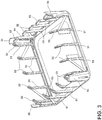
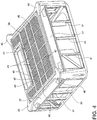
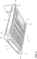
- the spa 11 further includes a base pan 39 shown in Figs. 2 , 4 , and 5 .
- the lower peripheral side surfaces 37 of the base pan 39 are recessed inwardly or swept back from the side panel edges 33 to provide a pedestal effect, giving the appearance that the spa 11 contacts the floor 35 only at its four corners and at the recessed edge 36 of the base pan 39.
- the spa base pan 39 itself has four corners 40, each of which lies within and is concealed by a respective corner fascia piece, e.g. 19, 21, 23.
- the bottom of the base pan 39 further includes a grid work of rectangular areas 41 which include recessed fins or "thermal separators" 43.
- the grid work is defined by perpendicularly disposed ribs 45, 47, whose flat bottom surfaces also rest on the surface 30.
- the rib and thermal separator structure on the bottom of the base pan 39 minimizes the surface area of the base pan 39 which is in contact with the surface 30 and, hence, reduces heat transfer from the spa 11 to the surface 30.
- a wavelike shape is imparted to the ribs, assisting in the minimizing the contact area.
- angled force transfer members 53 for example, by gluing, snap-fitting, or other fastening mechanism.
- Fig. 6 particularly shows the interfitting relationship of the base pan side surface 37 and the force transfer members 53 according to an illustrative embodiment.
- the side surface 37 has an inner horizontally disposed top step 42 and a horizontally disposed lower step 44.
- the angled force transfer member 53 includes a stepped edge 46 shaped to mate with the step 42.
- the stepped edge 46 forms into an angled surface 48, which rests on the swept back surface 37.
- the angled surface 48 continues into a second step 43, which mates with the lower step 44.
- a slot or channel 50 is further formed in the base pan 39 and snugly receives a foot portion 34 of the angled force transfer member 53.
- Mating surfaces of the base pan surface 37 and the force transfer member 53 may be glued, snap-fitted, or otherwise fastened together in position in various embodiments.
- the vertical support member 51 and the angled force transfer member 53 may be fabricated of extruded ABS plastic and injection molded ABS plastic, respectively.
- the base pan 39 may be a thermoformed ABS plastic sheet. Other materials and fabrication techniques may of course be used in other embodiments.
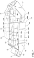
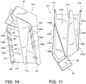
- the force transfer member 53 may be a two piece component comprising respective halves 131,133, as shown in Figs. 7 to 15 .
- the halves 131, 133 are mated together utilizing two tabs 141, 143, formed on the first half 131 and two tabs 150, 151 formed on the second half 133.
- These tabs 141, 143; 150, 151 may be seen in Figs. 11 and 10 , respectively.
- the interior 137 of the first half 131 may have height markers, e.g. "29", “33”, “36", “38” molded or formed therein or applied thereto and located adjacent respective slots 139a, 139b, 139c, and 139d to indicate the particular spa rim height which can be accommodated by utilizing a particular slot.
- the two tabs 150, 151 on half 133 e.g. Fig.
- the first half 131 can be telescoped between positions -38-, - 36-, -33-, -28- to increase or decrease the length of the angled force transfer member 53 and can be locked in position by the tabs 150, 151, as further described below.
- first and second halves 131, 133 are attached together.
- the tab 150 is riding in the second groove 135c.
- the tab 151 is also riding in a generally parallel groove 134c on the opposite side of the first half 131.
- the tabs 141, 143 of the first half are passing through grooves 139b, 140b ( Fig. 10 ) of the second half 133, thereby selecting the height of -33- inches (about 84 centimetres).
- the tabs 150, 151 reach the end of the respective grooves 135c, 134c, they snap down over the side surface 136 of the component 131, e.g., as shown in Fig.
- Figs. 12 and 13 illustrate the -28- inch (about 71 centimetres) assembly position, whereas the assembly shown in Fig. 7 would result in tabs 150, 151 being positioned one groove up (135c, 134c) and the tabs 141, 143 being positioned one slot down from the positions shown in Figs. 12 and 13 .
- the first half 131 has a tongue 171 and a cavity 174 formed in its interior
- the second half 133 has a cavity 172 and a tongue 173 formed in its interior.
- the tongue 171 on the interior of the first half 131 fits into the cavity 172 in the second half 133
- the tongue 173 of the second half 133 fits into the cavity 174 formed in the first half 131.
- the first half 131 further has an open or "cut-out" area 162 of rectangular cross-section formed therein ( Fig. 7 ).
- the area 162 has a shape identical to that of area 161 ( Fig. 9 ). Additional open or hollow areas, e.g., 164 and area 165 ( Fig. 8 ), are formed in the components 131, 133 to capture foam sprayed into the interior of the spa shell to thereby create a rigid foam/plastic structure.
- the illustrative angle force transfer member 53 has an upper receptacle of generally rectangular cross-section formed as a part thereof having a rectangular rim 47 and a hollow interior 143.
- First and second u-shaped projections 201, 202 are formed in the hollow interior 143.
- the lower end of a vertical support member 51 is configured to snugly mate or snap fit with the structure of the receptacle 141.
- each side panel 33 may be slid into position and retained in place without abutting or being attached to the corner pieces 19, 21, 23 or other spa structure.
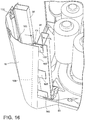
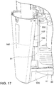
- corner piece groove structures 65 are provided as shown in Figs. 16 and 17
- three panel clips 69 are positioned along a lower surface 72 of the base pan 39, as shown in Fig. 18 . While three panel clips 69 are shown in Fig. 18 , the number of clips could be one, two, or more in various embodiments.
- Fig. 16 illustrates attachment of one of the tapered corner pieces 19 to respective vertical support members 51 using a number of "U"-shaped brackets 105.
- a first leg of each bracket 105 attaches to the support member 51 and a second leg attaches to the corner piece 19.
- the length "L" of the first leg of each bracket 105 increases as the edge 107 of the corner piece 19 tapers away downwardly.
- the angle ⁇ ( Fig. 17 ) between the corner piece's tapered edge 107 and the vertical is an acute angle, for example, such as six or seven degrees.
- the increasing bracket length effectively defines a gap or groove 65 between the brackets 105 and the corner piece 19 which lies along the dashed line 109, effectively paralleling the tapered outside edge 107.
- the same type of groove 65 is formed by U-shaped brackets 105 associated with each of the other three corner pieces, e.g., 21, 23.
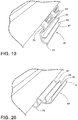
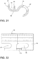
- Each panel clip 69 includes a pivot component 73 ( Figs. 23, 24 ) and a latch component 75 ( Figs. 21, 22 ).
- the latch component 75 has a hook-shaped back 79, which is unitarily formed with a front portion 80 having first and second lips 81, 83, whose inner surfaces define a channel 85.
- the hook-shaped back 79 includes a slot 87 and an elongated opening 89.
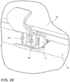
- the pivot component 73 has an arcuate back surface 78 from which project two bosses 120 through which are formed respective holes 77. As illustrated in Figs. 28 and 29 , respective screws or other fasteners 82 are inserted through the holes and into a side surface 72 of the molded base pan 39. The bosses 120 cause the arcuate back surface 78 to be spaced apart from the side surface 72 such that the hook shaped back 79 of the pivot component 73 can be slid into the latch component 75. Thereafter, the latch component 75 may be pivoted from the open position shown in Fig. 19 to the locked position shown in Figs. 20 , 28 , and 29 in which the channel 85 is oriented vertically so as to retain and prevent downward movement of the bottom edge of a panel 33 while allowing the panel 33 to move laterally.
- Figs. 25-27 illustrate the operation of the panel clips 69 in more detail.
- Fig. 25 is a back view of the clip 69 in the locked position of, e.g., Figs. 20 and 28 .
- the right boss 120 of the pivot component 73 extends through the opening 89
- the left boss 120 extends through the slot 87.
- the latch component 75 cannot pivot due to the abutment of the bosses 120 with the respective adjacent surfaces of the opening 89 and the slot 87.
- the screws 82 have further been tightened down to hold the components 73, 75 in the locked position.
- Fig. 26 is also a back view of the clip 69, but in this case, the screws 82 have been unloosened slightly, and the latch component 75 has been moved to the right such that the left boss 120 has moved out of the slot 87, and the right boss 120 has moved into position over a cut-out area 123 formed in the latch component 75. In such position, the latch component 75 is free to pivot with respect to the pivot component 73.
- Fig. 27 is a top view of the clip 69 after the pivot component 75 has been pivoted to the unlocked position of Fig. 19 . In this position, the right boss 120 has pivoted into the cut out area 123 of the latch component 75, and the left boss 120 lies adjacent an outer leg 124 of the latch component 75.
- Figs. 30 and 31 The structure thus far described facilitates a side panel mounting method illustrated in Figs. 30 and 31 .
- the spa 11 is positioned or raised off the mounting surface 30.
- a trapezoidal side panel 33 is then inserted upwardly such that its upper corners and its sides slide into the grooves 65 defined by brackets 105 and the corner pieces 19, 21.
- the panel 33 is then slid further upwardly until its top edge 102 passes behind the rim 12.
- the panel clips 69 are each moved into the locked position shown in Figs. 20 , 28 , and 29 and the screws 82 are tightened to locking position.
- the just-described side panel mounting method has the advantage that the side panels 33 are not rigidly attached to the corner pieces e.g. 15, 17, 19 or other structure, and therefore the panels 33 may expand and contract with temperature variations without the exertion of forces which would distort or otherwise damage the panels 33 if they were not free to expand or contract vertically or horizontally.
- This method has particular advantages in certain embodiments where the corner pieces, e.g., 17, are made of plastic and the side panels 33 are constructed of wood or of a plastic which has a coefficient of expansion which is different than that of the corner piece plastic.
- the side panels 33 may expand or contract as much as half-inch (about 1.3 centimetres) in very hot or cold conditions, which would likely damage the spa structure, for example, by warping or cracking the panels 33.
Landscapes
- Health & Medical Sciences (AREA)
- Public Health (AREA)
- Epidemiology (AREA)
- General Health & Medical Sciences (AREA)
- Physical Education & Sports Medicine (AREA)
- Rehabilitation Therapy (AREA)
- Life Sciences & Earth Sciences (AREA)
- Animal Behavior & Ethology (AREA)
- Pain & Pain Management (AREA)
- Veterinary Medicine (AREA)
- Connection Of Plates (AREA)
- Casings For Electric Apparatus (AREA)
- Clamps And Clips (AREA)
- Furnace Charging Or Discharging (AREA)
- Mirrors, Picture Frames, Photograph Stands, And Related Fastening Devices (AREA)
- Furniture Connections (AREA)
Claims (14)
- Spa-Konstruktion (11), aufweisend:eine Vielzahl von Eckstücken (19, 21, 23), wobei jedes an einer jeweiligen Ecke der Spa-Konstruktion positioniert ist,eine Vielzahl von Seitenwänden (15, 17) undmindestens einen Wand-Clip (69),wobei die Spa-Konstruktion gestaltet ist, derart, dass mindestens eine erste der Seitenwände sowohl vertikal als auch horizontal sich ausdehnen oder schrumpfen kann, ohne die Spa-Konstruktion zu beschädigen,wobei die erste Seitenwand (5) mit jeweiligen ersten und zweiten, hinter jeweiligen ersten undzweiten Eckstücken (19, 21) befindlichen Seitenkanten positioniert ist und mit ihrer oberen Kante (102) verschiebbar hinter einem oberen Abschnitt (12) der Spa-Konstruktion positioniert ist und wobei eine niedrigere Unterkante der ersten Seitenwand durch den mindestens einen Wand-Clip in einer Weise festgehalten wird, die eine Abwärtsbewegung der ersten Seitenwand verhindert, aber eine seitliche Bewegung der ersten Seitenwand erlaubt, wobei der mindestens eine Wand-Clip ein Schwenkteil (73) und ein Einklinkteil (75) hat, wobei das Einklinkteil bezüglich des Schwenkteils in eine und aus einer Seitenwand-Halteposition schwenkbar ist.
- Spa-Konstruktion nach Anspruch 1, wobei das erste und das zweite Eckstück je eine abgeschrägte Seitenkante haben, wobei die erste Seitenwand trapezförmig ausgebildet ist und wobei die jeweiligen Seitenkanten der ersten Seitenwand sich in jeweiligen erste und zweite Nuten befinden, wobei die erste Nut durch das erste Eckstück und eine erste, das erste Eckstück an der Spa-Konstruktion befestigende Klammer definiert wird und die zweite Nut durch das zweite Eckstück und eine zweite, das zweite Eckstück an der Spa-Konstruktion befestigende Klammer definiert wird.
- Spa-Konstruktion nach Anspruch 1, wobei die Spa-Konstruktion ferner Folgendes aufweist:eine Spa-Schale mit einem im Allgemeinen rechteckigen äußeren oberen Rand,eine im Allgemeinen rechteckige Bodenwanne mit geringerer Breite und Länge als der im Allgemeinen rechteckige äußere obere Rand, wobei die Bodenwanne zentral unter und innerhalb des Umfangs des äußeren oberen Randes positioniert ist,wobei die Bodenwanne eine Vielzahl von zurückgebogenen unteren Seitenflächen umfasst, wobei jede sich von einer jeweiligen unteren Kante einer jeweiligen Seitenwand zu einer unteren Kante der Bodenwanne erstreckt,eine Vielzahl von vertikalen Abstützelementen, die gestaltet sind , um den oberen Rand der Spa-Schale abzustützen, undeine Vielzahl von Kraftübertragungselementen, die abgewinkelt sind, um Kraft von einem jeweiligen vertikalen Abstützelement zu einer inneren Bodenfläche der Bodenwanne zu übertragen.
- Spa-Konstruktion nach Anspruch 3, wobei:das Schwenkteil von jedem Wand-Clip eine bogenförmige Rückseite und zwei davon abstehende Vorsprünge hat, wobei die Vorsprünge das Schwenkteil von einer Oberfläche der Bodenwanne beabstanden, unddas Einklinkteil von jedem Wand-Clip einen hakenähnlichen Abschnitt hat, der gestaltet ist, um schwenkbar mit der bogenförmigen Rückseite zusammenzuwirken, und um die bogenförmige Rückseite herum zwischen einer offenen und einer geschlossenen Position drehbar ist.
- Spa-Konstruktion nach Anspruch 3, wobei jedes Kraftübertragungselement eine erste Hälfte und eine zweite Hälfte aufweist, die gestaltet sind, um verschiebbar zusammenzuwirken, so dass die Länge des Kraftübertragungselements selektiv eingestellt werden kann, wobei die erste Hälfte ein rechteckiges, als Teil daraus ausgebildetes Behältnis zur Aufnahme eines Endes eines vertikalen Abstützelementes hat, wobei die zweite Hälfte einen Fuß hat, der einen rechteckigen, davon abstehenden Querschnitt hat und geformt und ausgelegt ist, um mit einer Nut in der Bodenwanne zusammenzuwirken.
- Spa-Konstruktion nach Anspruch 2, wobei die Abschrägung der Seitenkante von jedem Eckstück in einem spitzen Winkel zur Vertikalen liegt.
- Spa-Konstruktion nach Anspruch 3, wobei die Bodenwanne eine Vielzahl von ausgesparten Rippenbereichen in ihrer Bodenfläche aufweist, die gestaltet sind, um eine Wärmeübertragung zu einer Oberfläche, auf der die Bodenwanne ruht, zu reduzieren.
- Spa-Konstruktion nach Anspruch 1, wobei die Anzahl Wand-Clips zwei ist oder wobei die Anzahl Wand-Clips drei ist.
- Spa-Konstruktion nach Anspruch 4, wobei in einer ersten Position ein rechter Vorsprung des Schwenkteils sich durch eine Öffnung im Einklinkteil erstreckt und eine linker Vorsprung des Schwenkteils sich durch einen Schlitz im Einklinkteil erstreckt, so dass das Einklinkteil nicht schwenken kann, aufgrund des Anstoßens des rechten und des linken Vorsprungs mit der jeweiligen benachbarten Oberfläche des Schlitzes und der Öffnung.
- Spa-Konstruktion nach Anspruch 9, wobei erste und zweite Schrauben das Schwenkteil an eine benachbarte Oberfläche befestigen und angezogen sind, um die Schwenk- und Einklinkteile in einer verriegelten Position zu halten.
- Spa-Konstruktion nach Anspruch 10, wobei die Schwenk- und Einklinkteile ferner so gestaltet sind, dass, wenn die erste und die zweite Schraube leicht gelöst werden, das Einklinkteil sich nach rechts bewegen kann, so dass der linke Vorsprung sich aus dem Schlitz heraus bewegt und der rechte Vorsprung sich in Position über einem ausgeschnittenen, im Einklinkteil ausgebildeten Bereich bewegt, so dass das Einklinkteil frei ist, um sich relativ zu dem Schwenkteil zu drehen.
- Spa-Konstruktion nach Anspruch 11, wobei die die Schwenk- und Einklinkteile ferner so gestaltet sind, dass das Schwenkteil in eine unverriegelte Position schwenkbar ist, wobei der rechte Vorsprung sich in den ausgeschnittenen Bereich des Einklinkteils dreht und der linke Vorsprung an einem Außenschenkel des Einklinkteils anliegt.
- Spa-Konstruktion nach Anspruch 3, wobei eine zurückgebogene untere Seitenfläche der Bodenwanne eine innere horizontal angeordnete obere Stufe und eine horizontal angeordnete untere Stufe hat und wobei das Kraftübertragungselement eine stufenförmige Kante umfasst, die ausgebildet ist, um mit der oberen Stufe zusammenzupassen, wobei die stufenförmige Kante in eine abgewinkelte Oberfläche, die auf der zurückgebogenen Seitenfläche ruht, geformt ist und wobei die abgewinkelte Oberfläche sich in eine zweite Stufe fortsetzt, die mit der unteren Stufe zusammenpasst.
- Spa-Konstruktion nach Anspruch 13,
wobei ein Schlitz oder Kanal ferner in der Bodenwanne ausgebildet ist und
einen Fußabschnitt des Kraftübertragungselements passend aufnimmt.
Priority Applications (3)
| Application Number | Priority Date | Filing Date | Title |
|---|---|---|---|
| EP17170933.0A EP3235485A1 (de) | 2014-01-14 | 2014-09-30 | Tragbare spa-konstruktion |
| EP17170934.8A EP3235486B1 (de) | 2014-01-14 | 2014-09-30 | Tragbare spa-konstruktion |
| EP17170938.9A EP3235487B1 (de) | 2014-01-14 | 2014-09-30 | Tragbare spa-konstruktion |
Applications Claiming Priority (2)
| Application Number | Priority Date | Filing Date | Title |
|---|---|---|---|
| US201461927396P | 2014-01-14 | 2014-01-14 | |
| US14/263,144 US9572459B2 (en) | 2014-01-14 | 2014-04-28 | Portable spa construction |
Related Child Applications (6)
| Application Number | Title | Priority Date | Filing Date |
|---|---|---|---|
| EP17170938.9A Division EP3235487B1 (de) | 2014-01-14 | 2014-09-30 | Tragbare spa-konstruktion |
| EP17170938.9A Division-Into EP3235487B1 (de) | 2014-01-14 | 2014-09-30 | Tragbare spa-konstruktion |
| EP17170934.8A Division EP3235486B1 (de) | 2014-01-14 | 2014-09-30 | Tragbare spa-konstruktion |
| EP17170934.8A Division-Into EP3235486B1 (de) | 2014-01-14 | 2014-09-30 | Tragbare spa-konstruktion |
| EP17170933.0A Division EP3235485A1 (de) | 2014-01-14 | 2014-09-30 | Tragbare spa-konstruktion |
| EP17170933.0A Division-Into EP3235485A1 (de) | 2014-01-14 | 2014-09-30 | Tragbare spa-konstruktion |
Publications (3)
| Publication Number | Publication Date |
|---|---|
| EP2902001A2 EP2902001A2 (de) | 2015-08-05 |
| EP2902001A3 EP2902001A3 (de) | 2015-11-11 |
| EP2902001B1 true EP2902001B1 (de) | 2017-06-28 |
Family
ID=51582084
Family Applications (4)
| Application Number | Title | Priority Date | Filing Date |
|---|---|---|---|
| EP17170934.8A Active EP3235486B1 (de) | 2014-01-14 | 2014-09-30 | Tragbare spa-konstruktion |
| EP14187046.9A Not-in-force EP2902001B1 (de) | 2014-01-14 | 2014-09-30 | Tragbare Spa-Konstruktion |
| EP17170938.9A Not-in-force EP3235487B1 (de) | 2014-01-14 | 2014-09-30 | Tragbare spa-konstruktion |
| EP17170933.0A Withdrawn EP3235485A1 (de) | 2014-01-14 | 2014-09-30 | Tragbare spa-konstruktion |
Family Applications Before (1)
| Application Number | Title | Priority Date | Filing Date |
|---|---|---|---|
| EP17170934.8A Active EP3235486B1 (de) | 2014-01-14 | 2014-09-30 | Tragbare spa-konstruktion |
Family Applications After (2)
| Application Number | Title | Priority Date | Filing Date |
|---|---|---|---|
| EP17170938.9A Not-in-force EP3235487B1 (de) | 2014-01-14 | 2014-09-30 | Tragbare spa-konstruktion |
| EP17170933.0A Withdrawn EP3235485A1 (de) | 2014-01-14 | 2014-09-30 | Tragbare spa-konstruktion |
Country Status (4)
| Country | Link |
|---|---|
| US (4) | US9572459B2 (de) |
| EP (4) | EP3235486B1 (de) |
| AU (2) | AU2014203114B2 (de) |
| CA (1) | CA2854026C (de) |
Cited By (1)
| Publication number | Priority date | Publication date | Assignee | Title |
|---|---|---|---|---|
| EP3797751B1 (de) * | 2019-09-26 | 2024-04-10 | Bullfrog International, L.C. | Strukturelle stützanordnung für spa |
Families Citing this family (17)
| Publication number | Priority date | Publication date | Assignee | Title |
|---|---|---|---|---|
| USD759833S1 (en) * | 2015-01-14 | 2016-06-21 | Watkins Manufacturing Corporation | Spa shell |
| USD757285S1 (en) * | 2015-01-14 | 2016-05-24 | Watkins Manufacturing Corporation | Spa shell |
| USD800328S1 (en) * | 2015-10-09 | 2017-10-17 | Lmi Ip, Llc | Spa exterior |
| USD780934S1 (en) * | 2015-12-21 | 2017-03-07 | Watkins Manufacturing Corporation | Spa exterior |
| EP3451926B1 (de) | 2016-05-02 | 2024-12-11 | DexCom, Inc. | System zur bereitstellung von benutzeroptimierten alarmmeldungen |
| CZ307658B6 (cs) * | 2017-04-11 | 2019-01-30 | Usspa, S.R.O. | Vířivka nebo plavecká spa a způsob jejího řízení |
| USD931479S1 (en) * | 2018-03-02 | 2021-09-21 | Vortex Leisure Pty Ltd | Spa pool |
| USD933249S1 (en) * | 2018-03-02 | 2021-10-12 | Vortex Leisure Pty Ltd | Spa pool |
| CA195572S (en) * | 2020-05-14 | 2022-05-09 | 9213 4550 Qc Inc | Spa |
| CA196071S (en) * | 2020-06-05 | 2022-03-07 | 9213 4550 Qc Inc | Spa |
| RU202095U1 (ru) * | 2020-09-02 | 2021-02-01 | Максим Алексеевич Осипов | Устройство для купания |
| CA198743S (en) * | 2020-10-14 | 2023-04-14 | 9213 4550 Quebec Inc | Spa |
| US11938086B2 (en) | 2021-03-30 | 2024-03-26 | Ralph Lauterbach | Releasable locking system for vertical panels |
| US12595671B2 (en) | 2022-11-01 | 2026-04-07 | Sundance Spas, Inc. | Spa frame |
| USD1066704S1 (en) * | 2022-11-01 | 2025-03-11 | Sundance Spas, Inc. | Spa frame |
| US12697275B2 (en) * | 2023-08-30 | 2026-08-04 | May Manufacturing, LLC | Modular framing system for spas, hot tubs, and other large water containment vessels |
| USD1131813S1 (en) * | 2024-02-14 | 2026-06-23 | 9213-4550 Quebec Inc. | Spa |
Family Cites Families (21)
| Publication number | Priority date | Publication date | Assignee | Title |
|---|---|---|---|---|
| US2045867A (en) * | 1934-07-23 | 1936-06-30 | Mueller Robert | Bathtub |
| US3373463A (en) * | 1966-04-25 | 1968-03-19 | Chrysler Corp | Molding clip |
| DE2825146C2 (de) | 1978-06-08 | 1982-07-08 | Gebr. Bamberger Gmbh U. Co Kg, 3561 Friedensdorf | Bade- bzw. Brausewanne |
| DE19533179C2 (de) * | 1995-09-08 | 1999-08-19 | Kaldewei Franz Gmbh & Co | Vorrichtung für den Einbau einer Bade- oder Duschwanne |
| US5745934A (en) * | 1996-06-10 | 1998-05-05 | Softub, Inc. | Spa apparatus with hanging structural liner |
| DE29821761U1 (de) * | 1998-01-14 | 1999-03-25 | Franz Kaldewei GmbH & Co, 59229 Ahlen | Verkleidungssystem für eine Wanne, vorzugsweise Badewanne |
| US6327722B1 (en) * | 2000-02-24 | 2001-12-11 | Kenneth L. Noble | Portable spa platform and method of using |
| US6349427B1 (en) * | 2000-05-01 | 2002-02-26 | Watkins Manufacturing Corporation | Portable spa construction |
| FR2843769B1 (fr) * | 2002-08-21 | 2005-09-30 | Sevylor Internat | Piscine hors-sol a structure rigide |
| US7802324B2 (en) * | 2003-12-23 | 2010-09-28 | 2033875 Ontario Inc. | Modular prefabricated spa |
| DE102004045516B4 (de) | 2004-09-20 | 2007-12-27 | Siemens Ag | Vorrichtung zum Heben und Stabilisieren von Lasten |
| US20060107454A1 (en) * | 2004-11-22 | 2006-05-25 | Wade Spicer | Support structure for a spa |
| EP1875019A1 (de) * | 2005-04-11 | 2008-01-09 | Paul Richard Matson | Teleskoppfeiler und verstrebungssystem für grundgesteinstellen |
| US20070033728A1 (en) * | 2005-08-10 | 2007-02-15 | Masco Corporation | Snap fit access panel for tub |
| DE102005058115B4 (de) * | 2005-12-05 | 2008-08-21 | Franz Kaldewei Gmbh & Co. Kg | Verkleidung für eine auf separaten Tragfüßen abgestützte Whirl-Badewanne |
| US8296873B2 (en) * | 2007-05-22 | 2012-10-30 | Watkins Manufacturing Corporation | Portable spa enclosure |
| US20090172873A1 (en) * | 2007-11-07 | 2009-07-09 | Ludlow David J | Spa construction and installation system |
| US20090211011A1 (en) * | 2008-02-21 | 2009-08-27 | Victor Lee Walker | Panel Systems for Spas |
| US20090260150A1 (en) | 2008-04-22 | 2009-10-22 | Jake Dragovich | Apparatus Facilitating Application of Customized Portable Spa Surrounds by End Users |
| US8869469B2 (en) * | 2009-11-13 | 2014-10-28 | Bullfrog International, L.C. | In-ground spa installation |
| US20120124734A1 (en) * | 2010-11-23 | 2012-05-24 | Lau Vincent W S | Spa assembly |
-
2014
- 2014-04-28 US US14/263,144 patent/US9572459B2/en active Active
- 2014-06-10 CA CA2854026A patent/CA2854026C/en not_active Expired - Fee Related
- 2014-06-10 AU AU2014203114A patent/AU2014203114B2/en not_active Ceased
- 2014-09-30 EP EP17170934.8A patent/EP3235486B1/de active Active
- 2014-09-30 EP EP14187046.9A patent/EP2902001B1/de not_active Not-in-force
- 2014-09-30 EP EP17170938.9A patent/EP3235487B1/de not_active Not-in-force
- 2014-09-30 EP EP17170933.0A patent/EP3235485A1/de not_active Withdrawn
-
2016
- 2016-09-13 US US15/263,754 patent/US9743808B2/en active Active
- 2016-09-13 US US15/263,720 patent/US9782044B2/en active Active
- 2016-09-13 US US15/263,815 patent/US9750376B2/en active Active
- 2016-10-28 AU AU2016250448A patent/AU2016250448B2/en not_active Ceased
Non-Patent Citations (1)
| Title |
|---|
| None * |
Cited By (1)
| Publication number | Priority date | Publication date | Assignee | Title |
|---|---|---|---|---|
| EP3797751B1 (de) * | 2019-09-26 | 2024-04-10 | Bullfrog International, L.C. | Strukturelle stützanordnung für spa |
Also Published As
| Publication number | Publication date |
|---|---|
| US9743808B2 (en) | 2017-08-29 |
| AU2014203114B2 (en) | 2016-10-20 |
| US20160374895A1 (en) | 2016-12-29 |
| EP3235486B1 (de) | 2019-11-20 |
| AU2014203114A1 (en) | 2015-07-30 |
| US20170000689A1 (en) | 2017-01-05 |
| US20150196167A1 (en) | 2015-07-16 |
| AU2016250448A1 (en) | 2016-11-17 |
| US9750376B2 (en) | 2017-09-05 |
| EP2902001A2 (de) | 2015-08-05 |
| US20160374896A1 (en) | 2016-12-29 |
| US9782044B2 (en) | 2017-10-10 |
| EP3235485A1 (de) | 2017-10-25 |
| EP3235487A1 (de) | 2017-10-25 |
| AU2016250448B2 (en) | 2018-01-18 |
| CA2854026C (en) | 2017-10-10 |
| EP3235486A1 (de) | 2017-10-25 |
| EP3235487B1 (de) | 2019-08-14 |
| NZ625910A (en) | 2014-09-26 |
| US9572459B2 (en) | 2017-02-21 |
| CA2854026A1 (en) | 2015-07-14 |
| EP2902001A3 (de) | 2015-11-11 |
Similar Documents
| Publication | Publication Date | Title |
|---|---|---|
| EP3235487B1 (de) | Tragbare spa-konstruktion | |
| US6637163B2 (en) | Decking | |
| US5287654A (en) | Pet access door frame modular unit | |
| US8141518B2 (en) | Animal shelter with integrated storage and training systems and methods | |
| US20230399854A1 (en) | Step clip fastening system and method | |
| US11719004B2 (en) | System and method for decking tiles | |
| US20160010793A1 (en) | Mounting System for Securing Furniture to a Wall | |
| JP3866137B2 (ja) | デッキ構造 | |
| KR101304825B1 (ko) | 벽체 마감용 패널의 고정장치 | |
| US20240110390A1 (en) | System and method for decking tiles | |
| NZ625910B (en) | Portable spa construction | |
| JP2001303753A (ja) | 屋外床構造及びこれの構成部品 | |
| KR200480310Y1 (ko) | 조립식 평상 | |
| JP3585012B2 (ja) | 衝立式間仕切 | |
| JP2631173B2 (ja) | タイルの施工方法 | |
| JP5822274B2 (ja) | デッキ及び取付部材並びに取付部材の取付方法 | |
| JP2562413Y2 (ja) | 内外装用化粧パネルセット | |
| JPH0421305Y2 (de) | ||
| CA1100276A (en) | Anchor post for rink boards | |
| JPH0484626U (de) |
Legal Events
| Date | Code | Title | Description |
|---|---|---|---|
| PUAI | Public reference made under article 153(3) epc to a published international application that has entered the european phase |
Free format text: ORIGINAL CODE: 0009012 |
|
| 17P | Request for examination filed |
Effective date: 20140930 |
|
| AK | Designated contracting states |
Kind code of ref document: A2 Designated state(s): AL AT BE BG CH CY CZ DE DK EE ES FI FR GB GR HR HU IE IS IT LI LT LU LV MC MK MT NL NO PL PT RO RS SE SI SK SM TR |
|
| AX | Request for extension of the european patent |
Extension state: BA ME |
|
| PUAL | Search report despatched |
Free format text: ORIGINAL CODE: 0009013 |
|
| AK | Designated contracting states |
Kind code of ref document: A3 Designated state(s): AL AT BE BG CH CY CZ DE DK EE ES FI FR GB GR HR HU IE IS IT LI LT LU LV MC MK MT NL NO PL PT RO RS SE SI SK SM TR |
|
| AX | Request for extension of the european patent |
Extension state: BA ME |
|
| RIC1 | Information provided on ipc code assigned before grant |
Ipc: A61H 33/00 20060101AFI20151006BHEP Ipc: A61H 33/02 20060101ALI20151006BHEP |
|
| 17P | Request for examination filed |
Effective date: 20160511 |
|
| RBV | Designated contracting states (corrected) |
Designated state(s): AL AT BE BG CH CY CZ DE DK EE ES FI FR GB GR HR HU IE IS IT LI LT LU LV MC MK MT NL NO PL PT RO RS SE SI SK SM TR |
|
| GRAP | Despatch of communication of intention to grant a patent |
Free format text: ORIGINAL CODE: EPIDOSNIGR1 |
|
| RIC1 | Information provided on ipc code assigned before grant |
Ipc: A61H 33/00 20060101AFI20170323BHEP Ipc: A61H 33/02 20060101ALI20170323BHEP |
|
| INTG | Intention to grant announced |
Effective date: 20170412 |
|
| RIN1 | Information on inventor provided before grant (corrected) |
Inventor name: DRAGOVIC, ZELJKO Inventor name: SHIFRON, SAM |
|
| GRAS | Grant fee paid |
Free format text: ORIGINAL CODE: EPIDOSNIGR3 |
|
| GRAA | (expected) grant |
Free format text: ORIGINAL CODE: 0009210 |
|
| AK | Designated contracting states |
Kind code of ref document: B1 Designated state(s): AL AT BE BG CH CY CZ DE DK EE ES FI FR GB GR HR HU IE IS IT LI LT LU LV MC MK MT NL NO PL PT RO RS SE SI SK SM TR |
|
| REG | Reference to a national code |
Ref country code: GB Ref legal event code: FG4D |
|
| REG | Reference to a national code |
Ref country code: CH Ref legal event code: EP |
|
| REG | Reference to a national code |
Ref country code: AT Ref legal event code: REF Ref document number: 904223 Country of ref document: AT Kind code of ref document: T Effective date: 20170715 |
|
| REG | Reference to a national code |
Ref country code: IE Ref legal event code: FG4D |
|
| REG | Reference to a national code |
Ref country code: DE Ref legal event code: R096 Ref document number: 602014011164 Country of ref document: DE |
|
| REG | Reference to a national code |
Ref country code: FR Ref legal event code: PLFP Year of fee payment: 4 |
|
| PG25 | Lapsed in a contracting state [announced via postgrant information from national office to epo] |
Ref country code: LT Free format text: LAPSE BECAUSE OF FAILURE TO SUBMIT A TRANSLATION OF THE DESCRIPTION OR TO PAY THE FEE WITHIN THE PRESCRIBED TIME-LIMIT Effective date: 20170628 Ref country code: FI Free format text: LAPSE BECAUSE OF FAILURE TO SUBMIT A TRANSLATION OF THE DESCRIPTION OR TO PAY THE FEE WITHIN THE PRESCRIBED TIME-LIMIT Effective date: 20170628 Ref country code: HR Free format text: LAPSE BECAUSE OF FAILURE TO SUBMIT A TRANSLATION OF THE DESCRIPTION OR TO PAY THE FEE WITHIN THE PRESCRIBED TIME-LIMIT Effective date: 20170628 Ref country code: GR Free format text: LAPSE BECAUSE OF FAILURE TO SUBMIT A TRANSLATION OF THE DESCRIPTION OR TO PAY THE FEE WITHIN THE PRESCRIBED TIME-LIMIT Effective date: 20170929 Ref country code: NO Free format text: LAPSE BECAUSE OF FAILURE TO SUBMIT A TRANSLATION OF THE DESCRIPTION OR TO PAY THE FEE WITHIN THE PRESCRIBED TIME-LIMIT Effective date: 20170928 |
|
| REG | Reference to a national code |
Ref country code: NL Ref legal event code: MP Effective date: 20170628 |
|
| REG | Reference to a national code |
Ref country code: LT Ref legal event code: MG4D |
|
| REG | Reference to a national code |
Ref country code: AT Ref legal event code: MK05 Ref document number: 904223 Country of ref document: AT Kind code of ref document: T Effective date: 20170628 |
|
| PG25 | Lapsed in a contracting state [announced via postgrant information from national office to epo] |
Ref country code: NL Free format text: LAPSE BECAUSE OF FAILURE TO SUBMIT A TRANSLATION OF THE DESCRIPTION OR TO PAY THE FEE WITHIN THE PRESCRIBED TIME-LIMIT Effective date: 20170628 Ref country code: BG Free format text: LAPSE BECAUSE OF FAILURE TO SUBMIT A TRANSLATION OF THE DESCRIPTION OR TO PAY THE FEE WITHIN THE PRESCRIBED TIME-LIMIT Effective date: 20170928 Ref country code: SE Free format text: LAPSE BECAUSE OF FAILURE TO SUBMIT A TRANSLATION OF THE DESCRIPTION OR TO PAY THE FEE WITHIN THE PRESCRIBED TIME-LIMIT Effective date: 20170628 Ref country code: LV Free format text: LAPSE BECAUSE OF FAILURE TO SUBMIT A TRANSLATION OF THE DESCRIPTION OR TO PAY THE FEE WITHIN THE PRESCRIBED TIME-LIMIT Effective date: 20170628 Ref country code: RS Free format text: LAPSE BECAUSE OF FAILURE TO SUBMIT A TRANSLATION OF THE DESCRIPTION OR TO PAY THE FEE WITHIN THE PRESCRIBED TIME-LIMIT Effective date: 20170628 |
|
| PG25 | Lapsed in a contracting state [announced via postgrant information from national office to epo] |
Ref country code: EE Free format text: LAPSE BECAUSE OF FAILURE TO SUBMIT A TRANSLATION OF THE DESCRIPTION OR TO PAY THE FEE WITHIN THE PRESCRIBED TIME-LIMIT Effective date: 20170628 Ref country code: AT Free format text: LAPSE BECAUSE OF FAILURE TO SUBMIT A TRANSLATION OF THE DESCRIPTION OR TO PAY THE FEE WITHIN THE PRESCRIBED TIME-LIMIT Effective date: 20170628 Ref country code: CZ Free format text: LAPSE BECAUSE OF FAILURE TO SUBMIT A TRANSLATION OF THE DESCRIPTION OR TO PAY THE FEE WITHIN THE PRESCRIBED TIME-LIMIT Effective date: 20170628 Ref country code: SK Free format text: LAPSE BECAUSE OF FAILURE TO SUBMIT A TRANSLATION OF THE DESCRIPTION OR TO PAY THE FEE WITHIN THE PRESCRIBED TIME-LIMIT Effective date: 20170628 Ref country code: RO Free format text: LAPSE BECAUSE OF FAILURE TO SUBMIT A TRANSLATION OF THE DESCRIPTION OR TO PAY THE FEE WITHIN THE PRESCRIBED TIME-LIMIT Effective date: 20170628 |
|
| PG25 | Lapsed in a contracting state [announced via postgrant information from national office to epo] |
Ref country code: IT Free format text: LAPSE BECAUSE OF FAILURE TO SUBMIT A TRANSLATION OF THE DESCRIPTION OR TO PAY THE FEE WITHIN THE PRESCRIBED TIME-LIMIT Effective date: 20170628 Ref country code: ES Free format text: LAPSE BECAUSE OF FAILURE TO SUBMIT A TRANSLATION OF THE DESCRIPTION OR TO PAY THE FEE WITHIN THE PRESCRIBED TIME-LIMIT Effective date: 20170628 Ref country code: IS Free format text: LAPSE BECAUSE OF FAILURE TO SUBMIT A TRANSLATION OF THE DESCRIPTION OR TO PAY THE FEE WITHIN THE PRESCRIBED TIME-LIMIT Effective date: 20171028 Ref country code: SM Free format text: LAPSE BECAUSE OF FAILURE TO SUBMIT A TRANSLATION OF THE DESCRIPTION OR TO PAY THE FEE WITHIN THE PRESCRIBED TIME-LIMIT Effective date: 20170628 Ref country code: PL Free format text: LAPSE BECAUSE OF FAILURE TO SUBMIT A TRANSLATION OF THE DESCRIPTION OR TO PAY THE FEE WITHIN THE PRESCRIBED TIME-LIMIT Effective date: 20170628 |
|
| REG | Reference to a national code |
Ref country code: DE Ref legal event code: R097 Ref document number: 602014011164 Country of ref document: DE |
|
| PG25 | Lapsed in a contracting state [announced via postgrant information from national office to epo] |
Ref country code: DK Free format text: LAPSE BECAUSE OF FAILURE TO SUBMIT A TRANSLATION OF THE DESCRIPTION OR TO PAY THE FEE WITHIN THE PRESCRIBED TIME-LIMIT Effective date: 20170628 |
|
| REG | Reference to a national code |
Ref country code: CH Ref legal event code: PL |
|
| PLBE | No opposition filed within time limit |
Free format text: ORIGINAL CODE: 0009261 |
|
| STAA | Information on the status of an ep patent application or granted ep patent |
Free format text: STATUS: NO OPPOSITION FILED WITHIN TIME LIMIT |
|
| PG25 | Lapsed in a contracting state [announced via postgrant information from national office to epo] |
Ref country code: MC Free format text: LAPSE BECAUSE OF FAILURE TO SUBMIT A TRANSLATION OF THE DESCRIPTION OR TO PAY THE FEE WITHIN THE PRESCRIBED TIME-LIMIT Effective date: 20170628 |
|
| 26N | No opposition filed |
Effective date: 20180329 |
|
| REG | Reference to a national code |
Ref country code: IE Ref legal event code: MM4A |
|
| REG | Reference to a national code |
Ref country code: BE Ref legal event code: MM Effective date: 20170930 |
|
| PG25 | Lapsed in a contracting state [announced via postgrant information from national office to epo] |
Ref country code: LU Free format text: LAPSE BECAUSE OF NON-PAYMENT OF DUE FEES Effective date: 20170930 |
|
| PG25 | Lapsed in a contracting state [announced via postgrant information from national office to epo] |
Ref country code: IE Free format text: LAPSE BECAUSE OF NON-PAYMENT OF DUE FEES Effective date: 20170930 Ref country code: LI Free format text: LAPSE BECAUSE OF NON-PAYMENT OF DUE FEES Effective date: 20170930 Ref country code: CH Free format text: LAPSE BECAUSE OF NON-PAYMENT OF DUE FEES Effective date: 20170930 |
|
| REG | Reference to a national code |
Ref country code: FR Ref legal event code: PLFP Year of fee payment: 5 |
|
| PG25 | Lapsed in a contracting state [announced via postgrant information from national office to epo] |
Ref country code: BE Free format text: LAPSE BECAUSE OF NON-PAYMENT OF DUE FEES Effective date: 20170930 Ref country code: SI Free format text: LAPSE BECAUSE OF FAILURE TO SUBMIT A TRANSLATION OF THE DESCRIPTION OR TO PAY THE FEE WITHIN THE PRESCRIBED TIME-LIMIT Effective date: 20170628 |
|
| PG25 | Lapsed in a contracting state [announced via postgrant information from national office to epo] |
Ref country code: MT Free format text: LAPSE BECAUSE OF NON-PAYMENT OF DUE FEES Effective date: 20170930 |
|
| PG25 | Lapsed in a contracting state [announced via postgrant information from national office to epo] |
Ref country code: HU Free format text: LAPSE BECAUSE OF FAILURE TO SUBMIT A TRANSLATION OF THE DESCRIPTION OR TO PAY THE FEE WITHIN THE PRESCRIBED TIME-LIMIT; INVALID AB INITIO Effective date: 20140930 |
|
| PG25 | Lapsed in a contracting state [announced via postgrant information from national office to epo] |
Ref country code: CY Free format text: LAPSE BECAUSE OF FAILURE TO SUBMIT A TRANSLATION OF THE DESCRIPTION OR TO PAY THE FEE WITHIN THE PRESCRIBED TIME-LIMIT Effective date: 20170628 |
|
| PG25 | Lapsed in a contracting state [announced via postgrant information from national office to epo] |
Ref country code: MK Free format text: LAPSE BECAUSE OF FAILURE TO SUBMIT A TRANSLATION OF THE DESCRIPTION OR TO PAY THE FEE WITHIN THE PRESCRIBED TIME-LIMIT Effective date: 20170628 |
|
| PG25 | Lapsed in a contracting state [announced via postgrant information from national office to epo] |
Ref country code: TR Free format text: LAPSE BECAUSE OF FAILURE TO SUBMIT A TRANSLATION OF THE DESCRIPTION OR TO PAY THE FEE WITHIN THE PRESCRIBED TIME-LIMIT Effective date: 20170628 |
|
| PG25 | Lapsed in a contracting state [announced via postgrant information from national office to epo] |
Ref country code: PT Free format text: LAPSE BECAUSE OF FAILURE TO SUBMIT A TRANSLATION OF THE DESCRIPTION OR TO PAY THE FEE WITHIN THE PRESCRIBED TIME-LIMIT Effective date: 20170628 |
|
| PG25 | Lapsed in a contracting state [announced via postgrant information from national office to epo] |
Ref country code: AL Free format text: LAPSE BECAUSE OF FAILURE TO SUBMIT A TRANSLATION OF THE DESCRIPTION OR TO PAY THE FEE WITHIN THE PRESCRIBED TIME-LIMIT Effective date: 20170628 |
|
| PGFP | Annual fee paid to national office [announced via postgrant information from national office to epo] |
Ref country code: DE Payment date: 20200812 Year of fee payment: 7 Ref country code: FR Payment date: 20200814 Year of fee payment: 7 Ref country code: GB Payment date: 20200828 Year of fee payment: 7 |
|
| REG | Reference to a national code |
Ref country code: DE Ref legal event code: R119 Ref document number: 602014011164 Country of ref document: DE |
|
| GBPC | Gb: european patent ceased through non-payment of renewal fee |
Effective date: 20210930 |
|
| PG25 | Lapsed in a contracting state [announced via postgrant information from national office to epo] |
Ref country code: GB Free format text: LAPSE BECAUSE OF NON-PAYMENT OF DUE FEES Effective date: 20210930 Ref country code: FR Free format text: LAPSE BECAUSE OF NON-PAYMENT OF DUE FEES Effective date: 20210930 Ref country code: DE Free format text: LAPSE BECAUSE OF NON-PAYMENT OF DUE FEES Effective date: 20220401 |