EP2901072B1 - Module d'éclairage annulaire - Google Patents
Module d'éclairage annulaire Download PDFInfo
- Publication number
- EP2901072B1 EP2901072B1 EP13763065.3A EP13763065A EP2901072B1 EP 2901072 B1 EP2901072 B1 EP 2901072B1 EP 13763065 A EP13763065 A EP 13763065A EP 2901072 B1 EP2901072 B1 EP 2901072B1
- Authority
- EP
- European Patent Office
- Prior art keywords
- light module
- semiconductor components
- ring light
- radiation
- reflection surface
- Prior art date
- Legal status (The legal status is an assumption and is not a legal conclusion. Google has not performed a legal analysis and makes no representation as to the accuracy of the status listed.)
- Not-in-force
Links
Images


Classifications
-
- F—MECHANICAL ENGINEERING; LIGHTING; HEATING; WEAPONS; BLASTING
- F21—LIGHTING
- F21V—FUNCTIONAL FEATURES OR DETAILS OF LIGHTING DEVICES OR SYSTEMS THEREOF; STRUCTURAL COMBINATIONS OF LIGHTING DEVICES WITH OTHER ARTICLES, NOT OTHERWISE PROVIDED FOR
- F21V7/00—Reflectors for light sources
- F21V7/04—Optical design
-
- F—MECHANICAL ENGINEERING; LIGHTING; HEATING; WEAPONS; BLASTING
- F21—LIGHTING
- F21K—NON-ELECTRIC LIGHT SOURCES USING LUMINESCENCE; LIGHT SOURCES USING ELECTROCHEMILUMINESCENCE; LIGHT SOURCES USING CHARGES OF COMBUSTIBLE MATERIAL; LIGHT SOURCES USING SEMICONDUCTOR DEVICES AS LIGHT-GENERATING ELEMENTS; LIGHT SOURCES NOT OTHERWISE PROVIDED FOR
- F21K9/00—Light sources using semiconductor devices as light-generating elements, e.g. using light-emitting diodes [LED] or lasers
- F21K9/60—Optical arrangements integrated in the light source, e.g. for improving the colour rendering index or the light extraction
-
- F—MECHANICAL ENGINEERING; LIGHTING; HEATING; WEAPONS; BLASTING
- F21—LIGHTING
- F21V—FUNCTIONAL FEATURES OR DETAILS OF LIGHTING DEVICES OR SYSTEMS THEREOF; STRUCTURAL COMBINATIONS OF LIGHTING DEVICES WITH OTHER ARTICLES, NOT OTHERWISE PROVIDED FOR
- F21V13/00—Producing particular characteristics or distribution of the light emitted by means of a combination of elements specified in two or more of main groups F21V1/00 - F21V11/00
- F21V13/02—Combinations of only two kinds of elements
- F21V13/04—Combinations of only two kinds of elements the elements being reflectors and refractors
-
- F—MECHANICAL ENGINEERING; LIGHTING; HEATING; WEAPONS; BLASTING
- F21—LIGHTING
- F21V—FUNCTIONAL FEATURES OR DETAILS OF LIGHTING DEVICES OR SYSTEMS THEREOF; STRUCTURAL COMBINATIONS OF LIGHTING DEVICES WITH OTHER ARTICLES, NOT OTHERWISE PROVIDED FOR
- F21V13/00—Producing particular characteristics or distribution of the light emitted by means of a combination of elements specified in two or more of main groups F21V1/00 - F21V11/00
- F21V13/02—Combinations of only two kinds of elements
- F21V13/10—Combinations of only two kinds of elements the elements being reflectors and screens
-
- F—MECHANICAL ENGINEERING; LIGHTING; HEATING; WEAPONS; BLASTING
- F21—LIGHTING
- F21V—FUNCTIONAL FEATURES OR DETAILS OF LIGHTING DEVICES OR SYSTEMS THEREOF; STRUCTURAL COMBINATIONS OF LIGHTING DEVICES WITH OTHER ARTICLES, NOT OTHERWISE PROVIDED FOR
- F21V13/00—Producing particular characteristics or distribution of the light emitted by means of a combination of elements specified in two or more of main groups F21V1/00 - F21V11/00
- F21V13/12—Combinations of only three kinds of elements
- F21V13/14—Combinations of only three kinds of elements the elements being filters or photoluminescent elements, reflectors and refractors
-
- F—MECHANICAL ENGINEERING; LIGHTING; HEATING; WEAPONS; BLASTING
- F21—LIGHTING
- F21V—FUNCTIONAL FEATURES OR DETAILS OF LIGHTING DEVICES OR SYSTEMS THEREOF; STRUCTURAL COMBINATIONS OF LIGHTING DEVICES WITH OTHER ARTICLES, NOT OTHERWISE PROVIDED FOR
- F21V7/00—Reflectors for light sources
- F21V7/0008—Reflectors for light sources providing for indirect lighting
-
- F—MECHANICAL ENGINEERING; LIGHTING; HEATING; WEAPONS; BLASTING
- F21—LIGHTING
- F21V—FUNCTIONAL FEATURES OR DETAILS OF LIGHTING DEVICES OR SYSTEMS THEREOF; STRUCTURAL COMBINATIONS OF LIGHTING DEVICES WITH OTHER ARTICLES, NOT OTHERWISE PROVIDED FOR
- F21V9/00—Elements for modifying spectral properties, polarisation or intensity of the light emitted, e.g. filters
- F21V9/30—Elements containing photoluminescent material distinct from or spaced from the light source
-
- F—MECHANICAL ENGINEERING; LIGHTING; HEATING; WEAPONS; BLASTING
- F21—LIGHTING
- F21Y—INDEXING SCHEME ASSOCIATED WITH SUBCLASSES F21K, F21L, F21S and F21V, RELATING TO THE FORM OR THE KIND OF THE LIGHT SOURCES OR OF THE COLOUR OF THE LIGHT EMITTED
- F21Y2103/00—Elongate light sources, e.g. fluorescent tubes
- F21Y2103/30—Elongate light sources, e.g. fluorescent tubes curved
- F21Y2103/33—Elongate light sources, e.g. fluorescent tubes curved annular
-
- F—MECHANICAL ENGINEERING; LIGHTING; HEATING; WEAPONS; BLASTING
- F21—LIGHTING
- F21Y—INDEXING SCHEME ASSOCIATED WITH SUBCLASSES F21K, F21L, F21S and F21V, RELATING TO THE FORM OR THE KIND OF THE LIGHT SOURCES OR OF THE COLOUR OF THE LIGHT EMITTED
- F21Y2115/00—Light-generating elements of semiconductor light sources
- F21Y2115/10—Light-emitting diodes [LED]
Definitions
- a ring light module is specified.
- the publication DE 10 2010 046 255 A1 relates to a lighting device.
- the pamphlets EP 2 375 133 A2 and EP 1 826 474 A1 disclose light modules of the prior art.
- An object to be solved is to provide a compact ring light module with an adjustable radiation characteristic and with a high luminance.
- the ring light module comprises a plurality of optoelectronic semiconductor components.
- the semiconductor components are set up to generate electromagnetic radiation.
- the semiconductor components are preferably light-emitting diodes.
- the semiconductor devices are designed to emit visible light.
- the ring light module includes a reflector.
- the reflector has a reflection surface.
- the reflection surface is to arranged to reflect at least a portion of the radiation generated by the semiconductor devices in operation and to set or adjust a radiation characteristic of the ring light module.
- the reflective surface may be radiopaque and have a reflection coefficient for the radiation generated by the semiconductor devices of at least 80% or at least 90%. It is also possible that the reflector is totally reflective for at least a portion of the radiation generated by the semiconductor devices.
- the ring light module has a carrier.
- the semiconductor components are in this case attached to the carrier.
- the carrier has a high thermal conductivity and is suitable for transporting waste heat away from the semiconductor components during operation.
- the carrier further preferably contains electrical conductor tracks and electrical connection points for energizing and driving the semiconductor components.
- the reflector seen in plan view of a main radiation side of the ring light module, has at most two planes of symmetry.
- the reflector is then mirror-symmetrically shaped with respect to exactly one or with respect to exactly two planes of symmetry. It is possible that the reflector seen in plan view does not have a plane of symmetry or mirror symmetry plane.
- the reflector and / or the reflection surface can be shaped rotationally symmetrical and can have a common axis of symmetry with the carrier and an arrangement pattern of the semiconductor components.
- the main radiation side is in particular that side of the ring light module at which all or a predominant part of the generated radiation emerges from the ring light module.
- the main radiation side can be a fictitious surface or a real surface.
- the reflector tapers in the direction of the main radiation side.
- An average diameter or a circumferential line of the reflecting surface thus becomes smaller in the direction toward the main radiation side.
- the semiconductor components each have main emission directions.
- each of the semiconductor devices has exactly one main emission direction.
- the main emission direction is, for example, the direction along which a maximum luminance is emitted.
- the main emission directions of adjacent semiconductor devices at least partially in mutually different directions.
- the main emission directions each point towards the reflection surface, in particular towards a geometric center of the reflector, seen in plan view. It is possible that all main emission directions are oriented in pairs differently from each other and each point towards the geometric center of the reflector. Two of each Main emission directions may be oriented antiparallel to each other.
- the ring light module has a plurality of optoelectronic semiconductor components for generating electromagnetic radiation.
- a reflector of the ring light module has a reflection surface.
- the semiconductor devices are attached to a carrier.
- the reflector seen in plan view of a main radiation side of the ring light module, has at most two planes of symmetry. Towards the radiation main side, the reflector tapers.
- Major emission directions of adjacent semiconductor devices are at least partially different from each other.
- the main emission directions point to the reflection surface.
- a scaling of individual semiconductor components such as light-emitting diodes towards larger optical output powers is technically meaningful only up to a certain extent.
- several semiconductor components are bundled into modules.
- the module Since such a module is composed of several, approximately punctiform light sources, a homogenization of the radiation pattern is required for many applications.
- the light emitted by the module should be as homogeneous as possible in terms of light color and luminance and be monotone over the largest possible angular range and should have as few discontinuous points or sharp bends as possible.
- the module should have the smallest possible dimensions to allow a high luminous flux and high efficiency. In conventional modules, this homogenization is achieved in particular via diffuse optical elements.
- a diffuser material may be added to a volume casting or be in diffuser plates, so that a mixing of the emitted light from the individual semiconductor components takes place.
- the annular arrangement of the semiconductor components and the non-planar reflector homogenization of the radiation of the annular light module can be achieved without a separate diffuser is necessary. Further, a directional characteristic of the radiation of the semiconductor devices is maintained and is not expanded by a diffuser. In addition, a compact arrangement with a high luminance is possible.
- annular light modules with an asymmetrical emission characteristic can be used, for example, for street lighting, for projection purposes or as headlights in the vehicle area, in particular as a switchable low beam, high beam and / or daytime running light be used. Even so-called linear retrofits, which mimic an outer shape of fluorescent tubes for example, can be achieved by such adapted reflectors.
- linear illumination patterns such as for retrofits, rectangular illumination patterns, for example for street lighting, elliptical illumination patterns or club-shaped illumination patterns, for example for walkway lighting, can be achieved with the ring light module. Likewise, it can be switched between different lighting patterns during operation.
- the semiconductor light sources are arranged rotationally symmetrically around the reflector, viewed in plan view on the main radiation side.
- the semiconductor light sources are then on a circular line.
- This circular line can completely or at least partially enclose the reflector and / or the reflection surface, as seen in plan view of the main radiation side.
- This circular line then represents an arrangement line of the semiconductor components.
- the semiconductor light sources are arranged densely along the preferably circular arrangement line. This may mean that an average spacing between adjacent semiconductor devices is at most a triple or at most a double or at most a single or at most 0.75 pitch of a mean diameter of the semiconductor devices, such as in a plane perpendicular to the main emission direction. Alternatively or additionally, the mean distance is at most 3.5 mm or at most 5.5 mm. As a result, particularly high luminance can be achieved.
- the arrangement line is a closed line.
- the arrangement line is then formed by a circular line or by an ellipse.
- the placement line may be a regular or irregular, closed polygon, for example at least eight corners or at least twelve corners.
- the arrangement line is an open line, for example, in a spiral shape, or that the semiconductor devices are arranged in a plurality of closed arrangement lines. This is possible, for example, in the form of a plurality of stacked annular arrangement lines.
- the carrier seen in plan view of the main radiation side, is shaped rotationally symmetrical.
- the carrier then has a cylindrical basic shape and / or may be tubular.
- the semiconductor devices are arranged in two or more than two arcs around the reflector.
- the arches may be partial arcs. That is, within one of the arcs, a radius does not change, especially as seen in plan view on the main radiation side.
- the partial arcs are spaced apart from each other, and within the partial arcs the semiconductor components are densely arranged.
- a spacing of adjacent semiconductor devices within one of the arcs may be smaller than a distance between adjacent semiconductor devices of two adjacent arcs.
- the arcs have the same axis of rotation and / or the same axis of symmetry as the carrier, seen in plan view of the main radiation side.
- the carrier and the arcs then have the same center of the circle and in particular different radii, seen in plan view.
- the arches extend in an angular range of at least 30 ° or at least 60 ° or at least 90 ° around a center. Alternatively or additionally, this angular range is at most 160 ° or at most 135 ° or at most 120 °.
- the ring light module comprises one or more diaphragms.
- the at least one aperture is configured to retain at least a portion of the radiation emitted by the semiconductor components.
- the aperture can be designed to be reflective or absorbent. It is possible that the diaphragm is designed to be absorbent or reflective only for a certain spectral range of the radiation generated by the semiconductor components and transmits for other spectral ranges. About such diaphragms a radiation characteristic of the ring light module is easily adjustable.
- some of the semiconductor components or all the semiconductor components are completely or partially covered by the diaphragm, seen in plan view of the main radiation side. It is possible that is prevented by the diaphragm, that of the semiconductor devices generated radiation exits from the ring light module, without suffering a deflection of a beam path at the diaphragm, on the carrier and / or on the reflector.
- the diaphragm seen in plan view of the main radiation side, is not rotationally symmetrical in shape and has at most one or at most two planes of symmetry.
- the diaphragm is also rotationally symmetrical, seen in plan view.
- the diaphragm is segmented. That is, the aperture does not framing the reflector then consistently in a constant width, but has constrictions or complete interruptions.
- the panel can be made in several parts or in one piece. In particular, the diaphragm then does not cover all the semiconductor components, as seen in plan view of the main radiation side.
- the semiconductor components or groups of semiconductor components can be operated electrically independently of one another. This makes it possible for a spatial emission characteristic and / or a spatial intensity distribution and / or a spectral emission characteristic of the annular light module to be set by selectively operating at least a part of the semiconductor components. For example, in such a ring light module between a low beam and a daytime running light can be switched electronically and without mechanical, moving components.
- the semiconductor components or at least part of the semiconductor components are movably mounted relative to the reflection surface. This makes it possible for a spectral and / or spatial emission characteristic of the ring light module to be changed and / or adjusted by changing a relative position between the semiconductor components and the reflection surface.
- a corresponding displacement between the semiconductor components and the reflection surface can be achieved, for example, by electrically operable motors, by pressure changes or by thermally induced movement, for example by bimetals.
- the reflection surface is designed as adaptive optics. That is, the reflection surface is deliberately variable in shape. For example, the reflection surface in its entirety from planar to concave or convex curved and vice versa. It is also possible that the reflection surface is subdivided into a plurality of individually controllable segments or facets that can be controlled in groups. The individual facets can be controlled via piezoactuators, for example. The reflection surface can then be a Fresnel optic.
- the ring light module is free of a diffuser which is set up to scatter radiation.
- no encapsulants or plates are then provided in the ring light module, are embedded in the scattering particles.
- the ring light module can thus be free of components for targeted scattering of light.
- the semiconductor components are arranged in two or in more than two rows on the carrier and / or around the reflection surface. The rows follow each other in particular in the direction perpendicular to the main radiation side. The rows may have the same or different from each other average diameter.
- the main emission directions of the semiconductor devices or at least part of the semiconductor devices or the semiconductor devices in a row are toward a bottom side of the ring light module.
- the bottom side for example, a mounting side of the ring light module and is preferably the main radiation side opposite.
- An angle between the main emission directions and the bottom side is then for example between 45 ° and 90 ° or between 60 ° and 80 °.
- the main emission directions of all or part of the semiconductor devices are aligned parallel to the main radiation side or toward the main radiation side.
- a part of the semiconductor devices is oriented so that their main emission directions face toward the bottom side, and that another part of the semiconductor devices has main emission directions parallel to or toward the main radiation side.
- the ring light module includes a cover plate.
- the cover plate is preferably located on the main radiation side and can form the main radiation side.
- the Cover plate formed of a transparent, transparent material.
- optionally optically active layers such as filter layers or antireflection layers may be attached to the cover plate.
- the ring light module has one or more conversion means for the partial or complete wavelength conversion of a radiation generated by the semiconductor components.
- the ring light module emits a mixed radiation of light and light emitted directly from the semiconductor components from the conversion means.
- the conversion means is attached to the reflection surface and / or to the cover plate.
- the cover plate and the reflection surface may be partially or completely covered by the conversion agent. If the ring light module has a plurality of semiconductor components emitting in different spectral regions, then it is possible that the conversion means acts as a conversion means for a first radiation of semiconductor components, for example for blue light, and is optically neutral for a second radiation, for example for red light acts as a scattering agent.
- the reflector is semi-transparent and / or chromatically selectively reflective.
- the reflector and / or the reflection surface then has a reflectivity for the entire or specific spectral ranges of the radiation emitted by the semiconductor components, including between 30% and 70%.
- the reflector for example, reflects blue light and transmits red light or vice versa.
- the transmitted through the reflector light preferably undergoes a refraction when entering and exiting the reflector.
- the reflection surface is formed from two or more than two facets.
- the facets are separated by edges. It is possible that adjacent facets do not have a continuous material connection.
- the ring light module has at least five or at least six or at least eight or at least twelve or at least sixteen of the semiconductor components. Alternatively or additionally, the ring light module includes at most 50 or at most 32 or at most 24 of the semiconductor devices.
- a mean diameter of the reflection surface is at least 5 mm or at least 8 mm.
- the mean diameter can be at most 50 mm or at most 30 mm.
- the reflection surface preferably has a maximum extension in the direction perpendicular to the main radiation side of at least 2 mm or at least 4 mm or at least 6 mm. Likewise, this maximum extension may be at most 50 mm or at most 30 mm or at most 20 mm or at most 15 mm or at most 12 mm.
- the semiconductor components or at least part of the semiconductor components are set up in the intended manner Use to generate a luminous flux of at least 50 Im. This applies in particular to blue light or to white light or to yellow light-emitting semiconductor components.
- At least 50% or at least 80% or at least 90% of the radiation generated by the semiconductor components strikes the reflection surface. This applies in particular to radiation generated directly by the semiconductor components. Significant beam shaping of the light emitted by the ring light module can thus take place with the reflection surface.
- a fraction of at least 50% or at least 80% or at least 90% of the radiation incident on the reflection surface produced by the semiconductor components reaches the main radiation side after only a single reflection at the reflection surface. A predominant portion of the radiation thus passes directly from the semiconductor components to the reflection surface and then immediately leaves the ring light module.
- the ring light module comprises a lens.
- the lens is arranged downstream of the main radiation side, or the lens forms the main radiation side.
- the lens is formed of transparent, radiation-transparent material.
- the lens is a converging lens.
- the lens has a convex, plano-convex or biconvex shape.
- the lens has a central minimum at a lens top facing away from the reflector. Furthermore, the lens may have a circulating minimum at a lens underside facing the reflector.
- the lens is beam-forming both by refraction and by reflection. For example, for a part of the radiation at the lens, a total reflection or only a partial transmission takes place. For example, part of the radiation emitted by the semiconductor devices is directed away from the lens top. This radiation component preferably does not pass through the lens or only proportionally.
- the ring light module is arranged to emit radiation on two opposite main sides.
- two of the reflectors of the ring light module are then oriented antiparallel to each other and, viewed in plan view on one of the main sides, preferably arranged congruently one above the other.
- the two reflectors can be shaped the same or different from each other, for example, with mutually different, average curvatures.
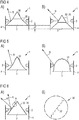
- FIG. 1A an embodiment of a ring light module 1 is shown in a schematic plan view.
- the ring light module 1 comprises a plurality of optoelectronic semiconductor components 2, in particular light emitting diodes.
- the semiconductor devices 2 are mounted in two partial arcs 26a, 26b on a tubular support 4.
- the carrier 4 preferably acts as a heat sink and heat sink for the semiconductor devices 2.
- the carrier 4 is formed by a metal core board, a printed circuit board or by overmolded lead frame.
- a reflector 3 is mounted with a reflection surface 30.
- the reflector 3 is in FIG. 1B in a schematic front view, a schematic side view and a schematic plan view shown. It has the reflector 3 has a triangular cross-section, wherein the reflection surfaces 30 may be formed straight, concave or convex. It is the reflector 3 so prismatic or approximately prismatic shaped.
- the ring light module 1 has an axis of symmetry A.
- the partial arcs 26a, 26b and the carrier 4 have as a center the axis of symmetry A, seen in plan view of a main radiation side 45 of the ring light module 1.
- the main radiation side 45 is a notional surface covering the reflector 3, the carrier 4, and the semiconductor devices 2.
- the ring light module 1 on two planes of symmetry, which are oriented perpendicular to each other and extend through the axis of symmetry A.
- the six semiconductor components 2 each in the partial circular arcs 26a, 26b face exactly one of the sides of the reflector 3.
- the reflector 3 has exactly two reflection surfaces 30.
- Figure 1C is an intensity distribution in an optical near field and in FIG. 1D shown in a far-field optical radiation emitted by the ring light module 1 radiation.
- Figure 1C It can be seen that two stripe-shaped intensity maxima occur in the near optical field.
- the far-field optical field on the other hand, there is an ellipsoid, more uniform and only a maximum intensity distribution.
- the semiconductor devices 2 are each identical in construction within the scope of manufacturing tolerances and emit radiation of the same spectral composition, in particular white light.
- differently colored semiconductor components 2 can be combined with one another and alternately follow one another, for example, semiconductor components emitting white light and semiconductor components emitting red light.
- a spectral composition of the light emitted from the semiconductor devices 2 in the sub-arc 26a may differ from the spectral composition of the radiation emitted from the semiconductor devices 2 in the sub-arc 26b. The same can apply to a luminous flux.
- the semiconductor components 2 each have a lens for beam shaping.
- the lens may be rotationally symmetrical or asymmetrical, for example oval, shaped.
- the lenses of the semiconductor components 2 may be designed differently in the partial circular arcs 26a, 26b. Alternatively, it is possible that the semiconductor devices 2 are free of lenses.
- the semiconductor components 2 may each comprise a conversion means for wavelength conversion.
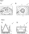
- FIG. 2A Another embodiment of the ring light module 1 is shown in FIG. 2A shown in a perspective view.
- the semiconductor devices 2 are densely arranged along a single, closed line.
- a distance between adjacent semiconductor devices 2 is small compared to the average lateral dimensions of the semiconductor devices 2.
- the ring light module 1 exactly two planes of symmetry.
- the reflector 3 has four reflection surfaces 30. Other than according to Figure 1A Thus, also end faces of the reflector 3 reflection surfaces 30 from.
- the semiconductor components 2 can be controlled individually or in groups, preferably independently of one another, so that switching between, in particular, daytime running lights, high beam and dipped headlights in a headlight for a vehicle is possible. It can be the ring light module 1 thus used in a motor vehicle headlight.
- the carrier 4 is mounted on a heat sink 8, which also forms a bottom plate of the ring light module 1.
- a heat sink 8 which also forms a bottom plate of the ring light module 1.
- side walls of the carrier 4 and an upper side of the heat sink 8 facing the reflector 3 are designed to be reflective.
- FIG. 2B a luminous flux ⁇ is plotted against an emission angle ⁇ along two orthogonal ones Directions.
- radiation takes place in only a comparatively small angular range with a half-value angle of approximately 40 °.
- the emission takes place over a large angular range of approximately 140 °.
- FIG. 3 Further embodiments of the ring light module 1 are shown as perspective views.
- the arrangement of the semiconductor components 2 corresponds in each case to in FIG. 2A shown. Deviating from this is also an arrangement of the semiconductor devices 2, as in connection with Figure 1A indicated, usable.
- the ring light module 1, as in FIG. 3A shown, has a diaphragm 9, which completely covers the semiconductor components 2, seen in plan view.
- the aperture 9 is rotationally symmetrical shaped as a disc.
- the shutter has two parts 9a, 9b which are separated from each other.
- the parts 9a, 9b are aligned parallel to a longitudinal axis of the reflector 3. It cover the parts 9a, 9b only some of the semiconductor devices 2, seen in plan view.
- the parts 9a, 9b of the diaphragm are oriented transversely to the longitudinal axis of the reflector 3.
- the reflector 3 is rotationally symmetrical and the semiconductor devices 2 are also arranged rotationally symmetrical.
- Corresponding diaphragms can also be used in all other embodiments.
- the reflector 3 is displaceably mounted relative to the semiconductor components 2.
- a displacement ⁇ h is compared to FIGS. 4A to 4B schematically drawn to each other.
- the reflector 3 has two facets 35, which form the reflection surface 30. Depending on the relative position of the semiconductor components 2 to the reflector 3, a predominant proportion of the radiation R generated by the semiconductor components 2 strikes a lower or upper one of the facets 35. In this way, an emission characteristic of the ring light module 1 can be set.
- a corresponding displacement of the reflector 3 relative to the semiconductor components 2 can also be used in all other embodiments of the ring light module 1.
- the reflection surface 30 is variable in shape.
- the reflective surface 30 has a convex shape from the viewpoint of the semiconductor devices 2.
- the semiconductor devices 2 may be located in a focal line of the reflector 3.
- the reflection surface 30 is concave.
- the emission characteristic is adjustable.
- the change in the shape of the reflection surface 30 takes place approximately via a motor or via a gas pressure or a hydraulic pressure.
- the reflection surfaces 30 can thus be shaped flexibly, similar to a rubber skin, and in particular can form steplessly different reflector profiles. This is possible for example by a thin metal foil on a substructure or by a corresponding mechanism with a spreading mechanism similar to that in a dowel.
- the reflection surface 30 is formed from a multiplicity of individually controllable facets 35, compare the detail A in FIG. 6B ,
- the reflection surface 30 is composed of the individual facets 35 and constructed similar to a Fresnel optics. Seen in cross section remains a basic shape of the reflector 3, according to FIG. 6A triangular, approximately constant. The change in the emission characteristic takes place only at the level of the facets 35, differently than in accordance with FIG. 5 ,
- An activation of the individual flanks 35 takes place, for example, via piezoelectric elements or via microelectromechanical systems, in short MEMS.
- An angle of the individual facets 35 can also be continuously adjustable in particular during operation of the annular light module 1.
- around the support 4 around the heat sink 8 is mounted with a plurality of cooling fins.
- the semiconductor components 2 are arranged rotationally symmetrically about the reflector 3 and have a comparatively small distance from one another.
- FIG Figure 8A Another embodiment of the ring light module 1 is shown in FIG Figure 8A shown.
- the Semiconductor devices 2 are arranged in several rows on the support 4 around the reflector 3 around. Due to the reflector 3, as is preferred in all other embodiments, there is no direct line of sight between opposing semiconductor components 2.
- a conversion means 7 for at least partial wavelength conversion is attached to the reflector 3. Unlike illustrated, the conversion means 7 may be limited to specific locations of the reflector 3. The conversion means 7 is arranged at a distance from the semiconductor components 2.
- FIG. 8B is the reflector 3, seen in cross section, trapezoidal shaped. Further, according to FIG. 8B the ring light module 1, a cover plate 6. On the cover plate 6, the conversion means 7 is optionally attached. Contrary to what is shown, the conversion means 7 can also be applied to a side of the cover plate 6 facing the reflector 3. Corresponding conversion means 7 and cover plates 6, as in connection with the Figures 8A and 8B can also be implemented in all other embodiments.
- two carriers 4 are arranged one above the other with the associated semiconductor components and reflectors, not shown.
- the radiation R can be emitted on both sides.
- the ring light module 1 additionally comprises a lens 5. Via the lens 5, a distribution of the radiation R is also in a direction opposite to a main emission direction of the ring light module 1 possible.
- the lens 5 acts jet shaping both refraction and reflection. Part of the radiation R does not pass through the lens 5.
Landscapes
- Engineering & Computer Science (AREA)
- General Engineering & Computer Science (AREA)
- Physics & Mathematics (AREA)
- Spectroscopy & Molecular Physics (AREA)
- Microelectronics & Electronic Packaging (AREA)
- Optics & Photonics (AREA)
- Non-Portable Lighting Devices Or Systems Thereof (AREA)
- Led Device Packages (AREA)
Claims (15)
- Module lumineux annulaire (1) comprenant- plusieurs composants semiconducteurs (2) optoélectroniques destinés à générer un rayonnement électromagnétique,- un réflecteur (3) muni d'une surface de réflexion (30), et- un support (4) sur lequel sont montés les composants semiconducteurs (2),- le réflecteur (3), vu de dessus sur un côté principal de rayonnement (45) du module lumineux annulaire (1), possédant au maximum deux plans de symétrie, une partie prédominante du rayonnement généré sortant du module lumineux annulaire (1) au niveau du côté principal de rayonnement (45),- le réflecteur (3) se rétrécissant en direction du côté principal de rayonnement (45),- les sens d'émission principaux (20) des composants semiconducteurs (2) voisins étant au moins partiellement orientés différemment les uns des autres,- les sens d'émission principaux (20) étant dirigés vers la surface de réflexion (30),
caractérisé en ce que- les composants semiconducteurs (2) sont disposés autour du réflecteur (3) en deux ou en plus de deux arcs de cercle partiel (26) et se suivant de près à l'intérieur des arcs de cercle partiel (26), et- le support (4) étant formé en symétrie de rotation et les arcs de cercle partiel (26) ainsi que le support (2) présentant le même axe de rotation (A), respectivement vus de dessus sur le côté principal de rayonnement (45). - Module lumineux annulaire (1) selon la revendication 1, avec lequel un écart moyen entre des composants semiconducteurs (2) voisins est au maximum égal à 0,75 fois un diamètre moyen des composants semiconducteurs (2), vus dans un plan perpendiculaire au sens d'émission principal (20) correspondant, l'écart moyen étant au maximum de 3,5 mm.
- Module lumineux annulaire (1) selon l'une des revendications précédentes, lequel comprend en outre au moins un obturateur (9), au moins certains des composants semiconducteurs (2) étant recouverts par l'obturateur (9), vus de dessus sur le côté principal de rayonnement (45).
- Module lumineux annulaire (1) selon la revendication précédente, avec lequel l'obturateur (9) est segmenté et ne recouvre pas tous les composants semiconducteurs (2), vus de dessus sur le côté principal de rayonnement (45).
- Module lumineux annulaire (1) selon l'une des revendications 3 ou 4, avec lequel l'obturateur est configuré absorbant ou réfléchissant que pour une plage spectrale donnée du rayonnement généré par les composants semiconducteurs (2), et a un effet transmissif pour d'autres plages spectrales.
- Module lumineux annulaire (1) selon l'une des revendications précédentes, avec lequel les composants semiconducteurs (2) ou des groupes de composants semiconducteurs (2) peuvent fonctionner électriquement indépendamment les uns des autres, une caractéristique de rayonnement dans l'espace du module lumineux annulaire (1) étant réglable par un fonctionnement sélectif d'au moins une partie des composants semiconducteurs (2).
- Module lumineux annulaire (1) selon l'une des revendications précédentes, avec lequel les composants semiconducteurs (2) sont montés mobiles par rapport à la surface de réflexion (30) et une caractéristique de rayonnement du module lumineux annulaire (1) est modifiable par une modification de la position relative entre les composants semiconducteurs (2) et la surface de réflexion (30).
- Module lumineux annulaire (1) selon l'une des revendications précédentes, avec lequel la surface de réflexion (30) est configurée sous la forme d'une optique adaptative et sa forme peut être modifiée de manière ciblée.
- Module lumineux annulaire (1) selon l'une des revendications précédentes, lequel est dépourvu d'un diffuseur qui est conçu pour une dispersion du rayonnement généré dans le module lumineux annulaire (1).
- Module lumineux annulaire (1) selon l'une des revendications précédentes, avec lequel les composants semiconducteurs (2) sont disposés en au moins deux rangées autour de la surface de réflexion (30).
- Module lumineux annulaire (1) selon l'une des revendications précédentes, les sens d'émission principaux (20) d'au moins une partie des composants semiconducteurs (2) étant dirigés vers un côté de fond (40), le côté de fond (40) étant un côté de montage du module lumineux annulaire (1) et se trouvant à l'opposé du côté principal de rayonnement (45), et avec lequel un moyen de conversion (7) destiné à une conversion de longueur d'onde partielle du rayonnement émis par les premiers composants semiconducteurs (2) est monté sur une plaque de recouvrement (6) sur le côté principal de rayonnement (45) et/ou sur la surface de réflexion (30), le moyen de conversion (7) étant disposé espacé des composants semiconducteurs (2).
- Module lumineux annulaire (1) selon l'une des revendications précédentes, avec lequel le réflecteur (4) est semi-transparent et/ou réfléchissant à sélectivité chromatique.
- Module lumineux annulaire (1) selon l'une des revendications précédentes, avec lequel la surface de réflexion (30) est constituée d'au moins deux facettes (35), les facettes (35) étant séparées les unes des autres par des arêtes.
- Module lumineux annulaire (1) selon l'une des revendications précédentes,
lequel comprend entre 8 et 32 des composants semiconducteurs (2) inclus,- un diamètre moyen de la surface de réflexion (30) étant compris entre 5 mm et 50 mm inclus,- une extension maximale de la surface de réflexion (30) dans la direction perpendiculaire au côté principal de rayonnement (45) étant comprise entre 2 mm et 50 mm inclus,- les composants semiconducteurs (2) étant conçus pour, lors d'un usage conforme à celui auquel ils sont destinés, générer respectivement un flux lumineux d'au moins 50 lm,- au moins 50 % du rayonnement généré par les composants semiconducteurs (2) étant incident sur la surface de réflexion (30),- une part d'au moins 80 % du rayonnement généré par les composants semiconducteurs (2) et incident sur la surface de réflexion (30) parvenant du côté principal de rayonnement (45) après une seule réflexion sur la surface de réflexion (30), et- la surface de réflexion (30) étant à courbure concave ou convexe. - Module lumineux annulaire (1) selon l'une des revendications précédentes,
avec lequel une lentille (5) est montée à la suite du côté principal de rayonnement (45),- la lentille (5) étant transparente au rayonnement,- un côté supérieur de lentille (50) à l'opposé du réflecteur (3) présentant un minimum central (51),- un côté inférieur de lentille (55) qui fait face au réflecteur (3) présentant un minimum circonférentiel (56),- la lentille (5) ayant un effet de mise en forme du rayonnement à la fois par réfraction et par réflexion, et- une partie du rayonnement émis par les composants semiconducteurs (2) est déviée par la lentille (5) dans une direction s'éloignant du côté supérieur de lentille (50) et cette partie du rayonnement ne passe pas à travers la lentille (5).
Applications Claiming Priority (2)
| Application Number | Priority Date | Filing Date | Title |
|---|---|---|---|
| DE102012109145.5A DE102012109145A1 (de) | 2012-09-27 | 2012-09-27 | Ringlichtmodul |
| PCT/EP2013/069266 WO2014048795A1 (fr) | 2012-09-27 | 2013-09-17 | Module d'éclairage annulaire |
Publications (2)
| Publication Number | Publication Date |
|---|---|
| EP2901072A1 EP2901072A1 (fr) | 2015-08-05 |
| EP2901072B1 true EP2901072B1 (fr) | 2017-02-15 |
Family
ID=49209369
Family Applications (1)
| Application Number | Title | Priority Date | Filing Date |
|---|---|---|---|
| EP13763065.3A Not-in-force EP2901072B1 (fr) | 2012-09-27 | 2013-09-17 | Module d'éclairage annulaire |
Country Status (4)
| Country | Link |
|---|---|
| US (1) | US9494295B2 (fr) |
| EP (1) | EP2901072B1 (fr) |
| DE (1) | DE102012109145A1 (fr) |
| WO (1) | WO2014048795A1 (fr) |
Families Citing this family (6)
| Publication number | Priority date | Publication date | Assignee | Title |
|---|---|---|---|---|
| US20170208693A1 (en) * | 2014-07-24 | 2017-07-20 | Philips Lighting Holding B.V. | Light emitting module |
| WO2017147066A1 (fr) * | 2016-02-22 | 2017-08-31 | Lumileds Llc | Distribution d'intensité lumineuse asymétrique à partir d'un luminaire |
| US10502385B2 (en) * | 2016-08-29 | 2019-12-10 | Grote Industries, Llc | Dynamic reflector system and segmented reflector of the dynamic reflector system |
| US10323813B2 (en) * | 2016-10-04 | 2019-06-18 | Michael E. Hontz | Light modules for headlights |
| US20200191344A1 (en) * | 2018-12-12 | 2020-06-18 | ETi Solid State Lighting Inc. | Led light fixture with nightlight |
| US10775018B1 (en) | 2019-09-17 | 2020-09-15 | Abl Ip Holding Llc | Direct/indirect luminaire systems and methods |
Family Cites Families (28)
| Publication number | Priority date | Publication date | Assignee | Title |
|---|---|---|---|---|
| JPH11162234A (ja) * | 1997-11-25 | 1999-06-18 | Matsushita Electric Works Ltd | 発光ダイオードを用いた光源 |
| US6561678B2 (en) * | 2001-02-05 | 2003-05-13 | James F. Loughrey | Variable focus indirect lighting fixture |
| DE10153756B4 (de) * | 2001-08-27 | 2006-05-24 | Siteco Beleuchtungstechnik Gmbh | Leuchte mit segmentiertem Innenreflektor |
| US7223005B2 (en) * | 2003-12-23 | 2007-05-29 | Lamb David J | Hybrid lightguide backlight |
| US7506985B2 (en) * | 2005-10-26 | 2009-03-24 | Hewlett-Packard Development Company, L.P. | Projection light source having multiple light emitting diodes |
| TW200728851A (en) * | 2006-01-20 | 2007-08-01 | Hon Hai Prec Ind Co Ltd | Backlight module |
| EP1826474A1 (fr) | 2006-02-22 | 2007-08-29 | Optics Lite S.r.L. | Projecteur optique avec source lumineuse à DEL radiale |
| TWI294023B (en) * | 2006-03-17 | 2008-03-01 | Ind Tech Res Inst | Reflective illumination device |
| TWI308627B (en) * | 2006-12-05 | 2009-04-11 | Ind Tech Res Inst | Illumination device of flexible lighting angle |
| EP2062295A1 (fr) * | 2006-10-19 | 2009-05-27 | Panasonic Corporation | Dispositif electroluminescent, et unite d'affichage et unite d'eclairage l'utilisant |
| WO2008146229A2 (fr) * | 2007-05-29 | 2008-12-04 | Koninklijke Philips Electronics N.V. | Système d'éclairage, luminaire et unité de rétroéclairage |
| JP4926905B2 (ja) * | 2007-09-28 | 2012-05-09 | 富士フイルム株式会社 | 面状照明装置 |
| CN101939587B (zh) * | 2008-02-05 | 2013-03-27 | 皇家飞利浦电子股份有限公司 | 具有反光电活性聚合物致动器的照明设备 |
| US20110007506A1 (en) * | 2008-04-11 | 2011-01-13 | Harison Toshiba Lighting Corp. | Lighting apparatus |
| DE102009006185A1 (de) * | 2009-01-27 | 2010-07-29 | Osram Opto Semiconductors Gmbh | Leuchtmittel |
| US20110032698A1 (en) * | 2009-08-05 | 2011-02-10 | U.R. Tech Corporation | United reflection lights with light-emitting diode |
| US7891840B1 (en) * | 2010-01-22 | 2011-02-22 | Southern Taiwan University | Polygonal radiation module having radiating members without light guiding board |
| EP2375133B1 (fr) * | 2010-04-10 | 2014-07-23 | LG Innotek Co., Ltd. | Appareil d'éclairage |
| US8360605B2 (en) * | 2010-05-09 | 2013-01-29 | Illumination Optics Inc. | LED luminaire |
| DE102010046255A1 (de) | 2010-09-22 | 2012-03-22 | Traxon Technologies Ltd. | Beleuchtungsvorrichtung |
| KR101174259B1 (ko) * | 2010-11-08 | 2012-08-14 | 엘지이노텍 주식회사 | 조명 장치 |
| EP2738445B1 (fr) * | 2010-11-08 | 2018-01-10 | LG Innotek Co., Ltd. | Appareil d'éclairage |
| US8235540B2 (en) | 2011-01-14 | 2012-08-07 | Lg Innotek Co., Ltd. | Backlight unit and display apparatus using the same |
| EP2481971A1 (fr) * | 2011-02-01 | 2012-08-01 | Tyntek Corporation | Lampe à diode électroluminescente réfléchissante |
| US8408751B2 (en) * | 2011-02-23 | 2013-04-02 | Edison Opto Corporation | Light emitting device with concave reflector surfaces |
| DE202011003261U1 (de) * | 2011-02-25 | 2011-04-28 | Hess Verwaltungs-Gmbh | Leuchteneinsatz, insbesondere für eine Bodenleuchte |
| JP5335945B2 (ja) * | 2011-12-09 | 2013-11-06 | 株式会社エンプラス | 光束制御部材および照明装置 |
| DE102012109146A1 (de) | 2012-09-27 | 2014-03-27 | Osram Opto Semiconductors Gmbh | Ringlichtmodul und Verfahren zur Herstellung eines Ringlichtmoduls |
-
2012
- 2012-09-27 DE DE102012109145.5A patent/DE102012109145A1/de not_active Withdrawn
-
2013
- 2013-09-17 EP EP13763065.3A patent/EP2901072B1/fr not_active Not-in-force
- 2013-09-17 US US14/430,898 patent/US9494295B2/en not_active Expired - Fee Related
- 2013-09-17 WO PCT/EP2013/069266 patent/WO2014048795A1/fr active Application Filing
Also Published As
| Publication number | Publication date |
|---|---|
| EP2901072A1 (fr) | 2015-08-05 |
| WO2014048795A1 (fr) | 2014-04-03 |
| US20150247616A1 (en) | 2015-09-03 |
| US9494295B2 (en) | 2016-11-15 |
| DE102012109145A1 (de) | 2014-03-27 |
Similar Documents
| Publication | Publication Date | Title |
|---|---|---|
| EP2901072B1 (fr) | Module d'éclairage annulaire | |
| DE102012202290B4 (de) | Lichtmodul für ein blendungsfreies Kraftfahrzeug-Fernlicht | |
| EP1630576B1 (fr) | Projecteur avec un faisceau lumineux prédéfini et élément optique primaire pour un projecteur | |
| DE102010056313C5 (de) | Beleuchtungseinrichtung eines Kraftfahrzeugs | |
| EP2507542B1 (fr) | Appareil d'éclairage, et dispositif d'éclairage de voie de circulation | |
| EP2643717B1 (fr) | Système optique convergent mélangeant les couleurs | |
| DE102012220570A1 (de) | Optisches element und projektionsanordnung mit einem solchen | |
| DE102013226639A1 (de) | Erzeugen eines Lichtabstrahlmusters in einem Fernfeld | |
| EP2784376A2 (fr) | Lampe de véhicule automobile pour fonctions d'éclairage dynamiques | |
| EP2827049A2 (fr) | Phare pour un phare de route anti-éblouissement | |
| EP2984397B1 (fr) | Unité d'éclairage pour projecteur de véhicule | |
| DE102011112285A1 (de) | Lichtformung mittels LED-Lichtquelle | |
| DE102017115899A1 (de) | Kraftfahrzeugleuchte und Kraftfahrzeugscheinwerfer mit einer solchen Leuchte | |
| DE102012109146A1 (de) | Ringlichtmodul und Verfahren zur Herstellung eines Ringlichtmoduls | |
| WO2007088157A1 (fr) | Lentille optique et dispositif d'éclairage avec source de lumière et lentille optique | |
| DE102016200157A1 (de) | Lichtemittierende Baugruppe und Verfahren zum Herstellen einer lichtemittierenden Baugruppe | |
| WO2016096602A1 (fr) | Dispositif luminescent doté d'un luminophore | |
| EP3477193A1 (fr) | Couvercle pour un module lumineux et module lumineux | |
| DE102015106022A1 (de) | Abstrahleinheit für eine Operationsleuchte | |
| DE102012109149A1 (de) | Ringlichtmodul und Verfahren zur Herstellung eines Ringlichtmoduls | |
| DE102010049436B4 (de) | Beleuchtungseinrichtung für ein Kraftfahrzeug | |
| DE69535403T2 (de) | Elektronische weitwinkel-beleuchtungsvorrichtung | |
| EP3045950A1 (fr) | Dispositif d'eclairage | |
| DE102018113151B4 (de) | Leuchtenmodul für eine Kraftfahrzeugleuchte | |
| AT514573B1 (de) | Lichtlenkvorrichtung und Beleuchtungseinheit mit einer solchen Lichtlenkvorrichtung |
Legal Events
| Date | Code | Title | Description |
|---|---|---|---|
| PUAI | Public reference made under article 153(3) epc to a published international application that has entered the european phase |
Free format text: ORIGINAL CODE: 0009012 |
|
| 17P | Request for examination filed |
Effective date: 20150324 |
|
| AK | Designated contracting states |
Kind code of ref document: A1 Designated state(s): AL AT BE BG CH CY CZ DE DK EE ES FI FR GB GR HR HU IE IS IT LI LT LU LV MC MK MT NL NO PL PT RO RS SE SI SK SM TR |
|
| AX | Request for extension of the european patent |
Extension state: BA ME |
|
| DAX | Request for extension of the european patent (deleted) | ||
| GRAP | Despatch of communication of intention to grant a patent |
Free format text: ORIGINAL CODE: EPIDOSNIGR1 |
|
| RIC1 | Information provided on ipc code assigned before grant |
Ipc: F21V 9/16 20060101ALN20160627BHEP Ipc: F21V 7/00 20060101ALI20160627BHEP Ipc: F21K 99/00 20160101AFI20160627BHEP Ipc: F21Y 115/10 20160101ALN20160627BHEP Ipc: F21Y 103/33 20160101ALN20160627BHEP Ipc: F21V 7/04 20060101ALI20160627BHEP |
|
| INTG | Intention to grant announced |
Effective date: 20160727 |
|
| GRAS | Grant fee paid |
Free format text: ORIGINAL CODE: EPIDOSNIGR3 |
|
| GRAA | (expected) grant |
Free format text: ORIGINAL CODE: 0009210 |
|
| AK | Designated contracting states |
Kind code of ref document: B1 Designated state(s): AL AT BE BG CH CY CZ DE DK EE ES FI FR GB GR HR HU IE IS IT LI LT LU LV MC MK MT NL NO PL PT RO RS SE SI SK SM TR |
|
| REG | Reference to a national code |
Ref country code: CH Ref legal event code: EP Ref country code: GB Ref legal event code: FG4D Free format text: NOT ENGLISH |
|
| REG | Reference to a national code |
Ref country code: IE Ref legal event code: FG4D Free format text: LANGUAGE OF EP DOCUMENT: GERMAN |
|
| REG | Reference to a national code |
Ref country code: AT Ref legal event code: REF Ref document number: 868123 Country of ref document: AT Kind code of ref document: T Effective date: 20170315 |
|
| REG | Reference to a national code |
Ref country code: DE Ref legal event code: R096 Ref document number: 502013006374 Country of ref document: DE |
|
| REG | Reference to a national code |
Ref country code: NL Ref legal event code: MP Effective date: 20170215 |
|
| REG | Reference to a national code |
Ref country code: LT Ref legal event code: MG4D |
|
| PG25 | Lapsed in a contracting state [announced via postgrant information from national office to epo] |
Ref country code: NO Free format text: LAPSE BECAUSE OF FAILURE TO SUBMIT A TRANSLATION OF THE DESCRIPTION OR TO PAY THE FEE WITHIN THE PRESCRIBED TIME-LIMIT Effective date: 20170515 Ref country code: GR Free format text: LAPSE BECAUSE OF FAILURE TO SUBMIT A TRANSLATION OF THE DESCRIPTION OR TO PAY THE FEE WITHIN THE PRESCRIBED TIME-LIMIT Effective date: 20170516 Ref country code: FI Free format text: LAPSE BECAUSE OF FAILURE TO SUBMIT A TRANSLATION OF THE DESCRIPTION OR TO PAY THE FEE WITHIN THE PRESCRIBED TIME-LIMIT Effective date: 20170215 Ref country code: LT Free format text: LAPSE BECAUSE OF FAILURE TO SUBMIT A TRANSLATION OF THE DESCRIPTION OR TO PAY THE FEE WITHIN THE PRESCRIBED TIME-LIMIT Effective date: 20170215 Ref country code: HR Free format text: LAPSE BECAUSE OF FAILURE TO SUBMIT A TRANSLATION OF THE DESCRIPTION OR TO PAY THE FEE WITHIN THE PRESCRIBED TIME-LIMIT Effective date: 20170215 |
|
| PG25 | Lapsed in a contracting state [announced via postgrant information from national office to epo] |
Ref country code: PT Free format text: LAPSE BECAUSE OF FAILURE TO SUBMIT A TRANSLATION OF THE DESCRIPTION OR TO PAY THE FEE WITHIN THE PRESCRIBED TIME-LIMIT Effective date: 20170615 Ref country code: NL Free format text: LAPSE BECAUSE OF FAILURE TO SUBMIT A TRANSLATION OF THE DESCRIPTION OR TO PAY THE FEE WITHIN THE PRESCRIBED TIME-LIMIT Effective date: 20170215 Ref country code: SE Free format text: LAPSE BECAUSE OF FAILURE TO SUBMIT A TRANSLATION OF THE DESCRIPTION OR TO PAY THE FEE WITHIN THE PRESCRIBED TIME-LIMIT Effective date: 20170215 Ref country code: ES Free format text: LAPSE BECAUSE OF FAILURE TO SUBMIT A TRANSLATION OF THE DESCRIPTION OR TO PAY THE FEE WITHIN THE PRESCRIBED TIME-LIMIT Effective date: 20170215 Ref country code: LV Free format text: LAPSE BECAUSE OF FAILURE TO SUBMIT A TRANSLATION OF THE DESCRIPTION OR TO PAY THE FEE WITHIN THE PRESCRIBED TIME-LIMIT Effective date: 20170215 Ref country code: RS Free format text: LAPSE BECAUSE OF FAILURE TO SUBMIT A TRANSLATION OF THE DESCRIPTION OR TO PAY THE FEE WITHIN THE PRESCRIBED TIME-LIMIT Effective date: 20170215 Ref country code: BG Free format text: LAPSE BECAUSE OF FAILURE TO SUBMIT A TRANSLATION OF THE DESCRIPTION OR TO PAY THE FEE WITHIN THE PRESCRIBED TIME-LIMIT Effective date: 20170515 |
|
| PG25 | Lapsed in a contracting state [announced via postgrant information from national office to epo] |
Ref country code: SK Free format text: LAPSE BECAUSE OF FAILURE TO SUBMIT A TRANSLATION OF THE DESCRIPTION OR TO PAY THE FEE WITHIN THE PRESCRIBED TIME-LIMIT Effective date: 20170215 Ref country code: IT Free format text: LAPSE BECAUSE OF FAILURE TO SUBMIT A TRANSLATION OF THE DESCRIPTION OR TO PAY THE FEE WITHIN THE PRESCRIBED TIME-LIMIT Effective date: 20170215 Ref country code: EE Free format text: LAPSE BECAUSE OF FAILURE TO SUBMIT A TRANSLATION OF THE DESCRIPTION OR TO PAY THE FEE WITHIN THE PRESCRIBED TIME-LIMIT Effective date: 20170215 Ref country code: RO Free format text: LAPSE BECAUSE OF FAILURE TO SUBMIT A TRANSLATION OF THE DESCRIPTION OR TO PAY THE FEE WITHIN THE PRESCRIBED TIME-LIMIT Effective date: 20170215 Ref country code: CZ Free format text: LAPSE BECAUSE OF FAILURE TO SUBMIT A TRANSLATION OF THE DESCRIPTION OR TO PAY THE FEE WITHIN THE PRESCRIBED TIME-LIMIT Effective date: 20170215 |
|
| REG | Reference to a national code |
Ref country code: DE Ref legal event code: R097 Ref document number: 502013006374 Country of ref document: DE |
|
| PG25 | Lapsed in a contracting state [announced via postgrant information from national office to epo] |
Ref country code: DK Free format text: LAPSE BECAUSE OF FAILURE TO SUBMIT A TRANSLATION OF THE DESCRIPTION OR TO PAY THE FEE WITHIN THE PRESCRIBED TIME-LIMIT Effective date: 20170215 Ref country code: PL Free format text: LAPSE BECAUSE OF FAILURE TO SUBMIT A TRANSLATION OF THE DESCRIPTION OR TO PAY THE FEE WITHIN THE PRESCRIBED TIME-LIMIT Effective date: 20170215 Ref country code: SM Free format text: LAPSE BECAUSE OF FAILURE TO SUBMIT A TRANSLATION OF THE DESCRIPTION OR TO PAY THE FEE WITHIN THE PRESCRIBED TIME-LIMIT Effective date: 20170215 |
|
| PLBE | No opposition filed within time limit |
Free format text: ORIGINAL CODE: 0009261 |
|
| STAA | Information on the status of an ep patent application or granted ep patent |
Free format text: STATUS: NO OPPOSITION FILED WITHIN TIME LIMIT |
|
| 26N | No opposition filed |
Effective date: 20171116 |
|
| PG25 | Lapsed in a contracting state [announced via postgrant information from national office to epo] |
Ref country code: SI Free format text: LAPSE BECAUSE OF FAILURE TO SUBMIT A TRANSLATION OF THE DESCRIPTION OR TO PAY THE FEE WITHIN THE PRESCRIBED TIME-LIMIT Effective date: 20170215 |
|
| REG | Reference to a national code |
Ref country code: CH Ref legal event code: PL |
|
| GBPC | Gb: european patent ceased through non-payment of renewal fee |
Effective date: 20170917 |
|
| PG25 | Lapsed in a contracting state [announced via postgrant information from national office to epo] |
Ref country code: MC Free format text: LAPSE BECAUSE OF FAILURE TO SUBMIT A TRANSLATION OF THE DESCRIPTION OR TO PAY THE FEE WITHIN THE PRESCRIBED TIME-LIMIT Effective date: 20170215 |
|
| REG | Reference to a national code |
Ref country code: IE Ref legal event code: MM4A |
|
| REG | Reference to a national code |
Ref country code: BE Ref legal event code: MM Effective date: 20170930 |
|
| PG25 | Lapsed in a contracting state [announced via postgrant information from national office to epo] |
Ref country code: LU Free format text: LAPSE BECAUSE OF NON-PAYMENT OF DUE FEES Effective date: 20170917 |
|
| REG | Reference to a national code |
Ref country code: FR Ref legal event code: ST Effective date: 20180531 |
|
| PG25 | Lapsed in a contracting state [announced via postgrant information from national office to epo] |
Ref country code: GB Free format text: LAPSE BECAUSE OF NON-PAYMENT OF DUE FEES Effective date: 20170917 Ref country code: IE Free format text: LAPSE BECAUSE OF NON-PAYMENT OF DUE FEES Effective date: 20170917 Ref country code: CH Free format text: LAPSE BECAUSE OF NON-PAYMENT OF DUE FEES Effective date: 20170930 Ref country code: LI Free format text: LAPSE BECAUSE OF NON-PAYMENT OF DUE FEES Effective date: 20170930 |
|
| PG25 | Lapsed in a contracting state [announced via postgrant information from national office to epo] |
Ref country code: BE Free format text: LAPSE BECAUSE OF NON-PAYMENT OF DUE FEES Effective date: 20170930 Ref country code: FR Free format text: LAPSE BECAUSE OF NON-PAYMENT OF DUE FEES Effective date: 20171002 |
|
| PG25 | Lapsed in a contracting state [announced via postgrant information from national office to epo] |
Ref country code: MT Free format text: LAPSE BECAUSE OF FAILURE TO SUBMIT A TRANSLATION OF THE DESCRIPTION OR TO PAY THE FEE WITHIN THE PRESCRIBED TIME-LIMIT Effective date: 20170215 |
|
| PGFP | Annual fee paid to national office [announced via postgrant information from national office to epo] |
Ref country code: DE Payment date: 20180920 Year of fee payment: 6 |
|
| PG25 | Lapsed in a contracting state [announced via postgrant information from national office to epo] |
Ref country code: HU Free format text: LAPSE BECAUSE OF FAILURE TO SUBMIT A TRANSLATION OF THE DESCRIPTION OR TO PAY THE FEE WITHIN THE PRESCRIBED TIME-LIMIT; INVALID AB INITIO Effective date: 20130917 |
|
| PG25 | Lapsed in a contracting state [announced via postgrant information from national office to epo] |
Ref country code: CY Free format text: LAPSE BECAUSE OF FAILURE TO SUBMIT A TRANSLATION OF THE DESCRIPTION OR TO PAY THE FEE WITHIN THE PRESCRIBED TIME-LIMIT Effective date: 20170215 |
|
| REG | Reference to a national code |
Ref country code: AT Ref legal event code: MM01 Ref document number: 868123 Country of ref document: AT Kind code of ref document: T Effective date: 20180917 |
|
| PG25 | Lapsed in a contracting state [announced via postgrant information from national office to epo] |
Ref country code: MK Free format text: LAPSE BECAUSE OF FAILURE TO SUBMIT A TRANSLATION OF THE DESCRIPTION OR TO PAY THE FEE WITHIN THE PRESCRIBED TIME-LIMIT Effective date: 20170215 |
|
| PG25 | Lapsed in a contracting state [announced via postgrant information from national office to epo] |
Ref country code: AT Free format text: LAPSE BECAUSE OF NON-PAYMENT OF DUE FEES Effective date: 20180917 |
|
| PG25 | Lapsed in a contracting state [announced via postgrant information from national office to epo] |
Ref country code: TR Free format text: LAPSE BECAUSE OF FAILURE TO SUBMIT A TRANSLATION OF THE DESCRIPTION OR TO PAY THE FEE WITHIN THE PRESCRIBED TIME-LIMIT Effective date: 20170215 |
|
| REG | Reference to a national code |
Ref country code: DE Ref legal event code: R119 Ref document number: 502013006374 Country of ref document: DE |
|
| PG25 | Lapsed in a contracting state [announced via postgrant information from national office to epo] |
Ref country code: AL Free format text: LAPSE BECAUSE OF FAILURE TO SUBMIT A TRANSLATION OF THE DESCRIPTION OR TO PAY THE FEE WITHIN THE PRESCRIBED TIME-LIMIT Effective date: 20170215 Ref country code: DE Free format text: LAPSE BECAUSE OF NON-PAYMENT OF DUE FEES Effective date: 20200401 Ref country code: IS Free format text: LAPSE BECAUSE OF FAILURE TO SUBMIT A TRANSLATION OF THE DESCRIPTION OR TO PAY THE FEE WITHIN THE PRESCRIBED TIME-LIMIT Effective date: 20170615 |