EP2900512B1 - Fahrzeug mit verbesserter hydraulischer unterstützung mit einem system zur überwachung des ölstandes im gehäuse der hydraulischen vorrichtungen - Google Patents
Fahrzeug mit verbesserter hydraulischer unterstützung mit einem system zur überwachung des ölstandes im gehäuse der hydraulischen vorrichtungen Download PDFInfo
- Publication number
- EP2900512B1 EP2900512B1 EP13766503.0A EP13766503A EP2900512B1 EP 2900512 B1 EP2900512 B1 EP 2900512B1 EP 13766503 A EP13766503 A EP 13766503A EP 2900512 B1 EP2900512 B1 EP 2900512B1
- Authority
- EP
- European Patent Office
- Prior art keywords
- casing
- hydraulic motor
- oil
- pump
- hydraulic
- Prior art date
- Legal status (The legal status is an assumption and is not a legal conclusion. Google has not performed a legal analysis and makes no representation as to the accuracy of the status listed.)
- Not-in-force
Links
Images


Classifications
-
- B—PERFORMING OPERATIONS; TRANSPORTING
- B60—VEHICLES IN GENERAL
- B60K—ARRANGEMENT OR MOUNTING OF PROPULSION UNITS OR OF TRANSMISSIONS IN VEHICLES; ARRANGEMENT OR MOUNTING OF PLURAL DIVERSE PRIME-MOVERS IN VEHICLES; AUXILIARY DRIVES FOR VEHICLES; INSTRUMENTATION OR DASHBOARDS FOR VEHICLES; ARRANGEMENTS IN CONNECTION WITH COOLING, AIR INTAKE, GAS EXHAUST OR FUEL SUPPLY OF PROPULSION UNITS IN VEHICLES
- B60K17/00—Arrangement or mounting of transmissions in vehicles
- B60K17/34—Arrangement or mounting of transmissions in vehicles for driving both front and rear wheels, e.g. four wheel drive vehicles
- B60K17/356—Arrangement or mounting of transmissions in vehicles for driving both front and rear wheels, e.g. four wheel drive vehicles having fluid or electric motor, for driving one or more wheels
-
- B—PERFORMING OPERATIONS; TRANSPORTING
- B60—VEHICLES IN GENERAL
- B60K—ARRANGEMENT OR MOUNTING OF PROPULSION UNITS OR OF TRANSMISSIONS IN VEHICLES; ARRANGEMENT OR MOUNTING OF PLURAL DIVERSE PRIME-MOVERS IN VEHICLES; AUXILIARY DRIVES FOR VEHICLES; INSTRUMENTATION OR DASHBOARDS FOR VEHICLES; ARRANGEMENTS IN CONNECTION WITH COOLING, AIR INTAKE, GAS EXHAUST OR FUEL SUPPLY OF PROPULSION UNITS IN VEHICLES
- B60K23/00—Arrangement or mounting of control devices for vehicle transmissions, or parts thereof, not otherwise provided for
- B60K23/08—Arrangement or mounting of control devices for vehicle transmissions, or parts thereof, not otherwise provided for for changing number of driven wheels, for switching from driving one axle to driving two or more axles
- B60K23/0808—Arrangement or mounting of control devices for vehicle transmissions, or parts thereof, not otherwise provided for for changing number of driven wheels, for switching from driving one axle to driving two or more axles for varying torque distribution between driven axles, e.g. by transfer clutch
-
- B—PERFORMING OPERATIONS; TRANSPORTING
- B60—VEHICLES IN GENERAL
- B60K—ARRANGEMENT OR MOUNTING OF PROPULSION UNITS OR OF TRANSMISSIONS IN VEHICLES; ARRANGEMENT OR MOUNTING OF PLURAL DIVERSE PRIME-MOVERS IN VEHICLES; AUXILIARY DRIVES FOR VEHICLES; INSTRUMENTATION OR DASHBOARDS FOR VEHICLES; ARRANGEMENTS IN CONNECTION WITH COOLING, AIR INTAKE, GAS EXHAUST OR FUEL SUPPLY OF PROPULSION UNITS IN VEHICLES
- B60K17/00—Arrangement or mounting of transmissions in vehicles
- B60K17/04—Arrangement or mounting of transmissions in vehicles characterised by arrangement, location or kind of gearing
- B60K17/10—Arrangement or mounting of transmissions in vehicles characterised by arrangement, location or kind of gearing of fluid gearing
-
- F—MECHANICAL ENGINEERING; LIGHTING; HEATING; WEAPONS; BLASTING
- F16—ENGINEERING ELEMENTS AND UNITS; GENERAL MEASURES FOR PRODUCING AND MAINTAINING EFFECTIVE FUNCTIONING OF MACHINES OR INSTALLATIONS; THERMAL INSULATION IN GENERAL
- F16H—GEARING
- F16H47/00—Combinations of mechanical gearing with fluid clutches or fluid gearing
- F16H47/02—Combinations of mechanical gearing with fluid clutches or fluid gearing the fluid gearing being of the volumetric type
-
- F—MECHANICAL ENGINEERING; LIGHTING; HEATING; WEAPONS; BLASTING
- F16—ENGINEERING ELEMENTS AND UNITS; GENERAL MEASURES FOR PRODUCING AND MAINTAINING EFFECTIVE FUNCTIONING OF MACHINES OR INSTALLATIONS; THERMAL INSULATION IN GENERAL
- F16H—GEARING
- F16H57/00—General details of gearing
- F16H57/04—Features relating to lubrication or cooling or heating
- F16H57/0434—Features relating to lubrication or cooling or heating relating to lubrication supply, e.g. pumps; Pressure control
- F16H57/0443—Features relating to lubrication or cooling or heating relating to lubrication supply, e.g. pumps; Pressure control for supply of lubricant during tilt or high acceleration, e.g. problems related to the tilt or extreme acceleration of the transmission casing and the supply of lubricant under these conditions
Definitions
- the present invention relates to vehicles equipped with a hydraulic assistance on an axle separate from the axle driven by the primary engine of the vehicle, for example the vehicles thus being able to pass from a transmission of the traction or propulsion type to an integral transmission (see JP01223030A ).
- Vehicles with hydraulic assistance that can be selectively engaged according to the training conditions desired for carrying out all or part of the wheels are known.
- Such vehicles conventionally comprise a primary engine, for example a heat engine driving a driving axle, and one or more hydraulic pumps adapted to supply one or more hydraulic motors which are typically mounted on the wheels or on a driven axle and thus realize the hydraulic assistance.
- the hydraulic pump (s) are driven by the primary engine, and are therefore located on or near the driving axle, typically in a common housing with a vehicle gearbox, and a differential if the driving axle comprises a .
- This type of configuration thus makes it possible to take a torque from the primary motor to apply it to a driven axle.
- this results in a displacement of the oil from the housing of the hydraulic pump to the crankcase of the hydraulic motor, and therefore more generally from the axle leading to the driven axle, which causes a problem of lubrication of the crankcase.
- this structure entails a risk of accumulation of the oil providing lubrication and cooling in a single housing, and therefore a risk of degradation of the apparatus in this case due to the overflow of oil which causes a heating and power losses, and in the other case because of a lack of oil.
- the present invention aims to propose a system that does not have such disadvantages.
- the invention proposes a vehicle comprising a chassis, a driving axle, a driven axle, a primary engine adapted to perform driving of the driving axle, and a hydraulic assistance system comprising a pump and a hydraulic motor. each comprising a card and connected by a hydraulic assistance circuit, said hydraulic pump being arranged close to the driving axle and the hydraulic motor being arranged close to the driven axle, characterized in that said casings of the pump and of the hydraulic motor are connected by a drainage duct ensuring an exchange of oil between said casings, said casings of the pump and the hydraulic motor being configured to define a threshold value of the oil level in the crankcase of the hydraulic motor from which the oil is discharged from the crankcase of the hydraulic motor.
- Said driven axle typically comprises a differential, the differential of the driven axle and the hydraulic motor having a common housing.
- the hydraulic pump housing is typically configured to guide the flow of oil to the feed pipe.
- the vehicle may further comprise a gearbox, and wherein said driving axle comprises a differential, the differential of the driving axle, the gearbox and the pump having a common housing.
- the vehicle further comprises a return duct connecting the casing of the hydraulic motor to the casing of the pump, the return duct comprising a return pump configured to, when said hydraulic assistance is in use, to take oil in the bottom of the casing of the hydraulic pump so as to inject it into the casing of said motor, the drainage duct being connected to the casing of the hydraulic motor so as to define the threshold value of the oil level in the casing of the hydraulic motor from which the oil is discharged from the casing of the hydraulic motor by the drainage duct, said threshold value varying according to the inclination of the vehicle.
- the return duct is then typically configured so that for vehicle inclination values between + ⁇ max and - ⁇ max with respect to a horizontal plane, the volume of oil in said hydraulic motor casing varies between values Vmin and Vmax, with Vmin nonzero and Vmax less than the internal volume of said casing.
- the drainage duct may also comprise a drainage pump adapted to ensure the circulation of the hydraulic motor housing oil towards the casing of the hydraulic pump, said drainage pump being coupled to an axle of said vehicle so that the rotation of the wheels of the vehicle causes a commissioning of the drainage pump.
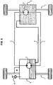
- the figure 1 is a schematic representation of an embodiment of a vehicle according to one aspect of the invention, comprising a driving axle 1 driven by a primary motor M, and a driven axle 2.
- the primary motor M is typically a heat engine.
- Each of the axles comprises for example two wheels as shown in the figure 1 other variants are of course possible.
- the driving 1 and driven 2 axles each include a hydraulic apparatus for providing user-activated hydraulic assistance.
- a hydraulic pump 3 is disposed near the driving axle 1, and a hydraulic motor 4 is disposed near the driven axle 2.
- the hydraulic devices are mounted for example on the axle in question to carry out training or to be driven by said axle.
- a hydraulic device mounted on an axle has its stator fixed to the fixed frame of the vehicle, and its rotor rotatably connected to the rotating axle considered.
- These two hydraulic devices 3 and 4 are interconnected by a hydraulic circuit C allowing the hydraulic pump 3 to supply the hydraulic motor 4 under pressure and thus allow the latter to perform the drive of the driven axle 2.
- the hydraulic devices 3 and 4 may have a reverse function, for example when braking the vehicle, the hydraulic devices being reversible.
- the hydraulic pump 3 is adapted to be driven by the primary motor M selectively, and thus to take a torque supplied by the primary motor M to the driving axle 1 to transmit it to the driven axle 2 via the motor hydraulic 4.
- Each of these hydraulic devices 3 and 4 is disposed in a housing, respectively 5 and 6 each comprising a volume of oil providing lubrication and cooling of the various components that are arranged therein.
- the casings 5 and 6 of the hydraulic pump 3 and the hydraulic motor 4 are further connected by ducts ensuring an oil exchange between said casings, so as to maintain the oil level in each of said casings in a range of values. given.
- said casings 5 and 6 as shown are connected firstly by a return duct 7 connecting an intake point 71 located in the bottom of the casing 5 of the hydraulic pump 3 with a discharge point 72 in the housing 6 of the hydraulic motor 4, and other part by a drainage pipe 8 connecting an intake point 81 located at a threshold height of the casing 6 of the hydraulic motor 4 at a discharge point 82 in the casing 5 of the hydraulic pump 3.
- the bottom of the casing 5 is advantageously configured so as to form a bowl guiding the oil towards the intake point 71.
- the return duct 7 advantageously comprises a return pump 73 associated with the hydraulic pump 3, so that the putting into service of the hydraulic pump 3 also causes the return pump 73 to be put into service, thereby effecting a transfer of the pump.
- the return pump 73 is activated jointly or prior to the commissioning of the hydraulic pump 3.
- the return pump 73 is connected to a motor M 'via a clutch 75 electrically controlled.
- the motor M ' may be the primary motor M of the vehicle, or a separate engine.
- the intake point 71 of the feeding duct is located at the bottom of the casing 5 so as to ensure that this intake point 71 is always immersed in the oil.
- the discharge in the casing 6 of the hydraulic motor 4 is typically realized by means of a booster valve block 74, configured so that the oil conveyed via the return duct 7 is distributed between the hydraulic circuit C so that 'to provide a boost, and the housing 6 of the hydraulic motor 4 to maintain a level of oil for its lubrication and cooling.
- the drainage duct 8 is adapted to define a threshold value of the oil level in the casing 6 of the hydraulic motor 4 from which the oil is conveyed to the casing 5 of the hydraulic pump 3, said threshold value varying according to the inclination of the vehicle.
- the inlet point 81 of the drainage duct 8 is disposed at a predetermined height of the casing 6 of the hydraulic motor, so that when the oil in this casing 6 reaches this point of admission 81, it is transferred to the casing 5 of the hydraulic pump 3. It is understood that the inclination of the vehicle affects the volume of oil which can be stored in the housing 6 of the hydraulic motor 4. Indeed, for a given volume of oil V, the point of admission 81 will or will not be reached depending on its location and the inclination of the vehicle.
- a maximum inclination value for a given vehicle is considered in order to position the intake point 81 and thus to ensure that the volume of oil in the casing 6 of the hydraulic motor 4 is between a threshold value lower Vinf and an upper threshold value Vsup, these two threshold values Vinf and Vsup being calibrated so as to ensure optimum lubrication and cooling of the various components arranged in the casing 6, and in particular so as to prevent this casing 6 from being completely filled of oil which would cause losses and a significant heating.
- the drainage duct 8 is advantageously a passive duct, that is to say it is a duct that does not require the operation of appliances to operate, and the transfer of oil through this duct drainage 8 can therefore be performed even when the hydraulic assistance is not put into operation.
- the drainage duct 8 may comprise a drainage pump 83 adapted to be put into operation with the hydraulic motor 4, or to be driven by the rotation of the driven axle 2.
- the pump 83 is connected to the axle 2 by means of bevel gears 84, so that the rotation of the axle 2 causes the operation of the drainage pump 83.
- Such a pump makes it possible to ensure the circulation of the oil of the casing 6 towards the casing 5, the circulation in the opposite direction being ensured in particular by the return pump 73.
- the fact of driving the pump by the rotation of the driven axle 2 ensures the flow of oil even when the hydraulic devices are not in use.
- the drainage pump 83 is then advantageously configured so as to be able to operate without load.
- the vehicle structure thus described adapts to many axle and transmission configurations.
- the figure 1 presents an example of a structure comprising a single driving axle and a single driven axle, but that this structure also applies to a vehicle having a larger number of axles equipped with components for which it is necessary to provide lubrication and a cooling.
- the driving axles 1 and 2 thus each advantageously comprise a differential which is coupled to the hydraulic apparatus 3 or 4 associated with the axle concerned, said differentials then typically being arranged in the same casing as the associated hydraulic apparatus.
- the driving axle 1 is moreover typically associated with a gearbox interposed between the primary motor M and the driving axle 1 or, if appropriate, the associated differential. This gearbox is then typically arranged in the same casing as the associated hydraulic device, in this case the casing 5 of the hydraulic pump 3.
- the casing 5 of the pump 3 and / or the casing 6 of the engine 4 typically comprise a means of checking the oil level.
- oil level control means can be used. It is thus possible to arrange transparent sections in the casings 5 and / or 6 so that an observer outside the casing can easily see the oil level. Alternatively, can be arranged openings in the casings 5 and / or 6 which are closed by plugs, that the user can remove to control the oil level either directly visually, or by means of a gauge.
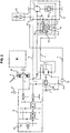
- the figure 2 presents a more detailed view of the various components that can be arranged in the casings 5 and 6, as well as associated hydraulic circuits.
- a clutch 91 selectively couples the primary motor M to the gearbox 92.
- the driving differential 93 is mounted on the driving axle 1, and divides it into two half-axles that can rotate at different speeds.
- the driving differential 93 is also connected to an output shaft of the gearbox 92 which applies to it an input torque.
- gearbox 92, the driving differential 93 and the hydraulic pump 3 are all arranged in the same casing 5, while the hydraulic motor 4 and the driven differential 94 are arranged in the same casing 6.
- Each of the housings 5 and 6 further comprises a breather, respectively 51 and 61, for evacuating the oil vapors in the housings, and calibrated to limit the pressure differentials that may arise in particular from overheating in operation, and differences due to temperature variations for example in the context of a daily cycle of the vehicle.
- the breather 61 of the casing 6 of the hydraulic motor 4 is advantageously calibrated so as to maintain a sufficient pressure in said casing 6 so that the oil is returned to the casing 5 via the drainage duct 8 when the oil level is sufficient, by a pump effect due to the overpressure in the housing 6.
- a breather 61 calibrated more feebly for the inlet than for the outlet of the casing 6, or a breather 61 allowing only the entry of air into the casing 6.
- a breather 61 may be an alternative to adding a pump to the drainage duct 8.
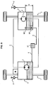
- the Figures 3, 4 and 5 present the effect of the inclination of the vehicle on the oil exchanges between the casings 5 and 6.
- These figures show in a simplified manner a vehicle chassis comprising a driving axle 1 and a driven axle 2, as well as the casings 5 and 6 as already presented above, for example with a structure as presented on the figure 2 .
- a horizontal plane XX relative to which the vehicle is calibrated to be able to tilt an angle ⁇ max .
- the figure 3 represents the vehicle traveling on a horizontal surface.
- the inlet 81 of the drainage duct 8 is advantageously positioned so that the volume of oil in the casing 6 is optimal; it is represented in this figure by the optimal shaded area V.
- the volume of oil in the casing 5 is advantageously also equal to its optimum value V5opt.
- the figure 4 represents the vehicle on a plane inclined forwards by an angle ⁇ max, corresponding for example to the maximum inclination for which the vehicle is adapted to roll. It is clearly seen in this figure that the volume of oil in the housing 6 decreases due to the inclination of the housing 6 to a value Vmin, the volume of oil in the housing 5 is then at its maximum value V5max .
- the figure 5 represents the vehicle on a plane inclined towards the rear of the angle ⁇ max. It is clearly seen in this figure that the volume of oil in the casing 6 increases due to the inclination of the casing 6 to reach its maximum value Vmax, the volume of oil in the casing 5 then being at its minimum value V5min.
- the volume of oil in the casing 6 will therefore be between Vmin and Vmax according to the conditions of use, these two values being advantageously centered on the value Voptimal corresponding to the optimum volume of oil in the casing 6 to ensure the lubrication and cooling of the components it contains.
- this structure prevents all the oil is accumulated in the casing 6 to the detriment of the casing 5, and the casing 6 is completely filled with oil.
- the ducts providing an oil exchange between the two casings 5 and 6 thus make it possible to ensure optimized lubrication and cooling of a plurality of vehicle components.
- the figure 6 presents another embodiment of a vehicle according to one aspect of the invention.
- the casing 6 of the hydraulic motor 4 is a sealed casing filled with oil.
- the casing 5 of the pump 3 is an open casing comprising an air exchanger, here a breather 51 as already described above.
- the drainage duct 8 connects the bottom of the casing 5 of the pump 3 to the top of the casing 6 of the hydraulic motor 4.
- This embodiment makes it possible to ensure that the casing 6 of the hydraulic motor 4 is in no case emptied of oil. We can then simply control the volume of oil in the casing 5 of the pump 3. This embodiment is easier to implement and requires little additional components. It also makes it possible to have different altitudes between the casing 5 of the pump 3 and the casing 6 of the hydraulic motor 4.
- the figure 7 presents another embodiment of a vehicle according to one aspect of the invention.
- the casing 6 of the hydraulic motor 4 is a sealed casing in which is inserted an initial volume of oil, the remaining volume of the casing 6 of the hydraulic motor 4 being filled with air defining a quantity of air .
- the casing 5 of the pump 3 is in turn an open casing comprising an air exchanger, here a breather 51.
- the drainage duct 8 connects the bottom of the casing 5 of the pump 3 to the bottom of the casing 6 of the hydraulic motor 4.
- the orifices connecting the drainage duct 8 to each of the casings 5 and 6 are thus permanently immersed in the oil.
- the housing 6 of the hydraulic motor 4 being a sealed housing, the amount of air contained therein remains constant. Therefore, this amount of air serves as a return means for the oil in the casing 6 of the hydraulic motor 4. If the amount of oil in the housing 6 of the hydraulic motor 4 increases, the air pressure increases, which exerts a thrust force so as to evacuate the oil to bring it back to its original volume. Conversely, if the amount of oil in the casing 6 of the hydraulic motor 4 decreases; the air pressure decreases which causes a suction of oil in the casing 6 of the hydraulic motor 4 to bring it back to its initial volume.
- the threshold value of the oil level in the casing 6 of the hydraulic motor 4 from which the oil is discharged from the casing 6 of the engine Hydraulic 4 through the drainage duct 8 is thus defined by the amount of air in the casing 6 of the hydraulic motor 4.
- the temperature variation within the casing 6 of the hydraulic motor 4 causes variations in the volume of the quantity of air introduced into the casing 6 of the hydraulic motor 4, these variations being calculated so that the variation of the oil level in the crankcase 6 of the hydraulic motor 4 has no influence on the hydraulic motor 4.
- This embodiment is advantageous for the very small number of parts that it requires. Due to the return effect of the amount of air, it also allows for different altitudes between the casing 5 of the pump 3 and the casing 6 of the hydraulic motor 4. Finally, the drag of this embodiment is lower compared to the embodiments in which the casing 6 of the hydraulic motor 4 is full.
- the figure 8 presents another embodiment of a vehicle according to one aspect of the invention.
- Each of the upsets 852 and 862 comprises a non-return valve configured to pass only the drainage duct 8 to each of said casings 5 and 6, thus allowing the oil supply of each of the casings 5 and 6 through the drain duct.
- the inlet 851 in the casing 5 of the pump 3 is provided with a valve equipped with a float 853 configured to open said valve when the oil level in the casing of the pump 3 is beyond a second threshold value.
- the valve allows the oil to pass from the casing 5 of the pump 3 to the drainage duct 8 only when the oil level in the casing 5 of the pump 3 is beyond this second threshold value which triggers the opening of the valve by the float 853.
- the inlet 861 in the casing 6 of the hydraulic motor 4 is also provided with a valve equipped with a float 863 defining the threshold value of the oil level in the casing 6 of the hydraulic motor 4 from which the oil is removed from the housing 6 of the hydraulic motor 4 by the drainage duct 8.
- the float 863 is configured to open said intake valve 861 when the oil level in the casing 6 of the hydraulic motor 4 is beyond said threshold value.
- This particular embodiment has several advantages. Due to the system with floats driving the transfer of oil between the housings, it does not require application of pressure in the housings that can be opened, for example by means of a breather. Such an embodiment also has good stability with temperature. Finally, the drag is low compared to the embodiments in which the casing 6 of the hydraulic motor 4 is full.
- the figure 9 presents another embodiment of a vehicle according to the invention.
- the oil thus taken from the casing 6 of the hydraulic motor 4 is conveyed by the drainage duct 8 into the drainage chamber 87 and then into the casing 5 of the pump 3.
- the float 863 is configured so that the drainage chamber 87 is kept filled with oil.
- the inlet valve 861 and the float 863 are advantageously arranged in a portion of the casing 6 of the hydraulic motor 4 in which the oil is undisturbed, for example a portion of the casing 6 partially surrounded by a partition or a wall, so that swirls in the oil do not disturb the movement of the float 863.
- the casing 5 of the pump 3 is common with the casing of the gearbox of the vehicle.
- the casing 6 of the hydraulic motor 4 is sized to contain an oil volume defined to be less than or equal to the variation of the possible oil level in the casing 5 of the pump 3.
- the casing 5 of the pump 3 is for example dimensioned so as to have a volume of the order of 10 times or more than that of the casing 6 of the hydraulic motor 4. For example, if it is considered that the casing 5 of the pump 3 is sized to have a volume of oil equal to 2 liters to 0.1 liters, then the housing 6 of the hydraulic motor 4 is sized to contain a maximum volume of oil equal to 0.1 liter.
- This embodiment provides a substantially constant oil level in the casing 5 of the pump 3 and the gearbox of the vehicle, while maintaining a simple structure and having a low drag.
- the two casings 5 and 6 can thus be kept bubbling.
- the different embodiments presented thus make it possible to carry out a control of the oil level between two crankcases, by providing an oil evacuation from the crankcase to the pump crankcase when the oil level in the crankcase reaches a threshold value. , thus ensuring a balance of oil level between the crankcase and the crankcase pump since the oil tends to accumulate in the crankcase and not in the pump housing due to the action of the pump.
Landscapes
- Engineering & Computer Science (AREA)
- Chemical & Material Sciences (AREA)
- Combustion & Propulsion (AREA)
- Transportation (AREA)
- Mechanical Engineering (AREA)
- General Details Of Gearings (AREA)
- Motor Power Transmission Devices (AREA)
Claims (12)
- Fahrzeug mit einem Fahrgestell, einer Antriebsachse (1), einer angetriebenen Achse (2), einem Primärmotor (M), der geeignet ist, einen Antrieb der Antriebsachse (1) durchzuführen, und einem hydraulischen Unterstützungssystem, das ein Pumpe (3) und einen Hydraulikmotor (4) umfasst, die jeweils ein Gehäuse (5, 6) umfassen und durch einen hydraulischen Unterstützungskreis (C) verbunden sind,
wobei die Hydraulikpumpe (3) in der Nähe der Antriebsachse (1) angeordnet ist und der Hydraulikmotor in der Nähe der angetriebenen Achse (2) angeordnet ist,
dadurch gekennzeichnet, dass die Gehäuse (5, 6) der Pumpe (3) und des Hydraulikmotors (4) durch ein Drainagerohr (8) verbunden sind, das einen Ölaustausch zwischen den Gehäusen (5, 6) gewährleistet, wobei die Gehäuse (5, 6) der Pumpe (3) und des Hydraulikmotors (4) derart konfiguriert sind, dass ein Grenzwert des Ölstands im Gehäuse (6) des Hydraulikmotors (4) festgelegt ist, ab dem das Öl aus dem Gehäuse (6) des Hydraulikmotors (4) abgeleitet wird. - Fahrzeug nach Anspruch 1, wobei die angetriebene Achse (2) ein Differential (94) umfasst, wobei das Differential (94) der angetriebenen Achse (2) und der Hydraulikmotor (4) ein gemeinsames Gehäuse (6) haben.
- Fahrzeug nach einem der Ansprüche 1 bis 2, wobei das Gehäuse (5) der Hydraulikpumpe (3) derart konfiguriert ist, dass der Ölstrom zur Füllleitung (7) geleitet wird.
- Fahrzeug nach einem der Ansprüche 1 bis 3, die ferner ein Getriebe (92) umfasst, und wobei die Antriebsachse (1) ein Differential (93) umfasst, wobei das Differential (93) der Antriebsachse (1), das Getriebe (92) und die Pumpe (3) ein gemeinsames Gehäuse (5) haben.
- Fahrzeug nach einem der Ansprüche 1 bis 4, wobei:- das Gehäuse (6) des Hydraulikmotors (4) ein dichtes Gehäuse ist, in das ein anfängliches Ölvolumen eingefüllt wird, wobei das restliche Volumen des Gehäuses (6) mit Luft gefüllt ist, das eine Luftmenge definiert,- das Gehäuse (5) der Pumpe (3) ein offenes Gehäuse ist, das einen Luftaustauscher umfasst,wobei die Drainageleitung (8), die den Boden des Gehäuses (5) der Pumpe (3) mit dem Boden des Gehäuses (6) des Hydraulikmotors (4) verbindet, so dass die Öffnungen, welche die Drainageleitung (8) mit den Gehäusen (5, 6) verbinden, in das Öl eingetaucht sind, wobei der Grenzwert des Ölstands in dem Gehäuse (6) des Hydraulikmotors (4), ab dem das Öl aus dem Gehäuse (6) des Hydraulikmotors (4) durch die Drainageleitung (8) abgeleitet wird, somit durch die Luftmenge in dem Gehäuse (6) des Hydraulikmotors (4) definiert ist.
- Fahrzeug nach einem der Ansprüche 1 bis 4, wobei:- das Gehäuse (6) des Hydraulikmotors (4) ein dichtes, mit Öl gefülltes Gehäuse ist,- das Gehäuse (5) der Pumpe (3) ein offenes Gehäuse ist, das einen Luftaustauscher umfasst,wobei die Drainageleitung (8) den Boden des Gehäuses (5) der Pumpe (3) mit der Spitze des Gehäuses (6) des Hydraulikmotors (4) verbindet, wobei der Grenzwert des Ölstands in dem Gehäuse (6) des Hydraulikmotors (4), ab dem das Öl aus dem Gehäuse (6) des Hydraulikmotors (4) durch die Drainageleitung (8) abgeleitet wird, somit der Ölstand ist, für welchen das Gehäuse (6) des Hydraulikmotors (4) mit Öl gefüllt ist.
- Fahrzeug nach einem der Ansprüche 1 bis 4, wobei das Drainagerohr (8) umfasst:- einen Einlass (851) im Gehäuse (5) der Pumpe (3),- einen Auslass (852) im Gehäuse (5) der Pumpe (3),- einen Einlass (861) im Gehäuse (6) des Hydraulikmotors (4),- einen Auslass (862) im Gehäuse (6) des Hydraulikmotors (4),wobei jeder Auslässe (852, 862) ein Sperrventil umfasst, das konfiguriert ist, um nur von der Drainageleitung (8) zu jedem der Gehäuse (5, 6) durchgängig zu sein, und
wobei der Einlass (851) im Gehäuse (5) der Pumpe (3) mit einem Ventil ausgestattet ist, das mit einem Schwimmer (853) versehen ist, der konfiguriert ist, um das Ventil zu öffnen, wenn der Ölstand im Gehäuse der Pumpe (3) jenseits eines zweiten Grenzwerts liegt,
wobei der Einlass (861) im Gehäuse (6) des Hydraulikmotors (4) mit einem Ventil ausgestattet ist, das mit einem Schwimmer (863) versehen ist, der den Grenzwert des Ölstands im Gehäuse (6) des Hydraulikmotors (4) definiert, ab dem das Öl aus dem Gehäuse (6) des Hydraulikmotors (4) durch die Drainageleitung (8) abgeleitet wird und konfiguriert ist, um das Ventil zu öffnen, wenn der Ölstand im Gehäuse (6) des Hydraulikmotors (4) jenseits des Grenzwerts liegt. - Fahrzeug nach Anspruch 4, wobei- die Drainageleitung (8) eine Drainagekammer (87) umfasst,- die Drainageleitung (8) mit der Drainagekammer (87) mittels eines Ventils verbunden ist, das mit einem Schwimmer versehen ist, welcher den Grenzwert des Ölstandes im Gehäuse (6) des Hydraulikmotors (4) definiert, ab dem das Öl aus dem Gehäuse (6) des Hydraulikmotors (4) durch die Drainageleitung (8) abgeleitet wird und konfiguriert ist, um das Ventil zu öffnen, wenn der Ölstand im Gehäuse des Hydraulikmotors (43) jenseits des Grenzwerts liegt,wobei der Schwimmer derart konfiguriert ist, dass die Drainagekammer mit Öl gefüllt bleibt,
wobei das Gehäuse (6) des Hydraulikmotors (4) so bemessen ist, dass es ein Ölvolumen zwischen 0 und V1 enthält,
wobei das gemeinsame Gehäuse (5) des Getriebes (92) und der Pumpe (3) so bemessen ist, dass es ein Ölvolumen V2 mit einer Toleranz von zirka T2 mit T2 ≥ V1 enthält. - Fahrzeug nach Anspruch 8, wobei das Gehäuse (6) des Hydraulikmotors (4) einen Entlüfter (61) umfasst, wobei der Entlüfter (61) umfasst- einen Lufteinlass, der derart konfiguriert ist, um auf einer Höhe zu sein, die höher als die des Gehäuses (6) des Hydraulikmotors (4) ist,- eine Verbindung mit dem Gehäuse (6) des Hydraulikmotors (4), wobei die Verbindung in einer Höhe H des Gehäuses (6) des Hydraulikmotors (4) positioniert ist und einen maximalen Ölstand im Gehäuse (6) des Hydraulikmotors (4) definiert.
- Fahrzeug nach einem der Ansprüche 1 bis 4, das ferner eine Rücklaufleitung (7) umfasst, die das Gehäuse (6) des Hydraulikmotors (4) mit dem Gehäuse (5) der Pumpe (3) verbindet,
wobei die Rücklaufleitung (7) eine Rückförderpumpe (73) umfasst, die konfiguriert ist, um, wenn die Hydraulikunterstützung im Betrieb ist, Öl vom Boden des Gehäuses (5) der Hydraulikpumpe (3) derart zu entnehmen, dass es in das Gehäuse (6) des Motors (4) geleitet wird,
wobei die Drainageleitung (8) mit dem Gehäuse (6) des Hydraulikmotors (4) derart verbunden ist, dass der Grenzwert des Ölstands im Gehäuse (6) des Hydraulikmotors (4) definiert wird, ab dem das Öl aus dem Gehäuse (6) des Hydraulikmotors (4) durch die Drainageleitung (8) abgeleitet wird, wobei der Grenzwert in Abhängigkeit von der Neigung des Fahrzeugs schwankt. - Fahrzeug nach Anspruch 10, wobei die Rücklaufleitung derart konfiguriert ist, dass für Neigungswerte des Fahrzeugs zwischen +θmax und -θmax in Bezug zu einer horizontalen Ebene das Ölvolumen im Gehäuse (6) des Hydraulikmotors (4) zwischen Werten Vmin und Vmax mit Vmin ungleich Null und Vmax kleiner als das Innenvolumen des Gehäuses (6) schwankt.
- Fahrzeug nach einem der Ansprüche 10 oder 11, wobei die Drainageleitung (8) eine Drainagepumpe (83) umfasst, die geeignet ist, die Zirkulation von Öl aus dem Gehäuse (6) des Hydraulikmotors (4) zum Gehäuse (5) der Hydraulikpumpe (3) zu gewährleisten, wobei die Drainagepumpe (83) mit einer Achse des Fahrzeugs derart gekoppelt ist, dass die Drehung der Räder des Fahrzeugs zu einer Inbetriebnahme der Drainagepumpe (83) führt.
Applications Claiming Priority (2)
| Application Number | Priority Date | Filing Date | Title |
|---|---|---|---|
| FR1259198A FR2996177B1 (fr) | 2012-09-28 | 2012-09-28 | Vehicule muni d'une assistance hydraulique amelioree integrant un systeme de gestion des niveaux d'huile dans les carters des appareils hydrauliques |
| PCT/EP2013/069517 WO2014048839A1 (fr) | 2012-09-28 | 2013-09-19 | Véhicule muni d'une assistance hydraulique améliorée intégrant un système de gestion des niveaux d'huile dans les carters des appareils hydrauliques |
Publications (2)
| Publication Number | Publication Date |
|---|---|
| EP2900512A1 EP2900512A1 (de) | 2015-08-05 |
| EP2900512B1 true EP2900512B1 (de) | 2016-06-08 |
Family
ID=47505069
Family Applications (1)
| Application Number | Title | Priority Date | Filing Date |
|---|---|---|---|
| EP13766503.0A Not-in-force EP2900512B1 (de) | 2012-09-28 | 2013-09-19 | Fahrzeug mit verbesserter hydraulischer unterstützung mit einem system zur überwachung des ölstandes im gehäuse der hydraulischen vorrichtungen |
Country Status (3)
| Country | Link |
|---|---|
| EP (1) | EP2900512B1 (de) |
| FR (1) | FR2996177B1 (de) |
| WO (1) | WO2014048839A1 (de) |
Families Citing this family (3)
| Publication number | Priority date | Publication date | Assignee | Title |
|---|---|---|---|---|
| GB201611779D0 (en) * | 2016-07-06 | 2016-08-17 | Agco Int Gmbh | Utility vehicle lubrication and cooling |
| FR3096935B1 (fr) * | 2019-06-04 | 2021-06-18 | Poclain Hydraulics Ind | Procédé d’ajout d’une machine hydraulique à un engin comprenant une transmission primaire |
| FR3115572B1 (fr) * | 2020-10-23 | 2023-01-27 | Poclain Hydraulics Ind | Circuit d’assistance hydraulique amélioré |
Family Cites Families (10)
| Publication number | Priority date | Publication date | Assignee | Title |
|---|---|---|---|---|
| US3140041A (en) * | 1961-01-09 | 1964-07-07 | Kramer Trenton Co | Means for controlling lubrication of hermetic compressors |
| DE1680157A1 (de) * | 1968-02-21 | 1971-12-23 | Linde Ag | Kraftfahrzeug |
| FR2358615A1 (fr) * | 1976-07-16 | 1978-02-10 | Snecma | Systeme de recuperation d'huile |
| DE3308295A1 (de) * | 1983-03-09 | 1984-09-13 | Zahnradfabrik Friedrichshafen Ag, 7990 Friedrichshafen | Fahrzeug |
| JPH01223030A (ja) * | 1988-03-01 | 1989-09-06 | Koyo Seiko Co Ltd | 4輪駆動車 |
| GB2322421B (en) * | 1997-02-19 | 2001-02-07 | Delphi France Automotive Sys | Automatic transmission |
| US6241038B1 (en) * | 1998-11-05 | 2001-06-05 | New Holland North America, Inc. | Remote drop box lubrication circuit for tractors |
| AT4967U1 (de) * | 2000-10-19 | 2002-01-25 | Zahnradfabrik Friedrichshafen | Getriebeeinheit mit verschieden hohen ölspiegeln |
| JP2006315655A (ja) * | 2005-04-12 | 2006-11-24 | Kanzaki Kokyukoki Mfg Co Ltd | 油圧駆動式作業車両及び車軸駆動装置 |
| JP2009108898A (ja) * | 2007-10-29 | 2009-05-21 | Toyota Motor Corp | オイルの潤滑構造 |
-
2012
- 2012-09-28 FR FR1259198A patent/FR2996177B1/fr not_active Expired - Fee Related
-
2013
- 2013-09-19 EP EP13766503.0A patent/EP2900512B1/de not_active Not-in-force
- 2013-09-19 WO PCT/EP2013/069517 patent/WO2014048839A1/fr not_active Ceased
Non-Patent Citations (1)
| Title |
|---|
| None * |
Also Published As
| Publication number | Publication date |
|---|---|
| EP2900512A1 (de) | 2015-08-05 |
| FR2996177B1 (fr) | 2014-10-03 |
| WO2014048839A1 (fr) | 2014-04-03 |
| FR2996177A1 (fr) | 2014-04-04 |
Similar Documents
| Publication | Publication Date | Title |
|---|---|---|
| EP2943702B1 (de) | Anordnung zum schmieren zweier nebeneinander liegender vertikal gestufter räderwerke | |
| EP3189998B1 (de) | Hydraulische vorrichtung, die einen niedrigdruck-wahlschalter umfasst und fahrzeug, das eine solche vorrichtung umfasst | |
| EP3126175B1 (de) | Hydraulisches unterstützungssystem | |
| EP2900512B1 (de) | Fahrzeug mit verbesserter hydraulischer unterstützung mit einem system zur überwachung des ölstandes im gehäuse der hydraulischen vorrichtungen | |
| FR2519698A1 (fr) | Ensemble moteur suspendu pour vehicule a deux roues | |
| EP3002484A1 (de) | Ölverteilungsvorrichtung mit rückschlagventil | |
| EP2817164B1 (de) | Kompaktes hydromodul für hydraulisches hybridfahrzeug | |
| FR2458419A1 (fr) | Perfectionnement a une transmission automatique a essieu transversal | |
| FR2982003A1 (fr) | Installation de transmission de couple comportant une boite de vitesses dans laquelle les arbres primaire et secondaire sont agences au-dessus du liquide lubrifiant | |
| EP3728906B1 (de) | Pumpensaugkreis | |
| FR2697883A1 (fr) | Ensemble hydromécanique d'entraînement. | |
| FR2887499A1 (fr) | Systeme d'entrainement d'un vehicule automobile | |
| EP2817165B1 (de) | Konpaktes hydraulikmodul für hybrides hydraulisches fahrzeug | |
| EP4522890A1 (de) | Untersetzungsgetriebe eines hybriden kraftwerks | |
| FR2837140A1 (fr) | Essieu moteur comportant un moteur de roulage et un differentiel | |
| EP3824205B1 (de) | Schaltung für hydraulische unterstützung mit verbesserten zuführmitteln | |
| EP4453449A1 (de) | Vorrichtung und verfahren zur steuerung eines elektrohydraulischen getriebes | |
| FR3019610A1 (fr) | Systeme d'assistance hydraulique pour vehicule | |
| FR3035829A1 (fr) | Systeme d'assistance hydraulique pour engins motorises a circuit ouvert | |
| EP2817166B1 (de) | Konpaktes hydraulikmodul für hybrides hydraulisches fahrzeug | |
| FR2830290A1 (fr) | Pompe double a engrenages, et installation utilisant une telle pompe | |
| FR3115572A1 (fr) | Circuit d’assistance hydraulique amélioré | |
| FR3044977A1 (fr) | Vehicule automobile a quatre roues motrices et a propulsion hybride comprenant un differentiel dote d'un module hydraulique | |
| FR3010006A1 (fr) | Vehicule a assistance hydraulique comprenant une structure amelioree de differentiel sur l'essieu mene | |
| WO2019185585A1 (fr) | Véhicule équipé d'un système hydraulique d'assistance à l'entraînement et système hydraulique d'assistance prévu à cette fin |
Legal Events
| Date | Code | Title | Description |
|---|---|---|---|
| PUAI | Public reference made under article 153(3) epc to a published international application that has entered the european phase |
Free format text: ORIGINAL CODE: 0009012 |
|
| 17P | Request for examination filed |
Effective date: 20150427 |
|
| AK | Designated contracting states |
Kind code of ref document: A1 Designated state(s): AL AT BE BG CH CY CZ DE DK EE ES FI FR GB GR HR HU IE IS IT LI LT LU LV MC MK MT NL NO PL PT RO RS SE SI SK SM TR |
|
| AX | Request for extension of the european patent |
Extension state: BA ME |
|
| DAX | Request for extension of the european patent (deleted) | ||
| GRAP | Despatch of communication of intention to grant a patent |
Free format text: ORIGINAL CODE: EPIDOSNIGR1 |
|
| RIC1 | Information provided on ipc code assigned before grant |
Ipc: B60K 17/356 20060101AFI20160127BHEP Ipc: F16H 57/04 20060101ALI20160127BHEP Ipc: B60K 23/08 20060101ALI20160127BHEP |
|
| INTG | Intention to grant announced |
Effective date: 20160222 |
|
| GRAS | Grant fee paid |
Free format text: ORIGINAL CODE: EPIDOSNIGR3 |
|
| GRAA | (expected) grant |
Free format text: ORIGINAL CODE: 0009210 |
|
| AK | Designated contracting states |
Kind code of ref document: B1 Designated state(s): AL AT BE BG CH CY CZ DE DK EE ES FI FR GB GR HR HU IE IS IT LI LT LU LV MC MK MT NL NO PL PT RO RS SE SI SK SM TR |
|
| REG | Reference to a national code |
Ref country code: GB Ref legal event code: FG4D Free format text: NOT ENGLISH |
|
| REG | Reference to a national code |
Ref country code: CH Ref legal event code: EP |
|
| REG | Reference to a national code |
Ref country code: IE Ref legal event code: FG4D Free format text: LANGUAGE OF EP DOCUMENT: FRENCH |
|
| REG | Reference to a national code |
Ref country code: AT Ref legal event code: REF Ref document number: 804953 Country of ref document: AT Kind code of ref document: T Effective date: 20160715 |
|
| REG | Reference to a national code |
Ref country code: DE Ref legal event code: R096 Ref document number: 602013008479 Country of ref document: DE |
|
| REG | Reference to a national code |
Ref country code: FR Ref legal event code: PLFP Year of fee payment: 4 |
|
| REG | Reference to a national code |
Ref country code: LT Ref legal event code: MG4D |
|
| REG | Reference to a national code |
Ref country code: NL Ref legal event code: MP Effective date: 20160608 |
|
| PG25 | Lapsed in a contracting state [announced via postgrant information from national office to epo] |
Ref country code: FI Free format text: LAPSE BECAUSE OF FAILURE TO SUBMIT A TRANSLATION OF THE DESCRIPTION OR TO PAY THE FEE WITHIN THE PRESCRIBED TIME-LIMIT Effective date: 20160608 Ref country code: LT Free format text: LAPSE BECAUSE OF FAILURE TO SUBMIT A TRANSLATION OF THE DESCRIPTION OR TO PAY THE FEE WITHIN THE PRESCRIBED TIME-LIMIT Effective date: 20160608 Ref country code: NO Free format text: LAPSE BECAUSE OF FAILURE TO SUBMIT A TRANSLATION OF THE DESCRIPTION OR TO PAY THE FEE WITHIN THE PRESCRIBED TIME-LIMIT Effective date: 20160908 |
|
| REG | Reference to a national code |
Ref country code: AT Ref legal event code: MK05 Ref document number: 804953 Country of ref document: AT Kind code of ref document: T Effective date: 20160608 |
|
| PG25 | Lapsed in a contracting state [announced via postgrant information from national office to epo] |
Ref country code: SE Free format text: LAPSE BECAUSE OF FAILURE TO SUBMIT A TRANSLATION OF THE DESCRIPTION OR TO PAY THE FEE WITHIN THE PRESCRIBED TIME-LIMIT Effective date: 20160608 Ref country code: RS Free format text: LAPSE BECAUSE OF FAILURE TO SUBMIT A TRANSLATION OF THE DESCRIPTION OR TO PAY THE FEE WITHIN THE PRESCRIBED TIME-LIMIT Effective date: 20160608 Ref country code: NL Free format text: LAPSE BECAUSE OF FAILURE TO SUBMIT A TRANSLATION OF THE DESCRIPTION OR TO PAY THE FEE WITHIN THE PRESCRIBED TIME-LIMIT Effective date: 20160608 Ref country code: ES Free format text: LAPSE BECAUSE OF FAILURE TO SUBMIT A TRANSLATION OF THE DESCRIPTION OR TO PAY THE FEE WITHIN THE PRESCRIBED TIME-LIMIT Effective date: 20160608 Ref country code: LV Free format text: LAPSE BECAUSE OF FAILURE TO SUBMIT A TRANSLATION OF THE DESCRIPTION OR TO PAY THE FEE WITHIN THE PRESCRIBED TIME-LIMIT Effective date: 20160608 Ref country code: HR Free format text: LAPSE BECAUSE OF FAILURE TO SUBMIT A TRANSLATION OF THE DESCRIPTION OR TO PAY THE FEE WITHIN THE PRESCRIBED TIME-LIMIT Effective date: 20160608 Ref country code: GR Free format text: LAPSE BECAUSE OF FAILURE TO SUBMIT A TRANSLATION OF THE DESCRIPTION OR TO PAY THE FEE WITHIN THE PRESCRIBED TIME-LIMIT Effective date: 20160909 |
|
| PG25 | Lapsed in a contracting state [announced via postgrant information from national office to epo] |
Ref country code: IT Free format text: LAPSE BECAUSE OF FAILURE TO SUBMIT A TRANSLATION OF THE DESCRIPTION OR TO PAY THE FEE WITHIN THE PRESCRIBED TIME-LIMIT Effective date: 20160608 Ref country code: CZ Free format text: LAPSE BECAUSE OF FAILURE TO SUBMIT A TRANSLATION OF THE DESCRIPTION OR TO PAY THE FEE WITHIN THE PRESCRIBED TIME-LIMIT Effective date: 20160608 Ref country code: IS Free format text: LAPSE BECAUSE OF FAILURE TO SUBMIT A TRANSLATION OF THE DESCRIPTION OR TO PAY THE FEE WITHIN THE PRESCRIBED TIME-LIMIT Effective date: 20161008 Ref country code: SK Free format text: LAPSE BECAUSE OF FAILURE TO SUBMIT A TRANSLATION OF THE DESCRIPTION OR TO PAY THE FEE WITHIN THE PRESCRIBED TIME-LIMIT Effective date: 20160608 Ref country code: EE Free format text: LAPSE BECAUSE OF FAILURE TO SUBMIT A TRANSLATION OF THE DESCRIPTION OR TO PAY THE FEE WITHIN THE PRESCRIBED TIME-LIMIT Effective date: 20160608 Ref country code: RO Free format text: LAPSE BECAUSE OF FAILURE TO SUBMIT A TRANSLATION OF THE DESCRIPTION OR TO PAY THE FEE WITHIN THE PRESCRIBED TIME-LIMIT Effective date: 20160608 |
|
| PG25 | Lapsed in a contracting state [announced via postgrant information from national office to epo] |
Ref country code: AT Free format text: LAPSE BECAUSE OF FAILURE TO SUBMIT A TRANSLATION OF THE DESCRIPTION OR TO PAY THE FEE WITHIN THE PRESCRIBED TIME-LIMIT Effective date: 20160608 Ref country code: PT Free format text: LAPSE BECAUSE OF FAILURE TO SUBMIT A TRANSLATION OF THE DESCRIPTION OR TO PAY THE FEE WITHIN THE PRESCRIBED TIME-LIMIT Effective date: 20161010 Ref country code: SM Free format text: LAPSE BECAUSE OF FAILURE TO SUBMIT A TRANSLATION OF THE DESCRIPTION OR TO PAY THE FEE WITHIN THE PRESCRIBED TIME-LIMIT Effective date: 20160608 Ref country code: BE Free format text: LAPSE BECAUSE OF NON-PAYMENT OF DUE FEES Effective date: 20160930 Ref country code: PL Free format text: LAPSE BECAUSE OF FAILURE TO SUBMIT A TRANSLATION OF THE DESCRIPTION OR TO PAY THE FEE WITHIN THE PRESCRIBED TIME-LIMIT Effective date: 20160608 |
|
| REG | Reference to a national code |
Ref country code: DE Ref legal event code: R097 Ref document number: 602013008479 Country of ref document: DE |
|
| PLBE | No opposition filed within time limit |
Free format text: ORIGINAL CODE: 0009261 |
|
| STAA | Information on the status of an ep patent application or granted ep patent |
Free format text: STATUS: NO OPPOSITION FILED WITHIN TIME LIMIT |
|
| PG25 | Lapsed in a contracting state [announced via postgrant information from national office to epo] |
Ref country code: MC Free format text: LAPSE BECAUSE OF FAILURE TO SUBMIT A TRANSLATION OF THE DESCRIPTION OR TO PAY THE FEE WITHIN THE PRESCRIBED TIME-LIMIT Effective date: 20160608 |
|
| REG | Reference to a national code |
Ref country code: CH Ref legal event code: PL |
|
| 26N | No opposition filed |
Effective date: 20170309 |
|
| PG25 | Lapsed in a contracting state [announced via postgrant information from national office to epo] |
Ref country code: DK Free format text: LAPSE BECAUSE OF FAILURE TO SUBMIT A TRANSLATION OF THE DESCRIPTION OR TO PAY THE FEE WITHIN THE PRESCRIBED TIME-LIMIT Effective date: 20160608 Ref country code: SI Free format text: LAPSE BECAUSE OF FAILURE TO SUBMIT A TRANSLATION OF THE DESCRIPTION OR TO PAY THE FEE WITHIN THE PRESCRIBED TIME-LIMIT Effective date: 20160608 |
|
| REG | Reference to a national code |
Ref country code: IE Ref legal event code: MM4A |
|
| PG25 | Lapsed in a contracting state [announced via postgrant information from national office to epo] |
Ref country code: LI Free format text: LAPSE BECAUSE OF NON-PAYMENT OF DUE FEES Effective date: 20160930 Ref country code: CH Free format text: LAPSE BECAUSE OF NON-PAYMENT OF DUE FEES Effective date: 20160930 Ref country code: IE Free format text: LAPSE BECAUSE OF NON-PAYMENT OF DUE FEES Effective date: 20160919 |
|
| PG25 | Lapsed in a contracting state [announced via postgrant information from national office to epo] |
Ref country code: LU Free format text: LAPSE BECAUSE OF NON-PAYMENT OF DUE FEES Effective date: 20160919 |
|
| REG | Reference to a national code |
Ref country code: FR Ref legal event code: PLFP Year of fee payment: 5 |
|
| REG | Reference to a national code |
Ref country code: BE Ref legal event code: MM Effective date: 20160930 |
|
| GBPC | Gb: european patent ceased through non-payment of renewal fee |
Effective date: 20170919 |
|
| PG25 | Lapsed in a contracting state [announced via postgrant information from national office to epo] |
Ref country code: HU Free format text: LAPSE BECAUSE OF FAILURE TO SUBMIT A TRANSLATION OF THE DESCRIPTION OR TO PAY THE FEE WITHIN THE PRESCRIBED TIME-LIMIT; INVALID AB INITIO Effective date: 20130919 |
|
| PG25 | Lapsed in a contracting state [announced via postgrant information from national office to epo] |
Ref country code: CY Free format text: LAPSE BECAUSE OF FAILURE TO SUBMIT A TRANSLATION OF THE DESCRIPTION OR TO PAY THE FEE WITHIN THE PRESCRIBED TIME-LIMIT Effective date: 20160608 Ref country code: MK Free format text: LAPSE BECAUSE OF FAILURE TO SUBMIT A TRANSLATION OF THE DESCRIPTION OR TO PAY THE FEE WITHIN THE PRESCRIBED TIME-LIMIT Effective date: 20160608 Ref country code: MT Free format text: LAPSE BECAUSE OF FAILURE TO SUBMIT A TRANSLATION OF THE DESCRIPTION OR TO PAY THE FEE WITHIN THE PRESCRIBED TIME-LIMIT Effective date: 20160608 |
|
| PG25 | Lapsed in a contracting state [announced via postgrant information from national office to epo] |
Ref country code: BG Free format text: LAPSE BECAUSE OF FAILURE TO SUBMIT A TRANSLATION OF THE DESCRIPTION OR TO PAY THE FEE WITHIN THE PRESCRIBED TIME-LIMIT Effective date: 20160608 Ref country code: GB Free format text: LAPSE BECAUSE OF NON-PAYMENT OF DUE FEES Effective date: 20170919 |
|
| REG | Reference to a national code |
Ref country code: FR Ref legal event code: PLFP Year of fee payment: 6 |
|
| PG25 | Lapsed in a contracting state [announced via postgrant information from national office to epo] |
Ref country code: TR Free format text: LAPSE BECAUSE OF FAILURE TO SUBMIT A TRANSLATION OF THE DESCRIPTION OR TO PAY THE FEE WITHIN THE PRESCRIBED TIME-LIMIT Effective date: 20160608 Ref country code: AL Free format text: LAPSE BECAUSE OF FAILURE TO SUBMIT A TRANSLATION OF THE DESCRIPTION OR TO PAY THE FEE WITHIN THE PRESCRIBED TIME-LIMIT Effective date: 20160608 |
|
| PGFP | Annual fee paid to national office [announced via postgrant information from national office to epo] |
Ref country code: DE Payment date: 20210908 Year of fee payment: 9 |
|
| REG | Reference to a national code |
Ref country code: DE Ref legal event code: R119 Ref document number: 602013008479 Country of ref document: DE |
|
| P01 | Opt-out of the competence of the unified patent court (upc) registered |
Effective date: 20230513 |
|
| PG25 | Lapsed in a contracting state [announced via postgrant information from national office to epo] |
Ref country code: DE Free format text: LAPSE BECAUSE OF NON-PAYMENT OF DUE FEES Effective date: 20230401 |
|
| PGFP | Annual fee paid to national office [announced via postgrant information from national office to epo] |
Ref country code: FR Payment date: 20230809 Year of fee payment: 11 |
|
| PG25 | Lapsed in a contracting state [announced via postgrant information from national office to epo] |
Ref country code: FR Free format text: LAPSE BECAUSE OF NON-PAYMENT OF DUE FEES Effective date: 20240930 |