EP2899708A1 - Kombination von Bussen für Gefahrenverwaltungssystem - Google Patents
Kombination von Bussen für Gefahrenverwaltungssystem Download PDFInfo
- Publication number
- EP2899708A1 EP2899708A1 EP14152796.0A EP14152796A EP2899708A1 EP 2899708 A1 EP2899708 A1 EP 2899708A1 EP 14152796 A EP14152796 A EP 14152796A EP 2899708 A1 EP2899708 A1 EP 2899708A1
- Authority
- EP
- European Patent Office
- Prior art keywords
- management system
- units
- danger management
- bus
- buses
- Prior art date
- Legal status (The legal status is an assumption and is not a legal conclusion. Google has not performed a legal analysis and makes no representation as to the accuracy of the status listed.)
- Granted
Links
- 230000004913 activation Effects 0.000 claims description 7
- 230000003213 activating effect Effects 0.000 claims 1
- 238000001514 detection method Methods 0.000 description 5
- 230000008901 benefit Effects 0.000 description 2
- 239000003990 capacitor Substances 0.000 description 2
- 230000004048 modification Effects 0.000 description 2
- 238000012986 modification Methods 0.000 description 2
- 230000004044 response Effects 0.000 description 2
- 239000000779 smoke Substances 0.000 description 2
- 230000005540 biological transmission Effects 0.000 description 1
- 230000008859 change Effects 0.000 description 1
- 230000001419 dependent effect Effects 0.000 description 1
- 239000000835 fiber Substances 0.000 description 1
- 231100001261 hazardous Toxicity 0.000 description 1
- 238000012544 monitoring process Methods 0.000 description 1
- 230000003287 optical effect Effects 0.000 description 1
- XLYOFNOQVPJJNP-UHFFFAOYSA-N water Substances O XLYOFNOQVPJJNP-UHFFFAOYSA-N 0.000 description 1
Images
Classifications
-
- G—PHYSICS
- G06—COMPUTING; CALCULATING OR COUNTING
- G06F—ELECTRIC DIGITAL DATA PROCESSING
- G06F13/00—Interconnection of, or transfer of information or other signals between, memories, input/output devices or central processing units
- G06F13/38—Information transfer, e.g. on bus
- G06F13/40—Bus structure
- G06F13/4004—Coupling between buses
- G06F13/4027—Coupling between buses using bus bridges
-
- G—PHYSICS
- G08—SIGNALLING
- G08B—SIGNALLING OR CALLING SYSTEMS; ORDER TELEGRAPHS; ALARM SYSTEMS
- G08B25/00—Alarm systems in which the location of the alarm condition is signalled to a central station, e.g. fire or police telegraphic systems
-
- G—PHYSICS
- G06—COMPUTING; CALCULATING OR COUNTING
- G06F—ELECTRIC DIGITAL DATA PROCESSING
- G06F13/00—Interconnection of, or transfer of information or other signals between, memories, input/output devices or central processing units
- G06F13/38—Information transfer, e.g. on bus
- G06F13/42—Bus transfer protocol, e.g. handshake; Synchronisation
- G06F13/4204—Bus transfer protocol, e.g. handshake; Synchronisation on a parallel bus
- G06F13/4221—Bus transfer protocol, e.g. handshake; Synchronisation on a parallel bus being an input/output bus, e.g. ISA bus, EISA bus, PCI bus, SCSI bus
-
- G—PHYSICS
- G08—SIGNALLING
- G08B—SIGNALLING OR CALLING SYSTEMS; ORDER TELEGRAPHS; ALARM SYSTEMS
- G08B13/00—Burglar, theft or intruder alarms
- G08B13/18—Actuation by interference with heat, light, or radiation of shorter wavelength; Actuation by intruding sources of heat, light, or radiation of shorter wavelength
- G08B13/189—Actuation by interference with heat, light, or radiation of shorter wavelength; Actuation by intruding sources of heat, light, or radiation of shorter wavelength using passive radiation detection systems
- G08B13/194—Actuation by interference with heat, light, or radiation of shorter wavelength; Actuation by intruding sources of heat, light, or radiation of shorter wavelength using passive radiation detection systems using image scanning and comparing systems
- G08B13/196—Actuation by interference with heat, light, or radiation of shorter wavelength; Actuation by intruding sources of heat, light, or radiation of shorter wavelength using passive radiation detection systems using image scanning and comparing systems using television cameras
- G08B13/19695—Arrangements wherein non-video detectors start video recording or forwarding but do not generate an alarm themselves
-
- G—PHYSICS
- G08—SIGNALLING
- G08B—SIGNALLING OR CALLING SYSTEMS; ORDER TELEGRAPHS; ALARM SYSTEMS
- G08B19/00—Alarms responsive to two or more different undesired or abnormal conditions, e.g. burglary and fire, abnormal temperature and abnormal rate of flow
-
- G—PHYSICS
- G08—SIGNALLING
- G08B—SIGNALLING OR CALLING SYSTEMS; ORDER TELEGRAPHS; ALARM SYSTEMS
- G08B21/00—Alarms responsive to a single specified undesired or abnormal condition and not otherwise provided for
-
- G—PHYSICS
- G08—SIGNALLING
- G08B—SIGNALLING OR CALLING SYSTEMS; ORDER TELEGRAPHS; ALARM SYSTEMS
- G08B23/00—Alarms responsive to unspecified undesired or abnormal conditions
-
- G—PHYSICS
- G08—SIGNALLING
- G08B—SIGNALLING OR CALLING SYSTEMS; ORDER TELEGRAPHS; ALARM SYSTEMS
- G08B29/00—Checking or monitoring of signalling or alarm systems; Prevention or correction of operating errors, e.g. preventing unauthorised operation
- G08B29/16—Security signalling or alarm systems, e.g. redundant systems
-
- H—ELECTRICITY
- H04—ELECTRIC COMMUNICATION TECHNIQUE
- H04L—TRANSMISSION OF DIGITAL INFORMATION, e.g. TELEGRAPHIC COMMUNICATION
- H04L12/00—Data switching networks
-
- H—ELECTRICITY
- H04—ELECTRIC COMMUNICATION TECHNIQUE
- H04L—TRANSMISSION OF DIGITAL INFORMATION, e.g. TELEGRAPHIC COMMUNICATION
- H04L12/00—Data switching networks
- H04L12/02—Details
- H04L12/16—Arrangements for providing special services to substations
- H04L12/18—Arrangements for providing special services to substations for broadcast or conference, e.g. multicast
- H04L12/1895—Arrangements for providing special services to substations for broadcast or conference, e.g. multicast for short real-time information, e.g. alarms, notifications, alerts, updates
-
- H—ELECTRICITY
- H04—ELECTRIC COMMUNICATION TECHNIQUE
- H04L—TRANSMISSION OF DIGITAL INFORMATION, e.g. TELEGRAPHIC COMMUNICATION
- H04L12/00—Data switching networks
- H04L12/28—Data switching networks characterised by path configuration, e.g. LAN [Local Area Networks] or WAN [Wide Area Networks]
- H04L12/40—Bus networks
- H04L12/40169—Flexible bus arrangements
- H04L12/40176—Flexible bus arrangements involving redundancy
- H04L12/40182—Flexible bus arrangements involving redundancy by using a plurality of communication lines
-
- H—ELECTRICITY
- H04—ELECTRIC COMMUNICATION TECHNIQUE
- H04L—TRANSMISSION OF DIGITAL INFORMATION, e.g. TELEGRAPHIC COMMUNICATION
- H04L12/00—Data switching networks
- H04L12/28—Data switching networks characterised by path configuration, e.g. LAN [Local Area Networks] or WAN [Wide Area Networks]
- H04L12/40—Bus networks
- H04L12/40169—Flexible bus arrangements
- H04L12/40176—Flexible bus arrangements involving redundancy
- H04L12/40189—Flexible bus arrangements involving redundancy by using a plurality of bus systems
-
- H—ELECTRICITY
- H04—ELECTRIC COMMUNICATION TECHNIQUE
- H04N—PICTORIAL COMMUNICATION, e.g. TELEVISION
- H04N7/00—Television systems
-
- H—ELECTRICITY
- H04—ELECTRIC COMMUNICATION TECHNIQUE
- H04N—PICTORIAL COMMUNICATION, e.g. TELEVISION
- H04N7/00—Television systems
- H04N7/18—Closed-circuit television [CCTV] systems, i.e. systems in which the video signal is not broadcast
-
- H—ELECTRICITY
- H04—ELECTRIC COMMUNICATION TECHNIQUE
- H04N—PICTORIAL COMMUNICATION, e.g. TELEVISION
- H04N7/00—Television systems
- H04N7/18—Closed-circuit television [CCTV] systems, i.e. systems in which the video signal is not broadcast
- H04N7/183—Closed-circuit television [CCTV] systems, i.e. systems in which the video signal is not broadcast for receiving images from a single remote source
- H04N7/186—Video door telephones
-
- H—ELECTRICITY
- H04—ELECTRIC COMMUNICATION TECHNIQUE
- H04N—PICTORIAL COMMUNICATION, e.g. TELEVISION
- H04N7/00—Television systems
- H04N7/18—Closed-circuit television [CCTV] systems, i.e. systems in which the video signal is not broadcast
- H04N7/188—Capturing isolated or intermittent images triggered by the occurrence of a predetermined event, e.g. an object reaching a predetermined position
-
- G—PHYSICS
- G08—SIGNALLING
- G08B—SIGNALLING OR CALLING SYSTEMS; ORDER TELEGRAPHS; ALARM SYSTEMS
- G08B13/00—Burglar, theft or intruder alarms
- G08B13/18—Actuation by interference with heat, light, or radiation of shorter wavelength; Actuation by intruding sources of heat, light, or radiation of shorter wavelength
- G08B13/189—Actuation by interference with heat, light, or radiation of shorter wavelength; Actuation by intruding sources of heat, light, or radiation of shorter wavelength using passive radiation detection systems
- G08B13/194—Actuation by interference with heat, light, or radiation of shorter wavelength; Actuation by intruding sources of heat, light, or radiation of shorter wavelength using passive radiation detection systems using image scanning and comparing systems
- G08B13/196—Actuation by interference with heat, light, or radiation of shorter wavelength; Actuation by intruding sources of heat, light, or radiation of shorter wavelength using passive radiation detection systems using image scanning and comparing systems using television cameras
- G08B13/19654—Details concerning communication with a camera
- G08B13/19656—Network used to communicate with a camera, e.g. WAN, LAN, Internet
Definitions
- the present disclosure relates to communication buses to be used in a danger management system. More specifically, the present disclosure relates to a danger management system that uses one communications bus that focuses on reliability and another bus for transmission of large amounts of data.
- Danger management systems for applications such as smoke detection, intrusion detection, or water alarm are typically made up of a plurality of safety and security units.
- Safety units typically comprise smoke detectors, heat detectors, and flame detectors.
- Intrusion detectors, motion detectors, and door contacts are typical examples of security devices.
- Danger management systems may also comprise at least one central unit for configuration and for monitoring of individual safety and security units.
- a central unit is sometimes also referred to as a panel or as a management station.
- EP1398746 A1 discloses a danger management system with a detection unit and with a central unit. The central unit allows for an operator to change the settings of the safety and security units.
- a danger management system may further provide an output unit such as a siren or a beacon.
- EP2568475 A1 discloses a danger management system with an output unit that may activate an alarm. Combined forms of these units are also common. That is, a central unit may provide a siren and/or a detector.
- the units of a danger management system may be battery-powered. Especially in industrial environments the units would typically be connected to an external AC supply. The supply may also be backed up by an uninterruptible power supply (UPS).
- UPS uninterruptible power supply
- the individual detector units, the central unit and the output unit may be connected through a communications link.
- the communications link between the components of the danger management system is hereafter referred to as a bus.
- the communications bus may be hard-wired or wireless or both.
- EP2568457 A1 discloses a radio-operated bus to connect a plurality of units.
- EP1398746 A1 discloses a combination of a hard-wired and of an optical link.
- the hard-wired link comprises resonant circuits 9, 10 that suppress noise while at the same time limiting the bandwidth of the bus.
- EP2568457 A1 also discloses how two input 14 and output units 16 of a danger management system can be coupled through a communications module 20.
- the communication modules 20 of EP2568457 A1 send and receive data to be processed by logical 26 or functional 32 modules.
- the link according to EP2568457 A1 is wireless, nonetheless hard-wired links are typically implemented in a similar way.
- Communications buses between the units of a danger management system typically provide either reliability or large bandwidth, usually not both. Communications buses that focus on reliability are crucial in safety-relevant application where a danger management system has to ensure an alarm is generated. They will hereafter be referred to as field buses.
- field buses The very nature of a danger management system necessitates an accurate, prompt, and reliable response in case of a fire or an intrusion into a building. Especially hazardous environments may require individual units to communicate via a fibre optic field bus in order to deal with the problem of electromagnetic interference.
- an operator may obtain additional information from a video camera built into a unit.
- An operator may, for instance, want to observe whether and where there is fire in a place where a fire alarm has gone off.
- a detector unit would provide a camera. The detector unit would then stream a video to an operator's computer in a control room.
- an operator may want to verify a break-in in case an intrusion danger management system has activated an alarm.
- there may be a need for an operator to warn people by live voice messages.
- the aim of the present disclosure is to at least mitigate the aforementioned difficulties and to provide buses for danger management systems that meet the aforementioned requirements.
- each unit provides a (visible or indirect) indication of the status of its communications links to an operator.
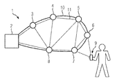
- Fig 1 shows a plurality of units 2 - 8 that make up a danger management system 1.
- the units 2 - 8 are connected through a field bus 10 (solid line).
- An additional broadband bus 11 (dashed line) links the units 2 - 9.
- Unit 2 is a central unit.
- the safety and security units 3 - 8 can be configured and/or monitored through the central unit 2. Also, the central unit typically receives a signal whenever an alarm is generated by one of the safety and security units 3 - 8. The alarm signal is transmitted through the field bus 10.
- the field bus 10 of the detection unit 1 shown on FIG 1 is arranged as a loop.
- the loop connects all the safety and security units 3 - 8 to the central unit 2.
- the field bus is star-shaped with the safety and security units 3 - 8 surrounding the main unit 2. There will then be separate field bus connections starting from the main unit 2 and connecting to the safety and security units 3 - 8.
- the field bus is a combination of a star-shaped and a loop-shaped bus.
- field buses are RS-232, RS485, FireWire, USB, BACnet. Also, proprietary systems known as P2 or Swing would typically be considered as field buses.
- Unit 9 is a handheld device or a laptop computer or a computer in a control room that communicates with the danger management system 1. An operator may obtain status information about the danger management system 1 and its configuration through unit 9. Unit 9 may also be used to receive a video or audio stream from a safety and security units 3 - 8 in case of a fire or in case of a break-in. Further, unit 9 may be used to deploy a firmware update amongst the units 2 - 8 of the danger management system 1.
- the Unit 9 communicates with the danger management system 1 through a broadband bus 11.
- the broadband bus provides the bandwidth required for video streaming and/or firmware updates.
- Typical examples of broadband buses would be WIFI, WLAN, Ethernet, and/or Bluetooth.
- the broadband bus 11 may be switched on and off.
- a signal is sent to a unit 2- 8 through the field bus. Based on that signal, the unit then activates the broadband bus 11.
- a unit 2 - 8 would activate its WIFI bus as soon as it receives an activation signal from another unit 2 - 8.
- the broadband bus 11 is activated periodically and for a limited time span only. This mode is particularly useful for danger management systems 1 where firmware and/or software updates are periodically deployed.
- the broadband bus 11 of a unit 2 - 8 is activated by the unit itself. Activation happens whenever and alarm is generated. This mode offers advantages for an operator who may connect his unit 9 to the unit 2 - 8 that has generated an alarm. The operator may then use a video camera of a unit 2- 8 to check for burglars or for fire in the vicinity of the unit.
- a unit 2 - 8 after generating an alarm sends an activation signal to adjacent units 2 - 8. Those adjacent units then also activate their broadband buses while the broadband buses of the remaining units remain deactivated or idle.
- one of the units 2 - 8 may act as a router, for instance for WIFI signals.
- This particular embodiment allows for an extension of the broadband network within the danger management system 1. That is, even when one or several units are spaced apart, they may communicate directly with one another. A remote unit that would normally be out of the WIFI range of most other units then receives firmware updates by having its data traffic forwarded through a router unit.
- Both the field bus and the broadband bus require the units 2 - 9 to provide one or several communications modules.
- the field bus 10 may be too weak to supply all the units 3 - 8 with sufficient (electrical) power to continuously run their communications modules for the broadband bus 11. Consequently, at least one unit (2 - 9) may provide an energy buffer.
- the energy buffer is configured to supply energy to at least one communications module of said unit (2 - 9) for a limited time span.
- the energy buffer can be implemented as any device configured to store electric energy such as a capacitor, a super-capacitor or a rechargeable battery.
- a danger management system 1 made up of the aforementioned units 2 - 8 may also comprise visible indicators. These visible indicators are mounted directly to the unit and provide information about the status of each of the buses. In a typical embodiment, green, and red LEDS indicate whether each of the field or broadband buses is up or down.
- a dedicated-purpose field bus is designed for maximum reliability and may not be suited for video streaming or software updates.
- WIFI connectors that may be procured off-the-shelf provide fast and broadband connections but lack the reliability of special purpose field buses. Because of the conflicting technical requirements of reliability and broadband capability, a modification of a field bus to provide broadband capabilities is not cost-effective. Instead, the combination of special-purpose field buses and of a broadband bus is the most advantageous solution in terms of cost and reliability.
Priority Applications (4)
| Application Number | Priority Date | Filing Date | Title |
|---|---|---|---|
| EP14152796.0A EP2899708B1 (de) | 2014-01-28 | 2014-01-28 | Kombination von Bussen für Gefahrenverwaltungssystem |
| RU2015101987A RU2611025C2 (ru) | 2014-01-28 | 2015-01-22 | Комбинация шин для системы управления опасностью |
| CN201510042649.4A CN104809852B (zh) | 2014-01-28 | 2015-01-28 | 用于危险管理系统的总线的组合 |
| US14/607,268 US10282336B2 (en) | 2014-01-28 | 2015-01-28 | Combination of buses for a hazard management system, hazard management system, and method of operating the hazard management system |
Applications Claiming Priority (1)
| Application Number | Priority Date | Filing Date | Title |
|---|---|---|---|
| EP14152796.0A EP2899708B1 (de) | 2014-01-28 | 2014-01-28 | Kombination von Bussen für Gefahrenverwaltungssystem |
Publications (2)
| Publication Number | Publication Date |
|---|---|
| EP2899708A1 true EP2899708A1 (de) | 2015-07-29 |
| EP2899708B1 EP2899708B1 (de) | 2017-05-17 |
Family
ID=49999832
Family Applications (1)
| Application Number | Title | Priority Date | Filing Date |
|---|---|---|---|
| EP14152796.0A Active EP2899708B1 (de) | 2014-01-28 | 2014-01-28 | Kombination von Bussen für Gefahrenverwaltungssystem |
Country Status (4)
| Country | Link |
|---|---|
| US (1) | US10282336B2 (de) |
| EP (1) | EP2899708B1 (de) |
| CN (1) | CN104809852B (de) |
| RU (1) | RU2611025C2 (de) |
Families Citing this family (5)
| Publication number | Priority date | Publication date | Assignee | Title |
|---|---|---|---|---|
| EP2983145A1 (de) * | 2014-08-05 | 2016-02-10 | Siemens Schweiz AG | Meldersockel und Anschlussbasis zur lösbaren Anbringung eines Gefahrenmelders mit jeweils einer Funkeinrichtung zum Aussenden von Positionsdaten des Montageorts des Meldersockels bzw. der Anschlussbasis und/oder eines Verweises auf diese Positionsdaten |
| US9861151B2 (en) * | 2014-12-05 | 2018-01-09 | SaPHIBeat Technologies, Inc. | Activity monitoring systems and methods for accident detection and response |
| CN105825152A (zh) * | 2016-04-04 | 2016-08-03 | 合肥博雷电子信息技术有限公司 | 一种计算机网络自动控制装置 |
| EP3839911A1 (de) * | 2019-12-17 | 2021-06-23 | Carrier Corporation | Brandschutzsystem |
| EP3839912A1 (de) * | 2019-12-20 | 2021-06-23 | Carrier Corporation | Feuermeldersystem mit redundanten kommunikationsverbindungen |
Citations (6)
| Publication number | Priority date | Publication date | Assignee | Title |
|---|---|---|---|---|
| EP1398746A1 (de) | 2002-09-07 | 2004-03-17 | Siemens Building Technologies AG | Gefahrenmelder mit Kommunikationsschnittstelle, und Bedienungsmodul |
| EP1510988A2 (de) * | 2003-08-18 | 2005-03-02 | Siemens Schweiz AG | Übertragungsnetzwerk für die Übertragung mehrerer Informationsströme sowie Gefahrenmeldeanlage |
| WO2005055522A2 (en) * | 2003-12-03 | 2005-06-16 | Atop Innovation S.P.A. | System of monitoring and remote intervention |
| US7099755B2 (en) * | 2003-05-30 | 2006-08-29 | Siemens Aktiengesellschaft | Automation and platform management system for naval vessels |
| EP2568475A1 (de) | 2011-09-10 | 2013-03-13 | Université Catholique De Louvain | Magnet und Verfahren zum Entwerfen eines Magnets |
| EP2568457A1 (de) | 2011-09-06 | 2013-03-13 | Siemens Aktiengesellschaft | Verfahren zum Betrieb eines zentralenlosen Gefahrenmeldesystems und zentralenloses Gefahrenmeldesystem |
Family Cites Families (10)
| Publication number | Priority date | Publication date | Assignee | Title |
|---|---|---|---|---|
| US6385772B1 (en) * | 1998-04-30 | 2002-05-07 | Texas Instruments Incorporated | Monitoring system having wireless remote viewing and control |
| DE19908230A1 (de) * | 1999-02-25 | 2000-08-31 | Heidelberger Druckmasch Ag | Vorrichtung zur Überwachung von sicherheitsrelevanten Vorgängen an Maschinen |
| US20040255193A1 (en) * | 2003-06-12 | 2004-12-16 | Larson Thane M. | Inter integrated circuit router error management system and method |
| RU2250504C1 (ru) * | 2003-07-18 | 2005-04-20 | Мироничев Сергей Юрьевич | Способ многоканального видеоаудионаблюдения и реализующая его интегрированная высокочастотная система |
| JP3968525B2 (ja) | 2004-03-04 | 2007-08-29 | ソニー株式会社 | 位相同期回路および情報再生装置 |
| RU2286604C2 (ru) * | 2004-07-08 | 2006-10-27 | ООО НПК "Элекнет" | Приемо-передающий модуль управления, обработки информационных данных и сигнализации для локальных компьютерных сетей |
| CN101247515A (zh) | 2008-03-17 | 2008-08-20 | 清华大学 | 一种用于家庭安防的无线低功耗远程监控摄像装置 |
| GB0903836D0 (en) * | 2009-03-05 | 2009-04-22 | Oxford Instr Plasma Technology | Interface module and controller network |
| JP6043348B2 (ja) * | 2011-07-11 | 2016-12-14 | バルメット オートメーション オイ | 産業プロセスを監視する方法 |
| US9564727B2 (en) * | 2012-07-11 | 2017-02-07 | Weidmueller Interface Gmbh & Co. Kg | Crimping apparatus for turned contacts |
-
2014
- 2014-01-28 EP EP14152796.0A patent/EP2899708B1/de active Active
-
2015
- 2015-01-22 RU RU2015101987A patent/RU2611025C2/ru active
- 2015-01-28 CN CN201510042649.4A patent/CN104809852B/zh active Active
- 2015-01-28 US US14/607,268 patent/US10282336B2/en active Active
Patent Citations (6)
| Publication number | Priority date | Publication date | Assignee | Title |
|---|---|---|---|---|
| EP1398746A1 (de) | 2002-09-07 | 2004-03-17 | Siemens Building Technologies AG | Gefahrenmelder mit Kommunikationsschnittstelle, und Bedienungsmodul |
| US7099755B2 (en) * | 2003-05-30 | 2006-08-29 | Siemens Aktiengesellschaft | Automation and platform management system for naval vessels |
| EP1510988A2 (de) * | 2003-08-18 | 2005-03-02 | Siemens Schweiz AG | Übertragungsnetzwerk für die Übertragung mehrerer Informationsströme sowie Gefahrenmeldeanlage |
| WO2005055522A2 (en) * | 2003-12-03 | 2005-06-16 | Atop Innovation S.P.A. | System of monitoring and remote intervention |
| EP2568457A1 (de) | 2011-09-06 | 2013-03-13 | Siemens Aktiengesellschaft | Verfahren zum Betrieb eines zentralenlosen Gefahrenmeldesystems und zentralenloses Gefahrenmeldesystem |
| EP2568475A1 (de) | 2011-09-10 | 2013-03-13 | Université Catholique De Louvain | Magnet und Verfahren zum Entwerfen eines Magnets |
Also Published As
| Publication number | Publication date |
|---|---|
| RU2015101987A (ru) | 2016-08-10 |
| CN104809852A (zh) | 2015-07-29 |
| US10282336B2 (en) | 2019-05-07 |
| RU2611025C2 (ru) | 2017-02-17 |
| CN104809852B (zh) | 2018-07-10 |
| EP2899708B1 (de) | 2017-05-17 |
| US20150212965A1 (en) | 2015-07-30 |
Similar Documents
| Publication | Publication Date | Title |
|---|---|---|
| US10282336B2 (en) | Combination of buses for a hazard management system, hazard management system, and method of operating the hazard management system | |
| EP2817890B1 (de) | System und verfahren zur überwachung und verwaltung einer anlage mit doppelter kommunikationsschnittstelle | |
| US20150326314A1 (en) | Tandem, Visible Light and RF Communication System | |
| KR20180010500A (ko) | 화재 수신기와 연계가 가능한 방재 시스템 | |
| US9368009B2 (en) | Home automation system monitored by security system | |
| US10375802B2 (en) | Building equipment-based communication system | |
| JP2009002611A (ja) | 空気調和システム | |
| US20170196069A1 (en) | Combination of Led Lamp and Wireless mesh Environmental Sensors Network | |
| DE102009046096A1 (de) | Alarmeinrichtung zur Erkennung und Mitteilung von umgebungs- und anlagenspezifischen Zuständen | |
| JP2015087883A (ja) | 警報器 | |
| AU2018100130A4 (en) | Video monitoring device | |
| US7456728B2 (en) | Fire-alarm control panel having power frequency carrier | |
| CN108922109A (zh) | 一种基于nb-iot技术的消防报警系统 | |
| KR101693215B1 (ko) | 자가 설치 및 운용 가능한 무인경비시스템을 위한 통합센서관제장치 및 방법 | |
| KR20110108038A (ko) | 현장 설정 관리가 가능한 p형 수신기를 이용한 화재 모니터링 시스템 | |
| KR101546731B1 (ko) | 무선중계기가 구성된 화재감지시스템 | |
| EP4231266A1 (de) | Peripheriegerät für gebäudesicherheitsüberwachungssysteme | |
| JP2015014986A (ja) | 警報器及び警報システム | |
| JP2023061682A (ja) | 警報システム | |
| KR100959948B1 (ko) | 비상상황 무선통보 시스템 | |
| KR101159524B1 (ko) | 무선통신을 이용한 보안 시스템 | |
| JP2022030963A (ja) | 無線監視システム | |
| JP2010003302A (ja) | 無線機システム | |
| KR20200077294A (ko) | 비상연동제어를 수행하는 공기조화기 시스템 | |
| JP2006338087A (ja) | セキュリティ装置 |
Legal Events
| Date | Code | Title | Description |
|---|---|---|---|
| PUAI | Public reference made under article 153(3) epc to a published international application that has entered the european phase |
Free format text: ORIGINAL CODE: 0009012 |
|
| 17P | Request for examination filed |
Effective date: 20140128 |
|
| AK | Designated contracting states |
Kind code of ref document: A1 Designated state(s): AL AT BE BG CH CY CZ DE DK EE ES FI FR GB GR HR HU IE IS IT LI LT LU LV MC MK MT NL NO PL PT RO RS SE SI SK SM TR |
|
| AX | Request for extension of the european patent |
Extension state: BA ME |
|
| 17P | Request for examination filed |
Effective date: 20160107 |
|
| RBV | Designated contracting states (corrected) |
Designated state(s): AL AT BE BG CH CY CZ DE DK EE ES FI FR GB GR HR HU IE IS IT LI LT LU LV MC MK MT NL NO PL PT RO RS SE SI SK SM TR |
|
| GRAP | Despatch of communication of intention to grant a patent |
Free format text: ORIGINAL CODE: EPIDOSNIGR1 |
|
| STAA | Information on the status of an ep patent application or granted ep patent |
Free format text: STATUS: GRANT OF PATENT IS INTENDED |
|
| INTG | Intention to grant announced |
Effective date: 20161216 |
|
| GRAS | Grant fee paid |
Free format text: ORIGINAL CODE: EPIDOSNIGR3 |
|
| GRAA | (expected) grant |
Free format text: ORIGINAL CODE: 0009210 |
|
| STAA | Information on the status of an ep patent application or granted ep patent |
Free format text: STATUS: THE PATENT HAS BEEN GRANTED |
|
| AK | Designated contracting states |
Kind code of ref document: B1 Designated state(s): AL AT BE BG CH CY CZ DE DK EE ES FI FR GB GR HR HU IE IS IT LI LT LU LV MC MK MT NL NO PL PT RO RS SE SI SK SM TR |
|
| REG | Reference to a national code |
Ref country code: GB Ref legal event code: FG4D |
|
| REG | Reference to a national code |
Ref country code: CH Ref legal event code: EP |
|
| REG | Reference to a national code |
Ref country code: IE Ref legal event code: FG4D |
|
| REG | Reference to a national code |
Ref country code: AT Ref legal event code: REF Ref document number: 895102 Country of ref document: AT Kind code of ref document: T Effective date: 20170615 |
|
| REG | Reference to a national code |
Ref country code: DE Ref legal event code: R096 Ref document number: 602014009813 Country of ref document: DE |
|
| REG | Reference to a national code |
Ref country code: NL Ref legal event code: MP Effective date: 20170517 |
|
| REG | Reference to a national code |
Ref country code: LT Ref legal event code: MG4D |
|
| PG25 | Lapsed in a contracting state [announced via postgrant information from national office to epo] |
Ref country code: NO Free format text: LAPSE BECAUSE OF FAILURE TO SUBMIT A TRANSLATION OF THE DESCRIPTION OR TO PAY THE FEE WITHIN THE PRESCRIBED TIME-LIMIT Effective date: 20170817 Ref country code: GR Free format text: LAPSE BECAUSE OF FAILURE TO SUBMIT A TRANSLATION OF THE DESCRIPTION OR TO PAY THE FEE WITHIN THE PRESCRIBED TIME-LIMIT Effective date: 20170818 Ref country code: LT Free format text: LAPSE BECAUSE OF FAILURE TO SUBMIT A TRANSLATION OF THE DESCRIPTION OR TO PAY THE FEE WITHIN THE PRESCRIBED TIME-LIMIT Effective date: 20170517 Ref country code: FI Free format text: LAPSE BECAUSE OF FAILURE TO SUBMIT A TRANSLATION OF THE DESCRIPTION OR TO PAY THE FEE WITHIN THE PRESCRIBED TIME-LIMIT Effective date: 20170517 Ref country code: HR Free format text: LAPSE BECAUSE OF FAILURE TO SUBMIT A TRANSLATION OF THE DESCRIPTION OR TO PAY THE FEE WITHIN THE PRESCRIBED TIME-LIMIT Effective date: 20170517 Ref country code: ES Free format text: LAPSE BECAUSE OF FAILURE TO SUBMIT A TRANSLATION OF THE DESCRIPTION OR TO PAY THE FEE WITHIN THE PRESCRIBED TIME-LIMIT Effective date: 20170517 |
|
| PG25 | Lapsed in a contracting state [announced via postgrant information from national office to epo] |
Ref country code: NL Free format text: LAPSE BECAUSE OF FAILURE TO SUBMIT A TRANSLATION OF THE DESCRIPTION OR TO PAY THE FEE WITHIN THE PRESCRIBED TIME-LIMIT Effective date: 20170517 Ref country code: BG Free format text: LAPSE BECAUSE OF FAILURE TO SUBMIT A TRANSLATION OF THE DESCRIPTION OR TO PAY THE FEE WITHIN THE PRESCRIBED TIME-LIMIT Effective date: 20170817 Ref country code: RS Free format text: LAPSE BECAUSE OF FAILURE TO SUBMIT A TRANSLATION OF THE DESCRIPTION OR TO PAY THE FEE WITHIN THE PRESCRIBED TIME-LIMIT Effective date: 20170517 Ref country code: IS Free format text: LAPSE BECAUSE OF FAILURE TO SUBMIT A TRANSLATION OF THE DESCRIPTION OR TO PAY THE FEE WITHIN THE PRESCRIBED TIME-LIMIT Effective date: 20170917 Ref country code: SE Free format text: LAPSE BECAUSE OF FAILURE TO SUBMIT A TRANSLATION OF THE DESCRIPTION OR TO PAY THE FEE WITHIN THE PRESCRIBED TIME-LIMIT Effective date: 20170517 Ref country code: LV Free format text: LAPSE BECAUSE OF FAILURE TO SUBMIT A TRANSLATION OF THE DESCRIPTION OR TO PAY THE FEE WITHIN THE PRESCRIBED TIME-LIMIT Effective date: 20170517 Ref country code: PL Free format text: LAPSE BECAUSE OF FAILURE TO SUBMIT A TRANSLATION OF THE DESCRIPTION OR TO PAY THE FEE WITHIN THE PRESCRIBED TIME-LIMIT Effective date: 20170517 |
|
| REG | Reference to a national code |
Ref country code: FR Ref legal event code: PLFP Year of fee payment: 5 |
|
| PG25 | Lapsed in a contracting state [announced via postgrant information from national office to epo] |
Ref country code: SK Free format text: LAPSE BECAUSE OF FAILURE TO SUBMIT A TRANSLATION OF THE DESCRIPTION OR TO PAY THE FEE WITHIN THE PRESCRIBED TIME-LIMIT Effective date: 20170517 Ref country code: RO Free format text: LAPSE BECAUSE OF FAILURE TO SUBMIT A TRANSLATION OF THE DESCRIPTION OR TO PAY THE FEE WITHIN THE PRESCRIBED TIME-LIMIT Effective date: 20170517 Ref country code: CZ Free format text: LAPSE BECAUSE OF FAILURE TO SUBMIT A TRANSLATION OF THE DESCRIPTION OR TO PAY THE FEE WITHIN THE PRESCRIBED TIME-LIMIT Effective date: 20170517 Ref country code: EE Free format text: LAPSE BECAUSE OF FAILURE TO SUBMIT A TRANSLATION OF THE DESCRIPTION OR TO PAY THE FEE WITHIN THE PRESCRIBED TIME-LIMIT Effective date: 20170517 Ref country code: DK Free format text: LAPSE BECAUSE OF FAILURE TO SUBMIT A TRANSLATION OF THE DESCRIPTION OR TO PAY THE FEE WITHIN THE PRESCRIBED TIME-LIMIT Effective date: 20170517 |
|
| REG | Reference to a national code |
Ref country code: DE Ref legal event code: R097 Ref document number: 602014009813 Country of ref document: DE |
|
| PG25 | Lapsed in a contracting state [announced via postgrant information from national office to epo] |
Ref country code: SM Free format text: LAPSE BECAUSE OF FAILURE TO SUBMIT A TRANSLATION OF THE DESCRIPTION OR TO PAY THE FEE WITHIN THE PRESCRIBED TIME-LIMIT Effective date: 20170517 Ref country code: IT Free format text: LAPSE BECAUSE OF FAILURE TO SUBMIT A TRANSLATION OF THE DESCRIPTION OR TO PAY THE FEE WITHIN THE PRESCRIBED TIME-LIMIT Effective date: 20170517 |
|
| PLBE | No opposition filed within time limit |
Free format text: ORIGINAL CODE: 0009261 |
|
| STAA | Information on the status of an ep patent application or granted ep patent |
Free format text: STATUS: NO OPPOSITION FILED WITHIN TIME LIMIT |
|
| 26N | No opposition filed |
Effective date: 20180220 |
|
| PG25 | Lapsed in a contracting state [announced via postgrant information from national office to epo] |
Ref country code: SI Free format text: LAPSE BECAUSE OF FAILURE TO SUBMIT A TRANSLATION OF THE DESCRIPTION OR TO PAY THE FEE WITHIN THE PRESCRIBED TIME-LIMIT Effective date: 20170517 |
|
| PG25 | Lapsed in a contracting state [announced via postgrant information from national office to epo] |
Ref country code: LU Free format text: LAPSE BECAUSE OF NON-PAYMENT OF DUE FEES Effective date: 20180128 |
|
| REG | Reference to a national code |
Ref country code: IE Ref legal event code: MM4A |
|
| REG | Reference to a national code |
Ref country code: BE Ref legal event code: MM Effective date: 20180131 |
|
| PG25 | Lapsed in a contracting state [announced via postgrant information from national office to epo] |
Ref country code: BE Free format text: LAPSE BECAUSE OF NON-PAYMENT OF DUE FEES Effective date: 20180131 |
|
| PG25 | Lapsed in a contracting state [announced via postgrant information from national office to epo] |
Ref country code: IE Free format text: LAPSE BECAUSE OF NON-PAYMENT OF DUE FEES Effective date: 20180128 |
|
| PG25 | Lapsed in a contracting state [announced via postgrant information from national office to epo] |
Ref country code: MC Free format text: LAPSE BECAUSE OF FAILURE TO SUBMIT A TRANSLATION OF THE DESCRIPTION OR TO PAY THE FEE WITHIN THE PRESCRIBED TIME-LIMIT Effective date: 20170517 |
|
| PG25 | Lapsed in a contracting state [announced via postgrant information from national office to epo] |
Ref country code: MT Free format text: LAPSE BECAUSE OF NON-PAYMENT OF DUE FEES Effective date: 20180128 |
|
| PG25 | Lapsed in a contracting state [announced via postgrant information from national office to epo] |
Ref country code: TR Free format text: LAPSE BECAUSE OF FAILURE TO SUBMIT A TRANSLATION OF THE DESCRIPTION OR TO PAY THE FEE WITHIN THE PRESCRIBED TIME-LIMIT Effective date: 20170517 |
|
| PG25 | Lapsed in a contracting state [announced via postgrant information from national office to epo] |
Ref country code: PT Free format text: LAPSE BECAUSE OF FAILURE TO SUBMIT A TRANSLATION OF THE DESCRIPTION OR TO PAY THE FEE WITHIN THE PRESCRIBED TIME-LIMIT Effective date: 20170517 |
|
| PG25 | Lapsed in a contracting state [announced via postgrant information from national office to epo] |
Ref country code: CY Free format text: LAPSE BECAUSE OF FAILURE TO SUBMIT A TRANSLATION OF THE DESCRIPTION OR TO PAY THE FEE WITHIN THE PRESCRIBED TIME-LIMIT Effective date: 20170517 Ref country code: MK Free format text: LAPSE BECAUSE OF NON-PAYMENT OF DUE FEES Effective date: 20170517 Ref country code: HU Free format text: LAPSE BECAUSE OF FAILURE TO SUBMIT A TRANSLATION OF THE DESCRIPTION OR TO PAY THE FEE WITHIN THE PRESCRIBED TIME-LIMIT; INVALID AB INITIO Effective date: 20140128 |
|
| PG25 | Lapsed in a contracting state [announced via postgrant information from national office to epo] |
Ref country code: AL Free format text: LAPSE BECAUSE OF FAILURE TO SUBMIT A TRANSLATION OF THE DESCRIPTION OR TO PAY THE FEE WITHIN THE PRESCRIBED TIME-LIMIT Effective date: 20170517 |
|
| REG | Reference to a national code |
Ref country code: AT Ref legal event code: UEP Ref document number: 895102 Country of ref document: AT Kind code of ref document: T Effective date: 20170517 |
|
| PGFP | Annual fee paid to national office [announced via postgrant information from national office to epo] |
Ref country code: FR Payment date: 20230113 Year of fee payment: 10 Ref country code: AT Payment date: 20221209 Year of fee payment: 10 |
|
| PGFP | Annual fee paid to national office [announced via postgrant information from national office to epo] |
Ref country code: GB Payment date: 20230202 Year of fee payment: 10 Ref country code: DE Payment date: 20220620 Year of fee payment: 10 |
|
| PGFP | Annual fee paid to national office [announced via postgrant information from national office to epo] |
Ref country code: CH Payment date: 20230412 Year of fee payment: 10 |
|
| PGFP | Annual fee paid to national office [announced via postgrant information from national office to epo] |
Ref country code: AT Payment date: 20231211 Year of fee payment: 11 |
|
| PGFP | Annual fee paid to national office [announced via postgrant information from national office to epo] |
Ref country code: DE Payment date: 20240318 Year of fee payment: 11 Ref country code: GB Payment date: 20240212 Year of fee payment: 11 |