EP2899406B1 - Kühlmodul mit schallgedämmtem gebläse - Google Patents
Kühlmodul mit schallgedämmtem gebläse Download PDFInfo
- Publication number
- EP2899406B1 EP2899406B1 EP15150394.3A EP15150394A EP2899406B1 EP 2899406 B1 EP2899406 B1 EP 2899406B1 EP 15150394 A EP15150394 A EP 15150394A EP 2899406 B1 EP2899406 B1 EP 2899406B1
- Authority
- EP
- European Patent Office
- Prior art keywords
- cooling module
- module according
- fan wheel
- absorber
- wall
- Prior art date
- Legal status (The legal status is an assumption and is not a legal conclusion. Google has not performed a legal analysis and makes no representation as to the accuracy of the status listed.)
- Not-in-force
Links
- 238000001816 cooling Methods 0.000 title claims description 46
- 239000006096 absorbing agent Substances 0.000 claims description 46
- 238000005192 partition Methods 0.000 claims description 25
- 238000005452 bending Methods 0.000 claims description 3
- 229910052751 metal Inorganic materials 0.000 claims description 2
- 239000002184 metal Substances 0.000 claims description 2
- 238000009413 insulation Methods 0.000 description 15
- 239000002826 coolant Substances 0.000 description 10
- 239000012080 ambient air Substances 0.000 description 9
- 239000003570 air Substances 0.000 description 3
- 238000004519 manufacturing process Methods 0.000 description 3
- 229910052782 aluminium Inorganic materials 0.000 description 2
- XAGFODPZIPBFFR-UHFFFAOYSA-N aluminium Chemical compound [Al] XAGFODPZIPBFFR-UHFFFAOYSA-N 0.000 description 2
- 239000000110 cooling liquid Substances 0.000 description 2
- 239000000428 dust Substances 0.000 description 2
- 238000007710 freezing Methods 0.000 description 2
- 230000008014 freezing Effects 0.000 description 2
- 239000007788 liquid Substances 0.000 description 2
- XLYOFNOQVPJJNP-UHFFFAOYSA-N water Substances O XLYOFNOQVPJJNP-UHFFFAOYSA-N 0.000 description 2
- 101100498160 Mus musculus Dach1 gene Proteins 0.000 description 1
- 238000004378 air conditioning Methods 0.000 description 1
- 230000002238 attenuated effect Effects 0.000 description 1
- 230000005494 condensation Effects 0.000 description 1
- 238000009833 condensation Methods 0.000 description 1
- 238000010276 construction Methods 0.000 description 1
- 238000011982 device technology Methods 0.000 description 1
- 238000005516 engineering process Methods 0.000 description 1
- 239000002657 fibrous material Substances 0.000 description 1
- 239000006260 foam Substances 0.000 description 1
- 239000011888 foil Substances 0.000 description 1
- 239000012774 insulation material Substances 0.000 description 1
- 238000005457 optimization Methods 0.000 description 1
- 230000003584 silencer Effects 0.000 description 1
Images

Classifications
-
- F—MECHANICAL ENGINEERING; LIGHTING; HEATING; WEAPONS; BLASTING
- F04—POSITIVE - DISPLACEMENT MACHINES FOR LIQUIDS; PUMPS FOR LIQUIDS OR ELASTIC FLUIDS
- F04D—NON-POSITIVE-DISPLACEMENT PUMPS
- F04D29/00—Details, component parts, or accessories
- F04D29/40—Casings; Connections of working fluid
- F04D29/42—Casings; Connections of working fluid for radial or helico-centrifugal pumps
- F04D29/4206—Casings; Connections of working fluid for radial or helico-centrifugal pumps especially adapted for elastic fluid pumps
- F04D29/4226—Fan casings
-
- F—MECHANICAL ENGINEERING; LIGHTING; HEATING; WEAPONS; BLASTING
- F04—POSITIVE - DISPLACEMENT MACHINES FOR LIQUIDS; PUMPS FOR LIQUIDS OR ELASTIC FLUIDS
- F04D—NON-POSITIVE-DISPLACEMENT PUMPS
- F04D29/00—Details, component parts, or accessories
- F04D29/66—Combating cavitation, whirls, noise, vibration or the like; Balancing
- F04D29/661—Combating cavitation, whirls, noise, vibration or the like; Balancing especially adapted for elastic fluid pumps
- F04D29/663—Sound attenuation
- F04D29/665—Sound attenuation by means of resonance chambers or interference
-
- F—MECHANICAL ENGINEERING; LIGHTING; HEATING; WEAPONS; BLASTING
- F04—POSITIVE - DISPLACEMENT MACHINES FOR LIQUIDS; PUMPS FOR LIQUIDS OR ELASTIC FLUIDS
- F04D—NON-POSITIVE-DISPLACEMENT PUMPS
- F04D25/00—Pumping installations or systems
- F04D25/16—Combinations of two or more pumps ; Producing two or more separate gas flows
- F04D25/166—Combinations of two or more pumps ; Producing two or more separate gas flows using fans
-
- F—MECHANICAL ENGINEERING; LIGHTING; HEATING; WEAPONS; BLASTING
- F05—INDEXING SCHEMES RELATING TO ENGINES OR PUMPS IN VARIOUS SUBCLASSES OF CLASSES F01-F04
- F05D—INDEXING SCHEME FOR ASPECTS RELATING TO NON-POSITIVE-DISPLACEMENT MACHINES OR ENGINES, GAS-TURBINES OR JET-PROPULSION PLANTS
- F05D2250/00—Geometry
- F05D2250/10—Two-dimensional
- F05D2250/19—Two-dimensional machined; miscellaneous
- F05D2250/191—Two-dimensional machined; miscellaneous perforated
-
- F—MECHANICAL ENGINEERING; LIGHTING; HEATING; WEAPONS; BLASTING
- F05—INDEXING SCHEMES RELATING TO ENGINES OR PUMPS IN VARIOUS SUBCLASSES OF CLASSES F01-F04
- F05D—INDEXING SCHEME FOR ASPECTS RELATING TO NON-POSITIVE-DISPLACEMENT MACHINES OR ENGINES, GAS-TURBINES OR JET-PROPULSION PLANTS
- F05D2260/00—Function
- F05D2260/96—Preventing, counteracting or reducing vibration or noise
- F05D2260/963—Preventing, counteracting or reducing vibration or noise by Helmholtz resonators
Definitions
- the invention relates to a cooling module according to the preamble of claim 1.
- Such cooling modules have a fan wheel, via which ambient air is conveyed through a cooler of the cooling module.
- a coolant that was previously used for cooling at a distance from the cooling module is returned to the cooler in a circuit and is then cooled again. The coolant can then be used again for cooling.
- Such cooling modules are mounted, for example, on the roofs of rail vehicles in which there are people. The coolant is then pumped into the components of the rail vehicle to be cooled.
- a disadvantage of such cooling modules is that disruptive noises from the fan wheel are amplified via the housing of the cooling module and can be transmitted into the interior and the surroundings.
- the DE 26 28 511 shows such a silencer for a fan, the housing of which has a box-shaped outer wall and a curved inner wall called a fan spiral. In between, sound-absorbing cavities are formed via partition walls, into which insulation material is inserted. Perforated areas are provided for each cavity in the curved inner wall.
- a disadvantage of such sound insulation is that, in addition to dust, it also absorbs rain or condensation water or even leaked cooling liquid, which reduces its durability. In particular, such sound insulation can be damaged after exposure to liquids at temperatures below freezing point.
- the EP 1 980 755 A2 shows part of an air conditioning system that is placed outdoors. It has a fan that is inserted into a front surface of a case. On an inside of the front surface, a plurality of mufflers are provided on the circumference of the fan wheel, which have one or more inner perforated plates and an outer closed plate. Unfilled chambers are formed in between. The mufflers also have side panels that must be attached to the inner perforated panels.
- the invention is based on the object of creating a cooling module in which these disadvantages are avoided.
- the claimed cooling module has a housing and a fan wheel rotating in it (for example a paddle wheel).
- a wall section of the housing according to the invention has several chambers, which are delimited at least on the inside by a micro-perforated absorber extending over several chambers and further by partition walls arranged in the interior of the wall section.
- the micro-perforated absorber has a large number of comparatively small through openings.
- the chambers are separated from one another by the partition walls. This creates a cooling module in which the durability of the sound insulation is improved. In particular, after exposure to dust and liquid (water or cooling liquid), such sound insulation can also withstand temperatures below freezing point and be cleaned.
- a wall section is also to be understood as meaning a base or a cover of the housing.
- the absorber is in one piece over a certain area.
- the absorber forms several inner flat wall elements and has contact sections arranged between them.
- the contact sections of the absorber are in contact with and attached to an outer flat wall element. In this way, the absorber is kept at the selected distance from the outer wall element, which determines the depth of the chambers.
- the absorber is formed from a sheet metal and has several mutually parallel bending points. Then two mutually adjacent bending points can delimit a contact section or an inner wall element in pairs.
- the passage recesses preferably have a proportion of an area of the absorber of a few percent (in particular less than 8 percent).
- the through cutouts are microslots.
- the wall section has an outer flat wall element or an outer wall surface and an inner flat wall element or an inner wall surface.
- the micro-perforated absorber forms at least the inner wall element or the inner wall surface.
- the outer wall element of the wall section is closed.
- the chambers are thus delimited on the inside by the absorber and on the outside by a sound-reflecting wall element.
- individual or all wall sections of the housing can be lined on the inside with the absorber and provided with the chambers for sound insulation.
- the outer wall element of the wall section is also formed by an absorber.
- the chambers are thus delimited on the outside and inside by absorbers and furthermore by the partition walls.
- the outer sound system boundary of the cooling module is thus formed by micro-perforated absorber.
- the wall section has one or more middle flat wall elements or middle wall surfaces. Two or more levels of chambers are thus formed in the wall section.
- the distances between the various wall elements can also be dimensioned differently and thus adapted to the sound frequency to be insulated.
- the planes formed in this way can have different thicknesses and thus chamber depths.
- partition walls are arranged between the wall elements and perpendicular to the wall elements.
- the partition walls can form a polygonal honeycomb structure.
- the partition walls can form a rectangular or square lattice structure.
- the partition walls are preferably firmly connected to the flat wall elements. For this purpose, they can be glued, welded, soldered or clamped between the wall elements with an elastic seal. This prevents an acoustic "short circuit" between the partition walls.
- the housing has a frame structure so that the housing has a box-like structure.
- the at least one wall section provided with chambers according to the invention is then inserted into a frame of this frame structure and / or attached to pins of the frame structure.
- the fan wheel forms a radial fan which sucks in ambient air axially via a cooler and discharges it radially.
- the fan wheel can also form an axial fan.
- micro-perforated absorber elements can be arranged on the circumference of the fan wheel for further sound insulation, which have a specific angle and radial distance to the fan wheel.
- the further absorber elements can be arranged in one or more rows.
- the other absorber elements can have an air-conducting function.
- the wall section formed according to the invention with absorber and chambers or further absorber foils can be arranged parallel or along an air flow.
- the absorber can be made of plastic.
- the cooling module can have a further fan wheel, one or more wall sections according to the invention (also) being arranged between them.
- the housing can have or delimit a blow-out duct which is arranged behind the fan wheel in the direction of flow of the air flow.
- the exhaust duct can (also) have a wall section according to the invention for sound insulation.
- the housing can have or delimit an intake duct which is arranged in front of the fan wheel in the direction of flow of the air flow. Then the intake duct can (also) have a wall section according to the invention for sound insulation.
- the size of the chambers can be designed depending on the blade frequency of the rotating fan wheel to be insulated.
- the blade frequency can be determined from the primary rotational frequency (for example nominal rotational frequency) of the fan wheel and the number of blade blades of the fan wheel.
- the airfoil frequency can be 440 Hz in one application.
- the size of the chambers is defined by the distance between the wall sections and the distance between the partition walls.
- the cooling module according to the invention has supports which are designed to fasten the cooling module to a roof, in particular a rail vehicle.
- coolant is guided through the radiator 2 via a coolant pump 8 and from there into an interior space of the rail vehicle (both not shown).
- a radial fan wheel arranged inside the fan wheel housing 6 (cf. Figure 2 ) Ambient air is sucked through the cooler 2 and through the intermediate housing 4 into the fan wheel housing 6.
- the radial fan wheel is driven by an electric motor 16.
- the ambient air is discharged from the fan wheel housing 6 through the blow-out channel 10 formed thereon to the environment.
- the ambient air after it has absorbed heat from the supplied coolant in the cooler 2, is thus guided through a housing of the cooling module, which essentially consists of the intermediate housing 4, the fan wheel housing 6 and the blow-out duct 10.
- FIG 2 shows the cooling module according to Figure 1 in a partially sectioned side view. Going beyond the coolant pump 8 and the two cross members 1 shown in section, a section through the fan wheel housing 6 is shown in particular.
- the radial fan wheel 12 is arranged adjacent to a wall section 14 of the fan wheel housing 6. The ambient air flows axially through to the radial fan wheel 12 and leaves it radially.
- the wall section 14 is formed in one piece with a wall section of the blow-out duct 10. Furthermore, a cover 20 and a base 22 of the fan wheel housing 6 are shown, the base 22 being formed in one piece with a base 24 of the blow-out duct 10 angled therefrom.
- a micro-perforated absorber 28 is attached to the cover 20 of the fan wheel housing 6 and to the common wall section 14 of the fan wheel housing 6 and the exhaust duct 10 and to the base 24 of the exhaust duct 10, the absorbers 28 of the cover 20 and the base 24 being cut are shown, while the absorber 28 of the wall section 14 is shown in a view.
- the absorbers 28 are made of aluminum sheet and are angled several times according to a regular scheme. As a result of the bends, each absorber 28 has strip-shaped contact sections 30 which are fastened to the fan wheel housing 6 and which lie essentially flat on the wall section 14 or on the base 24 or on the cover 20.
- strip-shaped sections are formed, between each of which a main section 32 of the absorber 28 designed as an inner flat element is arranged.
- the main sections 32 are preferably arranged parallel to the wall section 14 or to the base 24 or to the cover 20. This creates a plurality of flat spaces 34 which are connected to the interior of the housing 6 only via a multiplicity of microslots which penetrate the absorber 28.
- Figures 3a and 3b each show an exemplary embodiment of regular structures made of partition walls 35; 135, which are set up inside the rooms 34 to separate chambers 36; 136 to form. More precisely, the first embodiment has lattice-like partition walls 35, while the partition walls of the second embodiment are arranged in such a way that honeycomb-like chambers 136 result.
- the height of the partition walls corresponds to 35; 135 and thus the chambers 36; 136 is the height of the spaces 34, which is defined by the distance between the main sections 32 of the absorbers 28 and the outer wall section 14 or from the floor 24 or from the cover 20. This creates chambers, the size of which is designed as a function of the sound frequency to be attenuated.
- FIG 4 shows a second embodiment of the cooling module according to the invention in a partially sectioned view.
- the cooling module has a second cooler 102, which is separated from the incoming ambient air (in Figure 4 from left to right) before it flows through the first cooler 2, the intermediate housing 4 and the fan wheel housing 6.
- the second exemplary embodiment also has a coolant filter 144.
- FIG 4 it is shown that the absorbers 28 are fastened to the respective housing 4, 6 via their contact sections 30 and via rivet nuts 146.
- the rivet nuts 146 penetrate the affected walls and floors and ceilings of the housings 4, 6.
- Some wall sections of the housings 4, 6 have absorbers 28 on their inside through which the spaces 34 are formed into which, according to the invention, grid-like or honeycomb-like regular structures of partition walls are fitted to form chambers.
- Figure 5 shows a housing 206 of a third embodiment of the cooling module according to the invention in a schematic perspective view. It is designed as a frame construction and has profiles 248 along its edges. A flat, precisely fitting wall section 214 is inserted into each of the areas between the profiles 248.
- Figures 6a and 6b show a wall section 214 of the third embodiment according to FIG Figure 5 . More precisely shows Figure 6a the wall section in a perspective view, while Figure 6b shows the wall section 214 in a side sectional view.
- the wall sections are formed from three flat wall elements of micro-perforated absorbers 28, that is to say from an inner wall element 250, a middle wall element 252 and an outer wall element 254. In between, two levels or spaces 34 are formed in which partition walls 35; 135 and chambers 36; 136 (for example according to one of the exemplary embodiments according to FIGS Figures 3a or 3b ) are arranged.
- the partition walls 35; 135 are attached to the wall elements 250, 252, 254 so that the chambers 36; 136 - apart from the perforations designed as microslits - are airtight.
- the outer wall element 254 has holes 256 via which it is pushed onto pins 258 of the profiles 248.
- Figure 7 shows the third embodiment of the cooling module according to Figures 5 and 6 in a schematic sectional view. It is shown that the radial fan wheel 12 conveys the ambient air radially outward. According to the arrows, part of the ambient air penetrates through the microslots of three additional absorber elements 218 distributed around the circumference of the radial fan wheel 12 and of three wall elements 250, 252, 254 Figure 1 ) promoted to the outside world.
- a cooling module with a housing and with a radial fan wheel which serves as a fan for a cooler.
- the housing has an absorber formed from an aluminum sheet, which has a large number of microslots.
- Inner walls of the housing are completely or partially lined with the absorber, as a result of which spaces are formed between the inner wall and the absorber, which spaces are divided into chambers by honeycomb-shaped or grid-shaped partition walls.
- the chambers are with it connected to the interior of the housing only through the micro-slots and dampen the sound of the radial fan wheel.
- the outer housing wall can also be formed by an absorber which has a large number of microslots.
Landscapes
- Engineering & Computer Science (AREA)
- Mechanical Engineering (AREA)
- General Engineering & Computer Science (AREA)
- Cooling Or The Like Of Electrical Apparatus (AREA)
- Structures Of Non-Positive Displacement Pumps (AREA)
Description
- Die Erfindung betrifft ein Kühlmodul gemäß dem Oberbegriff des Patentanspruchs 1.
- Derartige Kühlmodule haben ein Lüfterrad, über das Umgebungsluft durch einen Kühler des Kühlmoduls gefördert wird. Dabei wird ein Kühlmittel, das zuvor entfernt von dem Kühlmodul zur Kühlung genutzt wurde, in einem Kreislauf zum Kühler zurückgeführt und darin wieder abgekühlt. Dann kann das Kühlmittel wieder zur Kühlung genutzt werden.
- Derartige Kühlmodule werden zum Beispiel auf Dächern von Schienenfahrzeugen montiert, in denen sich Menschen befinden. Dann wird das Kühlmittel in die zu kühlenden Komponenten des Schienenfahrzeugs gefördert. Nachteilig an derartigen Kühlmodulen ist, dass störende Geräusche des Lüfterrads über das Gehäuse des Kühlmoduls verstärkt und in den Innenraum und die Umgebung übertragen werden können.
- Aus dem Stand der Technik ist es bekannt, das Gehäuse zur Schalldämmung mit Schaumstoffen oder faserigen Materialien auszukleiden. Die
DE 26 28 511 zeigt einen derartigen Schalldämpfer für ein Gebläse, dessen Gehäuse eine kastenförmige Außenwand und eine als Gebläsespirale bezeichnete gekrümmte Innenwand aufweist. Dazwischen sind über Trennwände schallabsorbierende Hohlräume gebildet, in die Dämmmaterial eingesetzt ist. In der gekrümmten Innenwand sind für jeden Hohlraum perforierte Bereiche vorgesehen. Nachteilig an derartigen Schalldämmungen ist, dass diese neben Staub auch Regen- bzw. Kondenswasser oder auch ausgetretene Kühlflüssigkeit aufsaugen, wodurch ihre Haltbarkeit verringert wird. Insbesondere können derartige Schalldämmungen nach der Beaufschlagung durch Flüssigkeiten bei Temperaturen unter dem Gefrierpunkt beschädigt werden. - Die
EP 1 980 755 A2 zeigt einen Teil einer Klimaanlage, der im Außenbereich angeordnet wird. Er hat ein Lüfterrad, das in eine Vorderfläche eines Gehäuses eingesetzt ist. An einer Innenseite der Vorderfläche sind am Umfang des Lüfterrades mehrere Schalldämpfer vorgesehen, die eine oder mehrere innere perforierte Platten und eine äußere geschlossene Platte aufweisen. Dazwischen sind ungefüllte Kammern ausgebildet. Die Schalldämpfer haben weiterhin Seitenplatten, die an den inneren perforierten Platten befestigt werden müssen. - Dem gegenüber liegt der Erfindung die Aufgabe zu Grunde, ein Kühlmodul zu schaffen, bei dem diese Nachteile vermieden sind.
- Diese Aufgabe wird gelöst durch ein Kühlmodul mit den Merkmalen des Patentanspruchs 1.
- Das beanspruchte Kühlmodul hat ein Gehäuse und ein darin rotierendes Lüfterrad (zum Beispiel Schaufelrad). Zur Schalldämmung weist zumindest ein Wandabschnitt des Gehäuses erfindungsgemäß mehrere Kammern auf, die zumindest innenseitig von einem sich über mehrere Kammern erstreckenden mikro-perforierten Absorber und weiterhin von im Innern des Wandabschnitts angeordneten Trennwänden begrenzt sind. Der mikro-perforierte Absorber hat eine Vielzahl von vergleichsweise kleinen Durchgangsausnehmungen. Die Kammern sind durch die Trennwände voneinander getrennt. Damit ist ein Kühlmodul geschaffen bei dem die Haltbarkeit der Schalldämmung verbessert ist. Insbesondere können derartige Schalldämmungen nach einer Beaufschlagung mit Staub und Flüssigkeit (Wasser oder Kühlflüssigkeit) auch Temperaturen unter dem Gefrierpunkt widerstehen und gereinigt werden. Unter Wandabschnitt ist auch ein Boden oder ein Deckel des Gehäuses zu verstehen.
- Der Absorber ist erfindungsgemäß über eine bestimmte Flächenausdehnung einstückig. Dabei bildet der Absorber mehrere innere flächige Wandelemente und weist dazwischen angeordnete Anlageabschnitte auf. Die Anlageabschnitte des Absorbers sind in Anlage mit und befestigt an einem äußeren flächigen Wandelement. So wird der Absorber im gewählten Abstand zum äußeren Wandelement gehalten, wodurch die Tiefe der Kammern bestimmt ist.
- Erfindungsgemäß ist der Absorber aus einem Blech umgeformt und hat mehrere zueinander parallele Biegestellen. Dann können zwei zueinander benachbarte Biegestellen paarweise einen Anlageabschnitt oder ein inneres Wandelement begrenzen.
- Vorzugsweise haben die Durchgangsausnehmungen einen Anteil an einer Fläche des Absorbers von wenigen Prozent (insbesondere unter 8 Prozent).
- Aus fertigungstechnischen Gründen wird es bevorzugt, wenn die Durchgangsausnehmungen Mikroschlitze sind.
- Bei einem nicht zur Erfindung gehörenden Kühlmodul weist der Wandabschnitt ein äußeres flächiges Wandelement oder eine äußere Wandfläche und ein inneres flächiges Wandelement oder eine innere Wandfläche auf. Der mikro-perforierte Absorber bildet zumindest das innere Wandelement bzw. die innere Wandfläche.
- Bei einer ersten Weiterbildung der Erfindung ist das äußere Wandelement des Wandabschnitts geschlossen. Damit sind die Kammern innenseitig vom Absorber und außenseitig von einem Schall reflektierenden Wandelement begrenzt. Durch die Wahl des Abstands zwischen dem äußeren geschlossenen Wandelement und dem inneren mikro-perforierten Wandelement kann die Schalldämmung an die zu dämmende Schallfrequenz angepasst werden.
- In Abhängigkeit des möglichen Aufwandes und angestrebter Schalldämmung können einzelne oder alle Wandabschnitte des Gehäuses innen mit dem Absorber ausgekleidet und mit den Kammern zur Schalldämmung versehen sein.
- Bei einer zweiten Weiterbildung der Erfindung ist auch das äußere Wandelement des Wandabschnitts von einem Absorber gebildet. Damit sind die Kammern außenseitig und innenseitig von Absorbern und weiterhin von den Trennwänden begrenzt. Damit ist die äußere Schallsystemgrenze des Kühlmoduls von mikro-perforiertem Absorber gebildet. Durch die Wahl des Abstands zwischen dem äußeren mikro-perforierten Wandelement und dem inneren mikro-perforierten Wandelement kann die Schalldämmung an die zu dämmende Schallfrequenz des Kühlmoduls angepasst werden.
- Die Schalldämmung ist weiter verbessert, wenn der Wandabschnitt ein oder mehrere mittlere flächige Wandelemente oder mittlere Wandflächen aufweist. Damit sind zwei oder mehr Ebenen von Kammern in dem Wandabschnitt gebildet. Auch dabei lassen sich die Abstände der verschiedenen Wandelemente (inneres, mittleres und äußeres Wandelement) auch unterschiedlich bemessen und so an die zu dämmende Schallfrequenz anpassen.
- Die so gebildeten Ebenen können unterschiedliche Dicke und damit Kammertiefe aufweisen.
- Vorrichtungstechnisch und fertigungstechnisch einfach ist es, wenn die Trennwände zwischen den Wandelementen und senkrecht zu den Wandelementen angeordnet sind.
- Die Trennwände können gemäß einer ersten Ausgestaltung eine mehreckige Wabenstruktur bilden.
- Die Trennwände können gemäß einer zweiten Ausgestaltung eine rechteckige oder quadratische Gitterstruktur bilden.
- Vorzugsweise sind die Trennwände fest mit den flächigen Wandelementen verbunden. Dazu können sie verklebt, verschweißt, verlötet oder elastisch dichtend zwischen den Wandelementen eingespannt sein. Damit wird ein akustischer "Kurzschluss" zwischen den Trennwänden verhindert.
- Bei einer besonders bevorzugten Weiterbildung hat das Gehäuse eine Rahmenstruktur, so dass sich ein kastenartiger Aufbau des Gehäuses ergibt. Dann wird der zumindest eine erfindungsgemäß mit Kammern versehene Wandabschnitt in einen Rahmen dieser Rahmenstruktur eingesetzt und / oder auf Stifte der Rahmenstruktur aufgesteckt. Damit ergibt sich die Möglichkeit, den Wandabschnitt als ebenes flächiges Teil einfach zu fertigen und an der Rahmenstruktur zu befestigen, zum Beispiel durch Einsetzten zwischen Profile der Rahmenstruktur und / oder durch Aufstecken auf Stifte.
- Insbesondere bei dem kastenartigen Gehäuse wird es im Sinne einer Wirkungsgradoptimierung bevorzugt, wenn das Lüfterrad ein Radialgebläse bildet, das Umgebungsluft axial über einen Kühler ansaugt und radial abführt. Das Lüfterrad kann aber auch ein Axialgebläse bilden.
- Insbesondere im Falle des Radialgebläses können zur weiteren Schalldämmung am Umfang des Lüfterrades weitere mikro-perforierte Absorberelemente angeordnet sein, die einen spezifischen Winkel und Radialabstand zum Lüfterrad haben. Die weiteren Absorberelemente können in einer oder mehreren Reihen angeordnet sein. Die weiteren Absorberelemente können Luft leitende Funktion haben.
- Der erfindungsgemäß mit Absorber und Kammern ausgebildete Wandabschnitt oder weitere Absorberfolien können parallel bzw. entlang einem Luftstrom angeordnet sein.
- Der Absorber kann bei einer nicht zur Erfindung gehörenden Weiterbildung aus Kunststoff gefertigt sein.
- Das Kühlmodul kann ein weiteres Lüfterrad haben, wobei ein oder mehrere erfindungsgemäße Wandabschnitte (auch) zwischen diesen angeordnet sind.
- Das Gehäuse kann einen Ausblaskanal aufweisen oder begrenzen, der in Strömungsrichtung des Luftstroms hinter dem Lüfterrad angeordnet ist. Dann kann (auch) der Ausblaskanal zur Schalldämmung einen erfindungsgemäßen Wandabschnitt aufweisen.
- Das Gehäuse kann einen Ansaugkanal aufweisen oder begrenzen, der in Strömungsrichtung des Luftstroms vor dem Lüfterrad angeordnet ist. Dann kann (auch) der Ansaugkanal zur Schalldämmung einen erfindungsgemäßen Wandabschnitt aufweisen.
- Zur Maximierung der Effektivität des Absorbers kann die Größe der Kammern in Abhängigkeit einer zu dämmenden Schaufelblattfrequenz des rotierenden Lüfterrads ausgelegt werden. Die Schaufelblattfrequenz lässt sich aus der vornehmlichen Drehfrequenz (zum Beispiel Nenn-Drehfrequenz) des Lüfterrads und der Anzahl von Schaufelblättern des Lüfterrads ermitteln. Die Schaufelblattfrequenz kann bei einem Anwendungsfall 440 Hz betragen.
- Die Größe der Kammern wird über den Abstand der Wandabschnitte zueinander und über den Abstand zwischen den Trennwänden definiert.
- Bei einer bevorzugten Ausgestaltung hat das erfindungsgemäße Kühlmodul Träger, die zur Befestigung des Kühlmoduls an einem Dach - insbesondere eines Schienenfahrzeugs - ausgebildet sind.
- Im Folgenden werden anhand der Figuren zwei Ausführungsbeispiele der Erfindung detailliert beschrieben. Es zeigen:
-
Figur 1 ein erstes Ausführungsbeispiel des erfindungsgemäßen Kühlmoduls in einer perspektivischen Ansicht, -
Figur 2 das erste Ausführungsbeispiel des erfindungsgemäßen Kühlmoduls in einer teilweise geschnittenen seitlichen Ansicht, -
Figuren 3a und 3b jeweils ein Ausführungsbeispiel von Trennwänden und Kammern, -
Figur 4 ein zweites Ausführungsbeispiel des erfindungsgemäßen Kühlmoduls in einer teilweise geschnittenen Ansicht, -
Figur 5 ein Gehäuse eines dritten Ausführungsbeispiels des erfindungsgemäßen Kühlmoduls in einer schematischen perspektivischen Ansicht, -
Figuren 6a und 6b einen Wandabschnitt des dritten Ausführungsbeispiels gemäßFigur 5 , und -
Figur 7 das dritte Ausführungsbeispiel des Kühlmodul gemäß denFiguren 5 und 6 in einer schematischen geschnittenen seitlichen Ansicht. -
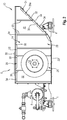
Figur 1 zeigt ein erstes Ausführungsbeispiel des erfindungsgemäßen Kühlmoduls in einer perspektivischen Ansicht. Es hat zwei Querträger 1, die quer zur Fahrtrichtung auf einem Dach eines Schienenfahrzeugs (beide nicht gezeigt) montiert werden. Die Querträger 1 tragen einen Kühler 2, ein Zwischengehäuse 4 und ein Lüfterradgehäuse 6 mit einem Ausblaskanal 10. - Im Betrieb des erfindungsgemäßen Kühlmoduls wird über eine Kühlmittelpumpe 8 Kühlmittel durch den Kühler 2 geführt und von dort in einen Innenraum des Schienenfahrzeugs (beide nicht gezeigt) geführt. Gleichzeitig wird über ein im Innern des Lüfterradgehäuses 6 angeordnetes Radiallüfterrad (vgl.
Figur 2 ) Umgebungsluft durch den Kühler 2 und durch das Zwischengehäuse 4 in das Lüfterradgehäuse 6 gesaugt. Das Radiallüfterrad wird von einem Elektromotor 16 angetrieben. Aus dem Lüfterradgehäuse 6 wird die Umgebungsluft durch den daran gebildeten Ausblaskanal 10 an die Umgebung abgeführt. Damit wird die Umgebungsluft, nach dem sie im Kühler 2 Wärme des zugeführten Kühlmittels aufgenommen hat, durch ein Gehäuse des Kühlmoduls geführt, das im Wesentlichen aus dem Zwischengehäuse 4, dem Lüfterradgehäuse 6 und dem Ausblaskanal 10 besteht. -
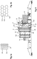
Figur 2 zeigt das Kühlmodul gemäßFigur 1 in einer teilweise geschnittenen seitlichen Ansicht. Über die Kühlmittelpumpe 8 und die beiden geschnitten dargestellten Querträger 1 hinausgehend ist insbesondere ein Schnitt durch das Lüfterradgehäuse 6 dargestellt. In dem Lüfterradgehäuse 6 ist das Radiallüfterrad 12 benachbart zu einem Wandabschnitt 14 des Lüfterradgehäuses 6 angeordnet. Die Umgebungsluft strömt axial durch zum Radiallüfterrad 12 und verlässt dieses radial. - Der Wandabschnitt 14 ist einstückig mit einem Wandabschnitt des Ausblaskanals 10 gebildet. Weiterhin sind ein Deckel 20 und ein Boden 22 des Lüfterradgehäuses 6 dargestellt, wobei der Boden 22 einstückig mit einem dazu abgewinkelten Boden 24 des Ausblaskanals 10 gebildet ist.
- An dem Deckel 20 des Lüfterradgehäuses 6 und an dem gemeinsamen Wandabschnitt 14 des Lüfterradgehäuses 6 und des Ausblaskanals 10 und an dem Boden 24 des Ausblaskanals 10 ist jeweils ein mikro-perforierter Absorber 28 befestigt, wobei die Absorber 28 des Deckels 20 und des Bodens 24 geschnitten dargestellt sind, während der Absorber 28 des Wandabschnitts 14 in einer Ansicht dargestellt ist. Die Absorber 28 sind aus Aluminiumblech hergestellt und sind mehrfach nach einem regelmäßigen Schema abgewinkelt. Durch die Abwinkelungen hat jeder Absorber 28 streifenförmige am Lüfterradgehäuse 6 befestigte Anlageabschnitte 30, die im Wesentlichen flächig am Wandabschnitt 14 bzw. am Boden 24 bzw. am Deckel 20 anliegen. Dazu benachbart sind streifenförmige Abschnitte geformt, zwischen denen jeweils ein als inneres flächiges Element ausgeführter Hauptabschnitt 32 des Absorbers 28 angeordnet ist. Die Hauptabschnitte 32 sind vorzugsweise parallel zum Wandabschnitt 14 bzw. zum Boden 24 bzw. zum Deckel 20 angeordnet. Dadurch entstehen mehrere flache Räume 34, die lediglich über eine Vielzahl von Mikroschlitzen, die die Absorber 28 durchdringen, mit dem Innenraum des Gehäuses 6 verbunden sind.
-
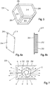
Figuren 3a und 3b zeigen jeweils ein Ausführungsbeispiel von regelmäßigen Strukturen aus Trennwänden 35; 135, die im Innern der Räume 34 aufgestellt sind, um voneinander getrennte Kammern 36; 136 zu bilden. Genauer gesagt hat das erste Ausführungsbeispiel gitterartige Trennwände 35, während die Trennwände des zweiten Ausführungsbeispiels derart angeordnet sind, dass sich wabenartige Kammern 136 ergeben. Bei beiden Ausführungsbeispielen entspricht die Höhe der Trennwände 35; 135 und damit der Kammern 36; 136 der Höhe der Räume 34, die durch den Abstand der Hauptabschnitte 32 der Absorber 28 vom äußeren Wandabschnitt 14 bzw. vom Boden 24 bzw. vom Deckel 20 definiert ist. Damit sind Kammern gebildet, deren Größe in Abhängigkeit der zu dämpfenden Schallfrequenz ausgelegt ist. -
Figur 4 zeigt ein zweites Ausführungsbeispiel des erfindungsgemäßen Kühlmoduls in einer teilweise geschnittenen Ansicht. Das Kühlmodul hat zusätzlich zum ersten Kühler 2 gemäß dem vorhergehenden Ausführungsbeispiel einen zweiten Kühler 102, der von der einströmenden Umgebungsluft (inFigur 4 von links nach rechts) durchströmt wird, bevor sie den ersten Kühler 2, das Zwischengehäuse 4 und das Lüfterradgehäuse 6 durchströmt. Weiterhin hat das zweite Ausführungsbeispiel einen Kühlmittelfilter 144. - In
Figur 4 ist dargestellt, dass die Absorber 28 über ihre Anlageabschnitte 30 und über Einnietmuttern 146 am jeweiligen Gehäuse 4, 6 befestigt sind. Dazu durchdringen die Einnietmuttern 146 die betroffenen Wände und Böden und Decken der Gehäuse 4, 6. Einige Wandabschnitte der Gehäuse 4, 6 weisen an ihrer Innenseite die Absorber 28 auf, durch welche die Räume 34 gebildet sind, in die erfindungsgemäß gitterartige oder wabenartige regelmäßige Strukturen aus Trennwänden zur Kammerbildung eingepasst sind. -
Figur 5 zeigt ein Gehäuse 206 eines dritten Ausführungsbeispiels des erfindungsgemäßen Kühlmoduls in einer schematischen perspektivischen Ansicht. Es ist als Rahmenkonstruktion ausgeführt und hat entlang seinen Kanten Profile 248. In die Bereiche zwischen den Profilen 248 ist jeweils ein flächiger passgenauer Wandabschnitt 214 eingesetzt. -
Figuren 6a und 6b zeigen einen Wandabschnitt 214 des dritten Ausführungsbeispiels gemäßFigur 5 . Genauer gesagt zeigtFigur 6a den Wandabschnitt in einer perspektivischen Ansicht, währendFigur 6b den Wandabschnitt 214 in einer seitlichen geschnitten Darstellung zeigt. Die Wandabschnitte sind aus drei flächigen Wandelementen von mikro-perforierten Absorbern 28 gebildet, also von einem inneren Wandelement 250, einem mittleren Wandelement 252 und einem äußeren Wandelement 254. Dazwischen sind zwei Ebenen bzw. Räume 34 gebildet, in denen Trennwände 35; 135 und Kammern 36; 136 (zum Beispiel nach einem der Ausführungsbeispiele gemäß denFiguren 3a oder 3b ) angeordnet sind. - Die Trennwände 35; 135 sind an den Wandelementen 250, 252, 254 befestigt, so dass die Kammern 36; 136 - abgesehen von den als Mikroschlitze ausgeführten Perforationen - luftdicht sind.
- Das äußere Wandelement 254 hat Löcher 256, über die es auf Stifte 258 der Profile 248 aufgesteckt ist.
-
Figur 7 zeigt das dritte Ausführungsbeispiel des Kühlmoduls gemäß denFiguren 5 und 6 in einer schematischen geschnittenen Darstellung. Es ist dargestellt, dass das Radiallüfterrad 12 die Umgebungsluft radial nach außen fördert. Dabei dringt ein Teil der Umgebungsluft gemäß den Pfeilen durch die Mikroschlitze von drei zusätzlichen am Umfang des Radiallüfterrades 12 verteilten Absorberelementen 218 und von drei Wandelementen 250, 252, 254. Der weitaus größere Teil der Umgebungsluft wird über den Ausblaskanal 10 (vergleicheFigur 1 ) nach außen gefördert. - Offenbart ist ein Kühlmodul mit einem Gehäuse und mit einem Radiallüfterrad, das als Lüfter für einen Kühler dient. Das Gehäuse weist zur Schalldämmung einen aus einem Aluminiumblech umgeformten Absorber auf, der eine Vielzahl von Mikroschlitzen hat. Mit dem Absorber sind Innenwandungen des Gehäuses ganz oder teilweise ausgekleidet, wodurch Räume zwischen der Innenwandung und dem Absorber gebildet sind, die durch wabenförmige oder gitterförmige Trennwände in Kammern unterteilt sind. Die Kammern sind damit nur durch die Mikroschlitze mit dem Innenraum des Gehäuses verbunden und dämmen den Schall des Radiallüfterrads. Alternativ kann auch die äußere Gehäusewand von einem Absorber gebildet sein, der eine Vielzahl von Mikroschlitzen hat.
-
- 1
- Querträger
- 2; 102
- Kühler
- 4
- Zwischengehäuse
- 6
- Lüfterradgehäuse
- 8
- Kühlmittelpumpe
- 10
- Ausblaskanal
- 12
- Radiallüfterrad
- 14; 214
- Wandabschnitt
- 16
- Elektromotor
- 20
- Deckel
- 22
- Boden
- 24
- Boden
- 28
- Absorber
- 30
- Anlageabschnitt
- 32
- Hauptabschnitt / inneres flächiges Wandelement
- 34
- Raum
- 35; 135
- Trennwand
- 36; 136
- Kammer
- 40
- Deckel
- 144
- Kühlmittelfilter
- 146
- Einnietmutter
- 206
- Gehäuse
- 218
- Absorberelement
- 248
- Profil
- 250
- inneres Wandelement
- 252
- mittleres Wandelement
- 254
- äußeres Wandelement
- 256
- Loch
- 258
- Stift
Claims (12)
- Kühlmodul mit einem Lüfterrad (12) und mit einem Gehäuse (4, 6, 10; 206), wobei zur Schalldämmung zumindest ein Wandabschnitt (14, 20, 24, 40; 214) des Gehäuses (4, 6, 10; 206) Kammern (36; 136) aufweist, die von einem sich über mehrere Kammern (36; 136) erstreckenden mikro-perforierten Absorber (28) und von Trennwänden (35; 135) begrenzt sind, wobei der mikro-perforierte Absorber (28) eine Vielzahl von vergleichsweise kleinen Durchgangsausnehmungen hat, und wobei die Kammern (36; 136) durch die Trennwände (35; 135) voneinander getrennt sind, wobei der Absorber (28) einstückig ist, dadurch gekennzeichnet, dass der Absorber (28) mehrere innere flächige Wandelemente (32) bildet und dazwischen Anlageabschnitte (30) in Anlage an einem äußeren flächigen Wandelement aufweist, wobei der Absorber (28) aus einem Blech umgeformt ist und mehrere zueinander parallele Biegestellen hat.
- Kühlmodul nach Anspruch 1, wobei das äußere Wandelement geschlossen ist.
- Kühlmodul nach Anspruch 1, wobei das äußere Wandelement (254) von einem mikro-perforierten Absorber (28) gebildet ist.
- Kühlmodul nach einem der Ansprüche 2 bis 3, wobei der Wandabschnitt (214) ein oder mehrere mittlere flächige Wandelemente (252) aufweist.
- Kühlmodul nach einem der Ansprüche 2 bis 4, wobei die Trennwände (35; 135) zwischen den Wandelementen (250, 252, 254) und senkrecht dazu angeordnet sind.
- Kühlmodul nach einem der vorhergehenden Ansprüche, wobei die Trennwände (35; 135) eine Wabenstruktur oder eine Gitterstruktur bilden.
- Kühlmodul nach einem der Ansprüche 2 bis 6, wobei die Trennwände (35; 135) fest mit den Wandelementen (250, 252, 254) verbunden sind.
- Kühlmodul nach einem der vorhergehenden Ansprüche, wobei das Gehäuse (206) eine Rahmenstruktur hat, in die der Wandabschnitt (214) eingesetzt ist.
- Kühlmodul nach einem der vorhergehenden Ansprüche, wobei das Lüfterrad (12) ein Radialgebläse bildet.
- Kühlmodul nach Anspruch 9, wobei am Umfang des Lüfterrades (12) weitere mikro-perforierte Absorberelemente (218) angeordnet sind, die einen spezifischen Winkel und Radialabstand zum Lüfterrad (12) haben.
- Kühlmodul nach einem der vorhergehenden Ansprüche, wobei der Wandabschnitt (14, 20, 24, 40; 214) parallel zu einem Luftstrom angeordnet ist.
- Kühlmodul nach einem der vorhergehenden Ansprüche mit einem weiteren Lüfterrad, wobei der Wandabschnitt zwischen dem Lüfterrad (12) und dem weiteren Lüfterrad angeordnet ist.
Applications Claiming Priority (1)
| Application Number | Priority Date | Filing Date | Title |
|---|---|---|---|
| DE102014201058.6A DE102014201058A1 (de) | 2014-01-22 | 2014-01-22 | Kühlmodul |
Publications (2)
| Publication Number | Publication Date |
|---|---|
| EP2899406A1 EP2899406A1 (de) | 2015-07-29 |
| EP2899406B1 true EP2899406B1 (de) | 2021-01-06 |
Family
ID=52339003
Family Applications (1)
| Application Number | Title | Priority Date | Filing Date |
|---|---|---|---|
| EP15150394.3A Not-in-force EP2899406B1 (de) | 2014-01-22 | 2015-01-08 | Kühlmodul mit schallgedämmtem gebläse |
Country Status (3)
| Country | Link |
|---|---|
| EP (1) | EP2899406B1 (de) |
| CN (1) | CN104791304B (de) |
| DE (1) | DE102014201058A1 (de) |
Families Citing this family (2)
| Publication number | Priority date | Publication date | Assignee | Title |
|---|---|---|---|---|
| DE102017205083A1 (de) | 2017-03-27 | 2018-09-27 | Robert Bosch Gmbh | Düse und Kühlaggregat |
| CN117927489B (zh) * | 2024-03-21 | 2024-06-18 | 浙江白马科技有限公司 | 花园鼓风机 |
Family Cites Families (6)
| Publication number | Priority date | Publication date | Assignee | Title |
|---|---|---|---|---|
| US4174020A (en) * | 1975-07-01 | 1979-11-13 | Challis Louis A | Acoustic treatment for fans |
| JP2008255969A (ja) * | 2007-04-09 | 2008-10-23 | Kobe Steel Ltd | ファン装置の騒音低減構造 |
| CN201461536U (zh) * | 2008-12-24 | 2010-05-12 | 中国北车集团大连机车研究所有限公司 | 电动车组集成式冷却模块用无蜗壳离心风机组 |
| DE102010061994A1 (de) * | 2010-11-25 | 2012-05-31 | Gardner Denver Deutschland Gmbh | Gebläse-Anordnung |
| US9388731B2 (en) * | 2013-03-15 | 2016-07-12 | Kohler Co. | Noise suppression system |
| CN103362870A (zh) * | 2013-07-02 | 2013-10-23 | 西安交通大学 | 一种吸声蜗壳低噪声离心风机 |
-
2014
- 2014-01-22 DE DE102014201058.6A patent/DE102014201058A1/de not_active Withdrawn
-
2015
- 2015-01-08 EP EP15150394.3A patent/EP2899406B1/de not_active Not-in-force
- 2015-01-21 CN CN201510172631.6A patent/CN104791304B/zh not_active Expired - Fee Related
Non-Patent Citations (1)
| Title |
|---|
| None * |
Also Published As
| Publication number | Publication date |
|---|---|
| CN104791304B (zh) | 2020-09-11 |
| EP2899406A1 (de) | 2015-07-29 |
| CN104791304A (zh) | 2015-07-22 |
| DE102014201058A1 (de) | 2015-07-23 |
Similar Documents
| Publication | Publication Date | Title |
|---|---|---|
| DE102015213470B4 (de) | Lüfterbaustein | |
| DE102016007205A1 (de) | Ventilatoreinheit | |
| DE102014003608A1 (de) | Filtermodul für einen Farbnebelabscheider | |
| CH662623A5 (de) | Einbaurahmen fuer einen ventilator. | |
| EP1895166B1 (de) | Strömungsgleichrichter für einen Ventilator | |
| WO2017032434A1 (de) | Bodenstation zum induktiven laden eines kraftfahrzeugs | |
| EP2574794B1 (de) | Lüftungsbauteil | |
| EP2899406A1 (de) | Kühlmodul mit schallgedämmtem gebläse | |
| DE102019208437A1 (de) | Ventilatoreinrichtung | |
| WO2013174839A1 (de) | Einbaurahmen für wärmeübertrager | |
| DE3210164C2 (de) | Vorrichtung zum Befestigen eines Lüfters in einer Gehäusewand eines elektrischen Gerätes | |
| DE102009006674A1 (de) | Kondensatorvorrichtung für eine Kühlanlage | |
| EP2299194A2 (de) | System, bestehend aus einem Gehäuse, aus zumindest einem in dem Gehäuse befindlichen flächigen Zwischenelement, insbesondere Zwischenboden, sowie aus einem Gehäusedeckel zum Verschließen des Gehäuses sowie Verfahren zur Herstellung | |
| DE102016117380A1 (de) | Schaltschrankkühlgerät mit einem Kondensatabscheider | |
| DE102014018600A1 (de) | Wärmepumpe mit einem Lamellenrohr-Wärmeübertrager und Lamellenrohr-Wärmeübertrager | |
| DE102012019667A1 (de) | Kühlmodul | |
| WO2024046785A1 (de) | Klimagerät | |
| DE102010008396A1 (de) | Wärmetauscher | |
| DE102011015859A1 (de) | Selbsttragendes Kühlmodul | |
| EP3499046B1 (de) | Verfahren zur herstellung eines gebläsegehäuses | |
| DE2612455C2 (de) | Mit einer schalldämmenden Einrichtung versehener Kühlturm | |
| DE102012100038B4 (de) | Elektromotor | |
| EP3770510B1 (de) | Gebläse für eine dunstabzugsvorrichtung und kombinationsgerät | |
| DE202025105466U1 (de) | Zentrifugalbelüftungsventilator | |
| DE10316431B4 (de) | Klimaeinrichtung ausgebildet als dezentrales Gerät |
Legal Events
| Date | Code | Title | Description |
|---|---|---|---|
| PUAI | Public reference made under article 153(3) epc to a published international application that has entered the european phase |
Free format text: ORIGINAL CODE: 0009012 |
|
| 17P | Request for examination filed |
Effective date: 20150108 |
|
| AK | Designated contracting states |
Kind code of ref document: A1 Designated state(s): AL AT BE BG CH CY CZ DE DK EE ES FI FR GB GR HR HU IE IS IT LI LT LU LV MC MK MT NL NO PL PT RO RS SE SI SK SM TR |
|
| AX | Request for extension of the european patent |
Extension state: BA ME |
|
| 17P | Request for examination filed |
Effective date: 20160129 |
|
| RBV | Designated contracting states (corrected) |
Designated state(s): AL AT BE BG CH CY CZ DE DK EE ES FI FR GB GR HR HU IE IS IT LI LT LU LV MC MK MT NL NO PL PT RO RS SE SI SK SM TR |
|
| STAA | Information on the status of an ep patent application or granted ep patent |
Free format text: STATUS: EXAMINATION IS IN PROGRESS |
|
| 17Q | First examination report despatched |
Effective date: 20171116 |
|
| RAP1 | Party data changed (applicant data changed or rights of an application transferred) |
Owner name: ROBERT BOSCH GMBH |
|
| GRAP | Despatch of communication of intention to grant a patent |
Free format text: ORIGINAL CODE: EPIDOSNIGR1 |
|
| STAA | Information on the status of an ep patent application or granted ep patent |
Free format text: STATUS: GRANT OF PATENT IS INTENDED |
|
| INTG | Intention to grant announced |
Effective date: 20200908 |
|
| GRAS | Grant fee paid |
Free format text: ORIGINAL CODE: EPIDOSNIGR3 |
|
| GRAA | (expected) grant |
Free format text: ORIGINAL CODE: 0009210 |
|
| STAA | Information on the status of an ep patent application or granted ep patent |
Free format text: STATUS: THE PATENT HAS BEEN GRANTED |
|
| AK | Designated contracting states |
Kind code of ref document: B1 Designated state(s): AL AT BE BG CH CY CZ DE DK EE ES FI FR GB GR HR HU IE IS IT LI LT LU LV MC MK MT NL NO PL PT RO RS SE SI SK SM TR |
|
| REG | Reference to a national code |
Ref country code: GB Ref legal event code: FG4D Free format text: NOT ENGLISH |
|
| REG | Reference to a national code |
Ref country code: AT Ref legal event code: REF Ref document number: 1352670 Country of ref document: AT Kind code of ref document: T Effective date: 20210115 Ref country code: CH Ref legal event code: EP |
|
| REG | Reference to a national code |
Ref country code: DE Ref legal event code: R096 Ref document number: 502015014103 Country of ref document: DE |
|
| REG | Reference to a national code |
Ref country code: IE Ref legal event code: FG4D Free format text: LANGUAGE OF EP DOCUMENT: GERMAN |
|
| REG | Reference to a national code |
Ref country code: NL Ref legal event code: MP Effective date: 20210106 |
|
| REG | Reference to a national code |
Ref country code: LT Ref legal event code: MG9D |
|
| PG25 | Lapsed in a contracting state [announced via postgrant information from national office to epo] |
Ref country code: PT Free format text: LAPSE BECAUSE OF FAILURE TO SUBMIT A TRANSLATION OF THE DESCRIPTION OR TO PAY THE FEE WITHIN THE PRESCRIBED TIME-LIMIT Effective date: 20210506 Ref country code: LT Free format text: LAPSE BECAUSE OF FAILURE TO SUBMIT A TRANSLATION OF THE DESCRIPTION OR TO PAY THE FEE WITHIN THE PRESCRIBED TIME-LIMIT Effective date: 20210106 Ref country code: HR Free format text: LAPSE BECAUSE OF FAILURE TO SUBMIT A TRANSLATION OF THE DESCRIPTION OR TO PAY THE FEE WITHIN THE PRESCRIBED TIME-LIMIT Effective date: 20210106 Ref country code: GR Free format text: LAPSE BECAUSE OF FAILURE TO SUBMIT A TRANSLATION OF THE DESCRIPTION OR TO PAY THE FEE WITHIN THE PRESCRIBED TIME-LIMIT Effective date: 20210407 Ref country code: FI Free format text: LAPSE BECAUSE OF FAILURE TO SUBMIT A TRANSLATION OF THE DESCRIPTION OR TO PAY THE FEE WITHIN THE PRESCRIBED TIME-LIMIT Effective date: 20210106 Ref country code: BG Free format text: LAPSE BECAUSE OF FAILURE TO SUBMIT A TRANSLATION OF THE DESCRIPTION OR TO PAY THE FEE WITHIN THE PRESCRIBED TIME-LIMIT Effective date: 20210406 Ref country code: NL Free format text: LAPSE BECAUSE OF FAILURE TO SUBMIT A TRANSLATION OF THE DESCRIPTION OR TO PAY THE FEE WITHIN THE PRESCRIBED TIME-LIMIT Effective date: 20210106 Ref country code: NO Free format text: LAPSE BECAUSE OF FAILURE TO SUBMIT A TRANSLATION OF THE DESCRIPTION OR TO PAY THE FEE WITHIN THE PRESCRIBED TIME-LIMIT Effective date: 20210406 |
|
| PG25 | Lapsed in a contracting state [announced via postgrant information from national office to epo] |
Ref country code: LV Free format text: LAPSE BECAUSE OF FAILURE TO SUBMIT A TRANSLATION OF THE DESCRIPTION OR TO PAY THE FEE WITHIN THE PRESCRIBED TIME-LIMIT Effective date: 20210106 Ref country code: RS Free format text: LAPSE BECAUSE OF FAILURE TO SUBMIT A TRANSLATION OF THE DESCRIPTION OR TO PAY THE FEE WITHIN THE PRESCRIBED TIME-LIMIT Effective date: 20210106 Ref country code: PL Free format text: LAPSE BECAUSE OF FAILURE TO SUBMIT A TRANSLATION OF THE DESCRIPTION OR TO PAY THE FEE WITHIN THE PRESCRIBED TIME-LIMIT Effective date: 20210106 Ref country code: SE Free format text: LAPSE BECAUSE OF FAILURE TO SUBMIT A TRANSLATION OF THE DESCRIPTION OR TO PAY THE FEE WITHIN THE PRESCRIBED TIME-LIMIT Effective date: 20210106 |
|
| REG | Reference to a national code |
Ref country code: CH Ref legal event code: PL |
|
| PG25 | Lapsed in a contracting state [announced via postgrant information from national office to epo] |
Ref country code: IS Free format text: LAPSE BECAUSE OF FAILURE TO SUBMIT A TRANSLATION OF THE DESCRIPTION OR TO PAY THE FEE WITHIN THE PRESCRIBED TIME-LIMIT Effective date: 20210506 Ref country code: LU Free format text: LAPSE BECAUSE OF NON-PAYMENT OF DUE FEES Effective date: 20210108 |
|
| REG | Reference to a national code |
Ref country code: BE Ref legal event code: MM Effective date: 20210131 |
|
| REG | Reference to a national code |
Ref country code: DE Ref legal event code: R097 Ref document number: 502015014103 Country of ref document: DE |
|
| PG25 | Lapsed in a contracting state [announced via postgrant information from national office to epo] |
Ref country code: EE Free format text: LAPSE BECAUSE OF FAILURE TO SUBMIT A TRANSLATION OF THE DESCRIPTION OR TO PAY THE FEE WITHIN THE PRESCRIBED TIME-LIMIT Effective date: 20210106 Ref country code: CZ Free format text: LAPSE BECAUSE OF FAILURE TO SUBMIT A TRANSLATION OF THE DESCRIPTION OR TO PAY THE FEE WITHIN THE PRESCRIBED TIME-LIMIT Effective date: 20210106 Ref country code: MC Free format text: LAPSE BECAUSE OF FAILURE TO SUBMIT A TRANSLATION OF THE DESCRIPTION OR TO PAY THE FEE WITHIN THE PRESCRIBED TIME-LIMIT Effective date: 20210106 Ref country code: SM Free format text: LAPSE BECAUSE OF FAILURE TO SUBMIT A TRANSLATION OF THE DESCRIPTION OR TO PAY THE FEE WITHIN THE PRESCRIBED TIME-LIMIT Effective date: 20210106 |
|
| PLBE | No opposition filed within time limit |
Free format text: ORIGINAL CODE: 0009261 |
|
| STAA | Information on the status of an ep patent application or granted ep patent |
Free format text: STATUS: NO OPPOSITION FILED WITHIN TIME LIMIT |
|
| PG25 | Lapsed in a contracting state [announced via postgrant information from national office to epo] |
Ref country code: SK Free format text: LAPSE BECAUSE OF FAILURE TO SUBMIT A TRANSLATION OF THE DESCRIPTION OR TO PAY THE FEE WITHIN THE PRESCRIBED TIME-LIMIT Effective date: 20210106 Ref country code: RO Free format text: LAPSE BECAUSE OF FAILURE TO SUBMIT A TRANSLATION OF THE DESCRIPTION OR TO PAY THE FEE WITHIN THE PRESCRIBED TIME-LIMIT Effective date: 20210106 Ref country code: DK Free format text: LAPSE BECAUSE OF FAILURE TO SUBMIT A TRANSLATION OF THE DESCRIPTION OR TO PAY THE FEE WITHIN THE PRESCRIBED TIME-LIMIT Effective date: 20210106 Ref country code: ES Free format text: LAPSE BECAUSE OF FAILURE TO SUBMIT A TRANSLATION OF THE DESCRIPTION OR TO PAY THE FEE WITHIN THE PRESCRIBED TIME-LIMIT Effective date: 20210106 Ref country code: CH Free format text: LAPSE BECAUSE OF NON-PAYMENT OF DUE FEES Effective date: 20210131 Ref country code: LI Free format text: LAPSE BECAUSE OF NON-PAYMENT OF DUE FEES Effective date: 20210131 |
|
| 26N | No opposition filed |
Effective date: 20211007 |
|
| GBPC | Gb: european patent ceased through non-payment of renewal fee |
Effective date: 20210406 |
|
| PG25 | Lapsed in a contracting state [announced via postgrant information from national office to epo] |
Ref country code: AL Free format text: LAPSE BECAUSE OF FAILURE TO SUBMIT A TRANSLATION OF THE DESCRIPTION OR TO PAY THE FEE WITHIN THE PRESCRIBED TIME-LIMIT Effective date: 20210106 Ref country code: FR Free format text: LAPSE BECAUSE OF NON-PAYMENT OF DUE FEES Effective date: 20210306 Ref country code: GB Free format text: LAPSE BECAUSE OF NON-PAYMENT OF DUE FEES Effective date: 20210406 Ref country code: IE Free format text: LAPSE BECAUSE OF NON-PAYMENT OF DUE FEES Effective date: 20210108 |
|
| PG25 | Lapsed in a contracting state [announced via postgrant information from national office to epo] |
Ref country code: SI Free format text: LAPSE BECAUSE OF FAILURE TO SUBMIT A TRANSLATION OF THE DESCRIPTION OR TO PAY THE FEE WITHIN THE PRESCRIBED TIME-LIMIT Effective date: 20210106 |
|
| REG | Reference to a national code |
Ref country code: AT Ref legal event code: MM01 Ref document number: 1352670 Country of ref document: AT Kind code of ref document: T Effective date: 20210108 |
|
| PG25 | Lapsed in a contracting state [announced via postgrant information from national office to epo] |
Ref country code: IT Free format text: LAPSE BECAUSE OF FAILURE TO SUBMIT A TRANSLATION OF THE DESCRIPTION OR TO PAY THE FEE WITHIN THE PRESCRIBED TIME-LIMIT Effective date: 20210106 Ref country code: AT Free format text: LAPSE BECAUSE OF NON-PAYMENT OF DUE FEES Effective date: 20210108 |
|
| PGFP | Annual fee paid to national office [announced via postgrant information from national office to epo] |
Ref country code: DE Payment date: 20220324 Year of fee payment: 8 |
|
| PG25 | Lapsed in a contracting state [announced via postgrant information from national office to epo] |
Ref country code: IS Free format text: LAPSE BECAUSE OF FAILURE TO SUBMIT A TRANSLATION OF THE DESCRIPTION OR TO PAY THE FEE WITHIN THE PRESCRIBED TIME-LIMIT Effective date: 20210506 |
|
| PG25 | Lapsed in a contracting state [announced via postgrant information from national office to epo] |
Ref country code: BE Free format text: LAPSE BECAUSE OF NON-PAYMENT OF DUE FEES Effective date: 20210131 |
|
| PG25 | Lapsed in a contracting state [announced via postgrant information from national office to epo] |
Ref country code: HU Free format text: LAPSE BECAUSE OF FAILURE TO SUBMIT A TRANSLATION OF THE DESCRIPTION OR TO PAY THE FEE WITHIN THE PRESCRIBED TIME-LIMIT; INVALID AB INITIO Effective date: 20150108 |
|
| PG25 | Lapsed in a contracting state [announced via postgrant information from national office to epo] |
Ref country code: CY Free format text: LAPSE BECAUSE OF FAILURE TO SUBMIT A TRANSLATION OF THE DESCRIPTION OR TO PAY THE FEE WITHIN THE PRESCRIBED TIME-LIMIT Effective date: 20210106 |
|
| REG | Reference to a national code |
Ref country code: DE Ref legal event code: R119 Ref document number: 502015014103 Country of ref document: DE |
|
| PG25 | Lapsed in a contracting state [announced via postgrant information from national office to epo] |
Ref country code: DE Free format text: LAPSE BECAUSE OF NON-PAYMENT OF DUE FEES Effective date: 20230801 |
|
| PG25 | Lapsed in a contracting state [announced via postgrant information from national office to epo] |
Ref country code: MK Free format text: LAPSE BECAUSE OF FAILURE TO SUBMIT A TRANSLATION OF THE DESCRIPTION OR TO PAY THE FEE WITHIN THE PRESCRIBED TIME-LIMIT Effective date: 20210106 |
|
| PG25 | Lapsed in a contracting state [announced via postgrant information from national office to epo] |
Ref country code: TR Free format text: LAPSE BECAUSE OF FAILURE TO SUBMIT A TRANSLATION OF THE DESCRIPTION OR TO PAY THE FEE WITHIN THE PRESCRIBED TIME-LIMIT Effective date: 20210106 |
|
| PG25 | Lapsed in a contracting state [announced via postgrant information from national office to epo] |
Ref country code: MT Free format text: LAPSE BECAUSE OF FAILURE TO SUBMIT A TRANSLATION OF THE DESCRIPTION OR TO PAY THE FEE WITHIN THE PRESCRIBED TIME-LIMIT Effective date: 20210106 |