EP2899331A1 - Perimeterdichtungskomponente und Verfahren zur Herstellung davon - Google Patents
Perimeterdichtungskomponente und Verfahren zur Herstellung davon Download PDFInfo
- Publication number
- EP2899331A1 EP2899331A1 EP14152340.7A EP14152340A EP2899331A1 EP 2899331 A1 EP2899331 A1 EP 2899331A1 EP 14152340 A EP14152340 A EP 14152340A EP 2899331 A1 EP2899331 A1 EP 2899331A1
- Authority
- EP
- European Patent Office
- Prior art keywords
- perimeter
- sealing component
- perimeter sealing
- room
- attached
- Prior art date
- Legal status (The legal status is an assumption and is not a legal conclusion. Google has not performed a legal analysis and makes no representation as to the accuracy of the status listed.)
- Granted
Links
- 238000007789 sealing Methods 0.000 title claims abstract description 102
- 238000000034 method Methods 0.000 title claims description 17
- 238000004519 manufacturing process Methods 0.000 title claims description 6
- 238000009413 insulation Methods 0.000 claims abstract description 45
- 239000012790 adhesive layer Substances 0.000 claims description 13
- 238000005520 cutting process Methods 0.000 claims description 8
- 239000002390 adhesive tape Substances 0.000 claims description 5
- 238000009408 flooring Methods 0.000 claims description 4
- 239000006261 foam material Substances 0.000 claims description 3
- 239000004820 Pressure-sensitive adhesive Substances 0.000 claims description 2
- 238000010276 construction Methods 0.000 description 10
- 239000010410 layer Substances 0.000 description 4
- 230000005540 biological transmission Effects 0.000 description 3
- 239000000463 material Substances 0.000 description 3
- 239000012530 fluid Substances 0.000 description 2
- 238000000926 separation method Methods 0.000 description 2
- 229920005830 Polyurethane Foam Polymers 0.000 description 1
- 239000000853 adhesive Substances 0.000 description 1
- 238000004026 adhesive bonding Methods 0.000 description 1
- 230000009365 direct transmission Effects 0.000 description 1
- 238000010438 heat treatment Methods 0.000 description 1
- 239000011496 polyurethane foam Substances 0.000 description 1
Images


Classifications
-
- E—FIXED CONSTRUCTIONS
- E04—BUILDING
- E04F—FINISHING WORK ON BUILDINGS, e.g. STAIRS, FLOORS
- E04F21/00—Implements for finishing work on buildings
- E04F21/0038—Implements for finishing work on buildings for fitting sealing strips or like
-
- E—FIXED CONSTRUCTIONS
- E04—BUILDING
- E04F—FINISHING WORK ON BUILDINGS, e.g. STAIRS, FLOORS
- E04F15/00—Flooring
- E04F15/02—Flooring or floor layers composed of a number of similar elements
- E04F15/02005—Construction of joints, e.g. dividing strips
-
- E—FIXED CONSTRUCTIONS
- E04—BUILDING
- E04F—FINISHING WORK ON BUILDINGS, e.g. STAIRS, FLOORS
- E04F15/00—Flooring
- E04F15/12—Flooring or floor layers made of masses in situ, e.g. seamless magnesite floors, terrazzo gypsum floors
- E04F15/14—Construction of joints, e.g. dividing strips
-
- E—FIXED CONSTRUCTIONS
- E04—BUILDING
- E04F—FINISHING WORK ON BUILDINGS, e.g. STAIRS, FLOORS
- E04F15/00—Flooring
- E04F15/18—Separately-laid insulating layers; Other additional insulating measures; Floating floors
- E04F15/188—Edge insulation strips, e.g. for floor screed layers
-
- E—FIXED CONSTRUCTIONS
- E04—BUILDING
- E04F—FINISHING WORK ON BUILDINGS, e.g. STAIRS, FLOORS
- E04F15/00—Flooring
- E04F15/18—Separately-laid insulating layers; Other additional insulating measures; Floating floors
- E04F15/20—Separately-laid insulating layers; Other additional insulating measures; Floating floors for sound insulation
-
- E—FIXED CONSTRUCTIONS
- E04—BUILDING
- E04F—FINISHING WORK ON BUILDINGS, e.g. STAIRS, FLOORS
- E04F19/00—Other details of constructional parts for finishing work on buildings
- E04F19/02—Borders; Finishing strips, e.g. beadings; Light coves
- E04F19/04—Borders; Finishing strips, e.g. beadings; Light coves for use between floor or ceiling and wall, e.g. skirtings
- E04F19/0486—Corner filling pieces
Definitions
- the present invention relates to a perimeter sealing component for attaching floor and wall insulations to corners of a room.
- the invention further relates to a method for manufacturing of such a perimeter sealing component.
- floor insulation systems are incorporated into building designs to minimize floor impact noises and airborne sound transmissions. Creating airspace between the structural and isolated floors, while decoupling the two floors, effectively controls noise transmission.
- An optimal sound insulation is achieved when the top floor surface (e.g. the parquet flooring or concrete top layer) is fully isolated from the building structure and non-structural components, such as duct work and piping of an under floor heating.
- perimeter insulation strip In order to improve the sound insulation between the floor and the walls of a building, it is customary to leave a gap between an edge of the floor construction and a perimeter wall, the gap being filled with a so called perimeter insulation strip.
- the material used for the perimeter insulation strip requires being flexible in order to permit an expansion of the floor construction, and thus, flexible foam materials have conventionally been used.
- These flexible perimeter insulating strips conventionally exhibit a single strip, which is arranged along the whole perimeter of a wall.
- a problem arising in connection with the conventional perimeter insulating strips is that the strips have to be bend into the shape of the corners of a room, so as to be arranged along the whole perimeter of the walls. This has been found to cause capillary channels through which concrete can leak from the top floor (i.e. fluid concrete top layer) to the construction floor, resulting in a physical connection between the two layers of the floor. Needless to say that this physical connection between the different layers of the floor construction causes a substantial decrease of the sound insulation of a building, that is of the contact insulation.
- a further object of the present invention is to provide for a perimeter sealing component, which can be installed easily and quickly, without having to bend the perimeter sealing strip around corners of the room.
- the present invention concerns a perimeter sealing component for attaching floor and wall insulations to corners of a room, the perimeter sealing comprising a first portion extending in a first direction, wherein the first portion has a first surface, which is adapted to be attached to a first wall of the room.
- the perimeter sealing component of the present invention further comprises a second portion extending in a second direction, which is different from the first direction.
- the second portion also has a first surface, which is adapted to be attached to a second wall of the room.
- the perimeter sealing component comprises a substantially rigid, predefine shape, which is adapted to cover the corner of the room.
- the present invention relates to a separately fitted perimeter sealing component having a pre-define shape, which fits perfectly into the corner areas of a room.
- the perimeter sealing component of the present invention is furthermore adapted to be attached to floor and wall insulations, as will be described in more detail below.
- the perimeter sealing component comprises a third portion being attached to the first and second portions.
- the third portion is adapted to be attached to a floor of the room.
- the third component may extend substantially horizontally from the first and second portions of the perimeter sealing component, so as to align with the substantially horizontal floor of the respective room.
- substantially horizontal means that the third portion extends in the same direction as the floor of a room, which is frequently far from being perfectly horizontal.
- the third portion of the perimeter sealing component may further be fitted with an adhesive layer, which is disposed on a first surface of the third portion, which is adapted to be in contact with the floor of the room. Therefore, the third portion is preferably self-adhesive, and this easily connectable to the floor construction of a room.
- the first and second portions of the perimeter sealing component are formed as substantially vertical portions.
- substantially vertical refers to the fact that the first and second portions are constructed so as to conform to the walls of a building, which are often far from being perfectly vertical, as has already been described in connection with the substantially horizontal third portion.
- the substantially horizontal first and second portions may have a height of 5 cm to 8 cm, so as to cover the complete height of conventional flooring constructions.
- at least the first and second portions comprise an adhesive layer on their first surfaces. Consequently, the first and second portions can easily be attached to the first and second walls of the room, by means of the adhesive layer.
- the adhesive layer maybe made from a pressure sensitive adhesive such that the inventive perimeter sealing component simply needs to be pushed against the corners of a room in order to obtain a perfect fit.
- the perimeter sealing component further comprises a liner, preferably a cover tape, disposed on top of the adhesive layers. That is, before the perimeter sealing component is attached to the corners of a room, the liner, which protects the adhesive layer during transport, is striped of by the user.
- the perimeter sealing component maybe made of a soft foam material.
- the perimeter sealing component maybe made of polyurethane foam, which was cut and heat-sealed into its pre-defined shape.
- the invented perimeter sealing component is preferably constructed in such a manner that the second direction of the second portion is substantially particular to the first direction of the first portion.
- the second portion is preferably arranged orthogonally to the first portion of the perimeter sealing component.
- the first and second portions can be connected to each other such that two different perimeter sealing components are constructed.
- the first and second portions maybe arranged to each other in such a manner that the perimeter sealing component is adapted to fit into an inner corner or onto an outer corner respectively.
- the present invention further relates to a sound insulation for the flooring area of a room.
- the inventive sound insulation comprises a plurality of floor insulations, wall insulations and at least one inventive perimeter sealing component.
- the wall insulations which can be constructed as perimeter insulating strips, are attached to the at least one perimeter sealing component at at least one corner of the room.
- the inventive sound insulation comprises several perimeter sealing components for each corner the room. Consequently, each piece of wall insulation is attached to two perimeter sealing components at their first and second end portions.
- the wall insulations are attached to the at least one perimeter sealing component by means of at least one adhesive tape.
- the at least one adhesive tape maybe used to attach and cover adjacent edges of the wall insulations and the perimeter sealing component.
- the present invention also relates to a method for manufacturing the inventive perimeter sealing component.
- the method comprises the following steps:
- the inventive perimeter sealing component can be produced from commonly available perimeter insulating strips, which are attached along a miter joint. Therefore, the method of the present invention provides for a simple and cost efficient way of producing the advantageous perimeter sealing components.
- the first and second perimeter insulation strips are connected to each other by means of heat sealing.
- the heat sealing maybe performed for a period of 45 to 60 minutes, so as to provide a mechanically strong and waterproof joint, which prevents undesirable leakage of fluid material there through.
- the cutting angle is chosen to be between 40° and 50° with respect to a longitudinal axis of the first and second strips. Consequently, the first and second strips can be attached to each other at a right angle, so as to fit perfectly into the corners of a room.
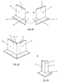
- Figures 1 and 2 show first and second embodiments of the inventive perimeter sealing component 10, 20.
- the first embodiment of the perimeter sealing component 10 is adapted to be attached to an outer corner
- the second embodiment of the perimeter sealing component 20 is adapted to be attached to an inner corner of a room.
- the first and second embodiments of the perimeter sealing component 10, 20 comprise a first portion 11, 21 attached to a second portion 12, 22 along a miter joint 15, 25, after a heat sealing step has been performed.
- the first portion extends in a first direction, which is different from a second direction of the second portion 12, 22.
- each of the first and second portions 11, 21, 12, 22 comprises a first surface, which is adapted to be attached to first or second walls of the room. It should be noted that Figures 1 and 2 only show the second surfaces of the first and second portions 11, 12, 21, 22 which are opposite to the first surfaces thereof.
- the perimeter sealing component comprises a substantially rigid, pre-defined shape, which is adapted to cover a corner of the room.
- first and second portions 11, 12, 21, 22 of the perimeter sealing component 10, 20 are permanently fixed to each other along said miter joint.
- the perimeter sealing components 10, 20 shown in Figures 1 and 2 each comprise a third portion 13, 23, which is attached to the first and second components 11, 12, 21, 22.
- the third component 13, 23 is adapted to be attached to the floor of the room.
- the third portion 13, 23 extends substantially horizontally from the first and the second portions 11, 12, 21, 22 of the perimeter sealing component 10, 20.
- the third portion 13 according to the first embodiment of the perimeter sealing component 10 extends around the first and second portions 11, 12 of the perimeter sealing component 10.
- the third portion 23 of the perimeter sealing component 20 according to the second embodiment extends directly in between the first and second portions 21, 22.
- the perimeter sealing component 10 of the first embodiment is configured to fit an outer corner
- the perimeter sealing component 20 of the second embodiment is configured to fit an inner corner of the room.
- the first and second portions are constructed as substantially vertical portions, preferably with a height of 5 cm to 8 cm.
- the height and direction of the first and second portions 11, 20, 21, 22 are adapted to the particular circumstances of the floor construction.
- Figures 1 and 2 further show that at least the first and second portions 11, 12, 21, 22 may comprise an adhesive layer 14, 24 on their respective first surfaces.
- the perimeter sealing component may comprise a liner, preferably a cover paper, which is disposed over the adhesive layer 14, 24.
- Fig. 3a shows a perimeter insulating structure 100, which comprises a plurality, here three, wall insulations represented by perimeter insulating strips 30, which are connected to a perimeter sealing component 10 according to the first embodiment shown in Fig. 1 and a perimeter sealing component 20 according to the second embodiment showing in Fig. 2 respectively.
- each of the perimeter insulating strips 30 comprises a first portion 31, which is a substantially vertical portion adapted to be attached to the perimeter wall of a room and a second portion 32, which is a substantially horizontally portion adapted to be attached to the floor of a room.
- the conventionally known perimeter insulating strips 30 can easily be attached to side edges 17, 18, 27, 28 of the inventive perimeter sealing component 10 or 20 respectively. Due to the construction of the novel perimeter sealing components 10, 20 of the present invention, the perimeter insulating strips 30 do not to have to be bent around the corners of a room anymore. Rather, the perimeter insulating strips 30 can conveniently be arranged along the straight parts of the perimeter wall. The corners, on the other hand, are reliably covered by the inventive perimeter sealing components 10, 20.
- Fig. 3b shows one embodiment of the inventive sound insulation 200, which comprises a plurality of floor insulations 40, wall insulation (insulating strips 30) and at least one perimeter sealing component 10 or 20 respectively.
- the perimeter insulating strips 30 are attached along their side edges to the inventive perimeters sealing components 10 or 20 respectively, whereas their bottom edges are connected to the floor insulations 40.
- the wall insulations 30 are connected to the perimeter sealing components 10, 20 and the plurality of floor insulations 40 by means of several adhesive tapes 50.
- any other suitable means such as gluing.
- first and second perimeter insulation strips 60, 70 are provided, as can be derived from Fig. 4a .
- the first and second perimeter insulating strips 60, 70 may be conventional perimeter insulating strips as shown by reference sign "30" in Figures 3a and 3b .
- Fig. 4a shows that each of the first and second perimeter insulating strips 60, 70 comprises a first portion 61, 71, extending in a substantially vertical direction, and second portions 62, 72, extending in a substantially horizontally direction.
- a second step is also illustrated by Fig. 4a .
- adjacent edges 64, 74 of the first and second perimeter insulating strips 60, 70 are cut at an angle ⁇ / ⁇ relative to a longitudinal axis of the strips 60, 70, wherein the angles ⁇ / ⁇ correspond to the specifice angle of the corner of a room.
- the angles ⁇ , ⁇ correspond to the miter square, which needs to be used in order to fit the perimeter insulating component to the specific corner of the room.
- the angles ⁇ , ⁇ , of the first and second perimeter insulating strips 60, 70 exhibit 45 degrees.
- first and second perimeter insulating strips 60, 70 are connected to each other along their previously cut,adjacent edges 64, 74 in such a way that the first perimeter insulating strip 60 extends in a first direction and the second perimeter insulating strip 70 extends in a second direction, which is different from the first direction.
- first and second directions are defined by the angles ⁇ and ⁇ at which the side edges 64 and 74 are cut in the previous step of the inventive method.
- first and second perimeter insulating strips 60, 70 are connected to each other by means of heat sealing, which is preferably performed for a period of 45 to 60 minutes in order to achieve a sufficiently staple connection of the first and second perimeter insulating strips 60, 70.
- a last step indicated by Fig. 4b , excess portions of the first and second perimeter insulating strips 60, 70 are removed by a vertical cut along cutting lines 81, 82.
- the cutting lines 81, 82 can be distanced differently far from the side edges 64, 74 of the insulating strips 60, 70, thereby producing first and second portions 11, 12 comprising different lengths.
- the insulating strips 60, 70 should be cut along the lines 81, 82 in such a manner that the outer side edges 17, 18 ( Fig. 3a ) are cut at an angle of 90 degrees.
- Figures 4a to 4c describe the method of the present invention in connection with the first embodiment of the inventive perimeter sealing component 10, it is of course also conceivable to produce the perimeter sealing component 20 according to the second embodiment in a similar manner.
- the only difference when producing the perimeter sealing component 20 shown in Fig. 2 is that the angles ⁇ and ⁇ have to be inverted.
- the angles ⁇ and ⁇ where chosen to be about 45 degrees in order to produce the first embodiment of the inventive perimeter sealing component
- the insulating strips have to be cut at angles ⁇ , ⁇ of -45 degrees in order to produce the perimeter sealing component 20 according to the second embodiment.
Landscapes
- Engineering & Computer Science (AREA)
- Architecture (AREA)
- Civil Engineering (AREA)
- Structural Engineering (AREA)
- Building Environments (AREA)
Priority Applications (2)
| Application Number | Priority Date | Filing Date | Title |
|---|---|---|---|
| EP14152340.7A EP2899331B1 (de) | 2014-01-23 | 2014-01-23 | Perimeterdichtungskomponente und Verfahren zur Herstellung davon |
| PCT/US2014/067947 WO2015112258A1 (en) | 2014-01-23 | 2014-12-01 | Perimeter sealing component and method for manufacture thereof |
Applications Claiming Priority (1)
| Application Number | Priority Date | Filing Date | Title |
|---|---|---|---|
| EP14152340.7A EP2899331B1 (de) | 2014-01-23 | 2014-01-23 | Perimeterdichtungskomponente und Verfahren zur Herstellung davon |
Publications (2)
| Publication Number | Publication Date |
|---|---|
| EP2899331A1 true EP2899331A1 (de) | 2015-07-29 |
| EP2899331B1 EP2899331B1 (de) | 2019-07-03 |
Family
ID=50000811
Family Applications (1)
| Application Number | Title | Priority Date | Filing Date |
|---|---|---|---|
| EP14152340.7A Active EP2899331B1 (de) | 2014-01-23 | 2014-01-23 | Perimeterdichtungskomponente und Verfahren zur Herstellung davon |
Country Status (2)
| Country | Link |
|---|---|
| EP (1) | EP2899331B1 (de) |
| WO (1) | WO2015112258A1 (de) |
Cited By (2)
| Publication number | Priority date | Publication date | Assignee | Title |
|---|---|---|---|---|
| BE1024597B1 (nl) * | 2017-02-20 | 2018-04-17 | Isoproc Cvba | Werkwijze voor het plaatsen van een luchtdichte verbinding in de bouw |
| SE2230277A1 (sv) * | 2022-09-05 | 2024-03-06 | Bernt Magnusson | Tätningsmanschett och metod för tätning i våtrum |
Citations (5)
| Publication number | Priority date | Publication date | Assignee | Title |
|---|---|---|---|---|
| DE8327532U1 (de) * | 1983-09-24 | 1984-04-05 | Heuser, Wolfgang, 4703 Bönen | Vorrichtung zur bildung eines definierten abstandes zwischen einer wandecke und fussboden-estrich |
| DE8800696U1 (de) * | 1988-01-21 | 1988-03-31 | Gefinex GmbH, 4803 Steinhagen | Schalldämmrandstreifen für Deckenkonstruktion |
| DE4114125A1 (de) * | 1991-04-30 | 1992-11-05 | Gefinex Gmbh | Kunststoffschaumrandstreifen |
| US6354057B1 (en) * | 1999-03-04 | 2002-03-12 | Michael K. Ploplis | Seamless floor-to-wall baseboard and methods |
| GB2437180A (en) * | 2006-04-13 | 2007-10-17 | Proctor Group Ltd A | Acoustic Flanking Block |
Family Cites Families (1)
| Publication number | Priority date | Publication date | Assignee | Title |
|---|---|---|---|---|
| DE20305171U1 (de) * | 2003-03-31 | 2003-10-30 | BOLTA Industrie- und Bauprofile GmbH, 94513 Schönberg | Hartschaum-Sockelleiste |
-
2014
- 2014-01-23 EP EP14152340.7A patent/EP2899331B1/de active Active
- 2014-12-01 WO PCT/US2014/067947 patent/WO2015112258A1/en active Application Filing
Patent Citations (5)
| Publication number | Priority date | Publication date | Assignee | Title |
|---|---|---|---|---|
| DE8327532U1 (de) * | 1983-09-24 | 1984-04-05 | Heuser, Wolfgang, 4703 Bönen | Vorrichtung zur bildung eines definierten abstandes zwischen einer wandecke und fussboden-estrich |
| DE8800696U1 (de) * | 1988-01-21 | 1988-03-31 | Gefinex GmbH, 4803 Steinhagen | Schalldämmrandstreifen für Deckenkonstruktion |
| DE4114125A1 (de) * | 1991-04-30 | 1992-11-05 | Gefinex Gmbh | Kunststoffschaumrandstreifen |
| US6354057B1 (en) * | 1999-03-04 | 2002-03-12 | Michael K. Ploplis | Seamless floor-to-wall baseboard and methods |
| GB2437180A (en) * | 2006-04-13 | 2007-10-17 | Proctor Group Ltd A | Acoustic Flanking Block |
Cited By (2)
| Publication number | Priority date | Publication date | Assignee | Title |
|---|---|---|---|---|
| BE1024597B1 (nl) * | 2017-02-20 | 2018-04-17 | Isoproc Cvba | Werkwijze voor het plaatsen van een luchtdichte verbinding in de bouw |
| SE2230277A1 (sv) * | 2022-09-05 | 2024-03-06 | Bernt Magnusson | Tätningsmanschett och metod för tätning i våtrum |
Also Published As
| Publication number | Publication date |
|---|---|
| WO2015112258A1 (en) | 2015-07-30 |
| EP2899331B1 (de) | 2019-07-03 |
Similar Documents
| Publication | Publication Date | Title |
|---|---|---|
| JP4573828B2 (ja) | タイル | |
| ES2901441T3 (es) | Procedimiento para el saneamiento y para la reconstrucción de cuartos húmedos | |
| US9523197B2 (en) | Sound dampening wall | |
| US8733057B2 (en) | Basic insulation covering for parquet and laminate floors | |
| US20190376300A1 (en) | Sealing strip for sealing drywall connecting joints | |
| EP2899331A1 (de) | Perimeterdichtungskomponente und Verfahren zur Herstellung davon | |
| JP2019516889A (ja) | 建築部材間の隙間をシールするためのシールテープおよびこのシールテープを製造するための方法 | |
| US20050072083A1 (en) | Method and system for detachably fixing a surface component to a background | |
| EP3208401A1 (de) | System für wärmedämmende und verkleidungswände | |
| WO2013117553A2 (en) | Tile | |
| JP6900238B2 (ja) | 建具 | |
| JP6393605B2 (ja) | 目地構造 | |
| KR101446505B1 (ko) | 복합단열패널 | |
| HU224894B1 (en) | Substrate for sound isolation of floating floors | |
| US20090064620A1 (en) | Tray Ceiling System | |
| JP5171273B2 (ja) | コンクリート外壁の防湿構造 | |
| EP1606473A1 (de) | Bodenplatte mit dichtlippe | |
| JP6512705B2 (ja) | 枠材カバー | |
| JP6422687B2 (ja) | 断熱気密外壁構造 | |
| US9217246B2 (en) | Surface covering foundation | |
| JP6304800B2 (ja) | ドレイン床構造 | |
| JP7306884B2 (ja) | 間仕切壁 | |
| JP2016211144A (ja) | 縦目地構造及び縦目地の施工方法 | |
| JP6471127B2 (ja) | 遮音カバー及び遮音カバーの作製方法 | |
| CA2887732C (en) | Ceiling hatch |
Legal Events
| Date | Code | Title | Description |
|---|---|---|---|
| PUAI | Public reference made under article 153(3) epc to a published international application that has entered the european phase |
Free format text: ORIGINAL CODE: 0009012 |
|
| 17P | Request for examination filed |
Effective date: 20140123 |
|
| AK | Designated contracting states |
Kind code of ref document: A1 Designated state(s): AL AT BE BG CH CY CZ DE DK EE ES FI FR GB GR HR HU IE IS IT LI LT LU LV MC MK MT NL NO PL PT RO RS SE SI SK SM TR |
|
| AX | Request for extension of the european patent |
Extension state: BA ME |
|
| 17P | Request for examination filed |
Effective date: 20160129 |
|
| RBV | Designated contracting states (corrected) |
Designated state(s): AL AT BE BG CH CY CZ DE DK EE ES FI FR GB GR HR HU IE IS IT LI LT LU LV MC MK MT NL NO PL PT RO RS SE SI SK SM TR |
|
| STAA | Information on the status of an ep patent application or granted ep patent |
Free format text: STATUS: EXAMINATION IS IN PROGRESS |
|
| 17Q | First examination report despatched |
Effective date: 20180517 |
|
| GRAP | Despatch of communication of intention to grant a patent |
Free format text: ORIGINAL CODE: EPIDOSNIGR1 |
|
| STAA | Information on the status of an ep patent application or granted ep patent |
Free format text: STATUS: GRANT OF PATENT IS INTENDED |
|
| INTG | Intention to grant announced |
Effective date: 20190103 |
|
| GRAJ | Information related to disapproval of communication of intention to grant by the applicant or resumption of examination proceedings by the epo deleted |
Free format text: ORIGINAL CODE: EPIDOSDIGR1 |
|
| STAA | Information on the status of an ep patent application or granted ep patent |
Free format text: STATUS: EXAMINATION IS IN PROGRESS |
|
| GRAR | Information related to intention to grant a patent recorded |
Free format text: ORIGINAL CODE: EPIDOSNIGR71 |
|
| GRAS | Grant fee paid |
Free format text: ORIGINAL CODE: EPIDOSNIGR3 |
|
| STAA | Information on the status of an ep patent application or granted ep patent |
Free format text: STATUS: GRANT OF PATENT IS INTENDED |
|
| GRAA | (expected) grant |
Free format text: ORIGINAL CODE: 0009210 |
|
| STAA | Information on the status of an ep patent application or granted ep patent |
Free format text: STATUS: THE PATENT HAS BEEN GRANTED |
|
| INTC | Intention to grant announced (deleted) | ||
| AK | Designated contracting states |
Kind code of ref document: B1 Designated state(s): AL AT BE BG CH CY CZ DE DK EE ES FI FR GB GR HR HU IE IS IT LI LT LU LV MC MK MT NL NO PL PT RO RS SE SI SK SM TR |
|
| INTG | Intention to grant announced |
Effective date: 20190528 |
|
| REG | Reference to a national code |
Ref country code: GB Ref legal event code: FG4D |
|
| REG | Reference to a national code |
Ref country code: CH Ref legal event code: EP Ref country code: AT Ref legal event code: REF Ref document number: 1151173 Country of ref document: AT Kind code of ref document: T Effective date: 20190715 |
|
| REG | Reference to a national code |
Ref country code: DE Ref legal event code: R096 Ref document number: 602014049338 Country of ref document: DE |
|
| REG | Reference to a national code |
Ref country code: IE Ref legal event code: FG4D |
|
| REG | Reference to a national code |
Ref country code: NL Ref legal event code: FP |
|
| REG | Reference to a national code |
Ref country code: LT Ref legal event code: MG4D |
|
| REG | Reference to a national code |
Ref country code: AT Ref legal event code: MK05 Ref document number: 1151173 Country of ref document: AT Kind code of ref document: T Effective date: 20190703 |
|
| PG25 | Lapsed in a contracting state [announced via postgrant information from national office to epo] |
Ref country code: CZ Free format text: LAPSE BECAUSE OF FAILURE TO SUBMIT A TRANSLATION OF THE DESCRIPTION OR TO PAY THE FEE WITHIN THE PRESCRIBED TIME-LIMIT Effective date: 20190703 Ref country code: BG Free format text: LAPSE BECAUSE OF FAILURE TO SUBMIT A TRANSLATION OF THE DESCRIPTION OR TO PAY THE FEE WITHIN THE PRESCRIBED TIME-LIMIT Effective date: 20191003 Ref country code: NO Free format text: LAPSE BECAUSE OF FAILURE TO SUBMIT A TRANSLATION OF THE DESCRIPTION OR TO PAY THE FEE WITHIN THE PRESCRIBED TIME-LIMIT Effective date: 20191003 Ref country code: AT Free format text: LAPSE BECAUSE OF FAILURE TO SUBMIT A TRANSLATION OF THE DESCRIPTION OR TO PAY THE FEE WITHIN THE PRESCRIBED TIME-LIMIT Effective date: 20190703 Ref country code: FI Free format text: LAPSE BECAUSE OF FAILURE TO SUBMIT A TRANSLATION OF THE DESCRIPTION OR TO PAY THE FEE WITHIN THE PRESCRIBED TIME-LIMIT Effective date: 20190703 Ref country code: PT Free format text: LAPSE BECAUSE OF FAILURE TO SUBMIT A TRANSLATION OF THE DESCRIPTION OR TO PAY THE FEE WITHIN THE PRESCRIBED TIME-LIMIT Effective date: 20191104 Ref country code: LT Free format text: LAPSE BECAUSE OF FAILURE TO SUBMIT A TRANSLATION OF THE DESCRIPTION OR TO PAY THE FEE WITHIN THE PRESCRIBED TIME-LIMIT Effective date: 20190703 Ref country code: SE Free format text: LAPSE BECAUSE OF FAILURE TO SUBMIT A TRANSLATION OF THE DESCRIPTION OR TO PAY THE FEE WITHIN THE PRESCRIBED TIME-LIMIT Effective date: 20190703 Ref country code: HR Free format text: LAPSE BECAUSE OF FAILURE TO SUBMIT A TRANSLATION OF THE DESCRIPTION OR TO PAY THE FEE WITHIN THE PRESCRIBED TIME-LIMIT Effective date: 20190703 |
|
| PG25 | Lapsed in a contracting state [announced via postgrant information from national office to epo] |
Ref country code: AL Free format text: LAPSE BECAUSE OF FAILURE TO SUBMIT A TRANSLATION OF THE DESCRIPTION OR TO PAY THE FEE WITHIN THE PRESCRIBED TIME-LIMIT Effective date: 20190703 Ref country code: LV Free format text: LAPSE BECAUSE OF FAILURE TO SUBMIT A TRANSLATION OF THE DESCRIPTION OR TO PAY THE FEE WITHIN THE PRESCRIBED TIME-LIMIT Effective date: 20190703 Ref country code: GR Free format text: LAPSE BECAUSE OF FAILURE TO SUBMIT A TRANSLATION OF THE DESCRIPTION OR TO PAY THE FEE WITHIN THE PRESCRIBED TIME-LIMIT Effective date: 20191004 Ref country code: RS Free format text: LAPSE BECAUSE OF FAILURE TO SUBMIT A TRANSLATION OF THE DESCRIPTION OR TO PAY THE FEE WITHIN THE PRESCRIBED TIME-LIMIT Effective date: 20190703 Ref country code: IS Free format text: LAPSE BECAUSE OF FAILURE TO SUBMIT A TRANSLATION OF THE DESCRIPTION OR TO PAY THE FEE WITHIN THE PRESCRIBED TIME-LIMIT Effective date: 20191103 Ref country code: ES Free format text: LAPSE BECAUSE OF FAILURE TO SUBMIT A TRANSLATION OF THE DESCRIPTION OR TO PAY THE FEE WITHIN THE PRESCRIBED TIME-LIMIT Effective date: 20190703 |
|
| PG25 | Lapsed in a contracting state [announced via postgrant information from national office to epo] |
Ref country code: TR Free format text: LAPSE BECAUSE OF FAILURE TO SUBMIT A TRANSLATION OF THE DESCRIPTION OR TO PAY THE FEE WITHIN THE PRESCRIBED TIME-LIMIT Effective date: 20190703 |
|
| PG25 | Lapsed in a contracting state [announced via postgrant information from national office to epo] |
Ref country code: IT Free format text: LAPSE BECAUSE OF FAILURE TO SUBMIT A TRANSLATION OF THE DESCRIPTION OR TO PAY THE FEE WITHIN THE PRESCRIBED TIME-LIMIT Effective date: 20190703 Ref country code: DK Free format text: LAPSE BECAUSE OF FAILURE TO SUBMIT A TRANSLATION OF THE DESCRIPTION OR TO PAY THE FEE WITHIN THE PRESCRIBED TIME-LIMIT Effective date: 20190703 Ref country code: EE Free format text: LAPSE BECAUSE OF FAILURE TO SUBMIT A TRANSLATION OF THE DESCRIPTION OR TO PAY THE FEE WITHIN THE PRESCRIBED TIME-LIMIT Effective date: 20190703 Ref country code: PL Free format text: LAPSE BECAUSE OF FAILURE TO SUBMIT A TRANSLATION OF THE DESCRIPTION OR TO PAY THE FEE WITHIN THE PRESCRIBED TIME-LIMIT Effective date: 20190703 Ref country code: RO Free format text: LAPSE BECAUSE OF FAILURE TO SUBMIT A TRANSLATION OF THE DESCRIPTION OR TO PAY THE FEE WITHIN THE PRESCRIBED TIME-LIMIT Effective date: 20190703 |
|
| PG25 | Lapsed in a contracting state [announced via postgrant information from national office to epo] |
Ref country code: SM Free format text: LAPSE BECAUSE OF FAILURE TO SUBMIT A TRANSLATION OF THE DESCRIPTION OR TO PAY THE FEE WITHIN THE PRESCRIBED TIME-LIMIT Effective date: 20190703 Ref country code: IS Free format text: LAPSE BECAUSE OF FAILURE TO SUBMIT A TRANSLATION OF THE DESCRIPTION OR TO PAY THE FEE WITHIN THE PRESCRIBED TIME-LIMIT Effective date: 20200224 Ref country code: SK Free format text: LAPSE BECAUSE OF FAILURE TO SUBMIT A TRANSLATION OF THE DESCRIPTION OR TO PAY THE FEE WITHIN THE PRESCRIBED TIME-LIMIT Effective date: 20190703 |
|
| REG | Reference to a national code |
Ref country code: DE Ref legal event code: R097 Ref document number: 602014049338 Country of ref document: DE |
|
| PLBE | No opposition filed within time limit |
Free format text: ORIGINAL CODE: 0009261 |
|
| STAA | Information on the status of an ep patent application or granted ep patent |
Free format text: STATUS: NO OPPOSITION FILED WITHIN TIME LIMIT |
|
| PG2D | Information on lapse in contracting state deleted |
Ref country code: IS |
|
| 26N | No opposition filed |
Effective date: 20200603 |
|
| PG25 | Lapsed in a contracting state [announced via postgrant information from national office to epo] |
Ref country code: SI Free format text: LAPSE BECAUSE OF FAILURE TO SUBMIT A TRANSLATION OF THE DESCRIPTION OR TO PAY THE FEE WITHIN THE PRESCRIBED TIME-LIMIT Effective date: 20190703 Ref country code: MC Free format text: LAPSE BECAUSE OF FAILURE TO SUBMIT A TRANSLATION OF THE DESCRIPTION OR TO PAY THE FEE WITHIN THE PRESCRIBED TIME-LIMIT Effective date: 20190703 |
|
| REG | Reference to a national code |
Ref country code: CH Ref legal event code: PL |
|
| GBPC | Gb: european patent ceased through non-payment of renewal fee |
Effective date: 20200123 |
|
| REG | Reference to a national code |
Ref country code: BE Ref legal event code: MM Effective date: 20200131 |
|
| PG25 | Lapsed in a contracting state [announced via postgrant information from national office to epo] |
Ref country code: LU Free format text: LAPSE BECAUSE OF NON-PAYMENT OF DUE FEES Effective date: 20200123 Ref country code: GB Free format text: LAPSE BECAUSE OF NON-PAYMENT OF DUE FEES Effective date: 20200123 Ref country code: FR Free format text: LAPSE BECAUSE OF NON-PAYMENT OF DUE FEES Effective date: 20200131 |
|
| PG25 | Lapsed in a contracting state [announced via postgrant information from national office to epo] |
Ref country code: BE Free format text: LAPSE BECAUSE OF NON-PAYMENT OF DUE FEES Effective date: 20200131 Ref country code: LI Free format text: LAPSE BECAUSE OF NON-PAYMENT OF DUE FEES Effective date: 20200131 Ref country code: CH Free format text: LAPSE BECAUSE OF NON-PAYMENT OF DUE FEES Effective date: 20200131 |
|
| PG25 | Lapsed in a contracting state [announced via postgrant information from national office to epo] |
Ref country code: IE Free format text: LAPSE BECAUSE OF NON-PAYMENT OF DUE FEES Effective date: 20200123 |
|
| PG25 | Lapsed in a contracting state [announced via postgrant information from national office to epo] |
Ref country code: MT Free format text: LAPSE BECAUSE OF FAILURE TO SUBMIT A TRANSLATION OF THE DESCRIPTION OR TO PAY THE FEE WITHIN THE PRESCRIBED TIME-LIMIT Effective date: 20190703 Ref country code: CY Free format text: LAPSE BECAUSE OF FAILURE TO SUBMIT A TRANSLATION OF THE DESCRIPTION OR TO PAY THE FEE WITHIN THE PRESCRIBED TIME-LIMIT Effective date: 20190703 |
|
| PG25 | Lapsed in a contracting state [announced via postgrant information from national office to epo] |
Ref country code: MK Free format text: LAPSE BECAUSE OF FAILURE TO SUBMIT A TRANSLATION OF THE DESCRIPTION OR TO PAY THE FEE WITHIN THE PRESCRIBED TIME-LIMIT Effective date: 20190703 |
|
| P01 | Opt-out of the competence of the unified patent court (upc) registered |
Effective date: 20230606 |
|
| PGFP | Annual fee paid to national office [announced via postgrant information from national office to epo] |
Ref country code: NL Payment date: 20240126 Year of fee payment: 11 |
|
| PGFP | Annual fee paid to national office [announced via postgrant information from national office to epo] |
Ref country code: DE Payment date: 20240129 Year of fee payment: 11 |