EP2898569B1 - Vorrichtung für synthetische bildgebung eines objekts - Google Patents
Vorrichtung für synthetische bildgebung eines objekts Download PDFInfo
- Publication number
- EP2898569B1 EP2898569B1 EP13828894.9A EP13828894A EP2898569B1 EP 2898569 B1 EP2898569 B1 EP 2898569B1 EP 13828894 A EP13828894 A EP 13828894A EP 2898569 B1 EP2898569 B1 EP 2898569B1
- Authority
- EP
- European Patent Office
- Prior art keywords
- unit cell
- array
- transmitter
- elements
- receiver
- Prior art date
- Legal status (The legal status is an assumption and is not a legal conclusion. Google has not performed a legal analysis and makes no representation as to the accuracy of the status listed.)
- Active
Links
Images







Classifications
-
- G—PHYSICS
- G01—MEASURING; TESTING
- G01S—RADIO DIRECTION-FINDING; RADIO NAVIGATION; DETERMINING DISTANCE OR VELOCITY BY USE OF RADIO WAVES; LOCATING OR PRESENCE-DETECTING BY USE OF THE REFLECTION OR RERADIATION OF RADIO WAVES; ANALOGOUS ARRANGEMENTS USING OTHER WAVES
- G01S13/00—Systems using the reflection or reradiation of radio waves, e.g. radar systems; Analogous systems using reflection or reradiation of waves whose nature or wavelength is irrelevant or unspecified
- G01S13/88—Radar or analogous systems specially adapted for specific applications
- G01S13/89—Radar or analogous systems specially adapted for specific applications for mapping or imaging
- G01S13/90—Radar or analogous systems specially adapted for specific applications for mapping or imaging using synthetic aperture techniques, e.g. synthetic aperture radar [SAR] techniques
-
- G—PHYSICS
- G01—MEASURING; TESTING
- G01S—RADIO DIRECTION-FINDING; RADIO NAVIGATION; DETERMINING DISTANCE OR VELOCITY BY USE OF RADIO WAVES; LOCATING OR PRESENCE-DETECTING BY USE OF THE REFLECTION OR RERADIATION OF RADIO WAVES; ANALOGOUS ARRANGEMENTS USING OTHER WAVES
- G01S13/00—Systems using the reflection or reradiation of radio waves, e.g. radar systems; Analogous systems using reflection or reradiation of waves whose nature or wavelength is irrelevant or unspecified
- G01S13/02—Systems using reflection of radio waves, e.g. primary radar systems; Analogous systems
- G01S13/06—Systems determining position data of a target
- G01S13/42—Simultaneous measurement of distance and other co-ordinates
-
- H—ELECTRICITY
- H01—ELECTRIC ELEMENTS
- H01Q—ANTENNAS, i.e. RADIO AERIALS
- H01Q21/00—Antenna arrays or systems
- H01Q21/06—Arrays of individually energised antenna units similarly polarised and spaced apart
- H01Q21/061—Two dimensional planar arrays
Definitions
- This invention relates to synthetic imaging. More specifically, this invention relates to a synthetic imaging apparatus that provides dense uniform sampling and increased imaging performance with low artifact levels for arrays with moderate baseline spacing and fewer numbers of transmitters and/or receivers.
- Microwave and millimeter-wave holographic or synthetic aperture imaging techniques have been developed for a wide variety of applications. These applications include concealed weapon detection, radar cross-section (RCS) imaging, ground penetrating radar (GPR), through-wall and inner wall imaging, and non-destructive evaluation.
- the imaging techniques developed are fully three-dimensional and typically operate by scanning a wide bandwidth radar transceiver over a planar or cylindrical aperture, and using mathematical techniques to focus the data into a three-dimensional image. It is advantageous to use mathematical focusing for these applications because it allows for the use of large apertures and extreme near-field operation, where it would be inconvenient or impossible to use physical focusing elements such as lenses or reflectors. Additionally, scanning the transmitter along with the receiver doubles the resolution relative to fixed transmitters and provides superior illumination quality by using a large diversity of transmitter positions.
- Sequentially-switched linear array technology that allows one dimension of a planar or cylindrical aperture to be effectively scanned electronically at high speed has been developed. This is accomplished by sequencing through each element or transmit and receive pairs using microwave or millimeter-wave switching networks connected to the radar transceiver. Mechanical scanning along the dimension orthogonal to the array axis then completes the sampling of a two-dimensional cylindrical or planar aperture. These data can then be reconstructed using, for example, wideband holographic imaging algorithms.
- each antenna is placed uniformly along the axis of the linear array, and can function simultaneously as a transmitter and receiver.
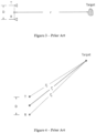
- This scenario is depicted in Figure 1 .
- a switching network is used to sequentially select each antenna element and then use it to transmit and receive the wideband microwave/millimeter-wave signal.
- An antenna spacing of ⁇ results in an effective spatial sample spacing of ⁇ . While conceptually simple, this technique has a number of drawbacks. First, the antennae must be spaced very closely, usually on the order of one-half wavelength ( ⁇ /2) at the center frequency in order to satisfy the spatial sampling criterion on the aperture.
- microwave/millimeter-wave transceiver must be capable of separating the transmit signal from the receive signal. This is possible using directional couplers or circulators, however, these introduce additional losses and do not perfectly isolate the weaker received signal from the much stronger transmitted signal.
- a more practical and effective technique separates the system into two linear arrays.
- One array is dedicated as a transmit array, and the other array is dedicated as a receive array.
- the transmit and receive arrays have an element spacing of 2 ⁇ and are offset from each other by ⁇ as shown in Figure 2 .
- a transmit and receive antenna pair approximately sample the spatial point located half-way between the phase centers of each antenna. This approximation is valid assuming that the transmit-receive antenna spacing is much less than the distance to the scattering target.
- the array is sequentially sampled by switching on the first transmit antenna and the first receive antenna and collecting the first spatial sample.
- the second transmit antenna can then be switched on and the second sample collected (with the first receive antenna still switched on).
- the second receive antenna is then switched on (with the second transmit antenna still on) to collect the third spatial sample. This process is then continued across the array.
- the switching scheme is described in Figure 2 in the following way. Dotted lines are used to indicate individual pairs of transmit/receive antennas and x's are used to indicate the locations of the effective spatial sampling positions.
- This configuration has a number of advantages over the configuration shown in Figure 1 . Antennas are dedicated to be either transmitters or receivers, so no duplexing is required in the transceiver. Antenna spacing of 2 ⁇ results in an effective sample spacing of ⁇ . This allows for larger antennae to be utilized and reduces the coupling between the antennae.
- this design allows amplifiers to be placed within the switching network to compensate for switching losses, which is not readily accomplished if each element must act as both a transmitter and a receiver.
- N spatial samples To acquire N spatial samples requires approximately N antennae total (N/2 transmit and N/2 receive). This sampling technique is very effective and has been incorporated into many systems.
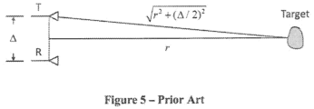
- This error is dependent on the separation of the antennas and the range and position (angle) to the target.
- the target position cannot be known prior to imaging, so this error cannot be completely corrected, however, as described later in this section, the error can be largely removed by approximating the direction of wave propagation as being along the antenna axes.
- this error can be made small, and in the array configuration shown in Figure 2 , this error is insignificant because it is identical for each effective sample location and therefore does not affect focusing. In this case, only a very slight range position error might be observed.
- the sampling technique described above and shown in Figure 2 is very effective, however, it is very desirable to reduce the number of antenna elements required to sample the width/height of the aperture.
- the number of samples needed is determined by Nyquist sampling requirements, however, the number of antenna elements can be reduced using special sampling techniques that exploit the quasi-monostatic approximation by using multiple receivers for each transmitter (or vice-versa).
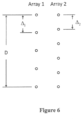
- One sampling technique uses the same configuration as in Figure 2 , except that the receive array has been thinned by removing every other receive antenna element, as shown in Figure 6 .
- Each receiver is now used in conjunction with four nearest transmit antenna elements, as shown in the Figure 6 (dotted lines indicate antenna pairings, and short lines indicate effective sample locations).
- the left and right effective sample columns are offset vertically from each other by ⁇ /2, and laterally by an amount equal to the horizontal spacing of R1/R2 from the transmit array (D). Since a linear mechanical scan is assumed to complete the scanning of the rectilinear or cylindrical aperture, these offset effective sample locations can be made to align at slightly offset times during the mechanical scan.
- the transmit array can be sequenced using the R2 receive array to collect the sample locations shown in the right column, then when the array has moved right a distance D, the transmit array can be sequenced using the R1 receive array to collect the sample locations shown in the left column superimposed over the previously collected samples.
- the effective sample spacing is ⁇ /2.
- the thinned-receiver array and interlaced linear array sampling techniques described above provide a powerful means of reducing the number of antennas needed to uniformly sample a linear axis. This reduction is approximately a factor of 2 for the interlaced technique. While powerful, this technique has two primary limitations. First the reduction in the antennas needed is limited. Additional thinning of the receive arrays can reduce this somewhat, however, the transmit array needs to maintain a spacing of 2 ⁇ for effective sampling of ⁇ /2, which limits the reduction in the number of antennas. The technique does not provide a systematic way to continue to reduce the number of antennas required to densely sample the array axis. An additional concern in some cases is that the technique uses two effective or virtual columns, and relies on mechanical motion to overlay the two sample columns.
- US 2011/063158 A1 discloses an array antenna apparatus and radar apparatus, including a transmission-side directivity control which controls a directivity of the transmission array antenna by controlling phases of the transmit antenna elements, and a receiver-side directivity control which controls a directivity of the receive array antenna by controlling phases of the reception antenna elements.
- US 2008/100510 A1 discloses an antennae system for a detector, including a two-dimensional transmitter array and a two-dimensional receiver array.
- US 2012/105268 A1 discloses a method of detecting a scatterer in a structure by transmitting signals from multiple positions and receiving reflected signals at one or a multiple number of positions.
- US 2011/0140949 A1 discloses a multiple-input multiple-output radar apparatus and wireless communication method.
- the present invention is directed to apparatuses for and methods of synthetic imaging of an object. Advantages and benefits of the present invention compared to the prior art include the following.
- the present invention reduces the number of transmit and receive antennas required to densely sample a linear axis.
- the present invention also provides a single column of virtual samples.
- the present invention maintains dedicated transmitters and receivers, ideally as separate columns of a two column array.
- the present invention allows antennas that may be up to several wavelengths wide in both cross-sectional dimensions. This may require that both transmit and receive arrays are reduced in antenna count.
- the present invention provides uniform spatial effective sampling, which may be needed for low-artifact imaging and Fourier Transform-based image reconstruction.
- the present invention further provides dense sub-wavelength effective sampling, which may be necessary to prevent spatial aliasing during image reconstruction.
- the present invention also provides numerous transmitter locations for angularly diverse illumination of the target.
- Another advantage of the present invention is that it does not require extreme separation of transmit and receive antenna locations used for effective sampling.
- the present invention also allows operation in the near-field of the antenna array.
- Figure 6 illustrates a multi-static linear array configuration, using two linear arrays or columns with unique spacing intervals.
- ⁇ 1 > ⁇ 2 and that one array (column) is dedicated to transmit and the other array to receive.
- the spacings may be such that the antenna placements between the two arrays are periodic and repeat over an interval D.
- the interval D is designated the unit cell length.
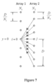
- Figure 7 illustrates multi-static array configuration effective sampling analysis, in accordance with one embodiment of the present invention.
- the left array, Array 1 has N 1 elements over unit cell length D for a spacing of D/N 1 .
- the right array, Array 2 has N 2 elements over unit cell length D for a spacing of D/N 2 .
- both arrays are assumed to be infinite above and below the portion under analysis, so that any array elements needed for effective sampling are available.
- that the transmit and receive separation not be too large, only separations of ⁇ D are used.
- the offset (iD / N 1 ) should uniformly shift through the effective sampling increment of the primary samples.
- the array is assumed to be infinite, or at least extend one additional unit cell length beyond the region under analysis, therefore only the portion of the offset that is the remainder after division by the primary sampling interval ( D / N 2 ) is important.
- Another consideration is that redundancy is undesirable, so effective samples with the shortest baseline separation are usually preferred.
- D 2 N 2 D 2 N 2 mod iN 2 N 1 1 + j
- the Array I index will vary over the integers i ⁇ [-2,-1,0,1,2].
- N 1 + 1 the figure of merit
- the figure of merit is slightly larger than N 1 . So, for the example above the number of samples per antenna will exceed 8. This allows a radical decrease in the number of antennas and switches required to build a dense, uniformly sampled linear array.
- Finite arrays can be specified by designating the length of the array L, number of unit cells N c , N 1 and N 2 .
- N 1 : N 2 : N c For convenience a specific array design will be designated by N 1 : N 2 : N c .
- An example 2:3:3 array is shown in Figure 8 .
- All unit cells in the array will have complete and uniform sampling except for the first and last cells, which, depending on the specific design have approximately half of the cell uniformly sampled (the half towards the center of the array).
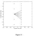
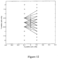
- Embodiments of this algorithm and of the sampling characteristics of the sparse multi-static array are shown in Figures 8-13 .
- a single unit cell of a 3:4 array is shown in Figure 8 and three unit cells are shown in Figure 9 .
- These figures illustrate the spacing and the periodicity of the arrays.
- the simplest type of array is a 1:1 array. This type of array violates the conditions stated above that N 2 > N 1 and that the numbers not share any common factors, so it will be considered a special limiting case.
- the unique samples for a single unit cell are shown in Figure 10 .
- This array is essentially equivalent to the separated transmit and receive array shown in Figure 2 , except for the shift in alignment of the two columns. This shift does not change the sampling density, but does make the two antenna pair baselines equal.
- FIG. 11 A more complex 1:3 array is shown in Figure 11 with the sampling for a single unit cell shown.
- Figure 12 shows a 2:3 array
- Figure 13 shows a 3:4 array. Note that in both these figures the sampling shown is uniform within a single unit cell (-0.5 ⁇ y ⁇ 0.5). The sampling outside of this region will be uniform as additional antenna pairings that were not shown are included. In all cases shown, the sampling is uniform within the unit cell and the number of samples is 2 N 1 N 2 .
- the array calibration techniques are more approximate because they must assume a direction of wave travel in order to estimate the path error.
- an on-axis propagation direction is assumed, which will work well for most cases, but may produce poor results in extreme near-field imaging conditions, or for arrays with very large baseline separations (i.e. large N 1 or N 2 ).
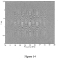
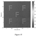
- the imaging performance of the sparse multi-static array technique can be demonstrated using phase history data that is synthesized. This synthesized data can then be reconstructed using at least two techniques.
- the range-domain multi-static generalized synthetic aperture focusing technique (RD-GSAFT) is applied.
- This technique uses the precisely known locations of each transmit and receive antenna in a phase-conjugate matched filtering method and is expected to perform the image reconstruction with the least imaging artifacts and highest dynamic range.
- This technique performs a coherent summation of the measured phase-history response multiplied by the expected response due to a hypothetical point scatter located at each image pixel or voxel. If an actual scatterer exists, then terms in this summation tend to add coherently producing a substantial response, whereas if there is no scatterer the terms tend to add incoherently and produce a minimal response.
Landscapes
- Engineering & Computer Science (AREA)
- Remote Sensing (AREA)
- Radar, Positioning & Navigation (AREA)
- Physics & Mathematics (AREA)
- Computer Networks & Wireless Communication (AREA)
- General Physics & Mathematics (AREA)
- Electromagnetism (AREA)
- Variable-Direction Aerials And Aerial Arrays (AREA)
- Radar Systems Or Details Thereof (AREA)
Claims (11)
- Multistatische Linear-Array-Vorrichtung für die synthetische Bildgebung eines Objekts, die Folgendes umfasst:a. ein lineares Array der ersten Spalte, das sich über mindestens zwei Einheitszellenlängen erstreckt, wobei jede Einheitszellenlänge eine erste Anzahl von Senderelementen enthält, die um einen ersten Abstand voneinander beabstandet sind; undb. ein lineares Array der zweiten Spalte, das sich über mindestens zwei Einheitszellenlängen erstreckt, wobei jede Einheitszellenlänge eine zweite Anzahl von Empfängerelementen enthält, die um einen zweiten Abstand voneinander beabstandet sind, so dass effektive Abtastungen an einem Ort ungefähr auf halber Strecke zwischen Phasenzentren der individuellen Sender- und Empfänger-Paare der Sender- und Empfänger-Elemente erhalten werden, wobei die erste Anzahl ein nicht ganzzahliges Vielfaches der zweiten Anzahl ist und die zweite Anzahl ein nicht ganzzahliges Vielfaches der ersten Anzahl ist, und eine Anzahl von effektiven Abtastungen, die innerhalb einer Einheitszellenlänge erhalten werden, mindestens gleich der doppelten Anzahl der mehreren Sender- und Empfänger-Elemente in einer Einheitszelle ist, wobei die zweite Anzahl größer ist als die erste Anzahl und die erste Anzahl und die zweite Anzahl keine gemeinsamen Faktoren aufweisen, wobei jedes Senderelement in der ersten Spalte um einen Abstand beabstandet ist, der ungefähr gleich der Einheitszellenlänge geteilt durch die erste Anzahl ist, und jedes Empfängerelement in der zweiten Spalte um einen Abstand beabstandet ist, der ungefähr gleich der Einheitszellenlänge geteilt durch die zweite Anzahl ist.
- Vorrichtung nach Anspruch 1, wobei gleichmäßiges Abtasten über eine Einheitszellenlänge erzielt wird.
- Vorrichtung nach Anspruch 1, wobei die durch die Senderelemente und die Empfängerelemente erhaltenen Abtastungen um einen Bruchteil einer Wellenlänge eng beabstandet sind.
- Vorrichtung nach Anspruch 1, wobei die Elemente in dem Bereich von 200 MHz-1 THz arbeiten.
- Vorrichtung nach Anspruch 1, wobei die Elemente eine Zeile einer planaren oder zylindrischen Apertur elektronisch abtasten.
- Vorrichtung nach Anspruch 5, wobei die Apertur ungefähr 0,1 bis ungefähr 20 Meter hoch ist.
- Vorrichtung nach einem der Ansprüche 1 oder 2, wobei jedes Senderelement und jedes Empfängerelement mehrfach verwendet wird, um mehrere Abtastungen pro Einheitszelle zu erhalten.
- Vorrichtung nach Anspruch 1, wobei die erste Anzahl von Senderelementen in einer ersten räumlichen Dimension und einer zweiten räumlichen Dimension gleichmäßig beabstandet sind und die zweite Anzahl von Empfängerelementen in der ersten räumlichen Dimension und der zweiten räumlichen Dimension gleichmäßig beabstandet sind, so dass die gleichmäßigen Abstände der Empfängerelemente sich von den gleichmäßigen Abständen der Senderelemente unterscheiden, wobei die erste räumliche Dimension der X-Richtung eines zweidimensionalen Arrays und die zweite räumliche Dimension der Y-Richtung eines zweidimensionalen Arrays entspricht, wobei die Senderelemente und die Empfängerelemente sowohl in der X-Dimension als auch in der Y-Dimension wiederholt werden, wobei die Perioden durch die Anzahl der Einheitszellen in jeder Dimension eingestellt werden.
- Vorrichtung nach Anspruch 1, wobei mindestens ein Senderelement und ein Empfängerelement an den Scheitelpunkten jeder Einheitszelle gemeinsam angeordnet sind.
- Verfahren zur synthetischen Bildgebung eines Objekts unter Verwendung einer multistatischen Linear-Array-Vorrichtung, das Folgendes umfasst:a. Bereitstellen eines linearen Arrays der ersten Spalte, das sich über mindestens zwei Einheitszellenlängen erstreckt, wobei jede Einheitszellenlänge eine erste Anzahl von Senderelementen enthält, die in einer ersten Spalte um einen ersten Abstand voneinander beabstandet sind;b. Bereitstellen eines linearen Arrays der zweiten Spalte, das sich über mindestens zwei Einheitszellenlängen erstreckt, wobei jede Einheitszellenlänge eine zweite Anzahl von Empfängerelementen enthält, die in einer zweiten Spalte um einen zweiten Abstand voneinander beabstandet sind;c. Erhalten einer einzelnen Spalte von effektiven Abtastungen aus individuellen Sender- und Empfänger-Paaren der mehreren Senderelemente und Empfängerelemente;d. Erzielen eines gleichmäßigen Abtastens über eine Einheitszellenlänge, wobei die erste Anzahl ein nicht ganzzahliges Vielfaches der zweiten Anzahl ist und die zweite Anzahl ein nicht ganzzahliges Vielfaches der ersten Anzahl ist, unddie Anzahl der effektiven Abtastungen, die innerhalb einer Einheitszellenlänge erhalten werden, mindestens gleich der doppelten Anzahl der mehreren Sender- und Empfänger-Elemente in einer Einheitszelle ist, wobei die zweite Anzahl größer ist als die erste Anzahl und die erste Anzahl und die zweite Anzahl keine gemeinsamen Faktoren aufweisen, wobei jedes Senderelement in der ersten Spalte um einen Abstand beabstandet ist, der ungefähr gleich der Einheitszellenlänge geteilt durch die erste Anzahl ist, und jedes Empfängerelement in der zweiten Spalte um einen Abstand beabstandet ist, der ungefähr gleich der Einheitszellenlänge geteilt durch die zweite Anzahl ist.
- Verfahren nach Anspruch 10, das ferner das mehrmalige Verwenden jedes der Senderelemente und jedes der Empfängerelemente umfasst, um mehrere Abtastungen pro Einheitszelle zu erhalten.
Applications Claiming Priority (2)
| Application Number | Priority Date | Filing Date | Title |
|---|---|---|---|
| US13/629,849 US8937570B2 (en) | 2012-09-28 | 2012-09-28 | Apparatus for synthetic imaging of an object |
| PCT/US2013/051970 WO2014058512A2 (en) | 2012-09-28 | 2013-07-25 | Apparatus for synthetic imaging of an object |
Publications (2)
| Publication Number | Publication Date |
|---|---|
| EP2898569A2 EP2898569A2 (de) | 2015-07-29 |
| EP2898569B1 true EP2898569B1 (de) | 2024-12-25 |
Family
ID=50070656
Family Applications (1)
| Application Number | Title | Priority Date | Filing Date |
|---|---|---|---|
| EP13828894.9A Active EP2898569B1 (de) | 2012-09-28 | 2013-07-25 | Vorrichtung für synthetische bildgebung eines objekts |
Country Status (6)
| Country | Link |
|---|---|
| US (1) | US8937570B2 (de) |
| EP (1) | EP2898569B1 (de) |
| AU (1) | AU2013330383B2 (de) |
| CA (1) | CA2883082C (de) |
| ES (1) | ES3013899T3 (de) |
| WO (1) | WO2014058512A2 (de) |
Families Citing this family (35)
| Publication number | Priority date | Publication date | Assignee | Title |
|---|---|---|---|---|
| US8937570B2 (en) * | 2012-09-28 | 2015-01-20 | Battelle Memorial Institute | Apparatus for synthetic imaging of an object |
| US9316734B2 (en) * | 2012-10-19 | 2016-04-19 | The Curators Of The University Of Missouri | Free-hand scanning and imaging |
| WO2014074631A1 (en) * | 2012-11-07 | 2014-05-15 | Neva Ridge Technologies | Sar point cloud generation system |
| US9715012B2 (en) | 2013-04-25 | 2017-07-25 | Battelle Memorial Institute | Footwear scanning systems and methods |
| KR20140144826A (ko) * | 2013-06-12 | 2014-12-22 | 주식회사 만도 | 레이더 장치 및 안테나 장치 |
| WO2015155764A1 (en) * | 2014-04-07 | 2015-10-15 | Gideon Levita | Electromagnetic search and identification, in near field arenas |
| JP6553335B2 (ja) * | 2014-06-30 | 2019-07-31 | 日本信号株式会社 | 送受信装置、およびレーダ計測システム |
| US11340345B2 (en) * | 2015-07-17 | 2022-05-24 | Origin Wireless, Inc. | Method, apparatus, and system for wireless object tracking |
| CN104215953B (zh) * | 2014-08-28 | 2017-02-15 | 中国科学院电子学研究所 | 基于柱面扫描三维近场成像的反向散射截面测量方法 |
| CN104269612B (zh) * | 2014-10-15 | 2016-07-13 | 内蒙古工业大学 | 近距离平面阵列多输入多输出成像天线布局方法 |
| CN105068069B (zh) * | 2015-09-09 | 2018-12-21 | 同方威视技术股份有限公司 | 毫米波三维全息扫描成像设备及成像方法 |
| CN114185042B (zh) * | 2015-09-17 | 2025-08-12 | 松下汽车电子系统株式会社 | 雷达装置 |
| CN109328309A (zh) * | 2015-12-17 | 2019-02-12 | 麻省理工学院 | 用于近场微波成像的方法和系统 |
| US10527715B2 (en) * | 2016-06-20 | 2020-01-07 | Rohde & Schwarz Gmbh & Co. Kg | Radar target stimulation device and method |
| US9869583B1 (en) | 2016-10-27 | 2018-01-16 | Northrop Grumman Systems Corporation | Image scanning on a sparsely populated focal plane array to achieve nyquist sampling |
| US11555916B2 (en) * | 2016-12-08 | 2023-01-17 | University Of Washington | Millimeter wave and/or microwave imaging systems and methods including examples of partitioned inverse and enhanced resolution modes and imaging devices |
| JP2020521941A (ja) * | 2016-12-29 | 2020-07-27 | ラドシー テクノロジーズ リミテッド | アンテナ・アレイ |
| CN108445457B (zh) * | 2018-02-12 | 2020-08-04 | 中国人民解放军61540部队 | 星载分布式干涉合成孔径雷达三维基线定标的方法 |
| US10371797B1 (en) * | 2018-05-23 | 2019-08-06 | Zendar Inc. | Systems and methods for enhancing target detection |
| EP3647826B1 (de) * | 2018-08-17 | 2025-02-19 | Tsinghua University | Gruppenantennenanordnung mit mehrfacher sendung und mehrfachem empfang für aktive millimeterwellen-sicherheitsinspektionsbildgebung sowie verfahren und vorrichtung zur sicherheitsinspektion des menschlichen körpers |
| CN109782366A (zh) * | 2018-12-29 | 2019-05-21 | 清华大学 | 用于主动式毫米波安检成像的多发多收天线阵列布置、人体安检设备和方法 |
| CN109799546A (zh) * | 2018-12-29 | 2019-05-24 | 清华大学 | 用于主动式毫米波安检成像的多发多收天线阵列布置、人体安检设备和人体安检方法 |
| CN109799545A (zh) * | 2018-12-29 | 2019-05-24 | 清华大学 | 用于主动式毫米波安检成像的多发多收天线阵列布置、人体安检设备和人体安检方法 |
| CN109444968B (zh) * | 2018-12-29 | 2024-06-11 | 清华大学 | 安检设备及其控制方法 |
| CN109799537A (zh) * | 2018-12-29 | 2019-05-24 | 清华大学 | 安检设备及其控制方法 |
| CN109471197A (zh) * | 2018-12-29 | 2019-03-15 | 同方威视技术股份有限公司 | 安检设备及其控制方法 |
| CN109799538B (zh) * | 2018-12-29 | 2024-10-18 | 清华大学 | 安检设备及其控制方法 |
| CN109444969A (zh) * | 2018-12-29 | 2019-03-08 | 清华大学 | 安检设备及其控制方法 |
| US11715228B2 (en) | 2019-04-04 | 2023-08-01 | Battelle Memorial Institute | Imaging systems and related methods including radar imaging with moving arrays or moving targets |
| CN113126084A (zh) * | 2019-12-31 | 2021-07-16 | 同方威视技术股份有限公司 | 用于主动式毫米波安检成像的多发多收天线阵列布置、人体安检设备和方法 |
| US11520069B2 (en) | 2020-04-20 | 2022-12-06 | Battelle Memorial Institute | Footwear scanning systems and methods |
| JP7467307B2 (ja) * | 2020-10-01 | 2024-04-15 | 株式会社東芝 | システム及び方法 |
| CN112799064B (zh) * | 2020-12-30 | 2023-05-26 | 内蒙古工业大学 | 柱面孔径非线性渐进式相位迭代成像的方法及装置 |
| CN112768955B (zh) * | 2021-01-04 | 2022-12-13 | 上海航天测控通信研究所 | 一种抗混叠旋转错位阵列天线 |
| CA3187487A1 (en) | 2021-04-08 | 2022-10-13 | Richard Trevor Clark | Surface determination systems, threat detection systems and medical treatment systems |
Citations (2)
| Publication number | Priority date | Publication date | Assignee | Title |
|---|---|---|---|---|
| US20110140949A1 (en) * | 2009-12-16 | 2011-06-16 | Electronics And Telecommunications Research Institute | Mimo radar apparatus and wireless communication method using the same |
| US20120105268A1 (en) * | 2009-02-20 | 2012-05-03 | Nederlandse Organisatie Voor Toegepast-Natuurwetenschappelijk Onderzoek Tno | Method of Detecting a Scatterer in a Structure, a Radar System and a Computer Program Product |
Family Cites Families (25)
| Publication number | Priority date | Publication date | Assignee | Title |
|---|---|---|---|---|
| US5546357A (en) * | 1993-06-30 | 1996-08-13 | The United States Of America As Represented By The Secretary Of The Navy | Monostatic projector synthetic aperture sonar |
| US5537367A (en) * | 1994-10-20 | 1996-07-16 | Lockwood; Geoffrey R. | Sparse array structures |
| MXPA02004221A (es) * | 1999-10-26 | 2003-08-20 | Fractus Sa | Agrupaciones multibanda de antenas entrelazadas. |
| US6700526B2 (en) * | 2000-09-08 | 2004-03-02 | Witten Technologies Inc. | Method and apparatus for identifying buried objects using ground penetrating radar |
| US7183995B2 (en) * | 2001-08-16 | 2007-02-27 | Raytheon Company | Antenna configurations for reduced radar complexity |
| KR20040025113A (ko) * | 2002-09-18 | 2004-03-24 | 한국전자통신연구원 | 부엽레벨 억압을 위한 마이크로스트립 패치 배열 안테나 |
| JP3988653B2 (ja) * | 2003-02-10 | 2007-10-10 | 株式会社デンソー | アンテナの配列方法、及びレーダ装置 |
| DE10316637A1 (de) | 2003-04-11 | 2004-10-28 | Robert Bosch Gmbh | Radar-Antennenanordnung |
| JP4087280B2 (ja) * | 2003-04-15 | 2008-05-21 | 株式会社リコー | 画像処理装置、画像処理方法および画像処理システム |
| US6970133B2 (en) * | 2003-06-04 | 2005-11-29 | Lockheed Martin Corporation | Antenna system and method of using same |
| JP2006003303A (ja) * | 2004-06-21 | 2006-01-05 | Fujitsu Ten Ltd | レーダ装置 |
| WO2007011295A1 (en) * | 2005-07-22 | 2007-01-25 | Powerwave Technologies Sweden Ab | Antenna arrangement with interleaved antenna elements |
| US7548185B2 (en) * | 2005-09-30 | 2009-06-16 | Battelle Memorial Institute | Interlaced linear array sampling technique for electromagnetic wave imaging |
| WO2007083479A1 (ja) * | 2006-01-23 | 2007-07-26 | Murata Manufacturing Co., Ltd. | レーダ装置 |
| WO2008057286A2 (en) * | 2006-10-27 | 2008-05-15 | Clariant Technologies Corp. | Method and apparatus for microwave and millimeter-wave imaging |
| JP4905457B2 (ja) * | 2006-11-01 | 2012-03-28 | 株式会社村田製作所 | レーダの物標検知方法、およびこの物標検知方法を用いたレーダ装置 |
| JP4545174B2 (ja) * | 2007-06-11 | 2010-09-15 | 三菱電機株式会社 | レーダ装置 |
| EP2423704B1 (de) * | 2009-04-23 | 2020-07-15 | Mitsubishi Electric Corporation | Radargerät und antennenvorrichtung |
| EP2256860B1 (de) * | 2009-05-26 | 2018-12-19 | Alcatel Lucent | Gruppenantenne |
| US8558740B2 (en) * | 2009-06-29 | 2013-10-15 | Viasat, Inc. | Hybrid single aperture inclined antenna |
| JP2011064584A (ja) * | 2009-09-17 | 2011-03-31 | Denso Corp | アレーアンテナ装置及びレーダ装置 |
| EP2315312A1 (de) * | 2009-10-22 | 2011-04-27 | Toyota Motor Europe NV | Antenne mit schwach besetzter Gruppe von Elementen |
| US8378878B2 (en) * | 2010-08-05 | 2013-02-19 | ARETé ASSOCIATES | Creating and processing universal radar waveforms |
| NO335737B1 (no) * | 2011-02-09 | 2015-02-02 | Kongsberg Maritime As | Antennegruppesystem med høy oppløsningsevne og høy bildekvalitet |
| US8937570B2 (en) * | 2012-09-28 | 2015-01-20 | Battelle Memorial Institute | Apparatus for synthetic imaging of an object |
-
2012
- 2012-09-28 US US13/629,849 patent/US8937570B2/en active Active
-
2013
- 2013-07-25 CA CA2883082A patent/CA2883082C/en active Active
- 2013-07-25 WO PCT/US2013/051970 patent/WO2014058512A2/en not_active Ceased
- 2013-07-25 EP EP13828894.9A patent/EP2898569B1/de active Active
- 2013-07-25 AU AU2013330383A patent/AU2013330383B2/en active Active
- 2013-07-25 ES ES13828894T patent/ES3013899T3/es active Active
Patent Citations (2)
| Publication number | Priority date | Publication date | Assignee | Title |
|---|---|---|---|---|
| US20120105268A1 (en) * | 2009-02-20 | 2012-05-03 | Nederlandse Organisatie Voor Toegepast-Natuurwetenschappelijk Onderzoek Tno | Method of Detecting a Scatterer in a Structure, a Radar System and a Computer Program Product |
| US20110140949A1 (en) * | 2009-12-16 | 2011-06-16 | Electronics And Telecommunications Research Institute | Mimo radar apparatus and wireless communication method using the same |
Non-Patent Citations (1)
| Title |
|---|
| PALGHAT P VAIDYANATHAN ET AL: "Sparse Sensing With Co-Prime Samplers and Arrays", IEEE TRANSACTIONS ON SIGNAL PROCESSING, IEEE, USA, vol. 59, no. 2, 1 February 2011 (2011-02-01), pages 573 - 586, XP011343886, ISSN: 1053-587X, DOI: 10.1109/TSP.2010.2089682 * |
Also Published As
| Publication number | Publication date |
|---|---|
| AU2013330383B2 (en) | 2017-08-31 |
| WO2014058512A2 (en) | 2014-04-17 |
| AU2013330383A1 (en) | 2015-03-19 |
| CA2883082A1 (en) | 2014-04-17 |
| ES3013899T3 (en) | 2025-04-15 |
| EP2898569A2 (de) | 2015-07-29 |
| CA2883082C (en) | 2021-03-09 |
| US20140091965A1 (en) | 2014-04-03 |
| US8937570B2 (en) | 2015-01-20 |
| WO2014058512A3 (en) | 2014-06-05 |
Similar Documents
| Publication | Publication Date | Title |
|---|---|---|
| EP2898569B1 (de) | Vorrichtung für synthetische bildgebung eines objekts | |
| CN103278817B (zh) | 用于通过测量空间频率分量进行雷达成像的装置和方法 | |
| CN105589058B (zh) | 一种天线装置及三维雷达系统 | |
| US20160077195A1 (en) | Radar imaging via spatial spectrum measurement and MIMO waveforms | |
| CN108761452A (zh) | 距离补偿的多输入多输出阵列毫米波三维成像装置及方法 | |
| CN106597442B (zh) | 一种方位多通道脉内聚束sar成像方法 | |
| DE102016224900A1 (de) | MIMO-Radarsensor für Kraftfahrzeuge | |
| CN110412568A (zh) | 基于扩展方位角相位编码的距离模糊杂波抑制方法 | |
| EP3845931B1 (de) | Mimo-antennen-array-anordnung für eine aktive millimeterwellen-sicherheitsinspektionsabbildung, gerät und verfahren zur sicherheitsinspektion des menschlichen körpers | |
| Sheen | Sparse multi-static arrays for near-field millimeter-wave imaging | |
| WO2017155573A1 (en) | Correlated fanbeam extruder | |
| Re et al. | FMCW radar with enhanced resolution and processing time by beam switching | |
| CN110412570A (zh) | 基于空间脉冲相位编码的hrws-sar成像方法 | |
| EP0181935B1 (de) | Fächerstrahlumkehrung benutzendes mikrowellenradiometer | |
| Rommel et al. | An orthogonal waveform scheme for imaging MIMO-Radar applications | |
| EP3814798B1 (de) | Bodenbasierendes radar mit synthetischer apertur (gbsar) mit mehreren sende- und empfangsantennen (mimo) und verwendung der als kompressive erfassung bezeichneten verarbeitungstechnik | |
| CN115932852B (zh) | 基于非均匀子脉冲编码的sar-gmti距离模糊抑制方法 | |
| KR20260044922A (ko) | Sar 센서를 보정하는 방법 | |
| Sheen | Apparatus for synthetic imaging of an object | |
| Hysell et al. | Aperture synthesis imaging of ionospheric irregularities using time diversity MIMO radar | |
| El Arja et al. | Joint TOA/DOA measurements for UWB indoor propagation channel using MUSIC algorithm | |
| Leino et al. | Millimeter-wave frequency-diverse imaging with phased array intended for communications | |
| Le Marshall et al. | MIMO radar array for termite detection and imaging | |
| CN208569033U (zh) | 距离补偿的多输入多输出阵列毫米波三维成像装置 | |
| Rommel et al. | Development of a MIMO Radar System demonstrator-Calibration and demonstration of first results |
Legal Events
| Date | Code | Title | Description |
|---|---|---|---|
| PUAI | Public reference made under article 153(3) epc to a published international application that has entered the european phase |
Free format text: ORIGINAL CODE: 0009012 |
|
| 17P | Request for examination filed |
Effective date: 20150425 |
|
| AK | Designated contracting states |
Kind code of ref document: A2 Designated state(s): AL AT BE BG CH CY CZ DE DK EE ES FI FR GB GR HR HU IE IS IT LI LT LU LV MC MK MT NL NO PL PT RO RS SE SI SK SM TR |
|
| AX | Request for extension of the european patent |
Extension state: BA ME |
|
| DAX | Request for extension of the european patent (deleted) | ||
| STAA | Information on the status of an ep patent application or granted ep patent |
Free format text: STATUS: EXAMINATION IS IN PROGRESS |
|
| 17Q | First examination report despatched |
Effective date: 20171030 |
|
| REG | Reference to a national code |
Ref country code: DE Ref legal event code: R079 Free format text: PREVIOUS MAIN CLASS: H01Q0021080000 Ipc: G01S0013420000 Ref country code: DE Ref legal event code: R079 Ref document number: 602013086401 Country of ref document: DE Free format text: PREVIOUS MAIN CLASS: H01Q0021080000 Ipc: G01S0013420000 |
|
| GRAP | Despatch of communication of intention to grant a patent |
Free format text: ORIGINAL CODE: EPIDOSNIGR1 |
|
| STAA | Information on the status of an ep patent application or granted ep patent |
Free format text: STATUS: GRANT OF PATENT IS INTENDED |
|
| RIC1 | Information provided on ipc code assigned before grant |
Ipc: G01S 13/42 20060101AFI20240129BHEP |
|
| INTG | Intention to grant announced |
Effective date: 20240222 |
|
| GRAJ | Information related to disapproval of communication of intention to grant by the applicant or resumption of examination proceedings by the epo deleted |
Free format text: ORIGINAL CODE: EPIDOSDIGR1 |
|
| STAA | Information on the status of an ep patent application or granted ep patent |
Free format text: STATUS: EXAMINATION IS IN PROGRESS |
|
| GRAP | Despatch of communication of intention to grant a patent |
Free format text: ORIGINAL CODE: EPIDOSNIGR1 |
|
| STAA | Information on the status of an ep patent application or granted ep patent |
Free format text: STATUS: GRANT OF PATENT IS INTENDED |
|
| INTC | Intention to grant announced (deleted) | ||
| INTG | Intention to grant announced |
Effective date: 20240723 |
|
| RAP3 | Party data changed (applicant data changed or rights of an application transferred) |
Owner name: BATTELLE MEMORIAL INSTITUTE |
|
| GRAS | Grant fee paid |
Free format text: ORIGINAL CODE: EPIDOSNIGR3 |
|
| GRAA | (expected) grant |
Free format text: ORIGINAL CODE: 0009210 |
|
| STAA | Information on the status of an ep patent application or granted ep patent |
Free format text: STATUS: THE PATENT HAS BEEN GRANTED |
|
| AK | Designated contracting states |
Kind code of ref document: B1 Designated state(s): AL AT BE BG CH CY CZ DE DK EE ES FI FR GB GR HR HU IE IS IT LI LT LU LV MC MK MT NL NO PL PT RO RS SE SI SK SM TR |
|
| REG | Reference to a national code |
Ref country code: GB Ref legal event code: FG4D |
|
| REG | Reference to a national code |
Ref country code: CH Ref legal event code: EP |
|
| REG | Reference to a national code |
Ref country code: DE Ref legal event code: R096 Ref document number: 602013086401 Country of ref document: DE |
|
| REG | Reference to a national code |
Ref country code: IE Ref legal event code: FG4D |
|
| REG | Reference to a national code |
Ref country code: NL Ref legal event code: FP |
|
| REG | Reference to a national code |
Ref country code: LT Ref legal event code: MG9D |
|
| PG25 | Lapsed in a contracting state [announced via postgrant information from national office to epo] |
Ref country code: HR Free format text: LAPSE BECAUSE OF FAILURE TO SUBMIT A TRANSLATION OF THE DESCRIPTION OR TO PAY THE FEE WITHIN THE PRESCRIBED TIME-LIMIT Effective date: 20241225 |
|
| PG25 | Lapsed in a contracting state [announced via postgrant information from national office to epo] |
Ref country code: FI Free format text: LAPSE BECAUSE OF FAILURE TO SUBMIT A TRANSLATION OF THE DESCRIPTION OR TO PAY THE FEE WITHIN THE PRESCRIBED TIME-LIMIT Effective date: 20241225 |
|
| REG | Reference to a national code |
Ref country code: ES Ref legal event code: FG2A Ref document number: 3013899 Country of ref document: ES Kind code of ref document: T3 Effective date: 20250415 |
|
| PG25 | Lapsed in a contracting state [announced via postgrant information from national office to epo] |
Ref country code: BG Free format text: LAPSE BECAUSE OF FAILURE TO SUBMIT A TRANSLATION OF THE DESCRIPTION OR TO PAY THE FEE WITHIN THE PRESCRIBED TIME-LIMIT Effective date: 20241225 |
|
| PG25 | Lapsed in a contracting state [announced via postgrant information from national office to epo] |
Ref country code: NO Free format text: LAPSE BECAUSE OF FAILURE TO SUBMIT A TRANSLATION OF THE DESCRIPTION OR TO PAY THE FEE WITHIN THE PRESCRIBED TIME-LIMIT Effective date: 20250325 |
|
| PG25 | Lapsed in a contracting state [announced via postgrant information from national office to epo] |
Ref country code: GR Free format text: LAPSE BECAUSE OF FAILURE TO SUBMIT A TRANSLATION OF THE DESCRIPTION OR TO PAY THE FEE WITHIN THE PRESCRIBED TIME-LIMIT Effective date: 20250326 Ref country code: LV Free format text: LAPSE BECAUSE OF FAILURE TO SUBMIT A TRANSLATION OF THE DESCRIPTION OR TO PAY THE FEE WITHIN THE PRESCRIBED TIME-LIMIT Effective date: 20241225 |
|
| PG25 | Lapsed in a contracting state [announced via postgrant information from national office to epo] |
Ref country code: RS Free format text: LAPSE BECAUSE OF FAILURE TO SUBMIT A TRANSLATION OF THE DESCRIPTION OR TO PAY THE FEE WITHIN THE PRESCRIBED TIME-LIMIT Effective date: 20250325 |
|
| REG | Reference to a national code |
Ref country code: AT Ref legal event code: MK05 Ref document number: 1754622 Country of ref document: AT Kind code of ref document: T Effective date: 20241225 |
|
| PG25 | Lapsed in a contracting state [announced via postgrant information from national office to epo] |
Ref country code: SM Free format text: LAPSE BECAUSE OF FAILURE TO SUBMIT A TRANSLATION OF THE DESCRIPTION OR TO PAY THE FEE WITHIN THE PRESCRIBED TIME-LIMIT Effective date: 20241225 |
|
| PG25 | Lapsed in a contracting state [announced via postgrant information from national office to epo] |
Ref country code: PL Free format text: LAPSE BECAUSE OF FAILURE TO SUBMIT A TRANSLATION OF THE DESCRIPTION OR TO PAY THE FEE WITHIN THE PRESCRIBED TIME-LIMIT Effective date: 20241225 |
|
| PG25 | Lapsed in a contracting state [announced via postgrant information from national office to epo] |
Ref country code: IS Free format text: LAPSE BECAUSE OF FAILURE TO SUBMIT A TRANSLATION OF THE DESCRIPTION OR TO PAY THE FEE WITHIN THE PRESCRIBED TIME-LIMIT Effective date: 20250425 |
|
| PGFP | Annual fee paid to national office [announced via postgrant information from national office to epo] |
Ref country code: NL Payment date: 20250620 Year of fee payment: 13 |
|
| PG25 | Lapsed in a contracting state [announced via postgrant information from national office to epo] |
Ref country code: PT Free format text: LAPSE BECAUSE OF FAILURE TO SUBMIT A TRANSLATION OF THE DESCRIPTION OR TO PAY THE FEE WITHIN THE PRESCRIBED TIME-LIMIT Effective date: 20250428 |
|
| PG25 | Lapsed in a contracting state [announced via postgrant information from national office to epo] |
Ref country code: EE Free format text: LAPSE BECAUSE OF FAILURE TO SUBMIT A TRANSLATION OF THE DESCRIPTION OR TO PAY THE FEE WITHIN THE PRESCRIBED TIME-LIMIT Effective date: 20241225 |
|
| PG25 | Lapsed in a contracting state [announced via postgrant information from national office to epo] |
Ref country code: RO Free format text: LAPSE BECAUSE OF FAILURE TO SUBMIT A TRANSLATION OF THE DESCRIPTION OR TO PAY THE FEE WITHIN THE PRESCRIBED TIME-LIMIT Effective date: 20241225 Ref country code: AT Free format text: LAPSE BECAUSE OF FAILURE TO SUBMIT A TRANSLATION OF THE DESCRIPTION OR TO PAY THE FEE WITHIN THE PRESCRIBED TIME-LIMIT Effective date: 20241225 |
|
| PG25 | Lapsed in a contracting state [announced via postgrant information from national office to epo] |
Ref country code: SK Free format text: LAPSE BECAUSE OF FAILURE TO SUBMIT A TRANSLATION OF THE DESCRIPTION OR TO PAY THE FEE WITHIN THE PRESCRIBED TIME-LIMIT Effective date: 20241225 |
|
| PG25 | Lapsed in a contracting state [announced via postgrant information from national office to epo] |
Ref country code: CZ Free format text: LAPSE BECAUSE OF FAILURE TO SUBMIT A TRANSLATION OF THE DESCRIPTION OR TO PAY THE FEE WITHIN THE PRESCRIBED TIME-LIMIT Effective date: 20241225 |
|
| PG25 | Lapsed in a contracting state [announced via postgrant information from national office to epo] |
Ref country code: SE Free format text: LAPSE BECAUSE OF FAILURE TO SUBMIT A TRANSLATION OF THE DESCRIPTION OR TO PAY THE FEE WITHIN THE PRESCRIBED TIME-LIMIT Effective date: 20241225 |
|
| REG | Reference to a national code |
Ref country code: DE Ref legal event code: R097 Ref document number: 602013086401 Country of ref document: DE |
|
| PG25 | Lapsed in a contracting state [announced via postgrant information from national office to epo] |
Ref country code: DK Free format text: LAPSE BECAUSE OF FAILURE TO SUBMIT A TRANSLATION OF THE DESCRIPTION OR TO PAY THE FEE WITHIN THE PRESCRIBED TIME-LIMIT Effective date: 20241225 |
|
| PGFP | Annual fee paid to national office [announced via postgrant information from national office to epo] |
Ref country code: IT Payment date: 20250714 Year of fee payment: 13 |
|
| PLBE | No opposition filed within time limit |
Free format text: ORIGINAL CODE: 0009261 |
|
| STAA | Information on the status of an ep patent application or granted ep patent |
Free format text: STATUS: NO OPPOSITION FILED WITHIN TIME LIMIT |
|
| REG | Reference to a national code |
Ref country code: CH Ref legal event code: L10 Free format text: ST27 STATUS EVENT CODE: U-0-0-L10-L00 (AS PROVIDED BY THE NATIONAL OFFICE) Effective date: 20251105 |
|
| 26N | No opposition filed |
Effective date: 20250926 |
|
| REG | Reference to a national code |
Ref country code: CH Ref legal event code: H13 Free format text: ST27 STATUS EVENT CODE: U-0-0-H10-H13 (AS PROVIDED BY THE NATIONAL OFFICE) Effective date: 20260224 |
|
| PG25 | Lapsed in a contracting state [announced via postgrant information from national office to epo] |
Ref country code: LU Free format text: LAPSE BECAUSE OF NON-PAYMENT OF DUE FEES Effective date: 20250725 |
|
| REG | Reference to a national code |
Ref country code: BE Ref legal event code: MM Effective date: 20250731 |
|
| PGFP | Annual fee paid to national office [announced via postgrant information from national office to epo] |
Ref country code: GB Payment date: 20260102 Year of fee payment: 13 |
|
| PGFP | Annual fee paid to national office [announced via postgrant information from national office to epo] |
Ref country code: ES Payment date: 20260112 Year of fee payment: 13 |
|
| PGFP | Annual fee paid to national office [announced via postgrant information from national office to epo] |
Ref country code: DE Payment date: 20260116 Year of fee payment: 13 |
|
| PG25 | Lapsed in a contracting state [announced via postgrant information from national office to epo] |
Ref country code: BE Free format text: LAPSE BECAUSE OF NON-PAYMENT OF DUE FEES Effective date: 20250731 |
|
| PGFP | Annual fee paid to national office [announced via postgrant information from national office to epo] |
Ref country code: FR Payment date: 20260121 Year of fee payment: 13 |
|
| PG25 | Lapsed in a contracting state [announced via postgrant information from national office to epo] |
Ref country code: CH Free format text: LAPSE BECAUSE OF NON-PAYMENT OF DUE FEES Effective date: 20250731 |