EP2897259A2 - Rotierende elektrische Maschine - Google Patents
Rotierende elektrische Maschine Download PDFInfo
- Publication number
- EP2897259A2 EP2897259A2 EP15000110.5A EP15000110A EP2897259A2 EP 2897259 A2 EP2897259 A2 EP 2897259A2 EP 15000110 A EP15000110 A EP 15000110A EP 2897259 A2 EP2897259 A2 EP 2897259A2
- Authority
- EP
- European Patent Office
- Prior art keywords
- electric machine
- rotating electric
- liquid coolant
- flow passage
- cooling
- Prior art date
- Legal status (The legal status is an assumption and is not a legal conclusion. Google has not performed a legal analysis and makes no representation as to the accuracy of the status listed.)
- Granted
Links
- 239000002826 coolant Substances 0.000 claims abstract description 139
- 238000001816 cooling Methods 0.000 claims abstract description 122
- 239000007788 liquid Substances 0.000 claims abstract description 120
- 239000007789 gas Substances 0.000 claims 4
- 239000000112 cooling gas Substances 0.000 claims 1
- XEEYBQQBJWHFJM-UHFFFAOYSA-N Iron Chemical compound [Fe] XEEYBQQBJWHFJM-UHFFFAOYSA-N 0.000 description 10
- XLYOFNOQVPJJNP-UHFFFAOYSA-N water Substances O XLYOFNOQVPJJNP-UHFFFAOYSA-N 0.000 description 9
- 238000000034 method Methods 0.000 description 7
- 230000004907 flux Effects 0.000 description 6
- RYGMFSIKBFXOCR-UHFFFAOYSA-N Copper Chemical compound [Cu] RYGMFSIKBFXOCR-UHFFFAOYSA-N 0.000 description 5
- 229910052802 copper Inorganic materials 0.000 description 5
- 239000010949 copper Substances 0.000 description 5
- 229910052742 iron Inorganic materials 0.000 description 5
- 230000020169 heat generation Effects 0.000 description 3
- 238000005728 strengthening Methods 0.000 description 3
- 239000000498 cooling water Substances 0.000 description 2
- 230000008859 change Effects 0.000 description 1
- 238000012217 deletion Methods 0.000 description 1
- 230000037430 deletion Effects 0.000 description 1
- 230000000694 effects Effects 0.000 description 1
- 230000005484 gravity Effects 0.000 description 1
- 230000006872 improvement Effects 0.000 description 1
- 230000006698 induction Effects 0.000 description 1
- 238000012986 modification Methods 0.000 description 1
- 230000004048 modification Effects 0.000 description 1
- 230000008569 process Effects 0.000 description 1
- 230000002123 temporal effect Effects 0.000 description 1
Images


Classifications
-
- H—ELECTRICITY
- H02—GENERATION; CONVERSION OR DISTRIBUTION OF ELECTRIC POWER
- H02K—DYNAMO-ELECTRIC MACHINES
- H02K9/00—Arrangements for cooling or ventilating
- H02K9/19—Arrangements for cooling or ventilating for machines with closed casing and closed-circuit cooling using a liquid cooling medium, e.g. oil
- H02K9/197—Arrangements for cooling or ventilating for machines with closed casing and closed-circuit cooling using a liquid cooling medium, e.g. oil in which the rotor or stator space is fluid-tight, e.g. to provide for different cooling media for rotor and stator
-
- H—ELECTRICITY
- H02—GENERATION; CONVERSION OR DISTRIBUTION OF ELECTRIC POWER
- H02K—DYNAMO-ELECTRIC MACHINES
- H02K5/00—Casings; Enclosures; Supports
- H02K5/04—Casings or enclosures characterised by the shape, form or construction thereof
- H02K5/20—Casings or enclosures characterised by the shape, form or construction thereof with channels or ducts for flow of cooling medium
- H02K5/203—Casings or enclosures characterised by the shape, form or construction thereof with channels or ducts for flow of cooling medium specially adapted for liquids, e.g. cooling jackets
-
- H—ELECTRICITY
- H02—GENERATION; CONVERSION OR DISTRIBUTION OF ELECTRIC POWER
- H02K—DYNAMO-ELECTRIC MACHINES
- H02K5/00—Casings; Enclosures; Supports
- H02K5/04—Casings or enclosures characterised by the shape, form or construction thereof
- H02K5/20—Casings or enclosures characterised by the shape, form or construction thereof with channels or ducts for flow of cooling medium
- H02K5/207—Casings or enclosures characterised by the shape, form or construction thereof with channels or ducts for flow of cooling medium with openings in the casing specially adapted for ambient air
-
- H—ELECTRICITY
- H02—GENERATION; CONVERSION OR DISTRIBUTION OF ELECTRIC POWER
- H02K—DYNAMO-ELECTRIC MACHINES
- H02K9/00—Arrangements for cooling or ventilating
- H02K9/08—Arrangements for cooling or ventilating by gaseous cooling medium circulating wholly within the machine casing
-
- H—ELECTRICITY
- H02—GENERATION; CONVERSION OR DISTRIBUTION OF ELECTRIC POWER
- H02K—DYNAMO-ELECTRIC MACHINES
- H02K9/00—Arrangements for cooling or ventilating
- H02K9/19—Arrangements for cooling or ventilating for machines with closed casing and closed-circuit cooling using a liquid cooling medium, e.g. oil
Definitions
- the present invention relates to a rotating electric machine configured to include a stator and a rotor, and relates more specifically to a multi-coolant type rotating electric machine having a structure of cooling the rotating electric machine using plural kinds of coolant.
- cooling method of (1) When the cooling method of (1) is called “oil cooling”, the cooling method of (2) is called “water cooling”, and the cooling method of (3) is called “cooling by both oil cooling and water cooling”, each of them has the features as described below in general.
- Water cooling is a cooling method for cooling a heat generation source such as a conduction loss generated when electric current is made to pass through a stator coil inside a rotating electric machine, an iron loss generated by that the magnetic flux passes through a stator core, and so on through the stator core, and cooling can be strengthened more compared to air cooling in which cooling is performed by a gas coolant inside the rotating electric machine.
- a heat generation source such as a conduction loss generated when electric current is made to pass through a stator coil inside a rotating electric machine, an iron loss generated by that the magnetic flux passes through a stator core, and so on through the stator core, and cooling can be strengthened more compared to air cooling in which cooling is performed by a gas coolant inside the rotating electric machine.
- cooling can be strengthened compared to water cooling.
- cooling by both oil cooling and water cooling uses both of oil cooling and water cooling simultaneously, cooling of the inside of the rotating electric machine by oil cooling and cooling of the surface outside the rotating electric machine by water cooling can be performed, and therefore cooling can be strengthened compared to water cooling and oil cooling.
- cooling by both oil cooling and water cooling there is a problem that the system becomes large because the pump A and the pump B are required.
- cooling methods of reserving the liquid coolant B in the inside of the rotating electric machine and cooling the inside of the rotating electric machine have been disclosed in JP-A-2012-191718 , JP-A-2012-191719 , and JP-A-2013-162674 .
- the cooling method disclosed in JP-A-2012-191718 it is characterized that a flow passage for circulating the liquid coolant A through a bracket that is a frame in the end section of the rotating electric machine is arranged, and cooling is strengthened.
- the cooling method disclosed in JP-A-2012-191719 it is characterized that the liquid coolant B inside the rotating electric machine is lifted by pumps arranged on a shaft disposed on the inner circumference side of the rotor to the upper part in the inside of the rotating electric machine for cooling, and cooling is strengthened.
- a pump formed of a vane member is disposed in a bracket that is a frame in the end section of the rotating electric machine, the pump is rotated by the flow of the cooling water of the liquid coolant A, and the liquid coolant B inside the rotating electric machine is lifted to the upper part of the inside of the rotating electric machine for cooling, and cooling is strengthened.
- the object of the present invention is to solve the problems of the prior arts described above and to provide a rotating electric machine that strengthens cooling.
- the rotating electric machine of an aspect of the present invention is a rotating electric machine 1 including a stator, and a rotor disposed so as to oppose the stator through a gap, in which the stator 2 includes a stator core and stator coils wound around the stator core, the stator core includes a plurality of teeth cores projected in the radial direction from an annular yoke core and slots located between the plurality of teeth cores and accommodating the stator coils, the rotor includes a rotor core rotatably held, the rotating electric machine further includes a cooling frame that makes a first liquid coolant circulate therethrough and cools the inside of the rotating electric machine, and has a structure of cooling the inside of the rotating electric machine by a second liquid coolant sealed in the inside of the rotating electric machine and a gas coolant sealed in the inside of the rotating electric machine, and cooling the second liquid coolant and the gas coolant by the cooling frame, the cooling frame includes a flow passage through which the first liquid coolant circulates,
- the present invention can improve the cooling performance of the rotating electric machine, and can thereby contribute to miniaturization of the rotating electric machine.
- the rotating electric machine of an aspect of the present invention is a rotating electric machine including a stator having a stator core around which stator coils are wound and a rotor having a rotor core rotatably held in the inner circumference of the stator, and further includes a cooling frame that makes a first liquid coolant circulate therethrough and cools the inside of the rotating electric machine and a second liquid coolant and a gas coolant sealed in the inside of the machine.
- the cooling frame includes a flow passage through which the first liquid coolant circulates, and a flow inlet for making the first liquid coolant flow from the outside into the flow passage and a flow outlet for making the first liquid coolant having flown through the flow passage flow to the outside are connected to the flow passage.
- the rotating electric machine of an aspect of the present invention is configured that, when the entirety in the longitudinal direction of the flow passage is divided into a front half portion closer to the flow inlet and a latter half portion closer to the flow outlet, the front half portion becomes a portion where the first liquid coolant mainly cools the second liquid coolant, and the latter half portion becomes a portion where the first liquid coolant mainly cools the gas coolant.
- Embodiment 1 that is the first aspect of the present invention will be described based on FIG. 1 and FIG 2 .
- FIG 1 is a sectional view in the axial direction of a rotating electric machine 1 of the present embodiment. Also, FIG 1 represents a case the rotating electric machine 1 is an induction motor.
- a stator 2 of the rotating electric machine 1 is formed of a stator core 4, stator coils 5 of multi-phases wound around the stator core 4, a housing 11 holding the stator core 4 with its inner circumference surface, and a cooling frame 17 disposed on the outer circumference side of the housing 11.
- a rotor 3 is formed of a rotor core 7, a shaft 8, bearings 10, bars 13, end rings 14, and endplates 15, and the bars 13 are disposed inside the rotor core in the axial direction.
- the bearings 10 are supported by end brackets 9, and are held rotatably.
- the end brackets 9 are fixed to the housing 11.
- the rotor 3 rotates clockwise and counterclockwise, and is to be operated as a motor.
- a gas coolant 102 formed of air and a liquid coolant 100 are sealed, and this sealed liquid coolant 100 is lifted to the upper part of the inside of the rotating electric machine 1 by rotation of the bars 13 and the end rings 14.
- the cooling frame 17 includes a flow inlet 19 making the liquid coolant 101 flow in, and a flow outlet 20 making the liquid coolant 101 flow out.
- a flow passage 18 through which a liquid coolant 101 flows formed by the housing 11 is formed between the housing 11 and the cooling frame 17, and is formed so that the liquid coolant 101 flows in the axial direction of the rotor. Also, it is configured that the length in the axial direction of the flow passage becomes longer than the length in the axial direction of the stator core 4.
- the heat generation source of the rotating electric machine 1 will be described using FIG 1 .
- the rotating electric machine 1 by energizing and rotating the rotating electric machine 1, a primary copper loss, a secondary copper loss, an iron loss, and a mechanical loss are generated.
- the primary copper loss is a conduction loss generated by energizing the stator coils 5.
- Generation of the secondary copper loss will be described.
- the magnetic flux formed by the stator 2 flows inside the rotor 3. Toward the direction of cancelling this magnetic flux, an induced electromotive voltage is generated in the bars 13 and the end rings 14 disposed inside the rotor 3.
- the secondary copper loss is a conduction loss generated by that the electric current flows through the bars 13 and the end rings 14.
- the magnetic flux is generated in the stator core 4, and the iron loss is generated in the stator core 4 by temporal change of the flux.
- the mechanical loss is a loss generated by friction inside the bearings when the rotor 3 rotates and the bearings 10 also rotate simultaneously by rotation of the rotor 3. Because of these losses, the rotating electric machine 1 is heated.
- the liquid coolant 100 inside the rotating electric machine 1 cools coil ends 16 of the stator coil 5 and the stator core 4 immersed in the liquid coolant 100. Further, the liquid coolant 100 rotates the bars 13 and the end rings 14 also by rotation of the rotor 3. At this time, the liquid coolant 100 is lifted to the upper part of the rotating electric machine 1 by the bars 13 and the end rings 14, and cools the coil ends 16 and the stator core 4 which are not immersed in the liquid coolant 100. Further, the liquid coolant 100 cools the rotor 3 also when the rotor 3 is immersed.
- the liquid coolant 101 flowing through the flow passage 18 of the cooling frame cools the stator core 4 and the liquid coolant 100 reserved inside the rotating electric machine 1 through a process of flowing in from the flow inlet 19, flowing inside the cooling frame 17, and reaching the flow outlet 20.
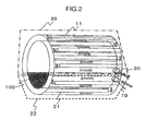
- FIG 2 is a drawing showing the housing 11, and illustration of the stator 2, the rotor 3, and the cooling frame 17 is omitted in the drawing.
- a flow passage wall 21 is formed in the housing 17, and the flow passage of the liquid coolant 101 is formed by this flow passage wall 21.
- this flow passage wall 21 is formed generally parallel to the direction of the rotation axis of the rotating electric machine 1, the liquid coolant 101 having flown in from the flow inlet 19 of the liquid coolant 101 flows in the direction of the rotation axis of the rotating electric machine 1.
- the liquid coolant 101 repeats to turn round at the end sections of the housing 11, goes round in the circumferential direction of the rotating electric machine 1, and flows to the outside of the rotating electric machine 1 at the flow outlet 20 of the liquid coolant 101.
- the housing 11 is divided into a portion 22 that cools the liquid coolant 100 and the stator core 4 and a portion 23 that cools the gas coolant and the stator core 4.
- the portion closer to the flow inlet 19 of the flow passage which is a portion of the front half when the flow passage is viewed along the direction the liquid coolant 101 flows is disposed, and the portion becomes a portion that mainly cools the liquid coolant 100.
- the portion closer to the flow outlet 20 of the flow passage which is a portion of the latter half when the flow passage is viewed along the direction the liquid coolant 101 flows is disposed, and the portion becomes a portion that mainly cools the gas coolant.
- the cooling frame in an aspect of the present invention is configured thus.
- the first feature point is that, to the portion 22 of the housing 11, the flow inlet 19 side of the flow passage which is the front half portion is disposed, and the front half portion becomes a portion that mainly cools the liquid coolant 100, whereas to the portion 23 of the housing 11, the flow outlet 20 side of the flow passage which is the latter half portion is disposed, and the latter half portion becomes a portion that mainly cools the gas coolant.
- the temperature of the liquid coolant 101 flowing in to the inside of the housing 11 is lower as the position is closer to the flow inlet, the liquid coolant 100 sealed inside the rotating electric machine 1 can be effectively cooled, cooling of the rotating electric machine 1 can be strengthened, and the rotating electric machine 1 can be miniaturized.
- the second feature point is that the direction of the flow passage 18 formed in the housing 11 is generally parallel to the direction of the rotation axis of the rotating electric machine 1.
- the pressure loss inside the housing 11 reduces.
- the flow rate of the liquid coolant 101 increases, cooling of the rotating electric machine 1 can be strengthened, and the rotating electric machine 1 can be miniaturized.
- the third feature point is that it is configured that the length in the axial direction of the flow passage 18 formed in the housing 11 becomes longer than the length in the axial direction of the stator core 4.
- cooling of the rotating electric machine 1 can be strengthened, and the rotating electric machine 1 can be miniaturized.
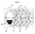
- Embodiment 2 that is the second aspect of the present invention will be described using FIG 3 .
- FIG. 3 is a drawing showing the housing 11 of the present embodiment, and illustration of the stator 2, the rotor 3, and the cooling frame 17 is omitted in the drawing.
- the point different from FIG 2 is that the direction of the flow passage 18 formed in the housing 11 is generally parallel to the circumferential direction of the rotating electric machine 1.
- this flow passage wall 21 is formed generally parallel to the circumferential direction of the rotating electric machine 1, the liquid coolant 101 having flown in from the flow inlet 19 of the liquid coolant 101 flows in the circumferential direction of the rotating electric machine 1.
- the liquid coolant 101 repeats to turn round at a turning round flow passage wall 24 formed in the housing 11, flows in the axial direction of the rotating electric machine 1, and flows to the flow passage 18 in the part upper than the turning round flow passage wall 24 of the rotating electric machine 1 at the end section in the axial direction of the rotating electric machine 1.
- the liquid coolant 101 flows in the circumferential direction, turns round at the turning round flow passage wall 24, flows to the end section in the axial direction of the rotating electric machine 1, and is made to flow out from the flow outlet 20 of the liquid coolant 101.
- the temperature at the flow inlet side and the flow outlet side of the liquid coolant 101 is equalized, thereby the temperature inside the rotating electric machine 1 can be equalized, thereby imbalance of the resistance value of the stator coils 5 among respective phases becomes less, and thereby drop of the output of the rotating electric machine 1 can be suppressed.
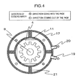
- Embodiment 3 that is the third aspect of the present invention will be described using FIG 4 .
- FIG. 4 is a sectional view in the circumferential direction of the housing 11 of the present embodiment. Also, in FIG 4 , illustration of the stator coils 5 and the rotor 3 is omitted. Here, the feature point is that the flow passage wall 21 of the housing 11 is formed in a portion the stator core 4 and the housing 11 do not contact each other.
- the flow passage wall 21 is formed in a portion the stator core 4 and the housing 11 do not contact each other, the area for heat conduction from the stator core 4 to the housing 11 can be effectively utilized, and therefore the stator core 4 can be more effectively cooled compared to a case the flow passage wall 21 is formed in a portion the stator core 4 and the housing 11 contact each other.
- cooling of the rotating electric machine 1 can be strengthened, and therefore the rotating electric machine 1 can be miniaturized.
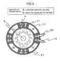
- Embodiment 4 that is the fourth aspect of the present invention will be described using FIG 5 .
- FIG 5 is a sectional view in the circumferential direction of the housing 11 of the present embodiment. Also, in FIG 5 , illustration of the stator coils 5 and the rotor 3 is omitted. The point different from FIG. 4 is that the interval of the flow passage wall 21 and the adjacent flow passage wall formed in the housing 11 is unequal interval.
- the contact area of the housing 11 and the liquid coolant 101 can be enlarged while effectively utilizing the area for heat conduction from the stator core 4 to the housing 11 because the flow passage wall 21 is formed in a portion the stator core 4 and the housing 11 do not contact each other, the cooling capacity of the housing 11 can be improved, thereby cooling of the rotating electric machine 1 can be strengthened, and therefore the rotating electric machine can be miniaturized.
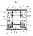
- Embodiment 5 that is the fifth aspect of the present invention will be described using FIG 6 .
- FIG 6 is a sectional view in the axial direction of the rotating electric machine 1 of the present embodiment.
- the point different from FIG 1 is that fins 25 are arranged on the inside diameter side of the housing 11.
- the heat removal amount of the liquid coolant 100 by the liquid coolant 101 can be increased, and therefore the temperature of the liquid coolant 100 can be lowered.
- cooling of the inside of the rotating electric machine 1 can be strengthened, and therefore the rotating electric machine can be miniaturized.
- Embodiment 6 that is the sixth aspect of the present invention will be described using FIG 7 .
- FIG 7 is a sectional view in the circumferential direction of the rotating electric machine 1 of the present embodiment. Also, FIG 7 is a drawing showing the housing 11 and the cooling frame 17, and illustration of the stator 2 and the rotor 3 is omitted in the drawing.
- the liquid coolant 101 having flown in from the flow inlet 19 flows in the axial direction of the rotating electric machine 1 by the flow passage wall 21 formed in the housing 11 in the axial direction of the rotating electric machine 1. Also, the liquid coolant 101 repeats to turn round after reaching the end section in the axial direction of the housing 11, and flows in the circumferential direction. In the present embodiment, it is configured that the liquid coolant 101 having flown in from the flow inlet 19 flows dividedly into two flow passages toward the flow outlet 20.
- the liquid coolant 100 can be effectively cooled by enlarging the area of the contact part of a flow passage portion where the temperature of the liquid coolant 101 is low and the liquid coolant 100, cooling of the inside of the rotating electric machine 1 can be strengthened, and the rotating electric machine 1 can be miniaturized.
- Embodiment 7 that is the seventh aspect of the present invention will be described using FIG 8 .
- FIG 8 is a sectional view in the axial direction of the rotating electric machine 1 of the present embodiment.
- a reservoir 26 for the liquid coolant 100 is arranged on the outside diameter side of the housing 11. Also, this reservoir 26 is disposed in the lower part of the rotating electric machine 1 to which direction the gravity is applied.
- the reservoir 26 is arranged, the area of the housing 11 cooling the liquid coolant 100 increases, and thereby the temperature of the liquid coolant 100 can be lowered.
- cooling of the inside of the rotating electric machine 1 can be strengthened, and therefore the rotating electric machine 1 can be miniaturized.
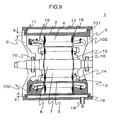
- Embodiment 8 that is the eighth aspect of the present invention will be described using FIG 9 .
- FIG 9 is a sectional view in the axial direction of the rotating electric machine 1 of the present embodiment.
- the point different from FIG 1 is that the thickness a of the housing 11 cooling the liquid coolant 100 and the stator core 4 is configured to be smaller than the thickness b of the housing 11 cooling the gas coolant 102 and the stator core 4.
- the present embodiment by reducing the thickness a of the housing 11 cooling the liquid coolant 100 and the stator core 4, the effect of cooling the liquid coolant 100 and the stator core 4 by the liquid coolant 101 is enhanced.
- cooling of the inside of the rotating electric machine 1 can be strengthened, and therefore the rotating electric machine 1 can be miniaturized.
- each embodiment described above is only an embodiment in implementing the present invention, and, with respect to the configuration of the rotating electric machine related to each embodiment described above, it is possible to replace a part thereof with other configuration, to delete a part thereof, and to add other configuration within a range not departing from the scope of the present invention. Also, it is needless to mention that the configuration of the rotating electric machine obtained by such replacement, deletion and addition is also included in the technical range of the present invention.
Landscapes
- Engineering & Computer Science (AREA)
- Power Engineering (AREA)
- Motor Or Generator Cooling System (AREA)
- Motor Or Generator Frames (AREA)
Applications Claiming Priority (1)
| Application Number | Priority Date | Filing Date | Title |
|---|---|---|---|
| JP2014007411A JP6368492B2 (ja) | 2014-01-20 | 2014-01-20 | 回転電機 |
Publications (3)
| Publication Number | Publication Date |
|---|---|
| EP2897259A2 true EP2897259A2 (de) | 2015-07-22 |
| EP2897259A3 EP2897259A3 (de) | 2016-04-27 |
| EP2897259B1 EP2897259B1 (de) | 2017-10-11 |
Family
ID=52354746
Family Applications (1)
| Application Number | Title | Priority Date | Filing Date |
|---|---|---|---|
| EP15000110.5A Active EP2897259B1 (de) | 2014-01-20 | 2015-01-16 | Rotierende Elektrische Maschine |
Country Status (3)
| Country | Link |
|---|---|
| US (1) | US9893593B2 (de) |
| EP (1) | EP2897259B1 (de) |
| JP (1) | JP6368492B2 (de) |
Cited By (1)
| Publication number | Priority date | Publication date | Assignee | Title |
|---|---|---|---|---|
| SE1951263A1 (en) * | 2019-11-05 | 2021-05-06 | Scania Cv Ab | An electric machine with an integrated heat exchanger |
Families Citing this family (16)
| Publication number | Priority date | Publication date | Assignee | Title |
|---|---|---|---|---|
| JP6398748B2 (ja) * | 2015-01-28 | 2018-10-03 | 株式会社デンソー | 回転電機 |
| JP2019024275A (ja) * | 2015-11-13 | 2019-02-14 | 株式会社日立製作所 | 回転電機 |
| JPWO2019021696A1 (ja) * | 2017-07-28 | 2020-05-28 | 日本電産株式会社 | モータ |
| KR102575713B1 (ko) * | 2017-12-04 | 2023-09-07 | 현대자동차주식회사 | 모터 냉각구조 |
| KR102041249B1 (ko) * | 2018-07-23 | 2019-11-27 | 하이윈 마이크로시스템 코포레이션 | 회전 전기 모터의 냉각 구조 |
| JP7088033B2 (ja) * | 2019-01-08 | 2022-06-21 | 株式会社デンソー | 回転電機 |
| FR3096844B1 (fr) * | 2019-06-03 | 2021-06-25 | Valeo Equip Electr Moteur | Machine electrique tournante munie d'une chambre de refroidissement |
| US12027943B2 (en) | 2019-08-05 | 2024-07-02 | Dana Heavy Vehicle Systems Group, Llc | Electric axle assembly |
| KR102153232B1 (ko) * | 2019-08-14 | 2020-09-07 | 현대자동차주식회사 | 냉각 시스템을 가지는 모터 |
| US12068668B2 (en) * | 2021-07-08 | 2024-08-20 | Honeywell International Inc. | Electric machine cooling |
| US12212219B2 (en) | 2021-07-08 | 2025-01-28 | Honeywell International Inc. | Electric machine cooling |
| DE102021121752A1 (de) | 2021-08-23 | 2023-02-23 | Bayerische Motoren Werke Aktiengesellschaft | Aktivteil mit schwerkraftgetriebener Kühleinrichtung, elektrische Maschine sowie Kraftfahrzeug |
| US12000664B2 (en) * | 2021-09-01 | 2024-06-04 | Eagle Technology, Llc | Heat exchanger |
| US11876434B2 (en) | 2021-09-03 | 2024-01-16 | Dana Limited | Air gap scavenging system for oil cooled electric motor |
| FR3129258A1 (fr) * | 2021-11-18 | 2023-05-19 | Moteurs Leroy-Somer | Machine électrique tournante refroidie par un liquide de refroidissement |
| US12273011B2 (en) * | 2023-02-06 | 2025-04-08 | Schaeffler Technologies AG & Co. KG | Electric motor shaft including inner helix pattern |
Citations (3)
| Publication number | Priority date | Publication date | Assignee | Title |
|---|---|---|---|---|
| JP2012191719A (ja) | 2011-03-09 | 2012-10-04 | Hitachi Constr Mach Co Ltd | 永久磁石式発電電動機および油圧ショベル用永久磁石式発電電動機 |
| JP2012191718A (ja) | 2011-03-09 | 2012-10-04 | Hitachi Constr Mach Co Ltd | 永久磁石式発電電動機および油圧ショベル用永久磁石式発電電動機 |
| JP2013162674A (ja) | 2012-02-07 | 2013-08-19 | Toshiba Industrial Products Manufacturing Corp | 回転電機 |
Family Cites Families (11)
| Publication number | Priority date | Publication date | Assignee | Title |
|---|---|---|---|---|
| JPH07872B2 (ja) | 1986-04-17 | 1995-01-11 | 株式会社クラレ | 皮革様シ−ト状物の表面仕上法 |
| JPH0670507A (ja) * | 1992-08-07 | 1994-03-11 | Nippondenso Co Ltd | 液冷型回転電機 |
| JP3501878B2 (ja) * | 1995-07-28 | 2004-03-02 | 日機装株式会社 | 冷却・潤滑系統を一体化した高速電動機 |
| US5859482A (en) * | 1997-02-14 | 1999-01-12 | General Electric Company | Liquid cooled electric motor frame |
| JPH10155257A (ja) * | 1997-03-28 | 1998-06-09 | Toyo Electric Mfg Co Ltd | 回転電機のフレームの液体冷却装置 |
| JP2007020333A (ja) * | 2005-07-08 | 2007-01-25 | Hitachi Industrial Equipment Systems Co Ltd | 液冷型の回転電機 |
| JP5135156B2 (ja) * | 2008-10-09 | 2013-01-30 | 東芝機械株式会社 | サーボモータ液冷構造および液冷モータ |
| WO2012167274A1 (en) * | 2011-06-03 | 2012-12-06 | Remy Technologies, Llc | Electric machine module cooling system and method |
| CN103650301B (zh) | 2011-07-21 | 2016-10-12 | 大金工业株式会社 | 电动马达及涡轮压缩机 |
| JP5706793B2 (ja) | 2011-09-20 | 2015-04-22 | 日立建機株式会社 | 発電電動機とこれを用いた電動車両 |
| TWI477039B (zh) * | 2011-11-23 | 2015-03-11 | Delta Electronics Inc | 冷卻套 |
-
2014
- 2014-01-20 JP JP2014007411A patent/JP6368492B2/ja active Active
-
2015
- 2015-01-16 EP EP15000110.5A patent/EP2897259B1/de active Active
- 2015-01-16 US US14/598,794 patent/US9893593B2/en active Active
Patent Citations (3)
| Publication number | Priority date | Publication date | Assignee | Title |
|---|---|---|---|---|
| JP2012191719A (ja) | 2011-03-09 | 2012-10-04 | Hitachi Constr Mach Co Ltd | 永久磁石式発電電動機および油圧ショベル用永久磁石式発電電動機 |
| JP2012191718A (ja) | 2011-03-09 | 2012-10-04 | Hitachi Constr Mach Co Ltd | 永久磁石式発電電動機および油圧ショベル用永久磁石式発電電動機 |
| JP2013162674A (ja) | 2012-02-07 | 2013-08-19 | Toshiba Industrial Products Manufacturing Corp | 回転電機 |
Cited By (2)
| Publication number | Priority date | Publication date | Assignee | Title |
|---|---|---|---|---|
| SE1951263A1 (en) * | 2019-11-05 | 2021-05-06 | Scania Cv Ab | An electric machine with an integrated heat exchanger |
| SE544011C2 (en) * | 2019-11-05 | 2021-11-02 | Scania Cv Ab | An electric machine with an integrated heat exchanger |
Also Published As
| Publication number | Publication date |
|---|---|
| US9893593B2 (en) | 2018-02-13 |
| EP2897259A3 (de) | 2016-04-27 |
| JP6368492B2 (ja) | 2018-08-01 |
| US20150207388A1 (en) | 2015-07-23 |
| JP2015136265A (ja) | 2015-07-27 |
| EP2897259B1 (de) | 2017-10-11 |
Similar Documents
| Publication | Publication Date | Title |
|---|---|---|
| EP2897259B1 (de) | Rotierende Elektrische Maschine | |
| US11791694B2 (en) | Stator for an electric motor and cooling thereof | |
| AU2010200958B2 (en) | Cooling system for rotating machine | |
| EP2632026B1 (de) | Kühlmantel für Axialströmungsmaschine | |
| JP6302736B2 (ja) | 回転電機 | |
| US10707726B2 (en) | Cooling structure for dynamo-electric machine | |
| US11387725B2 (en) | Integrated heat dissipative structure for electric machine | |
| US9419498B2 (en) | Rotary electric machine | |
| CN109450128B (zh) | 一种电机定子和具有该电机定子的油冷电机 | |
| JP6676668B2 (ja) | 回転電機のロータ及び回転電機 | |
| CN115224879A (zh) | 用于永久磁体马达内部的转子冷却组件和方法 | |
| EP3764524B1 (de) | Dynamo-elektrische maschine | |
| EP3716448A1 (de) | Endwindungskühlung | |
| JP2018207673A (ja) | 回転電機 | |
| CN105391200A (zh) | 全封闭旋转电机 | |
| JP6247555B2 (ja) | 回転電機 | |
| JP6212998B2 (ja) | 回転機および回転機の製造方法 | |
| JP2017050913A (ja) | 回転電機 | |
| JP7125864B2 (ja) | 回転電機 | |
| JP2013192339A (ja) | 誘導電動機 | |
| JP5892091B2 (ja) | マルチギャップ型回転電機 | |
| JP2019201521A (ja) | 回転機械 | |
| KR101547580B1 (ko) | 전동기의 냉각장치 | |
| KR20140038598A (ko) | 발전기 또는 전동기의 냉각구조 | |
| JP7192488B2 (ja) | モータ |
Legal Events
| Date | Code | Title | Description |
|---|---|---|---|
| PUAI | Public reference made under article 153(3) epc to a published international application that has entered the european phase |
Free format text: ORIGINAL CODE: 0009012 |
|
| 17P | Request for examination filed |
Effective date: 20150512 |
|
| AK | Designated contracting states |
Kind code of ref document: A2 Designated state(s): AL AT BE BG CH CY CZ DE DK EE ES FI FR GB GR HR HU IE IS IT LI LT LU LV MC MK MT NL NO PL PT RO RS SE SI SK SM TR |
|
| AX | Request for extension of the european patent |
Extension state: BA ME |
|
| PUAL | Search report despatched |
Free format text: ORIGINAL CODE: 0009013 |
|
| AK | Designated contracting states |
Kind code of ref document: A3 Designated state(s): AL AT BE BG CH CY CZ DE DK EE ES FI FR GB GR HR HU IE IS IT LI LT LU LV MC MK MT NL NO PL PT RO RS SE SI SK SM TR |
|
| AX | Request for extension of the european patent |
Extension state: BA ME |
|
| RIC1 | Information provided on ipc code assigned before grant |
Ipc: H02K 9/19 20060101ALI20160323BHEP Ipc: H02K 5/20 20060101AFI20160323BHEP Ipc: H02K 9/08 20060101ALI20160323BHEP |
|
| RBV | Designated contracting states (corrected) |
Designated state(s): AL AT BE BG CH CY CZ DE DK EE ES FI FR GB GR HR HU IE IS IT LI LT LU LV MC MK MT NL NO PL PT RO RS SE SI SK SM TR |
|
| GRAP | Despatch of communication of intention to grant a patent |
Free format text: ORIGINAL CODE: EPIDOSNIGR1 |
|
| STAA | Information on the status of an ep patent application or granted ep patent |
Free format text: STATUS: GRANT OF PATENT IS INTENDED |
|
| INTG | Intention to grant announced |
Effective date: 20170421 |
|
| RIN1 | Information on inventor provided before grant (corrected) |
Inventor name: KINOSHITA, HIROTAKA Inventor name: SUGIMOTO, SHINJI Inventor name: KORI, DAISUKE Inventor name: KANAZAWA, YUJI |
|
| GRAS | Grant fee paid |
Free format text: ORIGINAL CODE: EPIDOSNIGR3 |
|
| GRAA | (expected) grant |
Free format text: ORIGINAL CODE: 0009210 |
|
| STAA | Information on the status of an ep patent application or granted ep patent |
Free format text: STATUS: THE PATENT HAS BEEN GRANTED |
|
| AK | Designated contracting states |
Kind code of ref document: B1 Designated state(s): AL AT BE BG CH CY CZ DE DK EE ES FI FR GB GR HR HU IE IS IT LI LT LU LV MC MK MT NL NO PL PT RO RS SE SI SK SM TR |
|
| REG | Reference to a national code |
Ref country code: GB Ref legal event code: FG4D |
|
| REG | Reference to a national code |
Ref country code: CH Ref legal event code: EP |
|
| REG | Reference to a national code |
Ref country code: IE Ref legal event code: FG4D |
|
| REG | Reference to a national code |
Ref country code: AT Ref legal event code: REF Ref document number: 936831 Country of ref document: AT Kind code of ref document: T Effective date: 20171115 |
|
| REG | Reference to a national code |
Ref country code: DE Ref legal event code: R096 Ref document number: 602015005208 Country of ref document: DE |
|
| REG | Reference to a national code |
Ref country code: NL Ref legal event code: MP Effective date: 20171011 |
|
| REG | Reference to a national code |
Ref country code: LT Ref legal event code: MG4D |
|
| REG | Reference to a national code |
Ref country code: AT Ref legal event code: MK05 Ref document number: 936831 Country of ref document: AT Kind code of ref document: T Effective date: 20171011 |
|
| PG25 | Lapsed in a contracting state [announced via postgrant information from national office to epo] |
Ref country code: NL Free format text: LAPSE BECAUSE OF FAILURE TO SUBMIT A TRANSLATION OF THE DESCRIPTION OR TO PAY THE FEE WITHIN THE PRESCRIBED TIME-LIMIT Effective date: 20171011 |
|
| PG25 | Lapsed in a contracting state [announced via postgrant information from national office to epo] |
Ref country code: FI Free format text: LAPSE BECAUSE OF FAILURE TO SUBMIT A TRANSLATION OF THE DESCRIPTION OR TO PAY THE FEE WITHIN THE PRESCRIBED TIME-LIMIT Effective date: 20171011 Ref country code: NO Free format text: LAPSE BECAUSE OF FAILURE TO SUBMIT A TRANSLATION OF THE DESCRIPTION OR TO PAY THE FEE WITHIN THE PRESCRIBED TIME-LIMIT Effective date: 20180111 Ref country code: ES Free format text: LAPSE BECAUSE OF FAILURE TO SUBMIT A TRANSLATION OF THE DESCRIPTION OR TO PAY THE FEE WITHIN THE PRESCRIBED TIME-LIMIT Effective date: 20171011 Ref country code: LT Free format text: LAPSE BECAUSE OF FAILURE TO SUBMIT A TRANSLATION OF THE DESCRIPTION OR TO PAY THE FEE WITHIN THE PRESCRIBED TIME-LIMIT Effective date: 20171011 Ref country code: SE Free format text: LAPSE BECAUSE OF FAILURE TO SUBMIT A TRANSLATION OF THE DESCRIPTION OR TO PAY THE FEE WITHIN THE PRESCRIBED TIME-LIMIT Effective date: 20171011 |
|
| PG25 | Lapsed in a contracting state [announced via postgrant information from national office to epo] |
Ref country code: IS Free format text: LAPSE BECAUSE OF FAILURE TO SUBMIT A TRANSLATION OF THE DESCRIPTION OR TO PAY THE FEE WITHIN THE PRESCRIBED TIME-LIMIT Effective date: 20180211 Ref country code: AT Free format text: LAPSE BECAUSE OF FAILURE TO SUBMIT A TRANSLATION OF THE DESCRIPTION OR TO PAY THE FEE WITHIN THE PRESCRIBED TIME-LIMIT Effective date: 20171011 Ref country code: RS Free format text: LAPSE BECAUSE OF FAILURE TO SUBMIT A TRANSLATION OF THE DESCRIPTION OR TO PAY THE FEE WITHIN THE PRESCRIBED TIME-LIMIT Effective date: 20171011 Ref country code: HR Free format text: LAPSE BECAUSE OF FAILURE TO SUBMIT A TRANSLATION OF THE DESCRIPTION OR TO PAY THE FEE WITHIN THE PRESCRIBED TIME-LIMIT Effective date: 20171011 Ref country code: GR Free format text: LAPSE BECAUSE OF FAILURE TO SUBMIT A TRANSLATION OF THE DESCRIPTION OR TO PAY THE FEE WITHIN THE PRESCRIBED TIME-LIMIT Effective date: 20180112 Ref country code: BG Free format text: LAPSE BECAUSE OF FAILURE TO SUBMIT A TRANSLATION OF THE DESCRIPTION OR TO PAY THE FEE WITHIN THE PRESCRIBED TIME-LIMIT Effective date: 20180111 Ref country code: LV Free format text: LAPSE BECAUSE OF FAILURE TO SUBMIT A TRANSLATION OF THE DESCRIPTION OR TO PAY THE FEE WITHIN THE PRESCRIBED TIME-LIMIT Effective date: 20171011 |
|
| REG | Reference to a national code |
Ref country code: DE Ref legal event code: R097 Ref document number: 602015005208 Country of ref document: DE |
|
| PG25 | Lapsed in a contracting state [announced via postgrant information from national office to epo] |
Ref country code: SK Free format text: LAPSE BECAUSE OF FAILURE TO SUBMIT A TRANSLATION OF THE DESCRIPTION OR TO PAY THE FEE WITHIN THE PRESCRIBED TIME-LIMIT Effective date: 20171011 Ref country code: CZ Free format text: LAPSE BECAUSE OF FAILURE TO SUBMIT A TRANSLATION OF THE DESCRIPTION OR TO PAY THE FEE WITHIN THE PRESCRIBED TIME-LIMIT Effective date: 20171011 Ref country code: DK Free format text: LAPSE BECAUSE OF FAILURE TO SUBMIT A TRANSLATION OF THE DESCRIPTION OR TO PAY THE FEE WITHIN THE PRESCRIBED TIME-LIMIT Effective date: 20171011 Ref country code: EE Free format text: LAPSE BECAUSE OF FAILURE TO SUBMIT A TRANSLATION OF THE DESCRIPTION OR TO PAY THE FEE WITHIN THE PRESCRIBED TIME-LIMIT Effective date: 20171011 |
|
| REG | Reference to a national code |
Ref country code: DE Ref legal event code: R119 Ref document number: 602015005208 Country of ref document: DE |
|
| PLBE | No opposition filed within time limit |
Free format text: ORIGINAL CODE: 0009261 |
|
| STAA | Information on the status of an ep patent application or granted ep patent |
Free format text: STATUS: NO OPPOSITION FILED WITHIN TIME LIMIT |
|
| PG25 | Lapsed in a contracting state [announced via postgrant information from national office to epo] |
Ref country code: RO Free format text: LAPSE BECAUSE OF FAILURE TO SUBMIT A TRANSLATION OF THE DESCRIPTION OR TO PAY THE FEE WITHIN THE PRESCRIBED TIME-LIMIT Effective date: 20171011 Ref country code: PL Free format text: LAPSE BECAUSE OF FAILURE TO SUBMIT A TRANSLATION OF THE DESCRIPTION OR TO PAY THE FEE WITHIN THE PRESCRIBED TIME-LIMIT Effective date: 20171011 Ref country code: SM Free format text: LAPSE BECAUSE OF FAILURE TO SUBMIT A TRANSLATION OF THE DESCRIPTION OR TO PAY THE FEE WITHIN THE PRESCRIBED TIME-LIMIT Effective date: 20171011 |
|
| REG | Reference to a national code |
Ref country code: CH Ref legal event code: PL |
|
| 26N | No opposition filed |
Effective date: 20180712 |
|
| PG25 | Lapsed in a contracting state [announced via postgrant information from national office to epo] |
Ref country code: LU Free format text: LAPSE BECAUSE OF NON-PAYMENT OF DUE FEES Effective date: 20180116 Ref country code: DE Free format text: LAPSE BECAUSE OF NON-PAYMENT OF DUE FEES Effective date: 20180801 Ref country code: FR Free format text: LAPSE BECAUSE OF NON-PAYMENT OF DUE FEES Effective date: 20180131 |
|
| REG | Reference to a national code |
Ref country code: IE Ref legal event code: MM4A |
|
| REG | Reference to a national code |
Ref country code: FR Ref legal event code: ST Effective date: 20180928 |
|
| REG | Reference to a national code |
Ref country code: BE Ref legal event code: MM Effective date: 20180131 |
|
| PG25 | Lapsed in a contracting state [announced via postgrant information from national office to epo] |
Ref country code: CH Free format text: LAPSE BECAUSE OF NON-PAYMENT OF DUE FEES Effective date: 20180131 Ref country code: SI Free format text: LAPSE BECAUSE OF FAILURE TO SUBMIT A TRANSLATION OF THE DESCRIPTION OR TO PAY THE FEE WITHIN THE PRESCRIBED TIME-LIMIT Effective date: 20171011 Ref country code: LI Free format text: LAPSE BECAUSE OF NON-PAYMENT OF DUE FEES Effective date: 20180131 Ref country code: BE Free format text: LAPSE BECAUSE OF NON-PAYMENT OF DUE FEES Effective date: 20180131 |
|
| PG25 | Lapsed in a contracting state [announced via postgrant information from national office to epo] |
Ref country code: IE Free format text: LAPSE BECAUSE OF NON-PAYMENT OF DUE FEES Effective date: 20180116 |
|
| PG25 | Lapsed in a contracting state [announced via postgrant information from national office to epo] |
Ref country code: MC Free format text: LAPSE BECAUSE OF FAILURE TO SUBMIT A TRANSLATION OF THE DESCRIPTION OR TO PAY THE FEE WITHIN THE PRESCRIBED TIME-LIMIT Effective date: 20171011 |
|
| PG25 | Lapsed in a contracting state [announced via postgrant information from national office to epo] |
Ref country code: MT Free format text: LAPSE BECAUSE OF NON-PAYMENT OF DUE FEES Effective date: 20180116 |
|
| PG25 | Lapsed in a contracting state [announced via postgrant information from national office to epo] |
Ref country code: TR Free format text: LAPSE BECAUSE OF FAILURE TO SUBMIT A TRANSLATION OF THE DESCRIPTION OR TO PAY THE FEE WITHIN THE PRESCRIBED TIME-LIMIT Effective date: 20171011 |
|
| PG25 | Lapsed in a contracting state [announced via postgrant information from national office to epo] |
Ref country code: PT Free format text: LAPSE BECAUSE OF FAILURE TO SUBMIT A TRANSLATION OF THE DESCRIPTION OR TO PAY THE FEE WITHIN THE PRESCRIBED TIME-LIMIT Effective date: 20171011 |
|
| PG25 | Lapsed in a contracting state [announced via postgrant information from national office to epo] |
Ref country code: CY Free format text: LAPSE BECAUSE OF FAILURE TO SUBMIT A TRANSLATION OF THE DESCRIPTION OR TO PAY THE FEE WITHIN THE PRESCRIBED TIME-LIMIT Effective date: 20171011 Ref country code: HU Free format text: LAPSE BECAUSE OF FAILURE TO SUBMIT A TRANSLATION OF THE DESCRIPTION OR TO PAY THE FEE WITHIN THE PRESCRIBED TIME-LIMIT; INVALID AB INITIO Effective date: 20150116 Ref country code: MK Free format text: LAPSE BECAUSE OF NON-PAYMENT OF DUE FEES Effective date: 20171011 |
|
| PG25 | Lapsed in a contracting state [announced via postgrant information from national office to epo] |
Ref country code: AL Free format text: LAPSE BECAUSE OF FAILURE TO SUBMIT A TRANSLATION OF THE DESCRIPTION OR TO PAY THE FEE WITHIN THE PRESCRIBED TIME-LIMIT Effective date: 20171011 |
|
| PGFP | Annual fee paid to national office [announced via postgrant information from national office to epo] |
Ref country code: GB Payment date: 20241128 Year of fee payment: 11 |
|
| PGFP | Annual fee paid to national office [announced via postgrant information from national office to epo] |
Ref country code: IT Payment date: 20241210 Year of fee payment: 11 |