EP2896482A2 - Feinschleifrad und Herstellungsverfahren dafür - Google Patents
Feinschleifrad und Herstellungsverfahren dafür Download PDFInfo
- Publication number
- EP2896482A2 EP2896482A2 EP15150378.6A EP15150378A EP2896482A2 EP 2896482 A2 EP2896482 A2 EP 2896482A2 EP 15150378 A EP15150378 A EP 15150378A EP 2896482 A2 EP2896482 A2 EP 2896482A2
- Authority
- EP
- European Patent Office
- Prior art keywords
- mesh
- grinding wheel
- abrasive mixture
- reinforcing mesh
- layer
- Prior art date
- Legal status (The legal status is an assumption and is not a legal conclusion. Google has not performed a legal analysis and makes no representation as to the accuracy of the status listed.)
- Withdrawn
Links
- 238000000227 grinding Methods 0.000 title claims abstract description 106
- 238000000034 method Methods 0.000 title claims description 19
- 239000000203 mixture Substances 0.000 claims abstract description 109
- 230000003014 reinforcing effect Effects 0.000 claims abstract description 90
- 238000000151 deposition Methods 0.000 claims description 16
- 238000003825 pressing Methods 0.000 claims description 13
- 230000000284 resting effect Effects 0.000 claims description 9
- 238000003780 insertion Methods 0.000 claims description 7
- 230000037431 insertion Effects 0.000 claims description 7
- 230000000630 rising effect Effects 0.000 claims description 7
- 239000010410 layer Substances 0.000 description 68
- 239000003082 abrasive agent Substances 0.000 description 16
- 230000002787 reinforcement Effects 0.000 description 14
- 239000002245 particle Substances 0.000 description 11
- 239000011347 resin Substances 0.000 description 11
- 229920005989 resin Polymers 0.000 description 11
- 230000000994 depressogenic effect Effects 0.000 description 6
- 238000004519 manufacturing process Methods 0.000 description 6
- 230000008901 benefit Effects 0.000 description 5
- 229910052593 corundum Inorganic materials 0.000 description 5
- 239000010431 corundum Substances 0.000 description 5
- 239000011159 matrix material Substances 0.000 description 5
- 239000000843 powder Substances 0.000 description 5
- 239000011230 binding agent Substances 0.000 description 4
- 238000010438 heat treatment Methods 0.000 description 4
- 239000000463 material Substances 0.000 description 4
- 238000006116 polymerization reaction Methods 0.000 description 4
- 238000005520 cutting process Methods 0.000 description 3
- 239000007788 liquid Substances 0.000 description 3
- 230000002093 peripheral effect Effects 0.000 description 3
- 230000009471 action Effects 0.000 description 2
- 239000000654 additive Substances 0.000 description 2
- 239000000919 ceramic Substances 0.000 description 2
- 230000000295 complement effect Effects 0.000 description 2
- 150000001875 compounds Chemical class 0.000 description 2
- 239000003822 epoxy resin Substances 0.000 description 2
- 230000001747 exhibiting effect Effects 0.000 description 2
- 239000000945 filler Substances 0.000 description 2
- 239000011888 foil Substances 0.000 description 2
- 229910052751 metal Inorganic materials 0.000 description 2
- 150000002894 organic compounds Chemical group 0.000 description 2
- ISWSIDIOOBJBQZ-UHFFFAOYSA-N phenol group Chemical group C1(=CC=CC=C1)O ISWSIDIOOBJBQZ-UHFFFAOYSA-N 0.000 description 2
- 229920000647 polyepoxide Polymers 0.000 description 2
- 229920001721 polyimide Polymers 0.000 description 2
- 239000009719 polyimide resin Substances 0.000 description 2
- 239000004753 textile Substances 0.000 description 2
- 235000013311 vegetables Nutrition 0.000 description 2
- OKTJSMMVPCPJKN-UHFFFAOYSA-N Carbon Chemical compound [C] OKTJSMMVPCPJKN-UHFFFAOYSA-N 0.000 description 1
- 229920000271 Kevlar® Polymers 0.000 description 1
- 230000001070 adhesive effect Effects 0.000 description 1
- 230000015572 biosynthetic process Effects 0.000 description 1
- 229910021418 black silicon Inorganic materials 0.000 description 1
- 229910052799 carbon Inorganic materials 0.000 description 1
- 230000001419 dependent effect Effects 0.000 description 1
- 230000005611 electricity Effects 0.000 description 1
- 239000005007 epoxy-phenolic resin Substances 0.000 description 1
- 239000004744 fabric Substances 0.000 description 1
- 239000012530 fluid Substances 0.000 description 1
- 239000003365 glass fiber Substances 0.000 description 1
- 239000003292 glue Substances 0.000 description 1
- LNEPOXFFQSENCJ-UHFFFAOYSA-N haloperidol Chemical group C1CC(O)(C=2C=CC(Cl)=CC=2)CCN1CCCC(=O)C1=CC=C(F)C=C1 LNEPOXFFQSENCJ-UHFFFAOYSA-N 0.000 description 1
- 230000006872 improvement Effects 0.000 description 1
- 238000011065 in-situ storage Methods 0.000 description 1
- 230000001788 irregular Effects 0.000 description 1
- 230000002427 irreversible effect Effects 0.000 description 1
- 239000004761 kevlar Substances 0.000 description 1
- 239000002184 metal Substances 0.000 description 1
- 239000007769 metal material Substances 0.000 description 1
- 238000003801 milling Methods 0.000 description 1
- 238000012986 modification Methods 0.000 description 1
- 230000004048 modification Effects 0.000 description 1
- 239000005011 phenolic resin Substances 0.000 description 1
- 229920001568 phenolic resin Polymers 0.000 description 1
- 229920000642 polymer Polymers 0.000 description 1
- 230000000379 polymerizing effect Effects 0.000 description 1
- 238000002360 preparation method Methods 0.000 description 1
- 230000008569 process Effects 0.000 description 1
- 239000010979 ruby Substances 0.000 description 1
- 229910001750 ruby Inorganic materials 0.000 description 1
- 239000004576 sand Substances 0.000 description 1
- 230000035939 shock Effects 0.000 description 1
- HBMJWWWQQXIZIP-UHFFFAOYSA-N silicon carbide Chemical compound [Si+]#[C-] HBMJWWWQQXIZIP-UHFFFAOYSA-N 0.000 description 1
- 239000002356 single layer Substances 0.000 description 1
- 239000007787 solid Substances 0.000 description 1
- 239000002904 solvent Substances 0.000 description 1
- 238000003892 spreading Methods 0.000 description 1
- 230000007480 spreading Effects 0.000 description 1
- 238000005728 strengthening Methods 0.000 description 1
- 229920002994 synthetic fiber Polymers 0.000 description 1
Images


Classifications
-
- B—PERFORMING OPERATIONS; TRANSPORTING
- B24—GRINDING; POLISHING
- B24D—TOOLS FOR GRINDING, BUFFING OR SHARPENING
- B24D5/00—Bonded abrasive wheels, or wheels with inserted abrasive blocks, designed for acting only by their periphery; Bushings or mountings therefor
- B24D5/02—Wheels in one piece
- B24D5/04—Wheels in one piece with reinforcing means
-
- B—PERFORMING OPERATIONS; TRANSPORTING
- B24—GRINDING; POLISHING
- B24D—TOOLS FOR GRINDING, BUFFING OR SHARPENING
- B24D18/00—Manufacture of grinding tools or other grinding devices, e.g. wheels, not otherwise provided for
- B24D18/0009—Manufacture of grinding tools or other grinding devices, e.g. wheels, not otherwise provided for using moulds or presses
-
- B—PERFORMING OPERATIONS; TRANSPORTING
- B24—GRINDING; POLISHING
- B24D—TOOLS FOR GRINDING, BUFFING OR SHARPENING
- B24D18/00—Manufacture of grinding tools or other grinding devices, e.g. wheels, not otherwise provided for
- B24D18/0054—Manufacture of grinding tools or other grinding devices, e.g. wheels, not otherwise provided for by impressing abrasive powder in a matrix
-
- B—PERFORMING OPERATIONS; TRANSPORTING
- B24—GRINDING; POLISHING
- B24D—TOOLS FOR GRINDING, BUFFING OR SHARPENING
- B24D3/00—Physical features of abrasive bodies, or sheets, e.g. abrasive surfaces of special nature; Abrasive bodies or sheets characterised by their constituents
- B24D3/001—Physical features of abrasive bodies, or sheets, e.g. abrasive surfaces of special nature; Abrasive bodies or sheets characterised by their constituents the constituent being used as supporting member
- B24D3/002—Flexible supporting members, e.g. paper, woven, plastic materials
-
- B—PERFORMING OPERATIONS; TRANSPORTING
- B24—GRINDING; POLISHING
- B24D—TOOLS FOR GRINDING, BUFFING OR SHARPENING
- B24D7/00—Bonded abrasive wheels, or wheels with inserted abrasive blocks, designed for acting otherwise than only by their periphery, e.g. by the front face; Bushings or mountings therefor
- B24D7/02—Wheels in one piece
- B24D7/04—Wheels in one piece with reinforcing means
Definitions
- the present invention relates to a grinding wheel having a depressed or flat centre and a method for production of the grinding wheels.
- the present invention relates to a finishing grinding wheel and a method for realizing the grinding wheel.
- the prior art includes disc-shaped abrasive grinding wheels having a depressed or flat centre, conical, semi-flexible and exhibit an external diameter substantially comprised between 30 and 230 mm, especially used on high-speed portable electric grinding wheels, powered by electricity or compressed air (60-100 m/s peripheral velocity), also known as finishing grinding wheels, for carrying out grinding and/or cutting operations, which are essentially constituted by an abrasive mixture reinforced by armatures constituted by one or more textile meshes, on or more annular metal elements, commonly known as rings, which delimit the fastening hole of the grinding wheel to the shaft of the milling machine, and possibly by a paper label or another identifying plate adhering to one of the two faces of the grinding wheel (usually the convex face).
- the abrasive mixture is generally constituted by grains of abrasive material (light green, dark green or black silicon carbide, corundum, zircon-modified corundum, semi-friable, red-brown, white, pink, ruby, ceramicated, mono-crystalline, sol-gel abrasives or sintered ceramics or others besides) having predefined particle size (normally measured in mesh) which are mixed with resins, for example phenolic, liquid and/or in powder form and possibly modified with epoxy resins, and/or others, possibly modified with organic compounds and/or vegetable or synthetic compounds, and other types of polyimide resins etc., and with additives and fillers.
- resins for example phenolic, liquid and/or in powder form and possibly modified with epoxy resins, and/or others, possibly modified with organic compounds and/or vegetable or synthetic compounds, and other types of polyimide resins etc., and with additives and fillers.
- the reinforcing meshes are normally glass-fibre fabrics but other types of fibres could be used, such as carbon, Kevlar or others; the textile meshes, around 1.5 m in height, are first immersed in a solution of liquid resins and solvents, squeezed between pairs of rollers and dried in appropriate ovens internally of which the resin dries without polymerizing (polymerization is then completed in the baking oven together with the baking of the grinder).
- the meshes thus-impregnated with resin and dried, are used for the blanking (or other cutting method) of the mesh discs required for reinforcing the grinding wheels.
- the meshes can possibly be pre-glued to a paper sheet or a slim polymer sheet, or also to the labels.
- the annular elements defining and delimiting the attaching hole of the grinding wheel are constituted by a small circular crown plate, or a plate of another shape, such as for example square or polygonal, from the internal hole of which a hollow cylindrical or non-cylindrical appendage extends; the plate adheres to one of the two faces of the grinding wheel, while the hollow appendage inserts in the hole of the grinding wheel, delimiting the internal wall.
- the labels are made of paper or foil or another synthetic material and they normally have a circular crown shape (though they could have a different shape) and can occupy either the whole face of the grinding wheel or a limited area of the face to which the identifying and informative data of the grinding wheel can be attached.
- Grinding wheels are produced by pressing in dies constituted by a ring in which a superiorly-open forming cavity is housed, known as a female, and by a complementary punch, known as a male.
- a concave recess is formed in the central portion of the bottom of the forming cavity (the female), from which concave recess a pin rises for definition of the attachment hole of the grinding wheel; a protrusion is fashioned in the central portion of the punch (the male), which protrusion couples with the recess and internally of which a hole is afforded in which the pin is inserted during the active pressing step.
- the method currently known for the production of grinding wheels consists essentially of inserting a first annular element (washer) on the pin, defining the attachment hole of the grinding wheel, the plate of the element resting on the bottom of the concave recess and the cylindrical appendage facing upwards, and of resting either a first reinforcing mesh or a suitable paper label on the bottom of the forming cavity, the reinforcing mesh being provided with glued paper having a function of supporting the mixture; further consisting in depositing a first layer of abrasive mixture, in depositing for example a second reinforcement mesh, in inserting, on the pin, an eventual second annular element (washer) defining the hole opposite the first, and in pressing, with the punch (male), at pressures in the order of 100-300 Kg/cm2 and releasing the pressed wheel from the die.
- a first annular element washer
- successive layers of abrasive mixture alternated with supplementary reinforcement meshes can be realised on the first layer of abrasive mixture deposited.
- the first mesh placed i.e. the lowest mesh or the "backbone", the mesh which in the case of a depressed-centre wheel, is located on the outside of the grinding wheel, can be placed directly on the bottom of the forming cavity of the matrix coupled to a sheet of paper material, or by interposing an annular paper label or a like element between the bottom of the forming cavity and the first mesh.
- the label or the bottom of the forming cavity performs the function of containment and support of the abrasive mixture deposited internally of the forming cavity, and in order to perform this function, must exhibit an adequate rig id ity.
- the pressed grinding wheel once removed from the die is subsequently subjected to heating at a temperature slowly rising from 80°C to 125°C; in these conditions the resins of the abrasive mixture and the resins impregnating the reinforcement mesh or meshes become fluid, “merging” together and “interpenetrating”; in this way the mixture adheres to the mesh or meshes and together with them creates a single block.
- a subsequent re-heating of up to 180-190°C determines the process of irreversible polymerization of the resin.
- a first drawback consists in the fact that, in a case of production of depressed-centre grinding wheels, during the depositing of the abrasive mixture internally of the cavity, at least the central portion of the first reinforcing mesh or the labels rested on the bottom of the cavity, which portion is at the concave recess of the cavity itself, yields and flexes below the weight of the abrasive mixture deposited, which is a cause of undesired variations of density and thickness of the central portion of the grinding wheel with respect to the peripheral portion thereof.
- a further drawback of the known methods consists in the fact that the adhesion of the first reinforcing mesh, the one deposited on the bottom of the forming cavity, to the abrasive mixture, is limited and incomplete; this is due both to the fact that the abrasive mixture adheres to a single face (the upper face) of the first reinforcing mesh or, at most, penetrates into the mesh openings and glues the flanks of the mesh wired, leaving the face resting on the bottom of the cavity and/or on the label uncovered, and also is due to the very limited adhesive properties of phenolic or phenol-epoxy resins normally used.
- the first reinforcing mesh is a mesh glued to a slim paper sheet; in this case, the sheet obstructs the spreading of the abrasive mixture to below the links of the mesh, preventing the mesh from sinking into the grinding wheel.
- a method aimed at achieving this result could be to deposit, on the bottom of the cavity of the forming die, a thin layer of abrasive mixture on which to rest the first mesh.
- a further drawback encountered in this solution is the fact that the reinforcing mesh is supported at discrete points thereof in the central area; therefore the periphery of the mesh, under the weight of the abrasive mixture before it penetrates the spaces between the meshes of the first reinforcing mesh and goes to rest on the bottom, defining a support layer for the mesh, can flex and thus lose the substantial planarity thereof.
- the bottom of the forming cavity of the die is machined to define respective projections on which the reinforcing mesh rests; this not only increases the cost of the die, but also defines cavities in the finished grinding wheel.
- An aim of the present invention is to obviate the above-mentioned drawbacks in the prior art, with a solution that is simple, rational and relatively inexpensive.
- the invention discloses a grinding wheel which comprises at least a first reinforcing mesh completely incorporated into at least a first layer of abrasive mixture and at least a support element in contact with the first reinforcing mesh.
- the reinforcing element comprises an auxiliary mesh provided with a face in direct contact with the first reinforcing mesh.
- the first reinforcing mesh i.e. the back strengthening mesh or "backbone”
- the back strengthening mesh is completely incorporated into the first layer of abrasive mixture which defines the backbone of the grinding wheel, and this makes the structure significantly more solid and resistant.
- a further face, i.e. the rear backbone face, of the auxiliary mesh at least partially emerges (as it is substantially level with the rear face of the first layer of abrasive mixture) from the first layer of abrasive mixture.
- the auxiliary mesh preferably exhibits mesh passages that are larger than those of the first reinforcing mesh.
- the auxiliary mesh advantageously exhibits mesh passages comprised between 1x1 cm and 3x3 cm, preferably 2x2 cm.
- the auxiliary mesh exhibits a thickness substantially comprised between 0.5 and 2 mm, preferably 1 mm.
- the maximum thickness can be obtained at only the nodes of the auxiliary mesh, or at the whole surface of the auxiliary mesh, or in other points distributed in the surface of the auxiliary mesh.
- the first layer of abrasive mixture exhibits a rear portion (back portion) that is sufficiently thick to incorporate the first reinforcing mesh and to prevent any detachments of material in use.
- the auxiliary mesh is advantageously substantially disc-shaped with an external diameter that is substantially comprised between 0.7 and 1.0 times the external diameter of the abrasive mixture.
- auxiliary mesh together with the single reinforcing mesh (the first reinforcing mesh) further enables creating, in practice, two (semi)layers of "backbone" abrasive mixture, respectively a front portion and a rear portion to the first reinforcing mesh with a simple depositing of abrasive mixture (because the grains pass below the suspended reinforcing mesh and create a rear portion between the links of the meshes of the auxiliary mesh).
- This fact is particularly advantageous and appreciable in the grinding wheels realised using forming plants provided with only one or two depositing stations of abrasive mixture (for example, one with fine grains for the back and a coarser grain for the front portion of the grinding wheel), as the number of layers the grinding wheel is made up of is increased with a same number of depositing operations.
- the grinding wheel comprises at least a second reinforcing mesh incorporated in a respective second layer of abrasive mixture (obtained by depositing a second abrasive mixture, for example coarser, for example in a second depositing station), in which at least one from between the second reinforcing mesh and the second layer of abrasive mixture is in contact with the first layer of abrasive mixture on the opposite side with respect to the auxiliary mesh.
- a method for realising a grinding wheel which comprises steps of:
- the support element comprises an auxiliary mesh a first face of which is supported restingly on a bottom wall of the forming cavity and the second face of which is in contact with the first reinforcing mesh in such a way as to maintain the first reinforcing mesh raised with respect to the bottom wall.
- the laying of the first reinforcing mesh advantageously precedes the depositing of the abrasive mixture so as to realise the first layer of abrasive mixture internally of the cavity, the abrasive mixture in practice being distributed in the forming cavity in a first portion and in a second portion respectively lower and upper with respect to the first reinforcing mesh so as to incorporate the first reinforcing mesh internally thereof.
- the second portion that penetrates between the mesh passages of the first reinforcing mesh is arranged between the links of the auxiliary mesh, creating a layer that posteriorly covers the whole first reinforcing mesh.
- a further step is included of arranging a label (exhibiting a diameter equal to or smaller than the internal diameter of the forming cavity, for example between 70% and 90% thereof) on the bottom wall of the forming cavity at a same time as (for example, if glued or in any case rested) or before insertion of the auxiliary mesh in the forming cavity.
- the forming cavity advantageously comprises at least a forming core of the attaching hole of the grinding wheel, rising from the bottom wall of the forming cavity and centred in the forming cavity, the auxiliary mesh and the first reinforcing mesh (as well as the label, if present) being inserted substantially coaxially on the forming core.
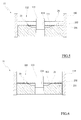
- reference numeral 10 denotes in its entirety a die for forming grinding wheels (with depressed or flat centres), generally denoted by reference number 20.
- the die 10 comprises a die matrix 11 positionable opposite a punch 12 for forming the grinding wheel 20.
- the die matrix 11 for example, comprises a cylindrical sleeve 110 inferiorly closed by a bottom wall 111.
- the bottom wall 111 comprises a disc-shaped body and a circumferential base for example made of a metal material able, for example, to be inserted substantially snugly internally of the cylindrical sleeve 110.
- the bottom wall 111 and the cylindrical sleeve 110 delimit a forming chamber 112 open at a top thereof.
- the bottom wall 111 is advantageously associated slidably with respect to the cylindrical sleeve 110 so that the internal volume of the forming chamber 112 can be varied by changing the axial position of the bottom wall 111 with respect to the cylindrical sleeve 110.
- the bottom wall 111 centrally exhibits a centring pin 113 rising from the upper face thereof and coaxial with the cylindrical sleeve 110.
- centring pin 113 is inserted in a central hole 114 made in the bottom wall 111 and fixed therein.
- the upper face of the bottom wall 111 can be substantially planar if a flat grinding wheel 20 is to be manufactured (or a semi-finished piece which will then be deformed so as to form a grinding wheel 20 with a depressed, "dimpled" centre 100).
- the upper face of the bottom wall 111 preferably comprises a central depression that is coaxial to the bottom wall and defines a central dimple, so as to overall define a concave bottom wall 111 for forming depressed-centre grinding wheels 20.
- the bottom wall 111 defines a rest plane for the grinding wheel 20 to be formed that is substantially perpendicular to the axis of the cylindrical sleeve 110.
- the punch 12 for example, comprises an annular/disc-shaped body, an external diameter of which is substantially equal to the external diameter of the bottom wall 111 of the die matrix 11 (i.e. a little smaller than the internal diameter of the cylindrical sleeve 110), so as to be insertable substantially snugly in the cylindrical sleeve 110 and to be superposed on the bottom wall.
- the punch 12 comprises a complementary shape to the bottom wall 111.
- the punch 12 can be realized as a monolithic body or by two annular concentric and separate bodies able to be axially activated independently in order for independent outer periphery and inner formation of the grinding wheel 20 to be achieved.
- the punch 12 and the bottom wall 111 are movable towards/away from each other, respectively for closing/opening the forming cavity 112, as is known to a technical expert in the sector.
- the grinding wheel 20 comprises a disc-shaped body (planar or preferably having a depressed centre) provided with a central attachment hole 200, which is associated, substantially coaxially, to the free end of a rotating shaft of a grinding machine.
- the disc-shaped body is made of a mixture of abrasive powders that are compacted and stably bound by a binder resin.
- the disc-shaped body is obtained by pressing a mixture of a loose powder of abrasive material, for example abrasive material such as natural corundum, sand, recycled artificial corundum or the like, sol-gel abrasives or sintered ceramics, zircon-modified corundum, or others besides, and mixed with a suitable binder, such as resin-based binders, for example phenolic resins, in liquid and/or powder form and possibly modified with epoxy phenolic resins, and/or others, modified with organic compounds and/or vegetable or synthetic compounds, and other types of polyimide resins etc., and/or with additives and fillers.
- resin-based binders for example phenolic resins, in liquid and/or powder form and possibly modified with epoxy phenolic resins, and/or others, modified with organic compounds and/or vegetable or synthetic compounds,
- the abrasive mixture has a particle size of substantially between 120 and 12 mesh (although the use of abrasive mixtures having particle sizes greater or smaller than the cited range, according to requirements, is not excluded).
- the disc-shaped body comprises at least a first reinforcing mesh 21 substantially entirely incorporated in a first layer of abrasive mixture 22, for example an abrasive mixture as described above, pressed and fired.
- the first layer of abrasive mix 22 surrounds, in particular axially, the entire surface (upper and lower) of the first reinforcing mesh 21.
- the grinding wheel 20 also comprises a support element in contact with the first reinforcing mesh 21.
- the support element is in particular made from an auxiliary mesh 23 exhibiting a first face 231 emerging at least partially from the first layer of abrasive mixture 22 and a second face 232 in direct contact with the first reinforcing mesh 21.
- the first face 231 of the auxiliary mesh 23 emerges, being substantially flush with it, at the rear face of the grinding wheel 20 which is intended in use to be directed towards the work tool which sets the wheel 20 in rotation, opposite the front face of the grinding wheel 20 which will go into contact with the surface to be machined, for example by finishing.
- the face of the first reinforcing mesh 21 in contact with the second face 232 of the auxiliary mesh 23 is distanced from the rear face of the grinding wheel 20 by an amount at least equal to the thickness of the auxiliary mesh 23.
- the first layer of abrasive mixture 22, therefore, is made of a first portion 221 interposed (axially) between the rear face of the grinding wheel 20 and the first reinforcing mesh 21, in which the auxiliary mesh 23 is incorporated, and a second portion 222 interposed (axially) between the front face of the grinding wheel 20 and the first reinforcing mesh 21.
- the auxiliary mesh 23 has larger mesh sizes than the first reinforcing mesh 21.
- the auxiliary mesh 23 exhibits meshes of between 1x1 cm and 3x3 cm, preferably 2x2 cm.
- the auxiliary mesh 23 has a thickness of substantially between 0.5 and 2 mm, preferably 1 mm.
- the first portion 221 of the first layer of abrasive mixture 22 has a thickness (axial) substantially equal to the thickness (axial) of the auxiliary mesh 23.
- the auxiliary mesh 23 in practice is substantially disc-shaped with an outer diameter of substantially between 0.7 and 1 time the diameter of the grinding wheel 20, i.e. the inner diameter of the forming cavity 112.
- the outer diameter of the auxiliary mesh 23 is substantially equal to the diameter of the grinding wheel 20, as well as the outer diameter of the first reinforcing mesh 21.
- the internal diameter of the auxiliary mesh 23 is for example substantially between 1 and 1.3 times the diameter of the attachment hole 200, preferably the inner diameter of the auxiliary mesh 23 is substantially equal to the diameter of the attachment hole 200 (as well as the inner diameter of the first reinforcing mesh).
- the grinding wheel 22 can include at least a second layer of abrasive mixture 24 which can comprise, incorporated in the interior thereof, a respective second reinforcing mesh 25.
- the second layer of abrasive mixture 24 is substantially superposed on the first layer of abrasive mixture 23, on the opposite side thereof to the auxiliary mesh 23.
- the second layer of abrasive mixture 24 can be of the same nature and/or particle size as the first layer of abrasive mixture 22, or can have a different nature and particle size, for example it can be realized with a more precious/harder or coarser abrasive material.
- the abrasive mixture for example, the first layer of abrasive mixture 22, exhbits a finer particle size than the abrasive mixture of the second layer of abrasive mixture 24.
- the fine abrasive mixture of the first layer of abrasive mixture 22 can exhibit a particle size substantially comprised between 60 and 46 mesh (although abrasive mixtures having a greater or smaller particle size than the cited range can be used, according to requirements) and the coarse abrasive mixture of the second layer of abrasive mixture 24 can exhibit a particle size of substantially between 24 and 12 mesh (although abrasive mixtures having a greater or smaller particle size than the cited range can be used according to the requirements).
- a coarse grain size of up to 12 mesh and above of the second layer of abrasive mix 24 advantageously confers high abrading action on the grinding wheel 20.
- first layer of abrasive mixture 22 can exhibit a smaller thickness than the second layer of abrasive mixture 24.
- the second reinforcing net 24, incorporated in the second layer of abrasive mixture 22 (for example at the interface with the first layer of abrasive mixture 21), is substantially equal, in terms of the size of the mesh passages, to the first reinforcing mesh 21.
- the grinding wheel 20 could also include a plurality of the second layers of abrasive mixture 24, superposed on one another and each encapsulating a respective second reinforcing mesh 25.
- a paper or foil label 26 or like attachment can be attached on the rear face of the grinding wheel 20, which rear face is delimited by the first face 231 of the auxiliary mesh 23, which label 26 substantially annular and possibly occupies the entire rear face of the grinding wheel 20 or a limited radial potion thereof.
- the grinding wheel 10 comprises one or more metal annular elements, commonly known as washers or sleeves 27, which delimit the attachment hole of the grinding wheel 20 to the pin of the grinding machine.
- the washer 27 is fixed to the rear face 13 of the grinding wheel 20 (or the label 26 where present), for example extending over a limited radial portion of the grinding wheel 20.
- the washer 27 comprises a central hollow shank 270 that inserts substantially snugly into the through-hole 200 and which exhibits an axial thickness that is substantially identical to (or slightly smaller than) the axial thickness of the grinding wheel 20.
- the forming method for a grinding wheel 20 as described above includes the following steps.
- the washer 27 is inserted into the forming cavity 112, so that it inserts on the centring pin 113 and reclines on the bottom wall 111 (for example on the peripheral portion thereof), with the hollow central shank 270 rising from the bottom wall thereof.
- the label 26, when provided, is laid on the bottom wall 111 and/or on the washer 27.
- the auxiliary mesh 23 is inserted into the forming cavity 112, for example resting on the bottom wall 111 (directly or with the interposing of the label 26).
- the auxiliary mesh 23 is also inserted on the centring pin 113, so that it is substantially coaxial to the forming cavity 112.
- the first reinforcement net 21 is deposited internally of the forming cavity 112, so that it goes directly to rest on the auxiliary mesh 23, i.e. in contact therewith (for example at discrete points distributed more or less uniformly over the second face 232 of the auxiliary mesh 23, for example at the nodes of the auxiliary mesh 23) without the interposing of intermediate elements or layers of abrasive material or other elements.
- the first auxiliary mesh 21 is also inserted on the centring pin 113, so that it is substantially coaxial to the forming cavity 112.
- the first reinforcing net 21 therefore remains substantially suspended internally of the forming cavity 112 at a distance from the bottom wall 111 (and/or from the label 26) stably resting on the auxiliary mesh 23.
- a quantity of abrasive mixture is deposited internally of the forming cavity 21 (in a depositing station of the abrasive powder) so as to at least partially incorporate the first reinforcing mesh 21 in a first layer of deposited abrasive mixture 22.
- the amount of abrasive mixture that forms the first layer of abrasive mixture 22 fills the forming cavity 112 to an axial thickness that exceeds the lie plane of the first reinforcing mesh 21, so that the mesh 21 becomes completely incorporated in the first layer of abrasive mixture 21.
- the abrasive mixture that constitutes the first layer of abrasive mixture 21, which is deposited for example in a single act/cast, is distributed by passing between the meshes of the first reinforcing mesh 21 and the auxiliary mesh 23 on the bottom wall 111 and ideally is subdivided in its axial thickness into the first portion 221, which partially incorporates the auxiliary mesh 23 (lying between the meshes thereof) and is delimited inferiorly by the bottom wall 111 and superiorly by the interface between the first reinforcing mesh 21 and the auxiliary mesh 23, and in the second portion 222, which is inferiorly delimited by the interface between the first reinforcing mesh 21 and the auxiliary mesh 23, and is superiorly free.
- first and the second portion 221, 222 together incorporate the first reinforcing mesh 21 internally thereof.
- the auxiliary auxiliary mesh 23 the first reinforcing mesh 21 and the first layer of abrasive mixture 21 deposited in the forming cavity are pressed so as to obtain the grinding wheel 20 (unfired semi-finished piece) of the desired shape (flat or depressed centre).
- the pressing takes place by action of the reciprocal nearing between the punch 12 and the bottom wall 111.
- the grinding wheel 20 thus-formed is subjected to a baking heat treatment, for example in special polymerization ovens, where the polymerization is completed of the binder resin that solidifies and stably retains the abrasive mixture constituting the grinding wheel (i.e. the disc-shaped body it is constituted by).
- the grinding wheel 20 is subjected to a heat cycle which includes insertion thereof in an oven at a temperature of substantially between 120° and 220° C for a time substantially comprised between 1 and 50 hours, or is fired in situ by heating the die 10.
- the forming method and the plant includes two, three or more depositing stations, or the finished grinding wheel 20 must exhibit a plurality of superimposed layers of abrasive material, before subjecting the grinding wheel 20 to pressing and baking the following steps are carried out.
- a second reinforcing mesh 25 is laid on the first layer of abrasive material 22 deposited in the forming cavity 112 (open).
- a second layer of abrasive material 24 is also laid (e.g. of coarser grain than the first layer of abrasive material 22), so as to incorporate and totally cover the second reinforcing mesh 25.
- one or more additional second reinforcement meshes 25 can be laid in the forming cavity 112 (for example coaxially inserted on the centring pin 113) and respective one or more second layers of abrasive mixture 24 can be deposited, effectively totally covering and incorporating the meshes to the desired thickness.
- the sandwich structure of the grinding wheel 20 can be completed with a further second reinforcing mesh 24, not incorporated in a further layer of abrasive material, but which during the pressing penetrates at least partially internally of the (first or second) layer of abrasive mixture lying immediately below it.
- the forming of the grinding wheel 20 is completed by the pressing of the contents of the above-described die 10, the release of the pressed semi-finished piece and the eventual baking of the grinding wheel 20.
Landscapes
- Engineering & Computer Science (AREA)
- Mechanical Engineering (AREA)
- Manufacturing & Machinery (AREA)
- Polishing Bodies And Polishing Tools (AREA)
Applications Claiming Priority (1)
| Application Number | Priority Date | Filing Date | Title |
|---|---|---|---|
| ITRE20140001 | 2014-01-15 |
Publications (2)
| Publication Number | Publication Date |
|---|---|
| EP2896482A2 true EP2896482A2 (de) | 2015-07-22 |
| EP2896482A3 EP2896482A3 (de) | 2015-08-19 |
Family
ID=50342386
Family Applications (1)
| Application Number | Title | Priority Date | Filing Date |
|---|---|---|---|
| EP15150378.6A Withdrawn EP2896482A3 (de) | 2014-01-15 | 2015-01-07 | Feinschleifrad und Herstellungsverfahren dafür |
Country Status (2)
| Country | Link |
|---|---|
| US (1) | US9700992B2 (de) |
| EP (1) | EP2896482A3 (de) |
Cited By (2)
| Publication number | Priority date | Publication date | Assignee | Title |
|---|---|---|---|---|
| ITUA20162031A1 (it) * | 2016-03-25 | 2017-09-25 | Paolo Ficai | Mola abrasiva |
| CN109108846A (zh) * | 2017-06-26 | 2019-01-01 | 多恩科有限公司 | 制造磨料构件、特别是旋转磨料盘的方法和磨料构件、特别是旋转磨料盘 |
Families Citing this family (5)
| Publication number | Priority date | Publication date | Assignee | Title |
|---|---|---|---|---|
| BE1025501B1 (nl) * | 2017-08-22 | 2019-03-27 | Cibo N.V. | Schuurelement en werkwijze voor het vervaardigen van een schuurelement |
| CN109093533A (zh) * | 2018-10-30 | 2018-12-28 | 河南格锐新材料科技有限公司 | 一种切割片 |
| CN109590916A (zh) * | 2018-12-14 | 2019-04-09 | 郑州狮虎磨料磨具有限公司 | 一种树脂砂轮及其制备方法 |
| SG11202106475WA (en) * | 2019-01-14 | 2021-07-29 | Rueggeberg August Gmbh & Co Kg | Grinding disc and use of such a grinding disc |
| CN115070630B (zh) * | 2022-02-22 | 2023-10-31 | 南通市辉鑫玻璃纤维有限公司 | 一种玻璃纤维砂轮网片的低成本生产工艺 |
Citations (1)
| Publication number | Priority date | Publication date | Assignee | Title |
|---|---|---|---|---|
| JPS5023178A (de) | 1973-06-28 | 1975-03-12 |
Family Cites Families (6)
| Publication number | Priority date | Publication date | Assignee | Title |
|---|---|---|---|---|
| US3041797A (en) * | 1959-09-21 | 1962-07-03 | A P De Sanno & Son Inc | Grinding wheel |
| JPS5023178Y1 (de) * | 1970-05-15 | 1975-07-12 | ||
| ES2125550T3 (es) * | 1995-05-18 | 1999-03-01 | Sandro Giovanni Gius Ferronato | Un procedimiento para fabricar un elemento abrasivo flexible. |
| CN1827362B (zh) * | 2005-03-03 | 2012-01-25 | 优泊公司 | 模内成型用标签以及使用该标签的成型品 |
| ES2682295T3 (es) * | 2008-12-30 | 2018-09-19 | Saint-Gobain Abrasives, Inc. | Herramientas abrasivas aglomeradas reforzadas |
| US8828301B2 (en) * | 2011-10-18 | 2014-09-09 | The Standard Register Company | In-mold labeling systems with polymeric label receptor and in-mold labeling methods therewith |
-
2015
- 2015-01-07 EP EP15150378.6A patent/EP2896482A3/de not_active Withdrawn
- 2015-01-13 US US14/595,659 patent/US9700992B2/en not_active Expired - Fee Related
Patent Citations (1)
| Publication number | Priority date | Publication date | Assignee | Title |
|---|---|---|---|---|
| JPS5023178A (de) | 1973-06-28 | 1975-03-12 |
Cited By (6)
| Publication number | Priority date | Publication date | Assignee | Title |
|---|---|---|---|---|
| ITUA20162031A1 (it) * | 2016-03-25 | 2017-09-25 | Paolo Ficai | Mola abrasiva |
| EP3222388A1 (de) * | 2016-03-25 | 2017-09-27 | Paolo Ficai | Schleifscheibe |
| US10195718B2 (en) | 2016-03-25 | 2019-02-05 | Paolo FICAI | Grinding wheel |
| CN109108846A (zh) * | 2017-06-26 | 2019-01-01 | 多恩科有限公司 | 制造磨料构件、特别是旋转磨料盘的方法和磨料构件、特别是旋转磨料盘 |
| EP3421178A1 (de) * | 2017-06-26 | 2019-01-02 | Dronco GmbH | Verfahren zur herstellung eines schleifelements, insbesondere einer rotierenden schleifscheibe, sowie schleifelement, insbesondere rotierende schleifscheibe |
| WO2019002182A1 (en) * | 2017-06-26 | 2019-01-03 | Dronco Gmbh | METHOD FOR MANUFACTURING AN ABRASIVE ELEMENT, IN PARTICULAR A ROTARY ABRASIVE DISC AND ABRASIVE ELEMENT, IN PARTICULAR A ROTARY ABRASIVE DISC |
Also Published As
| Publication number | Publication date |
|---|---|
| US9700992B2 (en) | 2017-07-11 |
| US20150196992A1 (en) | 2015-07-16 |
| EP2896482A3 (de) | 2015-08-19 |
Similar Documents
| Publication | Publication Date | Title |
|---|---|---|
| US9700992B2 (en) | Finishing grinding wheel and a forming method thereof | |
| US10195718B2 (en) | Grinding wheel | |
| US8821217B2 (en) | Abrasive annular grinding wheel | |
| US2804733A (en) | Abrasive article | |
| CN107283650B (zh) | 一种磨粒均匀分布的绳锯串珠及制造方法 | |
| WO2008091039A1 (en) | Diamond tool and method of manufacturing the same | |
| JP4426148B2 (ja) | 研磨表面および物品ならびにそれらの製造方法 | |
| EP1862286A1 (de) | Starres Schleifwerkzeug zum Planieren und Formen steinähnlicher oder keramischer Materialien und Herstellungsverfahren dafür | |
| CN202147227U (zh) | 一种软金属磨削专用砂轮 | |
| WO2008156235A1 (en) | Mold for manufacturing a cutting wheel | |
| KR100774492B1 (ko) | 연삭 숫돌바퀴, 상기 연삭 숫돌바퀴를 제조하는 방법 및 상기 연삭 숫돌바퀴를 제조하는 장치 | |
| US2069116A (en) | Composite grinding wheel and method of making the same | |
| JP5371213B2 (ja) | 可撓性研磨ディスクを製造する方法及び可撓性研磨ディスク | |
| JPH0367834B2 (de) | ||
| EP2873485B1 (de) | Gekröpfte schleifscheibe | |
| CN108422342B (zh) | 修整砂轮的金刚石滚轮的成型工艺以及石墨基体 | |
| CN210879281U (zh) | 一种砂布抛磨轮 | |
| CN202155809U (zh) | 一种非金属材料磨削专用砂轮 | |
| CN116039130B (zh) | 一种低成本防弹头盔铺片模具及制作方法 | |
| KR100966308B1 (ko) | 다이아몬드 공구 | |
| JPH02250775A (ja) | 研削研磨用砥石とその製造方法とその製造装置 | |
| KR100773606B1 (ko) | 초연마재 프리폼을 이용한 가공팁 및 그 제조방법 | |
| JP2010125562A (ja) | 回転砥石用の円板基体の製造方法、回転砥石用の円板基体、及び回転砥石 | |
| IT201800007192A1 (it) | Mola abrasiva | |
| KR102138127B1 (ko) | 석재 가공용 커터의 제조 방법 및 이를 이용하여 제조된 석재 가공용 커터 |
Legal Events
| Date | Code | Title | Description |
|---|---|---|---|
| PUAL | Search report despatched |
Free format text: ORIGINAL CODE: 0009013 |
|
| PUAI | Public reference made under article 153(3) epc to a published international application that has entered the european phase |
Free format text: ORIGINAL CODE: 0009012 |
|
| 17P | Request for examination filed |
Effective date: 20150107 |
|
| AK | Designated contracting states |
Kind code of ref document: A2 Designated state(s): AL AT BE BG CH CY CZ DE DK EE ES FI FR GB GR HR HU IE IS IT LI LT LU LV MC MK MT NL NO PL PT RO RS SE SI SK SM TR |
|
| AX | Request for extension of the european patent |
Extension state: BA ME |
|
| AK | Designated contracting states |
Kind code of ref document: A3 Designated state(s): AL AT BE BG CH CY CZ DE DK EE ES FI FR GB GR HR HU IE IS IT LI LT LU LV MC MK MT NL NO PL PT RO RS SE SI SK SM TR |
|
| AX | Request for extension of the european patent |
Extension state: BA ME |
|
| RIC1 | Information provided on ipc code assigned before grant |
Ipc: B24D 5/04 20060101AFI20150716BHEP Ipc: B24D 7/04 20060101ALI20150716BHEP |
|
| 17P | Request for examination filed |
Effective date: 20160212 |
|
| RBV | Designated contracting states (corrected) |
Designated state(s): AL AT BE BG CH CY CZ DE DK EE ES FI FR GB GR HR HU IE IS IT LI LT LU LV MC MK MT NL NO PL PT RO RS SE SI SK SM TR |
|
| 17Q | First examination report despatched |
Effective date: 20180605 |
|
| GRAP | Despatch of communication of intention to grant a patent |
Free format text: ORIGINAL CODE: EPIDOSNIGR1 |
|
| INTG | Intention to grant announced |
Effective date: 20190318 |
|
| STAA | Information on the status of an ep patent application or granted ep patent |
Free format text: STATUS: THE APPLICATION IS DEEMED TO BE WITHDRAWN |
|
| 18D | Application deemed to be withdrawn |
Effective date: 20190801 |