EP2894546B1 - Sub-resolution optical detection - Google Patents
Sub-resolution optical detection Download PDFInfo
- Publication number
- EP2894546B1 EP2894546B1 EP15150899.1A EP15150899A EP2894546B1 EP 2894546 B1 EP2894546 B1 EP 2894546B1 EP 15150899 A EP15150899 A EP 15150899A EP 2894546 B1 EP2894546 B1 EP 2894546B1
- Authority
- EP
- European Patent Office
- Prior art keywords
- peak
- pixels
- pixel
- detection
- distribution
- Prior art date
- Legal status (The legal status is an assumption and is not a legal conclusion. Google has not performed a legal analysis and makes no representation as to the accuracy of the status listed.)
- Active
Links
Images


Classifications
-
- G—PHYSICS
- G06—COMPUTING OR CALCULATING; COUNTING
- G06F—ELECTRIC DIGITAL DATA PROCESSING
- G06F3/00—Input arrangements for transferring data to be processed into a form capable of being handled by the computer; Output arrangements for transferring data from processing unit to output unit, e.g. interface arrangements
- G06F3/01—Input arrangements or combined input and output arrangements for interaction between user and computer
-
- G—PHYSICS
- G01—MEASURING; TESTING
- G01S—RADIO DIRECTION-FINDING; RADIO NAVIGATION; DETERMINING DISTANCE OR VELOCITY BY USE OF RADIO WAVES; LOCATING OR PRESENCE-DETECTING BY USE OF THE REFLECTION OR RERADIATION OF RADIO WAVES; ANALOGOUS ARRANGEMENTS USING OTHER WAVES
- G01S17/00—Systems using the reflection or reradiation of electromagnetic waves other than radio waves, e.g. lidar systems
- G01S17/02—Systems using the reflection of electromagnetic waves other than radio waves
- G01S17/06—Systems determining position data of a target
-
- G—PHYSICS
- G01—MEASURING; TESTING
- G01B—MEASURING LENGTH, THICKNESS OR SIMILAR LINEAR DIMENSIONS; MEASURING ANGLES; MEASURING AREAS; MEASURING IRREGULARITIES OF SURFACES OR CONTOURS
- G01B11/00—Measuring arrangements characterised by the use of optical techniques
- G01B11/24—Measuring arrangements characterised by the use of optical techniques for measuring contours or curvatures
- G01B11/25—Measuring arrangements characterised by the use of optical techniques for measuring contours or curvatures by projecting a pattern, e.g. one or more lines, moiré fringes on the object
-
- G—PHYSICS
- G01—MEASURING; TESTING
- G01S—RADIO DIRECTION-FINDING; RADIO NAVIGATION; DETERMINING DISTANCE OR VELOCITY BY USE OF RADIO WAVES; LOCATING OR PRESENCE-DETECTING BY USE OF THE REFLECTION OR RERADIATION OF RADIO WAVES; ANALOGOUS ARRANGEMENTS USING OTHER WAVES
- G01S7/00—Details of systems according to groups G01S13/00, G01S15/00, G01S17/00
- G01S7/48—Details of systems according to groups G01S13/00, G01S15/00, G01S17/00 of systems according to group G01S17/00
- G01S7/481—Constructional features, e.g. arrangements of optical elements
-
- G—PHYSICS
- G06—COMPUTING OR CALCULATING; COUNTING
- G06F—ELECTRIC DIGITAL DATA PROCESSING
- G06F3/00—Input arrangements for transferring data to be processed into a form capable of being handled by the computer; Output arrangements for transferring data from processing unit to output unit, e.g. interface arrangements
- G06F3/01—Input arrangements or combined input and output arrangements for interaction between user and computer
- G06F3/011—Arrangements for interaction with the human body, e.g. for user immersion in virtual reality
-
- G—PHYSICS
- G06—COMPUTING OR CALCULATING; COUNTING
- G06F—ELECTRIC DIGITAL DATA PROCESSING
- G06F3/00—Input arrangements for transferring data to be processed into a form capable of being handled by the computer; Output arrangements for transferring data from processing unit to output unit, e.g. interface arrangements
- G06F3/01—Input arrangements or combined input and output arrangements for interaction between user and computer
- G06F3/017—Gesture based interaction, e.g. based on a set of recognized hand gestures
-
- G—PHYSICS
- G06—COMPUTING OR CALCULATING; COUNTING
- G06F—ELECTRIC DIGITAL DATA PROCESSING
- G06F3/00—Input arrangements for transferring data to be processed into a form capable of being handled by the computer; Output arrangements for transferring data from processing unit to output unit, e.g. interface arrangements
- G06F3/01—Input arrangements or combined input and output arrangements for interaction between user and computer
- G06F3/03—Arrangements for converting the position or the displacement of a member into a coded form
- G06F3/0304—Detection arrangements using opto-electronic means
-
- G—PHYSICS
- G06—COMPUTING OR CALCULATING; COUNTING
- G06T—IMAGE DATA PROCESSING OR GENERATION, IN GENERAL
- G06T7/00—Image analysis
- G06T7/50—Depth or shape recovery
- G06T7/521—Depth or shape recovery from laser ranging, e.g. using interferometry; from the projection of structured light
-
- G—PHYSICS
- G01—MEASURING; TESTING
- G01S—RADIO DIRECTION-FINDING; RADIO NAVIGATION; DETERMINING DISTANCE OR VELOCITY BY USE OF RADIO WAVES; LOCATING OR PRESENCE-DETECTING BY USE OF THE REFLECTION OR RERADIATION OF RADIO WAVES; ANALOGOUS ARRANGEMENTS USING OTHER WAVES
- G01S17/00—Systems using the reflection or reradiation of electromagnetic waves other than radio waves, e.g. lidar systems
- G01S17/02—Systems using the reflection of electromagnetic waves other than radio waves
- G01S17/06—Systems determining position data of a target
- G01S17/46—Indirect determination of position data
- G01S17/48—Active triangulation systems, i.e. using the transmission and reflection of electromagnetic waves other than radio waves
-
- G—PHYSICS
- G01—MEASURING; TESTING
- G01S—RADIO DIRECTION-FINDING; RADIO NAVIGATION; DETERMINING DISTANCE OR VELOCITY BY USE OF RADIO WAVES; LOCATING OR PRESENCE-DETECTING BY USE OF THE REFLECTION OR RERADIATION OF RADIO WAVES; ANALOGOUS ARRANGEMENTS USING OTHER WAVES
- G01S17/00—Systems using the reflection or reradiation of electromagnetic waves other than radio waves, e.g. lidar systems
- G01S17/88—Lidar systems specially adapted for specific applications
- G01S17/89—Lidar systems specially adapted for specific applications for mapping or imaging
Definitions
- the present invention in some embodiments thereof, relates to apparatus and a method for sub-resolution optical detection and, more particularly, but not exclusively, to such apparatus and a method for detection in a three-dimensional space of user interactions for operating digital equipment.
- sub-pixel resolution can be obtained in digital images containing well defined lines, points or edges that can be processed by an algorithm to reliably measure the position of the line, point or edge in the image with an accuracy exceeding the nominal pixel resolution of that image.
- the nominal resolution (pixel size) on the side of the ship facing the camera is 0.1cm.
- sub-pixel resolution of well resolved features can measure ship movements which are an order of magnitude (10x) smaller. Movement is specifically mentioned in this discussion of the existing art because measuring absolute positions requires an accurate lens model and known reference points within the image to achieve sub-pixel position accuracy. Small movements can however be measured (down to 0.1mm) with simple calibration procedures.
- digital image processing systems are limited in resolution by a number of factors. One of these is the pixel size of the detector. Another is the nature of the scene being detected and another is the quality of the optics used to focus light from the scene onto the detector.
- the system designer thus has the options of improving the optics and/or using a detector with a smaller pixel size.
- both of these options increase costs.
- the user may be several meters from the screen, and control gestures that need to be detected may involve individual fingers.
- Three-dimensional detection systems often use active illumination.
- an arrangement of lasers is used to illuminate the target.
- the use of active illumination further complicates the issue of resolution, since the laser light beam positions are correlated with the depth of the object they are reflected from as described in triangulation depth detection methods. Therefore detecting the light feature position in sub-resolution enables measuring of the depth of the scenery in higher resolution as well.
- the depth issue becomes even more important when the object is located at a larger distance from the sensor. Since the laser beam is usually collimated at least in one axis and each camera pixel samples the scenery in an angular fashion, the light features may be sampled by less than a single pixel therefore preventing detection of accurate position and depth.
- WO 2013/088442 A1 discloses an optical sensing device for using controllable light patterns to detect objects or features of the objects.
- the optical sensing device comprises a light source; a controllable lens controllable between at least two states for focusing light from the light source into a space; and a sensor configured to sense focused light of the light source reflected from an object in the space to sense the object or the features of the object.
- An embodiment may comprise a light structuring unit for adding structure to light of the light source, for recognition by the optical sensing device.
- the controllable lens used may be a multi focal lens.
- the multi focal lens may focus the projected pattern onto two or more focal points with controlled relative energy distribution between them.
- the size of the features in the projected pattern may be minimised to a diffraction-limited spot size at two working distances simultaneously, but still allowing the resolvable separation needed for the depth sensing at each distance, thus allowing the system to operate over a wider dynamic range.
- US 2007/0103440 A1 discloses a process of a system for optical tracking.
- a light source is projected from an optical tracking system into an adjacent area.
- light from LEDs may be projected so as to illuminate at least a substantially planar region.
- beam-forming component may be used.
- First pixel values are received from a first sensor
- second pixel values are received from a second sensor.
- Centroids are determined from the pixel values. For example, during and/or after the reading/receiving of the pixel values, all pixels in a row may be read out and their positions recorded by tracking logic, so that start and end points of the pixel values corresponding to light reflected from the pointing object within the substantially planar region may be determined.
- the tracking logic may determine centroids, e.g. centre-most pixels from each of the two rows of pixels that register reflected images of the pointing object along an axis. Sub-pixel resolution may be obtained in determining the centroids. Triangulation may then be performed based on the determined centroids, in order to determine coordinates of the pointing object during movement thereof through the substantially planar region.
- centroids e.g. centre-most pixels from each of the two rows of pixels that register reflected images of the pointing object along an axis.
- Sub-pixel resolution may be obtained in determining the centroids.
- Triangulation may then be performed based on the determined centroids, in order to determine coordinates of the pointing object during movement thereof through the substantially planar region.
- US 2001/0043335 A1 discloses an apparatus including a light projecting optical system for irradiating an object with a laser beam, which is output from a semiconductor laser and turned into a slit-shaped light, and a light receiving optical system for guiding the projected laser beam to imaging sensors.
- the slit-shaped light from the light projecting system is moved downward one pixel pitch by one pixel pitch of a distance image sensor.
- the position of the centroid of the laser beam received at 256 lines is calculated based on the input image. By calculating the centroid of the light intensity distribution from respective sensors for columns 1, 2, 3, 4, ..., the position at which light is received can be calculated with a higher resolution than the pixel pitch.
- the present invention notes that active illumination results in beams of reflected light arriving at the detector having a Gaussian distribution of brightness, where the peak of the Gaussian distribution may be smaller than the pixel size, but the distribution as a whole is often larger than the pixel size.
- the embodiments involve tracking light distribution over neighboring pixels and mapping the overall distribution pattern over multiple pixels in two or three dimensions to a spot on a single pixel which is itself smaller than the pixel size.
- Some embodiments involve distorting the brightness distribution in predefined ways in order to make the mapping more accurate.
- the present embodiments map absolute position, and not just motion, since a structured light pattern may be used to provide absolute reference. Thus the present embodiments allow detection of light features in sub resolution even if there is no movement.
- the defined distribution is either polarization or brightness.
- An embodiment may comprise a diffraction element located in front of the detection pixels, the diffraction element configured to convert an incoming peak into an undiverted main peak and at least one auxiliary peak arriving at detection pixels in a vicinity of the detection pixel detecting the main peak, the electronic processor being able to use the multiple peaks to infer the location in the region.
- Each detection pixel is divided into a plurality of zones, and the processor comprises mapping logic for mapping combinations of levels of brightness on the detection pixels to one of the zones on one of the detection pixels.
- mapping logic maps in two dimensions.
- the plurality of zones comprises at least ten zones per detection pixel, or for example twenty zones, or for example forty zones.
- the diffraction element is configured such that each auxiliary peak arrives at a boundary between neighbouring detection pixels when the undiverted peak arrives at a center of a first detection pixel.
- An embodiment may comprise a diffraction element located on an outward beam path of the laser beams.
- An embodiment may comprise a distortion element located in front of the detection pixels, the distortion element configured to apply a distortion to an incoming brightness distribution to distort the incoming distribution over a central detection pixel and neighbouring pixels, the electronic processor being able to use the distortion to infer the location.
- Each detection pixel is divided into a plurality of zones, and wherein the processor comprises mapping logic for mapping combinations of levels of brightness on the detection pixels to one of the zones on one of the detection pixels.
- the diffraction element is located on a lens.
- the method may comprise converting an incoming peak into an undiverted main peak and at least one auxiliary peak arriving at detection pixels adjacent the detection pixel detecting the main peak, the electronically assessing comprising using the multiple peaks to infer the location in the region.
- Each detection pixel is divided into a plurality of zones, and the electronically assessing comprises applying mapping logic for mapping combinations of levels of brightness on the detection pixels to one of the zones on one of the detection pixels.
- An embodiment may comprise carrying out the mapping using two dimensions.
- the plurality of zones comprises at least ten, or in an example twenty or forty zones per detection pixel.
- the converting comprises applying an optical function designed to ensure that each auxiliary peak arrives at a boundary between neighbouring detection pixels when the undiverted peak arrives at a center of a first detection pixel.
- the method may comprise collimating the beams.
- the method may comprise applying a distortion to an incoming brightness distribution to distort the incoming distribution over a central detection pixel and neighboring pixels, the electronically assessing comprising using the distortion to infer the location.
- the beams may comprise laser beams.
- Implementation of the method and/or apparatus of embodiments of the invention can involve performing or completing selected tasks manually, automatically, or a combination thereof. Moreover, according to actual instrumentation and equipment of embodiments of the method and/or apparatus of the invention, several selected tasks could be implemented by hardware, by software or by firmware or by a combination thereof using an operating system.
- a data processor such as a computing platform for executing a plurality of instructions.
- the data processor includes a volatile memory for storing instructions and/or data and/or a non-volatile storage, for example, a magnetic hard-disk and/or removable media, for storing instructions and/or data.
- a network connection is provided as well.
- a display and/or a user input device such as a keyboard or mouse are optionally provided as well.
- the present invention in some embodiments thereof, relates to apparatus and a method for sub-resolution optical detection and, more particularly, but not exclusively, to such apparatus and a method for detection in a three-dimensional space of user interactions for operating digital equipment.
- a volume is actively illuminated by light beams.
- the light beams may be structured, for example in the form of parallel lines or spots or a grid or a combination of the above, and the beams may be produced by lasers.
- Individual beams as reflected from objects in the volume do not produce clear features but rather produce a smeared line or a smeared spot where the brightness has a distribution around the center, typically a Gaussian distribution.
- the peak part of the Gaussian distribution may often be smaller than the size of the individual detecting pixel although the overall Gaussian distribution can be larger.
- the distribution of the brightness over several neighbouring pixels gives information as to where the peak lies within the central pixel.
- the Gaussian distribution spreads over several pixels to provide a brightness distribution that can be mapped.
- the effect is enhanced by applying a distortion or other change to the Gaussian distribution.
- a diffraction element is placed in front of the sensing element, so that side peaks are generated in the neighbouring pixels.
- the diffraction element may be designed so that the side peaks strike the edges of neighbouring pixels when the central peak is in the middle of a pixel, giving additional differentiation, as will be explained in greater detail below.
- a distortion element may simply apply a predetermined distortion that reshapes the Gaussian distribution in a predetermined way.
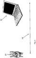
- Fig. 1 is a simplified schematic diagram illustrating an exemplary scenario to which the present embodiments can be applied.
- the hand 10 of a user is using finger gestures in order to interact with computer 12.
- Arrow 14 indicates a distance between the hand and the computer.
- the distance can be low in order to obtain high resolution but as the distance increases the resolution falls and at whatever distance, any feature in the object that subtends an angle that is smaller than the pixel size cannot be resolved.
- sub-pixel size features can be resolved.
- each of the camera sensor pixels defines a relatively large area in space therefore enabling the detection of the light features positions only at low spatial resolution. The resolution of the depth detection is degraded as well when using triangulation methods.
- the present embodiments address the issue, as will be explained below, by providing sub-pixel resolution of structured light features.
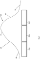
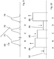
- Fig. 2 is a simplified schematic diagram illustrating what happens optically when a reflected and somewhat distorted light distribution arrives at a detector made up of multiple pixels.
- the reflected beam arrives at three detector pixels 20A, 20B and 20C as a brightness distribution 22, typically a Gaussian distribution, or slightly distorted Gaussian distribution, having a central peak 24, relatively steep regions of falloff 26 around the peak and then a relatively flat tail region 28 as the brightness tends towards zero.
- the peak region 24 is wider than or as wide as the pixel size, the corresponding shape can be resolved.
- the peak is narrower than the pixel size, then in the prior art the peak cannot be localized to greater resolution than the individual pixel.
- peak 24 coincides with the right hand side of detector pixel 20B.
- Fig. 3 is the same view as Fig. 2 a few moments later when the Gaussian distribution has moved in accordance with arrow 30 so that now peak 24 has crossed to the opposite side of pixel 20B, a change in situation which cannot be detected by the prior art systems since the peak is still within the same pixel.
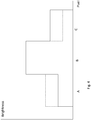
- Fig. 4 is a schematic graph illustrating the brightness at each pixel, A, B and C, and how it varies between the situations of Fig. 2 and Fig. 3 , thus allowing for the sub-pixel movement between Figs. 2 and 3 to be detected.
- Brightness levels indicated by continuous lines illustrate the situation of Fig. 2 .
- Dashed lines illustrate the changes brought about as the peak moves to the position of Fig. 3 .
- the present embodiments may typically use structured light.
- the light may be produced by laser through a projector or optical fibers or a scanner.
- the structure may involve spots or parallel lines or a grid or the like, or combinations of different structures may be used. For example a finer structure may be applied to an area of particular interest as opposed to the remainder of the scene.
- Fig. 4 Considering Fig. 4 and the first thing to be noted is that at Pixel B there is no change since the peak remains within the confines of Pixel B. However, in Fig. 2 , Pixel A coincides with a tail region 28, and Pixel C coincides with a slope region 26. In Fig. 3 the situation is reversed as the peak has moved away from pixel A towards pixel C. Thus pixel C coincides with a tail region 28 and pixel A with a slope region 26. Thus, as illustrated in Fig. 4 , as the peak moves towards pixel A, the brightness at pixel A increases. At the same time, the peak moves away from pixel C and the brightness at pixel C decreases.
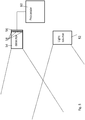
- Detector apparatus 50 comprises a light source 52 which shines structured light beams onto the volume.
- the light source is typically a laser source that uses semiconductor edge emitting lasers or VCSEL lasers.
- a digital detector 54 typically a camera, has a sensor 56 with detection pixels 58 of a particular size.
- the laser beams when shone into the volume and reflected back to the detection pixels 58, have a brightness distribution having a peak.
- the peak may be smaller than the pixel size.
- An alternative case is that of light saturation, in which case the peak is the entire saturated area, which may be an entire pixel or more, so the interest may be in the area around the peak in surrounding pixels.
- Electronic processor 60 assesses a distribution of brightness between neighbouring pixels to infer a location of the peak or underlying feature within a region smaller than the actual pixel size.
- the brightness distribution may be static or in some cases dynamic, as discussed above in respect of Fig. 4 .
- Fig. 5 structured light is used. Therefore a diffractive element is in both cases located in front of the laser. A collimator is also typically provided. The embodiment of Fig. 5 may have an additional diffractive element located in front of the camera sensor in order to manage light distribution around the neighbouring sensors.
- structured light may also be generated using a scanner, so that an initial diffractive element may not be needed in front of the light source.
- FIG. 6 is a simplified diagram illustrating a variation of the embodiment of Fig. 5 in which a diffraction element 62 is used.
- a pattern generator element 64 may be placed in front of laser source 52 to generate a structured light pattern of laser beams, and then diffraction element 62 splits each incoming beam at detector 54 into three beams, a central beam and two side beams. It will be appreciated that in a three-dimensional version the effect would be a central peak surrounded by a ring or any combination of a central peak surrounded by discrete or continues peaks.
- the diffraction element is arranged so that when the central peak falls on the center of a pixel, the side peaks fall on boundaries of the neighbouring peaks.
- the brightness distribution is shown in Fig. 7 .
- the pattern generator element 64 may be implemented by a suitable diffraction element, a laser scanner, or any other multiple lasers arrangement.
- a main beam 70 falls on a central pixel, C, of a set of five pixels A to E.
- Side beams 72 and 74 fall on the boundaries of pixels A and B, and D and E respectively.
- FIG. 8 shows the corresponding brightness levels registered by the pixels.
- Pixel C sees a brightness level 80 corresponding to a full beam distribution.
- Pixels A, B, D and E each see brightness levels 82, 84, 86 and 88, each equivalent to half a beam distribution.
- Figs. 9 and 10 illustrate the situation when the object causing the peaks moves slightly in the direction of arrow 90.
- the central peak 70 moves towards the boundary between pixels C and D.
- Side peak 72 moves towards the centre of pixel B, and side pixel 74 moves towards the center of pixel E.
- the brightness level 82 at pixel A drops almost to zero.
- the level 84 at pixel B rises almost to the maximum.
- the level 80 at pixel C falls somewhat.
- the level 86 at pixel D falls considerably, but not as much as pixel A since it reflects two tails.
- the brightness level 88 at pixel E rises almost to a maximum. Again the situation is dynamic and every position of the peak across pixel C will have a different signature of brightness levels across pixels A to E.
- each detection pixel is divided into multiple detection zones whose size is dictated by used combinations of the number of resolvable brightness levels.
- the processor 60 provides the mapping logic for mapping the different combinations of levels of brightness on the detection pixels A to E to one of the zones on the central one of the group of detection pixels involved.
- An embodiment may allow a resolution level of one tenth of the pixel size.
- the beam from the object moves across the detector, different pixels in turn serve as the central and neighbouring pixels.
- the neighboring pixels need not be adjacent to each other but may be any predefined pixels arrangement.
- the mapping logic may map in two or three dimensions.
- the figures show two dimensions for simplicity but the skilled person will appreciate that a three dimensional system is generally required in a practical situation.
- the element 62 may be a distortion element.
- the distortion element simply distorts the Gaussian distribution of the brightness into any predetermined shape that spreads over neighboring pixels and allows the passage of the peak over the central pixel to be resolved.
- the distortion may involve side peaks and thus work in a way that is similar to that of the diffraction element embodiment.
- the distortion may sharpen the central peak and redistribute the energy in the tail region.
- any other distortion giving information about the location of the peak based on brightness changes in the central and neighbouring pixels may be used.
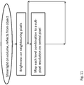
- Fig. 11 illustrates a method of sub-resolution optical detection of movement within a volume, for use with the apparatus described above.
- the method comprises shining light beams into the volume so that objects within the volume can cause reflection of the beams onto a detector.
- the detector has detection pixels as discussed.
- the beams when shone into the volume and reflected back to the detection pixels have a brightness distribution, such as a Gaussian distribution, which has a peak.
- the peak is smaller than the pixel size.
- the method involves electronically assessing a distribution of brightness between neighbouring pixels.
- the distribution is then used to infer, for example by mapping, a location of the peak within a region within a single, central detection pixel, which region is smaller than the pixel size.
- the object moves the brightness levels of the pixels change, and the motion of the peak within the central pixel of the group can be traced.
- the method may further involve applying diffraction to the beam as it arrives at the detector, so as to generate side peaks.
- the level of diffraction may be chosen so that the side peaks arrive at gaps between pixels when the main peak arrives at the center of a pixel, so as to maximize the effect of motion on the brightness levels over the group of pixels.
- the method includes dividing each pixel into discrete zones. Typically the number of zones is selected based on the resolvable number of brightness levels and combinations that can be detected. Image processing then serves to map each pattern of brightness levels at the pixels into a zone on the central pixel. The mapping may be in two or three dimensions.
- a typical resolution for the mapping is about one tenth of the pixel size, which may allow standard off-the shelf detectors to accurately detect finger motion at a distance of four or five meters.
- the beams may be collimated at the beam source.
- the method may comprise applying a distortion to the incoming brightness distribution to distort the incoming distribution over a central detection pixel and neighbouring pixels in a way that allows movement to be accurately measured.
Landscapes
- Engineering & Computer Science (AREA)
- Physics & Mathematics (AREA)
- Theoretical Computer Science (AREA)
- General Physics & Mathematics (AREA)
- General Engineering & Computer Science (AREA)
- Human Computer Interaction (AREA)
- Remote Sensing (AREA)
- Computer Networks & Wireless Communication (AREA)
- Radar, Positioning & Navigation (AREA)
- Electromagnetism (AREA)
- Computer Vision & Pattern Recognition (AREA)
- Optics & Photonics (AREA)
- Length Measuring Devices By Optical Means (AREA)
- Image Input (AREA)
- Image Processing (AREA)
Applications Claiming Priority (1)
| Application Number | Priority Date | Filing Date | Title |
|---|---|---|---|
| US201461926476P | 2014-01-13 | 2014-01-13 |
Publications (2)
| Publication Number | Publication Date |
|---|---|
| EP2894546A1 EP2894546A1 (en) | 2015-07-15 |
| EP2894546B1 true EP2894546B1 (en) | 2018-07-18 |
Family
ID=52345084
Family Applications (1)
| Application Number | Title | Priority Date | Filing Date |
|---|---|---|---|
| EP15150899.1A Active EP2894546B1 (en) | 2014-01-13 | 2015-01-13 | Sub-resolution optical detection |
Country Status (5)
| Country | Link |
|---|---|
| US (1) | US9523771B2 (enExample) |
| EP (1) | EP2894546B1 (enExample) |
| JP (1) | JP6359466B2 (enExample) |
| KR (1) | KR102046944B1 (enExample) |
| CN (1) | CN104776797B (enExample) |
Families Citing this family (15)
| Publication number | Priority date | Publication date | Assignee | Title |
|---|---|---|---|---|
| IE59105B1 (en) | 1985-05-06 | 1994-01-12 | Richardson Vicks Inc | Diagnostic method for detecting periodontal disease |
| JP5926184B2 (ja) * | 2009-09-22 | 2016-05-25 | ペブルステック リミテッド | コンピュータ装置の遠隔制御 |
| US11493998B2 (en) | 2012-01-17 | 2022-11-08 | Ultrahaptics IP Two Limited | Systems and methods for machine control |
| US8693731B2 (en) | 2012-01-17 | 2014-04-08 | Leap Motion, Inc. | Enhanced contrast for object detection and characterization by optical imaging |
| US12260023B2 (en) | 2012-01-17 | 2025-03-25 | Ultrahaptics IP Two Limited | Systems and methods for machine control |
| US9702977B2 (en) | 2013-03-15 | 2017-07-11 | Leap Motion, Inc. | Determining positional information of an object in space |
| US9552074B2 (en) | 2014-05-21 | 2017-01-24 | Facebook, Inc. | Method and system for generating user feedback of a gesture capturing device |
| KR101908057B1 (ko) | 2014-12-18 | 2018-10-15 | 페이스북, 인크. | 가상 현실 환경을 위한 사용자 인터페이스를 제공하기 위한 시스템, 장치 및 방법 |
| KR20170104506A (ko) * | 2015-01-06 | 2017-09-15 | 페이스북, 인크. | 패턴화 광을 사용하는 깊이 맵핑을 제공하기 위한 방법 및 시스템 |
| EP3057067B1 (en) * | 2015-02-16 | 2017-08-23 | Thomson Licensing | Device and method for estimating a glossy part of radiation |
| US10366674B1 (en) * | 2016-12-27 | 2019-07-30 | Facebook Technologies, Llc | Display calibration in electronic displays |
| DE112018000284B4 (de) * | 2017-01-24 | 2023-04-06 | Analog Devices, Inc. | Bereitstellen eines dynamischen Sichtfelds für von einer dynamischen Position empfangenes Licht |
| US10620316B2 (en) * | 2017-05-05 | 2020-04-14 | Qualcomm Incorporated | Systems and methods for generating a structured light depth map with a non-uniform codeword pattern |
| KR102693894B1 (ko) | 2019-03-29 | 2024-08-12 | 삼성전자주식회사 | 광각 고해상도 거리 측정 장치 |
| DE102020207302A1 (de) | 2020-06-10 | 2021-12-16 | Fraunhofer-Gesellschaft zur Förderung der angewandten Forschung eingetragener Verein | Vorrichtung und Verfahren zur Aufnahme eines projizierten Punktmusters in einer Anzeigevorrichtung |
Family Cites Families (18)
| Publication number | Priority date | Publication date | Assignee | Title |
|---|---|---|---|---|
| JP2755885B2 (ja) * | 1992-11-26 | 1998-05-25 | 株式会社クボタ | Ccdへの入射光線束の位置検出方法 |
| JP2851227B2 (ja) * | 1993-08-03 | 1999-01-27 | 株式会社クボタ | Ccdへの入射光線束の位置検出方法 |
| JP3212777B2 (ja) * | 1993-10-28 | 2001-09-25 | 三菱電機株式会社 | 画像処理装置 |
| US6407817B1 (en) * | 1993-12-20 | 2002-06-18 | Minolta Co., Ltd. | Measuring system with improved method of reading image data of an object |
| SE9700384D0 (sv) * | 1997-02-04 | 1997-02-04 | Biacore Ab | Analytical method and apparatus |
| JP3858994B2 (ja) * | 2002-11-28 | 2006-12-20 | 株式会社山武 | 位置検出方法および装置 |
| KR100622243B1 (ko) * | 2004-02-17 | 2006-09-14 | 오므론 가부시키가이샤 | 광학식 측정 장치 및 광학식 측정 방법 |
| WO2007105205A2 (en) * | 2006-03-14 | 2007-09-20 | Prime Sense Ltd. | Three-dimensional sensing using speckle patterns |
| US7534988B2 (en) | 2005-11-08 | 2009-05-19 | Microsoft Corporation | Method and system for optical tracking of a pointing object |
| US7885480B2 (en) * | 2006-10-31 | 2011-02-08 | Mitutoyo Corporation | Correlation peak finding method for image correlation displacement sensing |
| CN100580367C (zh) * | 2007-02-13 | 2010-01-13 | 宏濑科技股份有限公司 | 侦测待测物表面的轮廓的测量方法 |
| CN105185026B (zh) * | 2007-11-15 | 2018-09-11 | 爱克斯崔里斯科技有限公司 | 颗粒探测 |
| WO2009073649A1 (en) * | 2007-12-04 | 2009-06-11 | Particle Measuring Systems, Inc. | Non-orthogonal particle detection systems and methods |
| CN101451826B (zh) * | 2008-12-17 | 2010-06-09 | 中国科学院上海光学精密机械研究所 | 物体三维轮廓测量装置及测量方法 |
| JP2011163852A (ja) * | 2010-02-08 | 2011-08-25 | Kobe Steel Ltd | 外観検査装置 |
| CN101806723B (zh) * | 2010-04-02 | 2011-05-25 | 中国科学院上海光学精密机械研究所 | 双束多功能z扫描光学非线性测量装置和方法 |
| WO2013087450A2 (en) * | 2011-12-13 | 2013-06-20 | Sony Corporation | Estimation of global vertical shift for stereoscopic images |
| US9518864B2 (en) * | 2011-12-15 | 2016-12-13 | Facebook, Inc. | Controllable optical sensing |
-
2015
- 2015-01-13 CN CN201510015538.4A patent/CN104776797B/zh active Active
- 2015-01-13 EP EP15150899.1A patent/EP2894546B1/en active Active
- 2015-01-13 JP JP2015004519A patent/JP6359466B2/ja active Active
- 2015-01-13 US US14/595,369 patent/US9523771B2/en active Active
- 2015-01-13 KR KR1020150006449A patent/KR102046944B1/ko not_active Expired - Fee Related
Non-Patent Citations (1)
| Title |
|---|
| None * |
Also Published As
| Publication number | Publication date |
|---|---|
| CN104776797A (zh) | 2015-07-15 |
| KR102046944B1 (ko) | 2019-11-20 |
| US20150198716A1 (en) | 2015-07-16 |
| US9523771B2 (en) | 2016-12-20 |
| CN104776797B (zh) | 2018-01-02 |
| JP6359466B2 (ja) | 2018-07-18 |
| JP2015143685A (ja) | 2015-08-06 |
| KR20150084680A (ko) | 2015-07-22 |
| EP2894546A1 (en) | 2015-07-15 |
Similar Documents
| Publication | Publication Date | Title |
|---|---|---|
| EP2894546B1 (en) | Sub-resolution optical detection | |
| JP5138119B2 (ja) | 物体検出装置および情報取得装置 | |
| EP2336715B1 (en) | Method for positioning by using optical speckle | |
| CN105960569B (zh) | 使用二维图像处理来检查三维物体的方法 | |
| JP6046929B2 (ja) | 光学測定装置 | |
| CN102749039B (zh) | 形状测量设备 | |
| KR101925028B1 (ko) | 깊이 영상 생성 장치 및 방법 | |
| JP5500462B2 (ja) | 形状測定装置、観察装置および画像処理方法 | |
| JP7117189B2 (ja) | 光学式変位計 | |
| JP6112909B2 (ja) | シャック・ハルトマンセンサーを用いた形状計測装置、形状計測方法 | |
| EP3441812B1 (en) | Pattern based autofocus method for a microscopy | |
| US20090207419A1 (en) | Large areas undistorted imaging apparatus for light speckles and method thereof | |
| EP2410366A1 (en) | Focus information generating device and focus information generating method | |
| US20160356596A1 (en) | Apparatus for measuring shape of object, and methods, system, and storage medium storing program related thereto | |
| JP6491833B2 (ja) | 高さ測定装置 | |
| JP6542906B2 (ja) | 少なくとも部分的に透明な物体の表面に関連する表面データおよび/または測定データを決定するための方法および装置 | |
| US20160349496A1 (en) | Control apparatus and control method for spatial light modulator | |
| US12439024B2 (en) | Provision of real world and image sensor correspondence points for use in calibration of an imaging system for three dimensional imaging based on light triangulation | |
| JP6179366B2 (ja) | 標準ゲージ、三次元測定装置、及び、三次元測定装置のキャリブレーション方法 | |
| KR20130040029A (ko) | 측정 대상 물체에 대한 거리를 측정하는 방법 및 장치 | |
| JP2015099048A (ja) | 標準ゲージ、三次元測定装置、及び、三次元測定装置のキャリブレーション方法 | |
| JP4496149B2 (ja) | 寸法測定装置 | |
| EP4488940A1 (en) | Method for 3d reconstruction | |
| JP2014211305A (ja) | 物体検出装置および情報取得装置 | |
| CN109211106A (zh) | 光学测量设备 |
Legal Events
| Date | Code | Title | Description |
|---|---|---|---|
| PUAI | Public reference made under article 153(3) epc to a published international application that has entered the european phase |
Free format text: ORIGINAL CODE: 0009012 |
|
| 17P | Request for examination filed |
Effective date: 20150113 |
|
| AK | Designated contracting states |
Kind code of ref document: A1 Designated state(s): AL AT BE BG CH CY CZ DE DK EE ES FI FR GB GR HR HU IE IS IT LI LT LU LV MC MK MT NL NO PL PT RO RS SE SI SK SM TR |
|
| AX | Request for extension of the european patent |
Extension state: BA ME |
|
| RAP1 | Party data changed (applicant data changed or rights of an application transferred) |
Owner name: OCULUS VR, LLC |
|
| STAA | Information on the status of an ep patent application or granted ep patent |
Free format text: STATUS: EXAMINATION IS IN PROGRESS |
|
| 17Q | First examination report despatched |
Effective date: 20170124 |
|
| RAP1 | Party data changed (applicant data changed or rights of an application transferred) |
Owner name: FACEBOOK INC. |
|
| GRAP | Despatch of communication of intention to grant a patent |
Free format text: ORIGINAL CODE: EPIDOSNIGR1 |
|
| STAA | Information on the status of an ep patent application or granted ep patent |
Free format text: STATUS: GRANT OF PATENT IS INTENDED |
|
| RIC1 | Information provided on ipc code assigned before grant |
Ipc: G06T 7/521 20170101ALI20180207BHEP Ipc: G01S 17/48 20060101ALN20180207BHEP Ipc: G06T 7/00 20170101ALN20180207BHEP Ipc: G06F 3/01 20060101AFI20180207BHEP Ipc: G06F 3/03 20060101ALI20180207BHEP Ipc: G01S 17/89 20060101ALN20180207BHEP Ipc: G01S 17/06 20060101ALI20180207BHEP Ipc: G01B 11/25 20060101ALI20180207BHEP Ipc: G01S 7/481 20060101ALN20180207BHEP |
|
| INTG | Intention to grant announced |
Effective date: 20180306 |
|
| GRAS | Grant fee paid |
Free format text: ORIGINAL CODE: EPIDOSNIGR3 |
|
| GRAJ | Information related to disapproval of communication of intention to grant by the applicant or resumption of examination proceedings by the epo deleted |
Free format text: ORIGINAL CODE: EPIDOSDIGR1 |
|
| GRAL | Information related to payment of fee for publishing/printing deleted |
Free format text: ORIGINAL CODE: EPIDOSDIGR3 |
|
| STAA | Information on the status of an ep patent application or granted ep patent |
Free format text: STATUS: EXAMINATION IS IN PROGRESS |
|
| GRAR | Information related to intention to grant a patent recorded |
Free format text: ORIGINAL CODE: EPIDOSNIGR71 |
|
| STAA | Information on the status of an ep patent application or granted ep patent |
Free format text: STATUS: GRANT OF PATENT IS INTENDED |
|
| GRAA | (expected) grant |
Free format text: ORIGINAL CODE: 0009210 |
|
| STAA | Information on the status of an ep patent application or granted ep patent |
Free format text: STATUS: THE PATENT HAS BEEN GRANTED |
|
| INTC | Intention to grant announced (deleted) | ||
| RIC1 | Information provided on ipc code assigned before grant |
Ipc: G06F 3/03 20060101ALI20180529BHEP Ipc: G01S 7/481 20060101ALN20180529BHEP Ipc: G01B 11/25 20060101ALI20180529BHEP Ipc: G01S 17/48 20060101ALN20180529BHEP Ipc: G06F 3/01 20060101AFI20180529BHEP Ipc: G06T 7/521 20170101ALI20180529BHEP Ipc: G01S 17/89 20060101ALN20180529BHEP Ipc: G01S 17/06 20060101ALI20180529BHEP Ipc: G06T 7/00 20170101ALN20180529BHEP |
|
| INTG | Intention to grant announced |
Effective date: 20180607 |
|
| AK | Designated contracting states |
Kind code of ref document: B1 Designated state(s): AL AT BE BG CH CY CZ DE DK EE ES FI FR GB GR HR HU IE IS IT LI LT LU LV MC MK MT NL NO PL PT RO RS SE SI SK SM TR |
|
| REG | Reference to a national code |
Ref country code: GB Ref legal event code: FG4D |
|
| REG | Reference to a national code |
Ref country code: CH Ref legal event code: EP |
|
| REG | Reference to a national code |
Ref country code: IE Ref legal event code: FG4D |
|
| REG | Reference to a national code |
Ref country code: AT Ref legal event code: REF Ref document number: 1020029 Country of ref document: AT Kind code of ref document: T Effective date: 20180815 |
|
| REG | Reference to a national code |
Ref country code: DE Ref legal event code: R096 Ref document number: 602015013576 Country of ref document: DE |
|
| REG | Reference to a national code |
Ref country code: NL Ref legal event code: MP Effective date: 20180718 |
|
| REG | Reference to a national code |
Ref country code: LT Ref legal event code: MG4D |
|
| REG | Reference to a national code |
Ref country code: AT Ref legal event code: MK05 Ref document number: 1020029 Country of ref document: AT Kind code of ref document: T Effective date: 20180718 |
|
| PG25 | Lapsed in a contracting state [announced via postgrant information from national office to epo] |
Ref country code: NL Free format text: LAPSE BECAUSE OF FAILURE TO SUBMIT A TRANSLATION OF THE DESCRIPTION OR TO PAY THE FEE WITHIN THE PRESCRIBED TIME-LIMIT Effective date: 20180718 |
|
| PG25 | Lapsed in a contracting state [announced via postgrant information from national office to epo] |
Ref country code: PL Free format text: LAPSE BECAUSE OF FAILURE TO SUBMIT A TRANSLATION OF THE DESCRIPTION OR TO PAY THE FEE WITHIN THE PRESCRIBED TIME-LIMIT Effective date: 20180718 Ref country code: LT Free format text: LAPSE BECAUSE OF FAILURE TO SUBMIT A TRANSLATION OF THE DESCRIPTION OR TO PAY THE FEE WITHIN THE PRESCRIBED TIME-LIMIT Effective date: 20180718 Ref country code: IS Free format text: LAPSE BECAUSE OF FAILURE TO SUBMIT A TRANSLATION OF THE DESCRIPTION OR TO PAY THE FEE WITHIN THE PRESCRIBED TIME-LIMIT Effective date: 20181118 Ref country code: RS Free format text: LAPSE BECAUSE OF FAILURE TO SUBMIT A TRANSLATION OF THE DESCRIPTION OR TO PAY THE FEE WITHIN THE PRESCRIBED TIME-LIMIT Effective date: 20180718 Ref country code: AT Free format text: LAPSE BECAUSE OF FAILURE TO SUBMIT A TRANSLATION OF THE DESCRIPTION OR TO PAY THE FEE WITHIN THE PRESCRIBED TIME-LIMIT Effective date: 20180718 Ref country code: NO Free format text: LAPSE BECAUSE OF FAILURE TO SUBMIT A TRANSLATION OF THE DESCRIPTION OR TO PAY THE FEE WITHIN THE PRESCRIBED TIME-LIMIT Effective date: 20181018 Ref country code: GR Free format text: LAPSE BECAUSE OF FAILURE TO SUBMIT A TRANSLATION OF THE DESCRIPTION OR TO PAY THE FEE WITHIN THE PRESCRIBED TIME-LIMIT Effective date: 20181019 Ref country code: SE Free format text: LAPSE BECAUSE OF FAILURE TO SUBMIT A TRANSLATION OF THE DESCRIPTION OR TO PAY THE FEE WITHIN THE PRESCRIBED TIME-LIMIT Effective date: 20180718 Ref country code: FI Free format text: LAPSE BECAUSE OF FAILURE TO SUBMIT A TRANSLATION OF THE DESCRIPTION OR TO PAY THE FEE WITHIN THE PRESCRIBED TIME-LIMIT Effective date: 20180718 Ref country code: BG Free format text: LAPSE BECAUSE OF FAILURE TO SUBMIT A TRANSLATION OF THE DESCRIPTION OR TO PAY THE FEE WITHIN THE PRESCRIBED TIME-LIMIT Effective date: 20181018 |
|
| PG25 | Lapsed in a contracting state [announced via postgrant information from national office to epo] |
Ref country code: HR Free format text: LAPSE BECAUSE OF FAILURE TO SUBMIT A TRANSLATION OF THE DESCRIPTION OR TO PAY THE FEE WITHIN THE PRESCRIBED TIME-LIMIT Effective date: 20180718 Ref country code: AL Free format text: LAPSE BECAUSE OF FAILURE TO SUBMIT A TRANSLATION OF THE DESCRIPTION OR TO PAY THE FEE WITHIN THE PRESCRIBED TIME-LIMIT Effective date: 20180718 Ref country code: LV Free format text: LAPSE BECAUSE OF FAILURE TO SUBMIT A TRANSLATION OF THE DESCRIPTION OR TO PAY THE FEE WITHIN THE PRESCRIBED TIME-LIMIT Effective date: 20180718 |
|
| REG | Reference to a national code |
Ref country code: DE Ref legal event code: R081 Ref document number: 602015013576 Country of ref document: DE Owner name: META PLATFORMS TECHNOLOGIES, LLC, MENLO PARK, US Free format text: FORMER OWNER: FACEBOOK, INC., MENLO PARK, CALIF., US Ref country code: DE Ref legal event code: R082 Ref document number: 602015013576 Country of ref document: DE Representative=s name: MEISSNER BOLTE PATENTANWAELTE RECHTSANWAELTE P, DE Ref country code: DE Ref legal event code: R081 Ref document number: 602015013576 Country of ref document: DE Owner name: FACEBOOK TECHNOLOGIES, LLC, MENLO PARK, US Free format text: FORMER OWNER: FACEBOOK, INC., MENLO PARK, CALIF., US Ref country code: DE Ref legal event code: R082 Ref document number: 602015013576 Country of ref document: DE Representative=s name: MURGITROYD & COMPANY, DE |
|
| REG | Reference to a national code |
Ref country code: DE Ref legal event code: R097 Ref document number: 602015013576 Country of ref document: DE |
|
| PG25 | Lapsed in a contracting state [announced via postgrant information from national office to epo] |
Ref country code: CZ Free format text: LAPSE BECAUSE OF FAILURE TO SUBMIT A TRANSLATION OF THE DESCRIPTION OR TO PAY THE FEE WITHIN THE PRESCRIBED TIME-LIMIT Effective date: 20180718 Ref country code: RO Free format text: LAPSE BECAUSE OF FAILURE TO SUBMIT A TRANSLATION OF THE DESCRIPTION OR TO PAY THE FEE WITHIN THE PRESCRIBED TIME-LIMIT Effective date: 20180718 Ref country code: IT Free format text: LAPSE BECAUSE OF FAILURE TO SUBMIT A TRANSLATION OF THE DESCRIPTION OR TO PAY THE FEE WITHIN THE PRESCRIBED TIME-LIMIT Effective date: 20180718 Ref country code: ES Free format text: LAPSE BECAUSE OF FAILURE TO SUBMIT A TRANSLATION OF THE DESCRIPTION OR TO PAY THE FEE WITHIN THE PRESCRIBED TIME-LIMIT Effective date: 20180718 Ref country code: EE Free format text: LAPSE BECAUSE OF FAILURE TO SUBMIT A TRANSLATION OF THE DESCRIPTION OR TO PAY THE FEE WITHIN THE PRESCRIBED TIME-LIMIT Effective date: 20180718 |
|
| PLBE | No opposition filed within time limit |
Free format text: ORIGINAL CODE: 0009261 |
|
| STAA | Information on the status of an ep patent application or granted ep patent |
Free format text: STATUS: NO OPPOSITION FILED WITHIN TIME LIMIT |
|
| REG | Reference to a national code |
Ref country code: DE Ref legal event code: R082 Ref document number: 602015013576 Country of ref document: DE Representative=s name: MURGITROYD GERMANY PATENTANWALTSGESELLSCHAFT M, DE Ref country code: DE Ref legal event code: R082 Ref document number: 602015013576 Country of ref document: DE Representative=s name: MURGITROYD & COMPANY, DE |
|
| PG25 | Lapsed in a contracting state [announced via postgrant information from national office to epo] |
Ref country code: DK Free format text: LAPSE BECAUSE OF FAILURE TO SUBMIT A TRANSLATION OF THE DESCRIPTION OR TO PAY THE FEE WITHIN THE PRESCRIBED TIME-LIMIT Effective date: 20180718 Ref country code: SK Free format text: LAPSE BECAUSE OF FAILURE TO SUBMIT A TRANSLATION OF THE DESCRIPTION OR TO PAY THE FEE WITHIN THE PRESCRIBED TIME-LIMIT Effective date: 20180718 Ref country code: SM Free format text: LAPSE BECAUSE OF FAILURE TO SUBMIT A TRANSLATION OF THE DESCRIPTION OR TO PAY THE FEE WITHIN THE PRESCRIBED TIME-LIMIT Effective date: 20180718 |
|
| REG | Reference to a national code |
Ref country code: DE Ref legal event code: R082 Ref document number: 602015013576 Country of ref document: DE Representative=s name: MURGITROYD & COMPANY, DE |
|
| 26N | No opposition filed |
Effective date: 20190423 |
|
| REG | Reference to a national code |
Ref country code: GB Ref legal event code: 732E Free format text: REGISTERED BETWEEN 20190627 AND 20190703 |
|
| PG25 | Lapsed in a contracting state [announced via postgrant information from national office to epo] |
Ref country code: SI Free format text: LAPSE BECAUSE OF FAILURE TO SUBMIT A TRANSLATION OF THE DESCRIPTION OR TO PAY THE FEE WITHIN THE PRESCRIBED TIME-LIMIT Effective date: 20180718 Ref country code: MC Free format text: LAPSE BECAUSE OF FAILURE TO SUBMIT A TRANSLATION OF THE DESCRIPTION OR TO PAY THE FEE WITHIN THE PRESCRIBED TIME-LIMIT Effective date: 20180718 |
|
| REG | Reference to a national code |
Ref country code: CH Ref legal event code: PL |
|
| PG25 | Lapsed in a contracting state [announced via postgrant information from national office to epo] |
Ref country code: LU Free format text: LAPSE BECAUSE OF NON-PAYMENT OF DUE FEES Effective date: 20190113 |
|
| REG | Reference to a national code |
Ref country code: BE Ref legal event code: MM Effective date: 20190131 |
|
| REG | Reference to a national code |
Ref country code: IE Ref legal event code: MM4A |
|
| PG25 | Lapsed in a contracting state [announced via postgrant information from national office to epo] |
Ref country code: BE Free format text: LAPSE BECAUSE OF NON-PAYMENT OF DUE FEES Effective date: 20190131 |
|
| PG25 | Lapsed in a contracting state [announced via postgrant information from national office to epo] |
Ref country code: CH Free format text: LAPSE BECAUSE OF NON-PAYMENT OF DUE FEES Effective date: 20190131 Ref country code: LI Free format text: LAPSE BECAUSE OF NON-PAYMENT OF DUE FEES Effective date: 20190131 |
|
| PG25 | Lapsed in a contracting state [announced via postgrant information from national office to epo] |
Ref country code: IE Free format text: LAPSE BECAUSE OF NON-PAYMENT OF DUE FEES Effective date: 20190113 |
|
| PG25 | Lapsed in a contracting state [announced via postgrant information from national office to epo] |
Ref country code: TR Free format text: LAPSE BECAUSE OF FAILURE TO SUBMIT A TRANSLATION OF THE DESCRIPTION OR TO PAY THE FEE WITHIN THE PRESCRIBED TIME-LIMIT Effective date: 20180718 |
|
| PG25 | Lapsed in a contracting state [announced via postgrant information from national office to epo] |
Ref country code: PT Free format text: LAPSE BECAUSE OF FAILURE TO SUBMIT A TRANSLATION OF THE DESCRIPTION OR TO PAY THE FEE WITHIN THE PRESCRIBED TIME-LIMIT Effective date: 20181118 Ref country code: MT Free format text: LAPSE BECAUSE OF NON-PAYMENT OF DUE FEES Effective date: 20190113 |
|
| PG25 | Lapsed in a contracting state [announced via postgrant information from national office to epo] |
Ref country code: CY Free format text: LAPSE BECAUSE OF FAILURE TO SUBMIT A TRANSLATION OF THE DESCRIPTION OR TO PAY THE FEE WITHIN THE PRESCRIBED TIME-LIMIT Effective date: 20180718 |
|
| PG25 | Lapsed in a contracting state [announced via postgrant information from national office to epo] |
Ref country code: HU Free format text: LAPSE BECAUSE OF FAILURE TO SUBMIT A TRANSLATION OF THE DESCRIPTION OR TO PAY THE FEE WITHIN THE PRESCRIBED TIME-LIMIT; INVALID AB INITIO Effective date: 20150113 |
|
| PG25 | Lapsed in a contracting state [announced via postgrant information from national office to epo] |
Ref country code: MK Free format text: LAPSE BECAUSE OF FAILURE TO SUBMIT A TRANSLATION OF THE DESCRIPTION OR TO PAY THE FEE WITHIN THE PRESCRIBED TIME-LIMIT Effective date: 20180718 |
|
| P01 | Opt-out of the competence of the unified patent court (upc) registered |
Effective date: 20230524 |
|
| REG | Reference to a national code |
Ref country code: DE Ref legal event code: R081 Ref document number: 602015013576 Country of ref document: DE Owner name: META PLATFORMS TECHNOLOGIES, LLC, MENLO PARK, US Free format text: FORMER OWNER: FACEBOOK TECHNOLOGIES, LLC, MENLO PARK, CALIF., US |
|
| PGFP | Annual fee paid to national office [announced via postgrant information from national office to epo] |
Ref country code: DE Payment date: 20250127 Year of fee payment: 11 |
|
| PGFP | Annual fee paid to national office [announced via postgrant information from national office to epo] |
Ref country code: FR Payment date: 20250131 Year of fee payment: 11 |
|
| PGFP | Annual fee paid to national office [announced via postgrant information from national office to epo] |
Ref country code: GB Payment date: 20250130 Year of fee payment: 11 |