EP2894014B1 - Lame, en particulier lame oscillante, destinée à être utilisée dans un processus de découpe mécanique, pour la découpe de plaques de sandwich - Google Patents
Lame, en particulier lame oscillante, destinée à être utilisée dans un processus de découpe mécanique, pour la découpe de plaques de sandwich Download PDFInfo
- Publication number
- EP2894014B1 EP2894014B1 EP14150776.4A EP14150776A EP2894014B1 EP 2894014 B1 EP2894014 B1 EP 2894014B1 EP 14150776 A EP14150776 A EP 14150776A EP 2894014 B1 EP2894014 B1 EP 2894014B1
- Authority
- EP
- European Patent Office
- Prior art keywords
- cutting
- cutting machine
- blade
- edge
- stroke
- Prior art date
- Legal status (The legal status is an assumption and is not a legal conclusion. Google has not performed a legal analysis and makes no representation as to the accuracy of the status listed.)
- Active
Links
- 238000005520 cutting process Methods 0.000 title claims description 240
- 238000000034 method Methods 0.000 title description 5
- 239000002131 composite material Substances 0.000 claims description 52
- 239000000463 material Substances 0.000 claims description 20
- 239000006260 foam Substances 0.000 claims description 5
- 239000011087 paperboard Substances 0.000 claims 2
- 230000035515 penetration Effects 0.000 claims 1
- 241000985128 Cladium mariscus Species 0.000 description 6
- 239000010410 layer Substances 0.000 description 5
- 239000013598 vector Substances 0.000 description 3
- 238000007654 immersion Methods 0.000 description 2
- 239000011229 interlayer Substances 0.000 description 2
- 238000003754 machining Methods 0.000 description 2
- 238000000465 moulding Methods 0.000 description 2
- 238000013459 approach Methods 0.000 description 1
- 230000001419 dependent effect Effects 0.000 description 1
- 238000009826 distribution Methods 0.000 description 1
- 238000004049 embossing Methods 0.000 description 1
- 238000003780 insertion Methods 0.000 description 1
- 230000037431 insertion Effects 0.000 description 1
- 235000021184 main course Nutrition 0.000 description 1
- 230000010355 oscillation Effects 0.000 description 1
- 238000006748 scratching Methods 0.000 description 1
- 230000002393 scratching effect Effects 0.000 description 1
- 239000000725 suspension Substances 0.000 description 1
Images


Classifications
-
- B—PERFORMING OPERATIONS; TRANSPORTING
- B26—HAND CUTTING TOOLS; CUTTING; SEVERING
- B26D—CUTTING; DETAILS COMMON TO MACHINES FOR PERFORATING, PUNCHING, CUTTING-OUT, STAMPING-OUT OR SEVERING
- B26D1/00—Cutting through work characterised by the nature or movement of the cutting member or particular materials not otherwise provided for; Apparatus or machines therefor; Cutting members therefor
- B26D1/0006—Cutting members therefor
-
- B—PERFORMING OPERATIONS; TRANSPORTING
- B26—HAND CUTTING TOOLS; CUTTING; SEVERING
- B26D—CUTTING; DETAILS COMMON TO MACHINES FOR PERFORATING, PUNCHING, CUTTING-OUT, STAMPING-OUT OR SEVERING
- B26D1/00—Cutting through work characterised by the nature or movement of the cutting member or particular materials not otherwise provided for; Apparatus or machines therefor; Cutting members therefor
- B26D1/01—Cutting through work characterised by the nature or movement of the cutting member or particular materials not otherwise provided for; Apparatus or machines therefor; Cutting members therefor involving a cutting member which does not travel with the work
- B26D1/04—Cutting through work characterised by the nature or movement of the cutting member or particular materials not otherwise provided for; Apparatus or machines therefor; Cutting members therefor involving a cutting member which does not travel with the work having a linearly-movable cutting member
- B26D1/06—Cutting through work characterised by the nature or movement of the cutting member or particular materials not otherwise provided for; Apparatus or machines therefor; Cutting members therefor involving a cutting member which does not travel with the work having a linearly-movable cutting member wherein the cutting member reciprocates
-
- B—PERFORMING OPERATIONS; TRANSPORTING
- B26—HAND CUTTING TOOLS; CUTTING; SEVERING
- B26D—CUTTING; DETAILS COMMON TO MACHINES FOR PERFORATING, PUNCHING, CUTTING-OUT, STAMPING-OUT OR SEVERING
- B26D1/00—Cutting through work characterised by the nature or movement of the cutting member or particular materials not otherwise provided for; Apparatus or machines therefor; Cutting members therefor
- B26D1/56—Cutting through work characterised by the nature or movement of the cutting member or particular materials not otherwise provided for; Apparatus or machines therefor; Cutting members therefor involving a cutting member which travels with the work otherwise than in the direction of the cut, i.e. flying cutter
- B26D1/58—Cutting through work characterised by the nature or movement of the cutting member or particular materials not otherwise provided for; Apparatus or machines therefor; Cutting members therefor involving a cutting member which travels with the work otherwise than in the direction of the cut, i.e. flying cutter and is mounted on a movable arm or the like
- B26D1/585—Cutting through work characterised by the nature or movement of the cutting member or particular materials not otherwise provided for; Apparatus or machines therefor; Cutting members therefor involving a cutting member which travels with the work otherwise than in the direction of the cut, i.e. flying cutter and is mounted on a movable arm or the like for thin material, e.g. for sheets, strips or the like
-
- B—PERFORMING OPERATIONS; TRANSPORTING
- B26—HAND CUTTING TOOLS; CUTTING; SEVERING
- B26D—CUTTING; DETAILS COMMON TO MACHINES FOR PERFORATING, PUNCHING, CUTTING-OUT, STAMPING-OUT OR SEVERING
- B26D1/00—Cutting through work characterised by the nature or movement of the cutting member or particular materials not otherwise provided for; Apparatus or machines therefor; Cutting members therefor
- B26D1/0006—Cutting members therefor
- B26D2001/0053—Cutting members therefor having a special cutting edge section or blade section
-
- B—PERFORMING OPERATIONS; TRANSPORTING
- B26—HAND CUTTING TOOLS; CUTTING; SEVERING
- B26D—CUTTING; DETAILS COMMON TO MACHINES FOR PERFORATING, PUNCHING, CUTTING-OUT, STAMPING-OUT OR SEVERING
- B26D1/00—Cutting through work characterised by the nature or movement of the cutting member or particular materials not otherwise provided for; Apparatus or machines therefor; Cutting members therefor
- B26D1/0006—Cutting members therefor
- B26D2001/006—Cutting members therefor the cutting blade having a special shape, e.g. a special outline, serrations
-
- Y—GENERAL TAGGING OF NEW TECHNOLOGICAL DEVELOPMENTS; GENERAL TAGGING OF CROSS-SECTIONAL TECHNOLOGIES SPANNING OVER SEVERAL SECTIONS OF THE IPC; TECHNICAL SUBJECTS COVERED BY FORMER USPC CROSS-REFERENCE ART COLLECTIONS [XRACs] AND DIGESTS
- Y10—TECHNICAL SUBJECTS COVERED BY FORMER USPC
- Y10T—TECHNICAL SUBJECTS COVERED BY FORMER US CLASSIFICATION
- Y10T83/00—Cutting
- Y10T83/465—Cutting motion of tool has component in direction of moving work
- Y10T83/4749—Tool mounted on oscillating standard
-
- Y—GENERAL TAGGING OF NEW TECHNOLOGICAL DEVELOPMENTS; GENERAL TAGGING OF CROSS-SECTIONAL TECHNOLOGIES SPANNING OVER SEVERAL SECTIONS OF THE IPC; TECHNICAL SUBJECTS COVERED BY FORMER USPC CROSS-REFERENCE ART COLLECTIONS [XRACs] AND DIGESTS
- Y10—TECHNICAL SUBJECTS COVERED BY FORMER USPC
- Y10T—TECHNICAL SUBJECTS COVERED BY FORMER US CLASSIFICATION
- Y10T83/00—Cutting
- Y10T83/929—Tool or tool with support
- Y10T83/9454—Reciprocable type
Definitions
- the invention relates to a knife, in particular oscillating knife, for use in a particular oscillating cutting tool of a cutting machine according to the preamble of the independent claim 1.
- Maschinueller Oszillierschneidebacter and cutting machines with, for example, oscillating - that is driven - cutting tool and suitable for this oscillating, so that especially the cutting of a multi-wall composite panel - in particular sandwich panel - is provided, are known in the art.
- a multi-wall composite panel is understood to be a sandwich panel, in particular of cardboard or cardboard material or plastic, which is constructed from at least one upper and one spaced apart lower comparatively strong, heavy-walled wall and has a comparatively light-weighted intermediate layer therebetween, in particular in the form of an intermediate wall five and 60 mm high intermediate structure, the example from thin-walled cardboard or cardboard material - such as honeycomb structure - or lightweight plastic - such as foam - exists.
- the cutting machine and a correspondingly designed cutting tool for this purpose can provide a stroke stitching mode in which the plates can be cut or cut to size as desired.
- a knife inserted into a knife holder of the cutting tool by the cutting tool and the cutting machine in a stroke direction oscillating lowering and lifting substantially perpendicular to the composite sheet to be cut moves and guided in a feed direction along the composite plate.
- the stroke stitch mode may include a stroke of between about 0.2 and about 12 millimeters, a stroke frequency of between about 50 and about 800 Hz (with a sinusoidal linear sweep), and a feed rate of between about 0.1 and about 4 meters per inch Second.
- the oscillating movement of the knife reduces the pushing force in the direction of travel (also called the feed direction).
- the field of application for pointed knives is aimed in particular at the machining of fine radii and small parts.
- the feed rate should generally be reduced compared to the use of flat knives in order to achieve a sufficient cutting result.
- the subject invention relates to a cutting machine blade for use in a cutting tool of a cutting machine, designed and precisely provided for cutting a multi-wall composite panel - in particular sandwich panel - of cardboard or cardboard material or plastic, the at least one upper and a lower spaced respectively comparatively strong sheared wall and an intervening comparatively light interlayer, in particular in the form of a structure of between five and 60 millimeters high of material with cavities, in particular designed as a repeating cell pattern structure or foam.
- the cutting machine knife is intended for use in an automatic cutting mode in which the cutting machine knife is guided by the cutting machine in a feed direction along the composite board.
- the cutting blade is designed as a flat knife and provided for use in a cutting mode in which at relatively high speeds (feed speeds) large radii or straight lines or large parts are cut from composite panels.
- the cutting machine blade has a holding section for use of the cutting machine blade in a knife holder of the cutting tool and a blade with cutting edge.
- the cutting edge in the region of the intermediate zone may advantageously in particular in such a way - relative to the feed direction - extends obliquely behind, that the curves of the cutting edge within the first and the second zone - respectively orthogonally projected on the feed direction - overlap at least partially, in particular substantially completely overlap, in particular so that the progressions of the cutting edge within the first and second zones are substantially offset in parallel only in the direction orthogonal to the feed direction.
- the first zone of the cutting edge in the context of this invention is formed by that portion of the cutting edge, which is intended and made just to cut in a defined and then for this knife exactly intended cutting mode, the bottom wall of the composite plate.
- the second zone of the cutting edge in the context of this invention is formed by that portion of the cutting edge, which is intended and made just to cut in a defined and then for this knife exactly intended cutting mode, the upper wall of the composite plate.
- angles are to be understood that form a respective main course direction of the respective profiles in the respective zones with the feed direction (respectively smaller of the two angles formed between the vectors, considered when the respective vector suspension points of the two vectors are superposed). If a profile in a zone does not run straight, then a main profile of the profile is to be considered or a direction in which the profile in the corresponding zone extends substantially in the middle (thereby away from the blade tip corner in the direction of the knife neck).
- the course direction of a profile within a respective zone is therefore considered to be in the same direction as the cutting edge extends away from its origin in the blade tip (ie away from the blade tip in the direction of the blade neck or holding region of the blade which the blade point corner (bottom point) is not on the
- the back of the blade is located and between the blade tip and blade back a "reverting" tip section is formed - possibly also away from the blade tip corner in the direction of the back]).
- the intermediate region is now aligned suboptimally with respect to its cutting angle to the intermediate structure of the composite panel, which is likewise to be cut through.
- this drawback overall does not significantly affect the cutting result, since the intermediate structure consists of precisely cut material (in particular with cavities) and thus can be cut sufficiently well even with a suboptimal cutting angle.
- the invention may in particular be an oscillating blade for use in an oscillating cutting tool.
- the Oszilliermesser should then be designed so that it is specially designed and predestined for use in a defined Hubstichmodus in which the knife - in addition to the guide along the feed direction - by the cutting tool in a stroke direction oscillating up and down substantially perpendicular to cutting composite plate is moved.
- the stroke movement itself can be carried out in particular linearly sinusoidal, so that combined from the two movements results in a sinusoidal curve as a combined path of movement.
- the stroke stitch mode for which the knife is made may have a stroke of between about 0.2 and about 12 millimeters, a stroke frequency of between about 50 and about 800 Hz, and a feed rate of between about 0.1 and about 4 meters per inch Second.
- the oscillating cutting offers, for example, the advantage of cutting, which is carried out using a non-self-driven cutting tool with inserted pulling knife - for example, the advantages that the main cutting direction is substantially vertical instead of horizontal and thus the horizontal cutting forces are reduced (so that Technique is typically used for composite panels with comparatively thick, firm upper and lower walls).
- a knife which is specially designed and provided for cutting a multi-sandwich plate can also be designed such that the teaching of the invention has a plurality of wall cutting zones and a respective plurality of "receding" intermediate zones such that one adjoins an intermediate zone upwards Wall cutting zone (in comparison to downwardly adjoining wall cutting zone) by the course of the cutting edge within the intermediate zone to the rear (viewed in the feed direction) is added, in the sense of the teaching of the invention described above.
- the invention also relates to a cutting machine with cutting tool having a knife holder, in which a cutting machine blade according to the invention - as described above - is used.
- the cutting machine thereby provides a cutting mode in which the cutting machine blade is guided by the cutting machine in a feed direction along the composite plate.
- the cutting machine with the cutting machine blade used is then precisely designed and provided for cutting a multi-wall composite panel - in particular sandwich panel - of cardboard or cardboard material or plastic, which has at least one upper and a lower spaced comparatively strong heavy wall and at least one between them lying comparatively light interlayer, especially in the form of one between five and 60 millimeter high structure of material with cavities, specifically designed as a repeating cell pattern structure or foam.
- the invention relates to the use of the cutting machine blade according to the invention - as described above - used in a cutting machine with cutting tool and also a method for cutting composite panels of the aforementioned type using a cutting machine with cutting tool and inserted therein cutting machine blade (as described above).
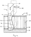
- FIG. 1 shows an embodiment of a sharp oscillating knife according to the prior art in oscillating cutting a composite plate 20.
- the blade 10 in this case has a cutting edge 16 extending over its entire extent straight (obliquely upward in the drawing) and thus over the entire edge profile a single common angle with the feed direction 52 includes, in which the knife is guided in the context of a Hubstichmodus along the composite plate.
- the composite panel 20 has an upper and a lower, respectively comparatively strong, heavy-walled wall 21, 22 and a comparatively light-weight intermediate layer 23 located therebetween Composite panel during the cutting process with its bottom wall 22 typically on a cutting pad 30 on.
- the cutting edge 16 forms zones within which, in the context of the stroke stitching mode, in particular only the bottom wall 22, especially essentially only the top wall 21 and especially essentially only the intermediate structure 23, are cut.
- the zones are identical in their course and the angles of intersection of the profiles within the zones are each optimized for cutting the material in the corresponding stroke stitching mode and in the corresponding field of application (as regards the operating speeds and sectional shapes of the parts).
- FIGS 2a-2h show four further embodiments of oscillating blades according to the prior art, each shown in two different views.
- FIG. 3a shows an oscillating according to a first inventive embodiment in oscillating cutting a composite plate of the aforementioned type with upper comparatively heavy-wall 21, lower comparatively heavy-wall 22 and comparativelytownroughiger intermediate structure 23.
- the composite plate is - as is known in the art and probably also typical in this application - on a cutting pad 30 on.
- the knife 1 according to the first exemplary embodiment is, for example, for composite panels of medium thickness (eg, having a thickness of about 16 mm in total) tuned.
- the respective profiles of the cutting edge 16 in the region of the first and second zones 12, 11 with the feed direction 52 each include a first angle of between approximately 30 ° and approximately 70 ° (in this case approximately 52 °).
- an intermediate zone 13 of the cutting edge 16 between the first and the second zone 12, 11 is present with a profile that includes a second angle with the feed direction 52, which is greater than the first angle, in particular greater than 90 °.
- this second angle 50 is approximately in the range between 100 ° and 120 °.
- the cutting edge 16 thus runs in the region of the intermediate zone 13 in such a manner - relative to the feed direction - obliquely behind, that overlap the progressions of the cutting edge within the first and the second zone 12, 11 - respectively orthogonally projected on the feed direction 52 - at least partially. In the example shown, they overlap This is essentially complete, so that the courses of the cutting edge within the first and second zones 12, 11 are substantially offset in parallel only in the direction orthogonal to the feed direction 52.
- the cutting edge within the first and the second zone 12, 11 can run in an essentially straight manner by way of example in each case.
- the cutting edge viewed in the course of the blade tip in the direction of the holding section, thus forms the first zone 12 in front of the intermediate zone 13 and the intermediate zone 13 in front of the second zone 11.
- FIG. 3b illustrates again exemplified the functional areas of the embodiment FIG. 3a trained knife.
- At least area 19 dives completely into the cutting base at the lowest stroke point.
- a part of area 12 can also dip into the cutting surface.
- the dot-dash line represents the surface of the cutting pad, just as the knife may be in the lowest stroke point configuration in a possible stroke stitch mode configuration.
- the length of the thick line determines with the stroke frequency the maximum feed rate, so that the material to be cut (ie the bottom wall of the composite panel) can still be completely cut.
- Areas 12 and 11 mainly intersect the hard layers (ie, upper wall) of the composite panel.
- Area 13 cuts the soft core.
- Area 15 (the holding section of the knife) is for attaching the knife in the cutting tool.
- FIGS. 4a to 4g show various views of the oscillating blade according to the first embodiment for illustrating various specific features.
- the knife 1 has a holding portion 15 for use desselbigen in a knife holder of a cutting tool and a blade 10 (wherein between holding portion 15 and blade 10 here is a little pronounced knife neck results).
- the blade has blade blade 17, blade 16 (the blade blade converges in a wedge-like manner at certain points in the direction of the blade) and a blade spine 18.
- FIGS. 4a-c shown views of the first inventive embodiment of an oscillating blade 1, in turn, the first zone 12, the intermediate zone 13 and the second zone 11 of the cutting edge 16 are indicated.
- the knife is designed with a flat blade tip.
- the blade extends over the entire blade tip and thus the blade tip has a flatter profile relative to the feed direction (i.e., less inclined to the direction of advance) as compared to the profile within the first zone.
- the cutting edge has a geometry which is axisymmetric in the lifting direction and has two blade tip zones which form a flat corner lying on the symmetry axis and respectively have profiles running less obliquely with respect to the feed direction than the profile within the first zone 12
- the profiles of the two Blade tip zones with the feed direction include angles of between about 2 ° and about 30 ° or of between about 150 ° and 178 °, in particular between about 10 ° and about 20 ° or between about 160 ° and 170 °, in particular as concrete in the example shown here - from about 15 ° or from about 165 °.
- Such a profile of the cutting edge in the region of the blade tip can be advantageous when the knife is immersed in the cutting support, since the knuckle or the symmetry in the blade tip ensures, on the one hand, a slightly oblique cutting edge progression over the entire blade tip area for the immersion and, on the other hand Nevertheless, the immersion depth in the pad - can be kept low (namely, can be halved) compared to an ungeknick slightly oblique tip.
- the knife or its geometry is specially adapted to the traversed feed rate and the stroke frequency, especially what the first angle 41, 42 (ie angle by the respective profiles within the first and second zone of the cutting edge with the feed direction), but also what the width 44 of the flat blade tip (ie extension of the tip in the feed direction) as well as the flatness 43 of the tip (ie extension of the tip in the stroke direction) concerns.
- These blade geometry parameters for the knife are in FIG. 4d specially marked.
- a stroke stitching mode which has a stroke of between about 0.2 and about 12 millimeters, a stroke frequency of between about 50 and about 800 Hz and a cutting speed in the feed direction of between about 0.1 and about 4 may be used for the cutting of corresponding sandwich panels Meters per second.
- the lift stitch mode may have a stroke of between about one and about five millimeters, more preferably between about two and about three millimeters, a stroke frequency of between about 100 and about 500 Hz, more preferably between about 200 and about 300 Hz, and a cutting speed in the feed direction of between about 0.5 and about 2 meters per second, in particular between about 0.75 and about 1.5 meters per second.
- the geometry of the knife according to the invention can thus advantageously be optimized especially for such a stroke stitch mode.
- the blade with the cutting edge can thus be advantageously designed - for example optimized for a lifting mode with a stroke of, for example, about 2.5 mm, a stroke frequency of, for example, about 250 Hz and a feed rate of, for example, about 1 m / s.
- the first angles 41, 42 enclosed by the respective profiles of the cutting edge in the region of the first and second zones are in each case between approximately 30 ° and approximately 70 °, in particular between approximately 45 ° and approximately 60 °, in particular approximately 52 ° ° is.
- the blade tip can be designed such that it has an extent or extension (ie width 44) in the feed direction of about 0.5-10 millimeters, in particular of between approximately 3 and about 6 millimeters, in particular of about 4.5 millimeters.
- Figure 4e Here is a sectional view AA of the blade of the knife shown, with the corresponding section AA in FIG. 4d is indexed. It is evident in this cross-sectional view AA - but in particular in the section Z pointing enlarged Figure 4g - The optional two-stage wedge-like course of the blade from the blade to blade 16 out.
- the first surfaces 48 of the cutting wedge directly forming the cutting edge 16 converge less sharply than converging second surfaces 49 of the wedge extending between the first surfaces 48 and the blade blade, particularly where the first surfaces 48 have a cutting angle 47 of between about 15 ° and 50 ° and the second surfaces 49 converge at an angle 46 that is less than the cutting angle 47 between about 3 ° and 20 °.
- the cutting angle 47 may advantageously be selected to be between about 25 ° and about 35 ° , in particular approximately at 30 °, and the angle 46 so that it is between about 5 and 12.5 ° smaller than the cutting angle 47, in particular at about 20 °.
- the thickness of the blade blade, with the two blade blade surfaces (i.e., front and back surfaces of the blade blade) advantageously aligned parallel to each other, may be, for example, between about 0.4 and about 3 millimeters.
- FIG. 4f is a sectional view BB - where the section BB in FIG. 4d is indicated - the blade of the knife shown.
- the optional one is apparent in this cross-sectional representation BB Characteristic that the two edges, which form the two blade surfaces with the back of the blade, can be chamfered.
- bevels e.g., at an angle of about 45 ° to the spine or blade surfaces
- an extension 45 in the feed direction of between about 0.05 and 2 mm (depending on the thickness of the blade blade).
- Such a chamfered blade back can bring advantages in particular when cutting radii (-> less friction, scratching and / or tilting with the material to be cut on the back of the blade) as well as the first vertical insertion of the blade into the material and pulling the blade at the end of a cutting.
- FIG. 5 shows the oscillating blade according to the first embodiment in the oscillating cutting of a composite plate, wherein the traversed in a special stroke stitching mode with strokes with sinusoidal velocity curve trajectory of the lower end of the first zone of the cutting edge is indicated (see thick sinusoidal line). With a thin sinusoidal line, the traversed travel path 55 of the lower end of the second zone of the cutting edge which intersects the top wall of the composite panel is indicated.
- the lifting movement itself is therefore designed to be linearly sinusoidal, so that combined from the two movements a sinusoidal curve results as a combined movement path 55.
- a lifting movement with uniform movement for lowering and also a uniform movement for lifting so that in Combination with the feed gives a sawtooth curve as the path).
- the cutting machine knife can be precisely provided for cutting the composite plate lying directly on a cutting surface, with the bottom wall, for which the blade with its blade tip - so matched to the composite panel to be cut and the Hubstichmodus provided for application - is designed that In the case of an oscillating cutting, the blade tip - when the cutting machine blade is lowered in stroke embossing mode - is inserted into the cutting surface in a cutting manner.
- FIG. 5 also seen from the course of the movement path 55 in conjunction with the illustrated first and second zones of the cutting edge and the lower and upper wall of the composite material - the blade with its blade tip so accurately matched to the composite panel to be cut and the intended application Hubstichmodus that - with each lowering the Schneidemaschinenmessers in Hubstickmodus - the lower wall is cut substantially exclusively with the first zone of the cutting edge and the blade tip and the upper wall substantially exclusively with the second zone of the cutting edge.
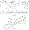
- Figures 6a-c show various views of an oscillating blade 1 according to a second embodiment of the invention.
- the second embodiment is with respect to almost all features identical to the first embodiment, except for the aspect that the knife according to the second embodiment is optimized and specially adapted for cutting relatively less thick composite panels (ie plates with less thick intermediate layer), ie composite panels of overall smaller thickness (eg, a thickness of about 10 mm in total).
- the intermediate zone 13 is - correspondingly shorter - compared to the knife according to the first embodiment. Furthermore, the first zone 12 - compared to the knife according to the first embodiment - be designed slightly shorter.
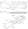
- FIGS. 7a-c show various views of an oscillating blade according to a third embodiment of the invention.
- the third embodiment is identical in almost all features with the first and second embodiments, except for the aspect that the knife according to the third embodiment is optimized and specially adapted for cutting comparatively thick composite panels (ie plates with thick intermediate layer), ie Composite panels of high overall thickness (eg having a total thickness of about 20 mm or more).
- the intermediate zone 13 is formed correspondingly longer in comparison to the knife according to the first embodiment and also has an additional section within this intermediate zone within which the cutting edge first extends at an angle of eg 90 ° relative to the feed direction, before then a section inside the intermediate zone follows with an angle of the local Cutting edge of eg between 105 ° and 120 ° relative to the feed direction.
- Figures 8a-c 8 show coarse sketches of oscillating knives according to a fourth, fifth and sixth embodiment according to the invention, which possible variations of the cutting geometry or the cutting profile, in particular in regions of the cutting edge within the intermediate zone 13 and the blade tip 19, can be taken from the principle.
Claims (15)
- Couteau pour machine à couper (1) pour l'utilisation dans un outil de coupe d'une machine à couper, configuré et prévu exactement pour couper un panneau composite à plusieurs parois (20) - en particulier un panneau sandwich- en un matériau à base de carton ou de carton épais ou en matière plastique qui présente une paroi supérieure et une paroi inférieure espacée de celle-ci, respectivement comparativement épaisse et difficile à couper (21, 22) et une couche intermédiaire située entre ces parois, comparativement facile à couper (23), en particulier en forme de structure d'une hauteur entre cinq et soixante millimètres en une matière avec des espaces creux, en particulier configuré comme une structure à motifs cellulaires se répétant ou en mousse,caractérisé en ce qu'une zone intermédiaire (13) du tranchant (16) existe entre la première et la seconde zone (12, 11) avec un profil qui forme un second angle (50) avec le sens d'avancement (52) qui est plus grand que le premier angle (41, 42), en particulier supérieur à 90°.• cependant que le couteau pour machine à couper (1) est prévu pour l'utilisation dans le cadre d'un mode de coupe automatique dans lequel le couteau pour machine à couper (1) est guidé à travers la machine à couper dans un sens d'avancement (52) le long du panneau composite (20),
présentant• une section de retenue (15) pour l'utilisation du couteau pour machine à couper (1) dans un support de couteau de l'outil de coupe et• une lame (10) avec un tranchant, cependant qu'une première zone (12) du tranchant (16) qui s'étend en oblique par rapport au sens d'avancement (52) est prévue pour couper la paroi inférieure (22) et une seconde zone (11) qui s'étend en oblique par rapport au sens d'avancement (52) est prévue pour couper la paroi supérieure (21), cependant que des profils respectifs du tranchant (16) dans la zone de la première et de la seconde zone (12, 11) forment, avec le sens d'avancement (52) respectivement un premier angle (41, 42) entre environ 30° et environ 70°, - Couteau pour machine à couper (1) selon la revendication 1, caractérisé en ce que le tranchant (16) dans la zone de la zone intermédiaire (13) s'étend en oblique vers l'arrière - par rapport au sens d'avancement (52) - de telle manière que les allures du tranchant (16) à l'intérieur de la première et de la seconde zone (12, 11) se chevauchent au moins partiellement - respectivement en projection orthogonale sur le sens d'avancement (52), en particulier qu'elles se chevauchent en particulier substantiellement entièrement, en particulier si bien que les allures du tranchant (16) à l'intérieur de la première et de la seconde zone (12, 11) sont substantiellement décalées parallèlement seulement dans le sens orthogonal par rapport au sens d'avancement (52).
- Couteau pour machine à couper (1) selon la revendication 1 ou 2, caractérisé en ce que le tranchant (16) a une allure respectivement substantiellement droite à l'intérieur de la première et de la seconde zone (12, 11).
- Couteau pour machine à couper (1) selon l'une des revendications précédentes, caractérisé en ce que des arêtes formées par le dos de la lame (18) et respectivement une surface avant et une surface arrière du plat de la lame (17) sont biseautées.
- Couteau pour machine à couper (1) selon l'une des revendications précédentes, caractérisé en ce que le tranchant (16) forme - ceci étant observé dans l'allure de la pointe de la lame (1) en direction de la section de retenue (15) - la première zone (12) devant la zone intermédiaire (13) et la zone intermédiaire (13) devant la seconde zone (11).
- Couteau pour machine à couper (1) selon l'une des revendications précédentes, caractérisé en ce que la lame (10) converge en forme de coin en deux degrés du plat de la lame (17) vers le tranchant (16), cependant que des premières surfaces (48) du coin qui forment directement le tranchant (16) convergent moins en pointe que des secondes surfaces convergentes (49) du coin qui s'étendent entre les premières surfaces (48) et le plat de la lame (17), en particulier cependant que les premières surfaces (48) forment un angle de coupe entre environ 15° et 50° et les secondes surfaces (49) convergent avec un angle qui est entre environ 3° et 20° plus petit que l'angle de coupe.
- Couteau pour machine à couper (1) selon l'une des revendications précédentes, caractérisé en ce que le couteau pour machine à couper (1) est configuré comme un outil de coupe oscillant et est prévu pour l'utilisation dans le cadre d'un mode de coupe par course de levage défini dans lequel le couteau pour machine à couper (1) est déplacé - en plus du guidage le long du sens d'avancement (52) - en oscillant en va-et-vient dans un sens de levage (51) substantiellement perpendiculairement au panneau composite (20) à couper, en particulier cependant que le mode de coupe par course de levage présente une course entre environ 0,2 et environ 12 millimètres, une fréquence de course entre environ 50 et environ 80 Hz ainsi qu'une vitesse de coupe dans le sens d'avancement (52) entre environ 0,1 et environ 4 mètres par seconde, en particulier cependant que le mode de coupe par course de levage présente une course entre environ un et environ cinq millimètres, en particulier entre environ deux et environ trois millimètres, en particulier environ 2,5 millimètres, une fréquence de course entre environ 100 et environ 500 Hz, en particulier entre environ 200 et environ 300 Hz, en particulier environ 250 Hz, ainsi qu'une vitesse de coupe dans le sens d'avancement (52) entre environ 0,5 et environ 2 mètres par seconde, en particulier entre environ 0,75 et environ 1,5 mètre par seconde, en particulier environ un mètre par seconde.
- Couteau pour machine à couper (1) selon la revendication 7, caractérisé en ce que le tranchant (16) s'étend sur toute la pointe de la lame (19) et la pointe de la lame (19) présente, en comparaison avec le profil à l'intérieur de la première zone (12), un profil plus plat en face du sens d'avancement (52).
- Couteau pour machine à couper (1) selon la revendication 7 ou 8, caractérisé en ce que le tranchant (16) présente, dans la zone de la pointe de la lame (19), une géométrique d'axe symétrique dans la direction de la course (51) avec deux zones de pointe de lame qui forment un coin plat situé sur l'axe de symétrie et qui présente des profils respectivement moins obliques par rapport au sens d'avancement (52) - en comparaison avec le profil à l'intérieur de la première zone (12), en particulier cependant que les profils des deux zones de pointe de lame forment, avec le sens d'avancement (52), des angles entre environ 2° et environ 30° et environ 30° ou entre environ 150° et 178°, en particulier entre environ 10° et environ 20° ou entre environ 160° et 170°, en particulier d'environ 15° ou d'environ 165°.
- Couteau pour machine à couper (1) selon l'une des revendications 7 à 9, caractérisé en ce que la pointe de la lame (19) présente une extension (44) dans le sens d'avancement (52) d'environ 0,5 à 10 millimètres, en particulier entre environ 3 et environ 6 millimètres, en particulier d'environ 4,5 millimètres.
- Couteau pour machine à couper (1) selon l'une des revendications 7 à 10, caractérisé en ce que le couteau pour machine à couper (1) est prévu exactement pour couper le panneau composite (20) posé avec la paroi inférieure (22) à plat directement sur un support pour découper (30), cependant que la lame (10) est configurée pour cela avec sa pointe de lame (19) - en étant adaptée au panneau composite à couper (20) et au mode de coupe par course de levage prévu pour l'application - de telle manière que, lors de la découpe oscillante, la pointe de la lame (19) plonge en coupant dans le support pour découper (30) - tout en abaissant respectivement le couteau pour machine à couper (1) dans le mode de coupe par course de levage, en particulier cependant que, au cas où le tranchant (16) présente, dans la zone de la pointe de la lame (19), une géométrie d'axe symétrique dans le sens d'avancement (51) selon la caractéristique de la revendication 9, une profondeur d'immersion du couteau dans le point le plus bas du mouvement d'oscillation est plus faible - en particulier de la moitié de la profondeur - que pour un couteau fictif correspondant avec un tranchant (16) qui n'est pas flambé mais qui est cependant oblique dans la zone de la pointe de la lame (19).
- Couteau pour machine à couper (1) selon l'une des revendications 7 à 10, caractérisé en ce que la lame (10) est configurée en étant adaptée exactement au panneau composite à couper (20) et au mode de coupe par course de levage prévu pour être appliqué de telle manière que la paroi inférieure (22) - avec un abaissement respectif du couteau pour machine à découper (1) dans le mode de coupe par course de levage - est coupée substantiellement exclusivement avec la première zone (12) du tranchant (16) et de la pointe de la lame (19) ainsi que la paroi supérieure (21) est coupée substantiellement exclusivement avec la seconde zone (11) du tranchant (16).
- Couteau pour machine à couper (1) selon l'une des revendications précédentes, caractérisé en ce que la lame (10) avec le tranchant (16) est configurée telle que le premier angle (41, 42) formé par les profils respectifs du tranchant (16) dans la zone de la première et de la seconde zone (12, 11) avec le sens d'avancement (52) est entre environ 40° et environ 65°, en particulier entre 45° et environ 60°, en particulier d'environ 52°.
- Machine à couper avec outil de coupe qui présente un support de couteau, machine dans laquelle un couteau pour machine à couper (1) selon l'une des revendications 1 à 13 est mis en oeuvre, cependant que la machine à couper met à disposition un mode de coupe dans lequel le couteau pour machine à couper (1) est guidé à travers la machine à couper dans un sens d'avancement (52) le long du panneau composite (20), dans lequel la machine à couper avec le couteau pour machine à couper mis en oeuvre (1) est configurée exactement et prévue pour couper un panneau composite à plusieurs parois (20) - en particulier un panneau sandwich - en un matériau à base de carton ou de carton épais ou en matière plastique qui présente une paroi supérieure et une paroi inférieure espacée de celle-ci, respectivement comparativement épaisse et difficile à couper (21, 22), et une couche intermédiaire située entre ces parois, comparativement facile à couper (23), en particulier en forme de structure d'une hauteur entre cinq et soixante millimètres en une matière avec des espaces creux, en particulier configuré comme une structure à motifs cellulaires se répétant ou en mousse, en particulier cependant que le couteau pour machine à couper (1) est configuré comme un couteau oscillant et l'outil de coupe comme un outil de coupe oscillant et que la machine à couper et l'outil de coupe mettent à disposition un mode de coupe par course de levage dans lequel le couteau pour machine à couper (1) est déplacé - en plus du guidage le long du sens d'avancement (52) - en oscillant en va-et-vient dans un sens de levage (51) substantiellement perpendiculairement au panneau composite (20) à couper, en particulier cependant que le mode de coupe par course de levage présente une course entre environ 0,2 et environ 12 millimètres, une fréquence de course entre environ 50 et environ 800 Hz ainsi qu'une vitesse de coupe dans le sens d'avancement (52) entre environ 0,1 et environ 4 mètres par seconde.
- Utilisation du couteau pour machine à couper (1) selon l'une des revendications 1 à 13 mis en oeuvre dans une machine à couper avec un outil de coupe.
Priority Applications (4)
| Application Number | Priority Date | Filing Date | Title |
|---|---|---|---|
| ES14150776T ES2572081T3 (es) | 2014-01-10 | 2014-01-10 | Cuchilla, en particular cuchilla oscilante, destinada al uso en un procedimiento de corte mecánico, para cortar placas sándwich |
| EP14150776.4A EP2894014B1 (fr) | 2014-01-10 | 2014-01-10 | Lame, en particulier lame oscillante, destinée à être utilisée dans un processus de découpe mécanique, pour la découpe de plaques de sandwich |
| CN201510058173.3A CN104772787B (zh) | 2014-01-10 | 2015-01-08 | 切割夹层板的机械切割法中使用的刀,尤其是振动刀 |
| US14/593,852 US20150266194A1 (en) | 2014-01-10 | 2015-01-09 | Blade, in particular oscillating blade, to be used in a machine cutting method for cutting sandwich plates |
Applications Claiming Priority (1)
| Application Number | Priority Date | Filing Date | Title |
|---|---|---|---|
| EP14150776.4A EP2894014B1 (fr) | 2014-01-10 | 2014-01-10 | Lame, en particulier lame oscillante, destinée à être utilisée dans un processus de découpe mécanique, pour la découpe de plaques de sandwich |
Publications (2)
| Publication Number | Publication Date |
|---|---|
| EP2894014A1 EP2894014A1 (fr) | 2015-07-15 |
| EP2894014B1 true EP2894014B1 (fr) | 2016-03-23 |
Family
ID=49917010
Family Applications (1)
| Application Number | Title | Priority Date | Filing Date |
|---|---|---|---|
| EP14150776.4A Active EP2894014B1 (fr) | 2014-01-10 | 2014-01-10 | Lame, en particulier lame oscillante, destinée à être utilisée dans un processus de découpe mécanique, pour la découpe de plaques de sandwich |
Country Status (4)
| Country | Link |
|---|---|
| US (1) | US20150266194A1 (fr) |
| EP (1) | EP2894014B1 (fr) |
| CN (1) | CN104772787B (fr) |
| ES (1) | ES2572081T3 (fr) |
Cited By (4)
| Publication number | Priority date | Publication date | Assignee | Title |
|---|---|---|---|---|
| EP3488983A1 (fr) | 2017-11-24 | 2019-05-29 | Zünd Systemtechnik Ag | Découpeuse |
| EP3689537A1 (fr) | 2019-02-01 | 2020-08-05 | Zünd Systemtechnik Ag | Machine à découper avec changement d'outil |
| EP4000814A1 (fr) | 2020-11-20 | 2022-05-25 | Zünd Systemtechnik Ag | Direction améliorée de la tête de préhension d'une pince de préhension d'un système de coupe numérique |
| US11400614B2 (en) | 2017-04-05 | 2022-08-02 | Zünd Systemtechnik Ag | Cutting machine with overview camera |
Families Citing this family (9)
| Publication number | Priority date | Publication date | Assignee | Title |
|---|---|---|---|---|
| KR101650789B1 (ko) * | 2012-09-28 | 2016-08-24 | 야마하하쓰도키 가부시키가이샤 | 부품 공급 유닛 |
| JP2020040176A (ja) * | 2018-09-11 | 2020-03-19 | 宮川工機株式会社 | 断熱材加工装置、断熱材加工装置の制御装置、及び、断熱材加工プログラム |
| AT521720A1 (de) | 2018-10-01 | 2020-04-15 | Gfm Gmbh | Verfahren zum Schneiden von Randfasen plattenförmiger Werkstücke |
| CN110000819A (zh) * | 2019-04-13 | 2019-07-12 | 张家港市文锋机械有限公司 | 一种塑料管材无屑切割的刀具 |
| IT201900006811A1 (it) * | 2019-05-14 | 2020-11-14 | Teseo Spa | Lama di taglio |
| EP3756842A1 (fr) * | 2019-06-24 | 2020-12-30 | Zünd Systemtechnik Ag | Plane de découpage par effleurement |
| CN111673804B (zh) * | 2020-07-20 | 2021-07-06 | 常州纳捷机电科技有限公司 | 一种坚硬板材的平刃切割方法 |
| CN114311044B (zh) * | 2022-03-14 | 2022-05-27 | 常州纳捷机电科技有限公司 | 一种碳纤维层合板的自动切割方法 |
| CN114523495B (zh) * | 2022-03-29 | 2023-05-26 | 苏州科技大学 | 一种具有曲线刃尖形刀具的超声振动切割刀及其使用方法 |
Family Cites Families (12)
| Publication number | Priority date | Publication date | Assignee | Title |
|---|---|---|---|---|
| US245150A (en) * | 1881-08-02 | Assigknoe to | ||
| US2757697A (en) * | 1950-06-07 | 1956-08-07 | Simmons | Slicing blade or band |
| US3033251A (en) * | 1960-07-07 | 1962-05-08 | Black & Decker Mfg Co | Double edged blades for sabre saw |
| US3680610A (en) * | 1971-03-04 | 1972-08-01 | Wallace I Lindgren | Sabre saw blade structure |
| US4131996A (en) * | 1977-06-27 | 1979-01-02 | Janke William R | Blade for cutting wallboard |
| US4133236A (en) * | 1977-11-29 | 1979-01-09 | Gerber Garment Technology, Inc. | Sharpenable cutting blade with skew-cut notches for use in sheet material cutting apparatus |
| US5295426A (en) * | 1992-06-15 | 1994-03-22 | Planchon Paul O | Slot starting sawing method and apparatus |
| US6782781B2 (en) * | 2001-07-23 | 2004-08-31 | Scandus Trading Company, Llc | Saw blade for reciprocating saw apparatus |
| WO2011133864A2 (fr) * | 2010-04-22 | 2011-10-27 | Milwaukee Electric Tool Corporation | Lame de scie |
| CN203045774U (zh) * | 2012-12-31 | 2013-07-10 | 苏州金纬机械制造有限公司 | 一种管件切割刀 |
| CN103112025B (zh) * | 2013-01-31 | 2015-05-13 | 铜陵格瑞特挤出技术有限公司 | 用于热切割塑料型材的切割刀 |
| CN103182720B (zh) * | 2013-03-26 | 2015-06-17 | 江苏科技大学 | 电磁激振式割刀 |
-
2014
- 2014-01-10 EP EP14150776.4A patent/EP2894014B1/fr active Active
- 2014-01-10 ES ES14150776T patent/ES2572081T3/es active Active
-
2015
- 2015-01-08 CN CN201510058173.3A patent/CN104772787B/zh active Active
- 2015-01-09 US US14/593,852 patent/US20150266194A1/en not_active Abandoned
Cited By (9)
| Publication number | Priority date | Publication date | Assignee | Title |
|---|---|---|---|---|
| US11400614B2 (en) | 2017-04-05 | 2022-08-02 | Zünd Systemtechnik Ag | Cutting machine with overview camera |
| US11712815B2 (en) | 2017-04-05 | 2023-08-01 | Zünd Systemtechnik Ag | Cutting machine with overview camera |
| EP4302948A2 (fr) | 2017-04-05 | 2024-01-10 | Zünd Systemtechnik Ag | Machine de coupe avec caméra de vision |
| EP4302949A2 (fr) | 2017-04-05 | 2024-01-10 | Zünd Systemtechnik Ag | Machine de coupe avec caméra de vision |
| EP4324609A2 (fr) | 2017-04-05 | 2024-02-21 | Zünd Systemtechnik Ag | Machine de coupe avec caméra de vision |
| EP3488983A1 (fr) | 2017-11-24 | 2019-05-29 | Zünd Systemtechnik Ag | Découpeuse |
| EP3689537A1 (fr) | 2019-02-01 | 2020-08-05 | Zünd Systemtechnik Ag | Machine à découper avec changement d'outil |
| US11667000B2 (en) | 2019-02-01 | 2023-06-06 | Zünd Systemtechnik Ag | Cutting machine |
| EP4000814A1 (fr) | 2020-11-20 | 2022-05-25 | Zünd Systemtechnik Ag | Direction améliorée de la tête de préhension d'une pince de préhension d'un système de coupe numérique |
Also Published As
| Publication number | Publication date |
|---|---|
| ES2572081T3 (es) | 2016-05-30 |
| EP2894014A1 (fr) | 2015-07-15 |
| US20150266194A1 (en) | 2015-09-24 |
| CN104772787A (zh) | 2015-07-15 |
| CN104772787B (zh) | 2019-06-04 |
Similar Documents
| Publication | Publication Date | Title |
|---|---|---|
| EP2894014B1 (fr) | Lame, en particulier lame oscillante, destinée à être utilisée dans un processus de découpe mécanique, pour la découpe de plaques de sandwich | |
| EP3031998B1 (fr) | Panneau avec une mécanisme de verrouillage mécanique en forme de crochet | |
| EP0487948B1 (fr) | Procédé et dispositif pour placer des caneaux dans la surface des matériaux panneaux doux et usage de ce dispositif | |
| DE3341651A1 (de) | Verfahren und vorrichtung zum herstellen von zuschnitten | |
| DE3623035C1 (de) | Verfahren und Vorrichtung zum Herstellen eines eine scharfe Schneidkante aufweisenden Stanzwerkzeugs | |
| DE102010061321A1 (de) | Verfahren zum Fräsen einer Ausnehmung in einem Werkstück und Werkstück mit einer Ausnehmung | |
| EP2886272B1 (fr) | Dispositif et méthode de traitement d'une pièce | |
| EP2642137B1 (fr) | Agrafeuse pour fixation de plaques d'isolation sur supports en bois | |
| DE2228476C3 (de) | Verfahren zum koordinatengesteuerten Schneiden einer mehrschichtigen Flachmaterialauflage | |
| DE3330452C2 (de) | Vorrichtung und Klinge zum Schneiden von Fasern enthaltendem Flachmaterial | |
| EP3885085A2 (fr) | Outil de poinçonnage | |
| EP1317974B1 (fr) | Procédé et machine pour fendre à plusieurs courses des pièces formés en plaque, en particulier des tôles | |
| EP3168016B1 (fr) | Outil de coupe destine a separer des materiaux plats | |
| DE2104293A1 (de) | Stanzvorrichtung | |
| EP1239989B1 (fr) | Fraise de chemins de roulement a billes, plaquette de coupe correspondante et procede pour la fabrication de roulement a billes | |
| EP3144076A1 (fr) | Outil pour une poinçonneuse pour transformer des sections d'une piece usinee en forme de plaque et procede associe | |
| EP0546392B1 (fr) | Lame pour le découpage ainsi que dispositif avec celle-ci | |
| DE102010061991B4 (de) | Verfahren zum Stanzen einer aus Fasermaterial bestehenden Fasermatte | |
| DE102018111366B4 (de) | Keiltrieb mit justierbarer Führungsvorrichtung | |
| DE2921176A1 (de) | Schlag- oder stanzeinrichtung | |
| DE202007013402U1 (de) | Schneidlinie | |
| DE3403668A1 (de) | Saege und verfahren zu ihrer herstellung | |
| DE202006021193U1 (de) | Vorrichtung zum Schneiden von plastischem Material | |
| DE2935182C2 (fr) | ||
| DE2129261A1 (de) | Filznadel fuer nadelfilzmaschinen |
Legal Events
| Date | Code | Title | Description |
|---|---|---|---|
| PUAI | Public reference made under article 153(3) epc to a published international application that has entered the european phase |
Free format text: ORIGINAL CODE: 0009012 |
|
| 17P | Request for examination filed |
Effective date: 20150309 |
|
| AK | Designated contracting states |
Kind code of ref document: A1 Designated state(s): AL AT BE BG CH CY CZ DE DK EE ES FI FR GB GR HR HU IE IS IT LI LT LU LV MC MK MT NL NO PL PT RO RS SE SI SK SM TR |
|
| AX | Request for extension of the european patent |
Extension state: BA ME |
|
| GRAP | Despatch of communication of intention to grant a patent |
Free format text: ORIGINAL CODE: EPIDOSNIGR1 |
|
| INTG | Intention to grant announced |
Effective date: 20150724 |
|
| RIC1 | Information provided on ipc code assigned before grant |
Ipc: B23D 61/12 20060101ALI20150713BHEP Ipc: B26D 1/06 20060101AFI20150713BHEP Ipc: B26D 1/00 20060101ALN20150713BHEP |
|
| GRAS | Grant fee paid |
Free format text: ORIGINAL CODE: EPIDOSNIGR3 |
|
| GRAA | (expected) grant |
Free format text: ORIGINAL CODE: 0009210 |
|
| AK | Designated contracting states |
Kind code of ref document: B1 Designated state(s): AL AT BE BG CH CY CZ DE DK EE ES FI FR GB GR HR HU IE IS IT LI LT LU LV MC MK MT NL NO PL PT RO RS SE SI SK SM TR |
|
| REG | Reference to a national code |
Ref country code: GB Ref legal event code: FG4D Free format text: NOT ENGLISH |
|
| REG | Reference to a national code |
Ref country code: CH Ref legal event code: EP |
|
| REG | Reference to a national code |
Ref country code: AT Ref legal event code: REF Ref document number: 782658 Country of ref document: AT Kind code of ref document: T Effective date: 20160415 Ref country code: CH Ref legal event code: NV Representative=s name: KAMINSKI HARMANN PATENTANWAELTE AG, LI |
|
| REG | Reference to a national code |
Ref country code: IE Ref legal event code: FG4D Free format text: LANGUAGE OF EP DOCUMENT: GERMAN |
|
| REG | Reference to a national code |
Ref country code: DE Ref legal event code: R096 Ref document number: 502014000478 Country of ref document: DE |
|
| REG | Reference to a national code |
Ref country code: ES Ref legal event code: FG2A Ref document number: 2572081 Country of ref document: ES Kind code of ref document: T3 Effective date: 20160530 |
|
| REG | Reference to a national code |
Ref country code: LT Ref legal event code: MG4D |
|
| REG | Reference to a national code |
Ref country code: NL Ref legal event code: MP Effective date: 20160323 |
|
| PG25 | Lapsed in a contracting state [announced via postgrant information from national office to epo] |
Ref country code: FI Free format text: LAPSE BECAUSE OF FAILURE TO SUBMIT A TRANSLATION OF THE DESCRIPTION OR TO PAY THE FEE WITHIN THE PRESCRIBED TIME-LIMIT Effective date: 20160323 Ref country code: GR Free format text: LAPSE BECAUSE OF FAILURE TO SUBMIT A TRANSLATION OF THE DESCRIPTION OR TO PAY THE FEE WITHIN THE PRESCRIBED TIME-LIMIT Effective date: 20160624 Ref country code: NO Free format text: LAPSE BECAUSE OF FAILURE TO SUBMIT A TRANSLATION OF THE DESCRIPTION OR TO PAY THE FEE WITHIN THE PRESCRIBED TIME-LIMIT Effective date: 20160623 Ref country code: HR Free format text: LAPSE BECAUSE OF FAILURE TO SUBMIT A TRANSLATION OF THE DESCRIPTION OR TO PAY THE FEE WITHIN THE PRESCRIBED TIME-LIMIT Effective date: 20160323 |
|
| PG25 | Lapsed in a contracting state [announced via postgrant information from national office to epo] |
Ref country code: RS Free format text: LAPSE BECAUSE OF FAILURE TO SUBMIT A TRANSLATION OF THE DESCRIPTION OR TO PAY THE FEE WITHIN THE PRESCRIBED TIME-LIMIT Effective date: 20160323 Ref country code: SE Free format text: LAPSE BECAUSE OF FAILURE TO SUBMIT A TRANSLATION OF THE DESCRIPTION OR TO PAY THE FEE WITHIN THE PRESCRIBED TIME-LIMIT Effective date: 20160323 Ref country code: NL Free format text: LAPSE BECAUSE OF FAILURE TO SUBMIT A TRANSLATION OF THE DESCRIPTION OR TO PAY THE FEE WITHIN THE PRESCRIBED TIME-LIMIT Effective date: 20160323 Ref country code: LV Free format text: LAPSE BECAUSE OF FAILURE TO SUBMIT A TRANSLATION OF THE DESCRIPTION OR TO PAY THE FEE WITHIN THE PRESCRIBED TIME-LIMIT Effective date: 20160323 Ref country code: LT Free format text: LAPSE BECAUSE OF FAILURE TO SUBMIT A TRANSLATION OF THE DESCRIPTION OR TO PAY THE FEE WITHIN THE PRESCRIBED TIME-LIMIT Effective date: 20160323 |
|
| PG25 | Lapsed in a contracting state [announced via postgrant information from national office to epo] |
Ref country code: EE Free format text: LAPSE BECAUSE OF FAILURE TO SUBMIT A TRANSLATION OF THE DESCRIPTION OR TO PAY THE FEE WITHIN THE PRESCRIBED TIME-LIMIT Effective date: 20160323 Ref country code: PL Free format text: LAPSE BECAUSE OF FAILURE TO SUBMIT A TRANSLATION OF THE DESCRIPTION OR TO PAY THE FEE WITHIN THE PRESCRIBED TIME-LIMIT Effective date: 20160323 Ref country code: IS Free format text: LAPSE BECAUSE OF FAILURE TO SUBMIT A TRANSLATION OF THE DESCRIPTION OR TO PAY THE FEE WITHIN THE PRESCRIBED TIME-LIMIT Effective date: 20160723 |
|
| PG25 | Lapsed in a contracting state [announced via postgrant information from national office to epo] |
Ref country code: RO Free format text: LAPSE BECAUSE OF FAILURE TO SUBMIT A TRANSLATION OF THE DESCRIPTION OR TO PAY THE FEE WITHIN THE PRESCRIBED TIME-LIMIT Effective date: 20160323 Ref country code: SM Free format text: LAPSE BECAUSE OF FAILURE TO SUBMIT A TRANSLATION OF THE DESCRIPTION OR TO PAY THE FEE WITHIN THE PRESCRIBED TIME-LIMIT Effective date: 20160323 Ref country code: SK Free format text: LAPSE BECAUSE OF FAILURE TO SUBMIT A TRANSLATION OF THE DESCRIPTION OR TO PAY THE FEE WITHIN THE PRESCRIBED TIME-LIMIT Effective date: 20160323 Ref country code: PT Free format text: LAPSE BECAUSE OF FAILURE TO SUBMIT A TRANSLATION OF THE DESCRIPTION OR TO PAY THE FEE WITHIN THE PRESCRIBED TIME-LIMIT Effective date: 20160725 Ref country code: CZ Free format text: LAPSE BECAUSE OF FAILURE TO SUBMIT A TRANSLATION OF THE DESCRIPTION OR TO PAY THE FEE WITHIN THE PRESCRIBED TIME-LIMIT Effective date: 20160323 |
|
| REG | Reference to a national code |
Ref country code: DE Ref legal event code: R097 Ref document number: 502014000478 Country of ref document: DE |
|
| REG | Reference to a national code |
Ref country code: FR Ref legal event code: PLFP Year of fee payment: 4 |
|
| PLBE | No opposition filed within time limit |
Free format text: ORIGINAL CODE: 0009261 |
|
| STAA | Information on the status of an ep patent application or granted ep patent |
Free format text: STATUS: NO OPPOSITION FILED WITHIN TIME LIMIT |
|
| PG25 | Lapsed in a contracting state [announced via postgrant information from national office to epo] |
Ref country code: DK Free format text: LAPSE BECAUSE OF FAILURE TO SUBMIT A TRANSLATION OF THE DESCRIPTION OR TO PAY THE FEE WITHIN THE PRESCRIBED TIME-LIMIT Effective date: 20160323 |
|
| PG25 | Lapsed in a contracting state [announced via postgrant information from national office to epo] |
Ref country code: BG Free format text: LAPSE BECAUSE OF FAILURE TO SUBMIT A TRANSLATION OF THE DESCRIPTION OR TO PAY THE FEE WITHIN THE PRESCRIBED TIME-LIMIT Effective date: 20160623 |
|
| 26N | No opposition filed |
Effective date: 20170102 |
|
| PG25 | Lapsed in a contracting state [announced via postgrant information from national office to epo] |
Ref country code: BE Free format text: LAPSE BECAUSE OF NON-PAYMENT OF DUE FEES Effective date: 20170131 Ref country code: SI Free format text: LAPSE BECAUSE OF FAILURE TO SUBMIT A TRANSLATION OF THE DESCRIPTION OR TO PAY THE FEE WITHIN THE PRESCRIBED TIME-LIMIT Effective date: 20160323 |
|
| PG25 | Lapsed in a contracting state [announced via postgrant information from national office to epo] |
Ref country code: MC Free format text: LAPSE BECAUSE OF FAILURE TO SUBMIT A TRANSLATION OF THE DESCRIPTION OR TO PAY THE FEE WITHIN THE PRESCRIBED TIME-LIMIT Effective date: 20160323 |
|
| REG | Reference to a national code |
Ref country code: IE Ref legal event code: MM4A |
|
| PG25 | Lapsed in a contracting state [announced via postgrant information from national office to epo] |
Ref country code: LU Free format text: LAPSE BECAUSE OF NON-PAYMENT OF DUE FEES Effective date: 20170110 |
|
| REG | Reference to a national code |
Ref country code: FR Ref legal event code: PLFP Year of fee payment: 5 |
|
| REG | Reference to a national code |
Ref country code: BE Ref legal event code: MM Effective date: 20170131 |
|
| PG25 | Lapsed in a contracting state [announced via postgrant information from national office to epo] |
Ref country code: IE Free format text: LAPSE BECAUSE OF NON-PAYMENT OF DUE FEES Effective date: 20170110 |
|
| PG25 | Lapsed in a contracting state [announced via postgrant information from national office to epo] |
Ref country code: MT Free format text: LAPSE BECAUSE OF FAILURE TO SUBMIT A TRANSLATION OF THE DESCRIPTION OR TO PAY THE FEE WITHIN THE PRESCRIBED TIME-LIMIT Effective date: 20160323 |
|
| PG25 | Lapsed in a contracting state [announced via postgrant information from national office to epo] |
Ref country code: AL Free format text: LAPSE BECAUSE OF FAILURE TO SUBMIT A TRANSLATION OF THE DESCRIPTION OR TO PAY THE FEE WITHIN THE PRESCRIBED TIME-LIMIT Effective date: 20160323 |
|
| PG25 | Lapsed in a contracting state [announced via postgrant information from national office to epo] |
Ref country code: HU Free format text: LAPSE BECAUSE OF FAILURE TO SUBMIT A TRANSLATION OF THE DESCRIPTION OR TO PAY THE FEE WITHIN THE PRESCRIBED TIME-LIMIT; INVALID AB INITIO Effective date: 20140110 |
|
| PG25 | Lapsed in a contracting state [announced via postgrant information from national office to epo] |
Ref country code: CY Free format text: LAPSE BECAUSE OF FAILURE TO SUBMIT A TRANSLATION OF THE DESCRIPTION OR TO PAY THE FEE WITHIN THE PRESCRIBED TIME-LIMIT Effective date: 20160323 |
|
| PG25 | Lapsed in a contracting state [announced via postgrant information from national office to epo] |
Ref country code: MK Free format text: LAPSE BECAUSE OF FAILURE TO SUBMIT A TRANSLATION OF THE DESCRIPTION OR TO PAY THE FEE WITHIN THE PRESCRIBED TIME-LIMIT Effective date: 20160323 |
|
| REG | Reference to a national code |
Ref country code: AT Ref legal event code: MM01 Ref document number: 782658 Country of ref document: AT Kind code of ref document: T Effective date: 20190110 |
|
| PG25 | Lapsed in a contracting state [announced via postgrant information from national office to epo] |
Ref country code: TR Free format text: LAPSE BECAUSE OF FAILURE TO SUBMIT A TRANSLATION OF THE DESCRIPTION OR TO PAY THE FEE WITHIN THE PRESCRIBED TIME-LIMIT Effective date: 20160323 |
|
| PG25 | Lapsed in a contracting state [announced via postgrant information from national office to epo] |
Ref country code: AT Free format text: LAPSE BECAUSE OF NON-PAYMENT OF DUE FEES Effective date: 20190110 |
|
| PGFP | Annual fee paid to national office [announced via postgrant information from national office to epo] |
Ref country code: FR Payment date: 20230125 Year of fee payment: 10 Ref country code: ES Payment date: 20230201 Year of fee payment: 10 Ref country code: CH Payment date: 20230125 Year of fee payment: 10 |
|
| PGFP | Annual fee paid to national office [announced via postgrant information from national office to epo] |
Ref country code: IT Payment date: 20230131 Year of fee payment: 10 Ref country code: GB Payment date: 20230122 Year of fee payment: 10 Ref country code: DE Payment date: 20230126 Year of fee payment: 10 |
|
| PGFP | Annual fee paid to national office [announced via postgrant information from national office to epo] |
Ref country code: ES Payment date: 20240201 Year of fee payment: 11 |