EP2894014B1 - Blade, in particular oscillating blade, for use in a mechanical cutting method, for cutting sandwich boards - Google Patents
Blade, in particular oscillating blade, for use in a mechanical cutting method, for cutting sandwich boards Download PDFInfo
- Publication number
- EP2894014B1 EP2894014B1 EP14150776.4A EP14150776A EP2894014B1 EP 2894014 B1 EP2894014 B1 EP 2894014B1 EP 14150776 A EP14150776 A EP 14150776A EP 2894014 B1 EP2894014 B1 EP 2894014B1
- Authority
- EP
- European Patent Office
- Prior art keywords
- cutting
- cutting machine
- blade
- edge
- stroke
- Prior art date
- Legal status (The legal status is an assumption and is not a legal conclusion. Google has not performed a legal analysis and makes no representation as to the accuracy of the status listed.)
- Active
Links
Images


Classifications
-
- B—PERFORMING OPERATIONS; TRANSPORTING
- B26—HAND CUTTING TOOLS; CUTTING; SEVERING
- B26D—CUTTING; DETAILS COMMON TO MACHINES FOR PERFORATING, PUNCHING, CUTTING-OUT, STAMPING-OUT OR SEVERING
- B26D1/00—Cutting through work characterised by the nature or movement of the cutting member or particular materials not otherwise provided for; Apparatus or machines therefor; Cutting members therefor
- B26D1/0006—Cutting members therefor
-
- B—PERFORMING OPERATIONS; TRANSPORTING
- B26—HAND CUTTING TOOLS; CUTTING; SEVERING
- B26D—CUTTING; DETAILS COMMON TO MACHINES FOR PERFORATING, PUNCHING, CUTTING-OUT, STAMPING-OUT OR SEVERING
- B26D1/00—Cutting through work characterised by the nature or movement of the cutting member or particular materials not otherwise provided for; Apparatus or machines therefor; Cutting members therefor
- B26D1/01—Cutting through work characterised by the nature or movement of the cutting member or particular materials not otherwise provided for; Apparatus or machines therefor; Cutting members therefor involving a cutting member which does not travel with the work
- B26D1/04—Cutting through work characterised by the nature or movement of the cutting member or particular materials not otherwise provided for; Apparatus or machines therefor; Cutting members therefor involving a cutting member which does not travel with the work having a linearly-movable cutting member
- B26D1/06—Cutting through work characterised by the nature or movement of the cutting member or particular materials not otherwise provided for; Apparatus or machines therefor; Cutting members therefor involving a cutting member which does not travel with the work having a linearly-movable cutting member wherein the cutting member reciprocates
-
- B—PERFORMING OPERATIONS; TRANSPORTING
- B26—HAND CUTTING TOOLS; CUTTING; SEVERING
- B26D—CUTTING; DETAILS COMMON TO MACHINES FOR PERFORATING, PUNCHING, CUTTING-OUT, STAMPING-OUT OR SEVERING
- B26D1/00—Cutting through work characterised by the nature or movement of the cutting member or particular materials not otherwise provided for; Apparatus or machines therefor; Cutting members therefor
- B26D1/56—Cutting through work characterised by the nature or movement of the cutting member or particular materials not otherwise provided for; Apparatus or machines therefor; Cutting members therefor involving a cutting member which travels with the work otherwise than in the direction of the cut, i.e. flying cutter
- B26D1/58—Cutting through work characterised by the nature or movement of the cutting member or particular materials not otherwise provided for; Apparatus or machines therefor; Cutting members therefor involving a cutting member which travels with the work otherwise than in the direction of the cut, i.e. flying cutter and is mounted on a movable arm or the like
- B26D1/585—Cutting through work characterised by the nature or movement of the cutting member or particular materials not otherwise provided for; Apparatus or machines therefor; Cutting members therefor involving a cutting member which travels with the work otherwise than in the direction of the cut, i.e. flying cutter and is mounted on a movable arm or the like for thin material, e.g. for sheets, strips or the like
-
- B—PERFORMING OPERATIONS; TRANSPORTING
- B26—HAND CUTTING TOOLS; CUTTING; SEVERING
- B26D—CUTTING; DETAILS COMMON TO MACHINES FOR PERFORATING, PUNCHING, CUTTING-OUT, STAMPING-OUT OR SEVERING
- B26D1/00—Cutting through work characterised by the nature or movement of the cutting member or particular materials not otherwise provided for; Apparatus or machines therefor; Cutting members therefor
- B26D1/0006—Cutting members therefor
- B26D2001/0053—Cutting members therefor having a special cutting edge section or blade section
-
- B—PERFORMING OPERATIONS; TRANSPORTING
- B26—HAND CUTTING TOOLS; CUTTING; SEVERING
- B26D—CUTTING; DETAILS COMMON TO MACHINES FOR PERFORATING, PUNCHING, CUTTING-OUT, STAMPING-OUT OR SEVERING
- B26D1/00—Cutting through work characterised by the nature or movement of the cutting member or particular materials not otherwise provided for; Apparatus or machines therefor; Cutting members therefor
- B26D1/0006—Cutting members therefor
- B26D2001/006—Cutting members therefor the cutting blade having a special shape, e.g. a special outline, serrations
-
- Y—GENERAL TAGGING OF NEW TECHNOLOGICAL DEVELOPMENTS; GENERAL TAGGING OF CROSS-SECTIONAL TECHNOLOGIES SPANNING OVER SEVERAL SECTIONS OF THE IPC; TECHNICAL SUBJECTS COVERED BY FORMER USPC CROSS-REFERENCE ART COLLECTIONS [XRACs] AND DIGESTS
- Y10—TECHNICAL SUBJECTS COVERED BY FORMER USPC
- Y10T—TECHNICAL SUBJECTS COVERED BY FORMER US CLASSIFICATION
- Y10T83/00—Cutting
- Y10T83/465—Cutting motion of tool has component in direction of moving work
- Y10T83/4749—Tool mounted on oscillating standard
-
- Y—GENERAL TAGGING OF NEW TECHNOLOGICAL DEVELOPMENTS; GENERAL TAGGING OF CROSS-SECTIONAL TECHNOLOGIES SPANNING OVER SEVERAL SECTIONS OF THE IPC; TECHNICAL SUBJECTS COVERED BY FORMER USPC CROSS-REFERENCE ART COLLECTIONS [XRACs] AND DIGESTS
- Y10—TECHNICAL SUBJECTS COVERED BY FORMER USPC
- Y10T—TECHNICAL SUBJECTS COVERED BY FORMER US CLASSIFICATION
- Y10T83/00—Cutting
- Y10T83/929—Tool or tool with support
- Y10T83/9454—Reciprocable type
Definitions
- the invention relates to a knife, in particular oscillating knife, for use in a particular oscillating cutting tool of a cutting machine according to the preamble of the independent claim 1.
- Maschinueller Oszillierschneidebacter and cutting machines with, for example, oscillating - that is driven - cutting tool and suitable for this oscillating, so that especially the cutting of a multi-wall composite panel - in particular sandwich panel - is provided, are known in the art.
- a multi-wall composite panel is understood to be a sandwich panel, in particular of cardboard or cardboard material or plastic, which is constructed from at least one upper and one spaced apart lower comparatively strong, heavy-walled wall and has a comparatively light-weighted intermediate layer therebetween, in particular in the form of an intermediate wall five and 60 mm high intermediate structure, the example from thin-walled cardboard or cardboard material - such as honeycomb structure - or lightweight plastic - such as foam - exists.
- the cutting machine and a correspondingly designed cutting tool for this purpose can provide a stroke stitching mode in which the plates can be cut or cut to size as desired.
- a knife inserted into a knife holder of the cutting tool by the cutting tool and the cutting machine in a stroke direction oscillating lowering and lifting substantially perpendicular to the composite sheet to be cut moves and guided in a feed direction along the composite plate.
- the stroke stitch mode may include a stroke of between about 0.2 and about 12 millimeters, a stroke frequency of between about 50 and about 800 Hz (with a sinusoidal linear sweep), and a feed rate of between about 0.1 and about 4 meters per inch Second.
- the oscillating movement of the knife reduces the pushing force in the direction of travel (also called the feed direction).
- the field of application for pointed knives is aimed in particular at the machining of fine radii and small parts.
- the feed rate should generally be reduced compared to the use of flat knives in order to achieve a sufficient cutting result.
- the subject invention relates to a cutting machine blade for use in a cutting tool of a cutting machine, designed and precisely provided for cutting a multi-wall composite panel - in particular sandwich panel - of cardboard or cardboard material or plastic, the at least one upper and a lower spaced respectively comparatively strong sheared wall and an intervening comparatively light interlayer, in particular in the form of a structure of between five and 60 millimeters high of material with cavities, in particular designed as a repeating cell pattern structure or foam.
- the cutting machine knife is intended for use in an automatic cutting mode in which the cutting machine knife is guided by the cutting machine in a feed direction along the composite board.
- the cutting blade is designed as a flat knife and provided for use in a cutting mode in which at relatively high speeds (feed speeds) large radii or straight lines or large parts are cut from composite panels.
- the cutting machine blade has a holding section for use of the cutting machine blade in a knife holder of the cutting tool and a blade with cutting edge.
- the cutting edge in the region of the intermediate zone may advantageously in particular in such a way - relative to the feed direction - extends obliquely behind, that the curves of the cutting edge within the first and the second zone - respectively orthogonally projected on the feed direction - overlap at least partially, in particular substantially completely overlap, in particular so that the progressions of the cutting edge within the first and second zones are substantially offset in parallel only in the direction orthogonal to the feed direction.
- the first zone of the cutting edge in the context of this invention is formed by that portion of the cutting edge, which is intended and made just to cut in a defined and then for this knife exactly intended cutting mode, the bottom wall of the composite plate.
- the second zone of the cutting edge in the context of this invention is formed by that portion of the cutting edge, which is intended and made just to cut in a defined and then for this knife exactly intended cutting mode, the upper wall of the composite plate.
- angles are to be understood that form a respective main course direction of the respective profiles in the respective zones with the feed direction (respectively smaller of the two angles formed between the vectors, considered when the respective vector suspension points of the two vectors are superposed). If a profile in a zone does not run straight, then a main profile of the profile is to be considered or a direction in which the profile in the corresponding zone extends substantially in the middle (thereby away from the blade tip corner in the direction of the knife neck).
- the course direction of a profile within a respective zone is therefore considered to be in the same direction as the cutting edge extends away from its origin in the blade tip (ie away from the blade tip in the direction of the blade neck or holding region of the blade which the blade point corner (bottom point) is not on the
- the back of the blade is located and between the blade tip and blade back a "reverting" tip section is formed - possibly also away from the blade tip corner in the direction of the back]).
- the intermediate region is now aligned suboptimally with respect to its cutting angle to the intermediate structure of the composite panel, which is likewise to be cut through.
- this drawback overall does not significantly affect the cutting result, since the intermediate structure consists of precisely cut material (in particular with cavities) and thus can be cut sufficiently well even with a suboptimal cutting angle.
- the invention may in particular be an oscillating blade for use in an oscillating cutting tool.
- the Oszilliermesser should then be designed so that it is specially designed and predestined for use in a defined Hubstichmodus in which the knife - in addition to the guide along the feed direction - by the cutting tool in a stroke direction oscillating up and down substantially perpendicular to cutting composite plate is moved.
- the stroke movement itself can be carried out in particular linearly sinusoidal, so that combined from the two movements results in a sinusoidal curve as a combined path of movement.
- the stroke stitch mode for which the knife is made may have a stroke of between about 0.2 and about 12 millimeters, a stroke frequency of between about 50 and about 800 Hz, and a feed rate of between about 0.1 and about 4 meters per inch Second.
- the oscillating cutting offers, for example, the advantage of cutting, which is carried out using a non-self-driven cutting tool with inserted pulling knife - for example, the advantages that the main cutting direction is substantially vertical instead of horizontal and thus the horizontal cutting forces are reduced (so that Technique is typically used for composite panels with comparatively thick, firm upper and lower walls).
- a knife which is specially designed and provided for cutting a multi-sandwich plate can also be designed such that the teaching of the invention has a plurality of wall cutting zones and a respective plurality of "receding" intermediate zones such that one adjoins an intermediate zone upwards Wall cutting zone (in comparison to downwardly adjoining wall cutting zone) by the course of the cutting edge within the intermediate zone to the rear (viewed in the feed direction) is added, in the sense of the teaching of the invention described above.
- the invention also relates to a cutting machine with cutting tool having a knife holder, in which a cutting machine blade according to the invention - as described above - is used.
- the cutting machine thereby provides a cutting mode in which the cutting machine blade is guided by the cutting machine in a feed direction along the composite plate.
- the cutting machine with the cutting machine blade used is then precisely designed and provided for cutting a multi-wall composite panel - in particular sandwich panel - of cardboard or cardboard material or plastic, which has at least one upper and a lower spaced comparatively strong heavy wall and at least one between them lying comparatively light interlayer, especially in the form of one between five and 60 millimeter high structure of material with cavities, specifically designed as a repeating cell pattern structure or foam.
- the invention relates to the use of the cutting machine blade according to the invention - as described above - used in a cutting machine with cutting tool and also a method for cutting composite panels of the aforementioned type using a cutting machine with cutting tool and inserted therein cutting machine blade (as described above).
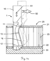
- FIG. 1 shows an embodiment of a sharp oscillating knife according to the prior art in oscillating cutting a composite plate 20.
- the blade 10 in this case has a cutting edge 16 extending over its entire extent straight (obliquely upward in the drawing) and thus over the entire edge profile a single common angle with the feed direction 52 includes, in which the knife is guided in the context of a Hubstichmodus along the composite plate.
- the composite panel 20 has an upper and a lower, respectively comparatively strong, heavy-walled wall 21, 22 and a comparatively light-weight intermediate layer 23 located therebetween Composite panel during the cutting process with its bottom wall 22 typically on a cutting pad 30 on.
- the cutting edge 16 forms zones within which, in the context of the stroke stitching mode, in particular only the bottom wall 22, especially essentially only the top wall 21 and especially essentially only the intermediate structure 23, are cut.
- the zones are identical in their course and the angles of intersection of the profiles within the zones are each optimized for cutting the material in the corresponding stroke stitching mode and in the corresponding field of application (as regards the operating speeds and sectional shapes of the parts).
- FIGS 2a-2h show four further embodiments of oscillating blades according to the prior art, each shown in two different views.
- FIG. 3a shows an oscillating according to a first inventive embodiment in oscillating cutting a composite plate of the aforementioned type with upper comparatively heavy-wall 21, lower comparatively heavy-wall 22 and comparativelytownroughiger intermediate structure 23.
- the composite plate is - as is known in the art and probably also typical in this application - on a cutting pad 30 on.
- the knife 1 according to the first exemplary embodiment is, for example, for composite panels of medium thickness (eg, having a thickness of about 16 mm in total) tuned.
- the respective profiles of the cutting edge 16 in the region of the first and second zones 12, 11 with the feed direction 52 each include a first angle of between approximately 30 ° and approximately 70 ° (in this case approximately 52 °).
- an intermediate zone 13 of the cutting edge 16 between the first and the second zone 12, 11 is present with a profile that includes a second angle with the feed direction 52, which is greater than the first angle, in particular greater than 90 °.
- this second angle 50 is approximately in the range between 100 ° and 120 °.
- the cutting edge 16 thus runs in the region of the intermediate zone 13 in such a manner - relative to the feed direction - obliquely behind, that overlap the progressions of the cutting edge within the first and the second zone 12, 11 - respectively orthogonally projected on the feed direction 52 - at least partially. In the example shown, they overlap This is essentially complete, so that the courses of the cutting edge within the first and second zones 12, 11 are substantially offset in parallel only in the direction orthogonal to the feed direction 52.
- the cutting edge within the first and the second zone 12, 11 can run in an essentially straight manner by way of example in each case.
- the cutting edge viewed in the course of the blade tip in the direction of the holding section, thus forms the first zone 12 in front of the intermediate zone 13 and the intermediate zone 13 in front of the second zone 11.
- FIG. 3b illustrates again exemplified the functional areas of the embodiment FIG. 3a trained knife.
- At least area 19 dives completely into the cutting base at the lowest stroke point.
- a part of area 12 can also dip into the cutting surface.
- the dot-dash line represents the surface of the cutting pad, just as the knife may be in the lowest stroke point configuration in a possible stroke stitch mode configuration.
- the length of the thick line determines with the stroke frequency the maximum feed rate, so that the material to be cut (ie the bottom wall of the composite panel) can still be completely cut.
- Areas 12 and 11 mainly intersect the hard layers (ie, upper wall) of the composite panel.
- Area 13 cuts the soft core.
- Area 15 (the holding section of the knife) is for attaching the knife in the cutting tool.
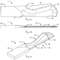
- FIGS. 4a to 4g show various views of the oscillating blade according to the first embodiment for illustrating various specific features.
- the knife 1 has a holding portion 15 for use desselbigen in a knife holder of a cutting tool and a blade 10 (wherein between holding portion 15 and blade 10 here is a little pronounced knife neck results).
- the blade has blade blade 17, blade 16 (the blade blade converges in a wedge-like manner at certain points in the direction of the blade) and a blade spine 18.
- FIGS. 4a-c shown views of the first inventive embodiment of an oscillating blade 1, in turn, the first zone 12, the intermediate zone 13 and the second zone 11 of the cutting edge 16 are indicated.
- the knife is designed with a flat blade tip.
- the blade extends over the entire blade tip and thus the blade tip has a flatter profile relative to the feed direction (i.e., less inclined to the direction of advance) as compared to the profile within the first zone.
- the cutting edge has a geometry which is axisymmetric in the lifting direction and has two blade tip zones which form a flat corner lying on the symmetry axis and respectively have profiles running less obliquely with respect to the feed direction than the profile within the first zone 12
- the profiles of the two Blade tip zones with the feed direction include angles of between about 2 ° and about 30 ° or of between about 150 ° and 178 °, in particular between about 10 ° and about 20 ° or between about 160 ° and 170 °, in particular as concrete in the example shown here - from about 15 ° or from about 165 °.
- Such a profile of the cutting edge in the region of the blade tip can be advantageous when the knife is immersed in the cutting support, since the knuckle or the symmetry in the blade tip ensures, on the one hand, a slightly oblique cutting edge progression over the entire blade tip area for the immersion and, on the other hand Nevertheless, the immersion depth in the pad - can be kept low (namely, can be halved) compared to an ungeknick slightly oblique tip.
- the knife or its geometry is specially adapted to the traversed feed rate and the stroke frequency, especially what the first angle 41, 42 (ie angle by the respective profiles within the first and second zone of the cutting edge with the feed direction), but also what the width 44 of the flat blade tip (ie extension of the tip in the feed direction) as well as the flatness 43 of the tip (ie extension of the tip in the stroke direction) concerns.
- These blade geometry parameters for the knife are in FIG. 4d specially marked.
- a stroke stitching mode which has a stroke of between about 0.2 and about 12 millimeters, a stroke frequency of between about 50 and about 800 Hz and a cutting speed in the feed direction of between about 0.1 and about 4 may be used for the cutting of corresponding sandwich panels Meters per second.
- the lift stitch mode may have a stroke of between about one and about five millimeters, more preferably between about two and about three millimeters, a stroke frequency of between about 100 and about 500 Hz, more preferably between about 200 and about 300 Hz, and a cutting speed in the feed direction of between about 0.5 and about 2 meters per second, in particular between about 0.75 and about 1.5 meters per second.
- the geometry of the knife according to the invention can thus advantageously be optimized especially for such a stroke stitch mode.
- the blade with the cutting edge can thus be advantageously designed - for example optimized for a lifting mode with a stroke of, for example, about 2.5 mm, a stroke frequency of, for example, about 250 Hz and a feed rate of, for example, about 1 m / s.
- the first angles 41, 42 enclosed by the respective profiles of the cutting edge in the region of the first and second zones are in each case between approximately 30 ° and approximately 70 °, in particular between approximately 45 ° and approximately 60 °, in particular approximately 52 ° ° is.
- the blade tip can be designed such that it has an extent or extension (ie width 44) in the feed direction of about 0.5-10 millimeters, in particular of between approximately 3 and about 6 millimeters, in particular of about 4.5 millimeters.
- Figure 4e Here is a sectional view AA of the blade of the knife shown, with the corresponding section AA in FIG. 4d is indexed. It is evident in this cross-sectional view AA - but in particular in the section Z pointing enlarged Figure 4g - The optional two-stage wedge-like course of the blade from the blade to blade 16 out.
- the first surfaces 48 of the cutting wedge directly forming the cutting edge 16 converge less sharply than converging second surfaces 49 of the wedge extending between the first surfaces 48 and the blade blade, particularly where the first surfaces 48 have a cutting angle 47 of between about 15 ° and 50 ° and the second surfaces 49 converge at an angle 46 that is less than the cutting angle 47 between about 3 ° and 20 °.
- the cutting angle 47 may advantageously be selected to be between about 25 ° and about 35 ° , in particular approximately at 30 °, and the angle 46 so that it is between about 5 and 12.5 ° smaller than the cutting angle 47, in particular at about 20 °.
- the thickness of the blade blade, with the two blade blade surfaces (i.e., front and back surfaces of the blade blade) advantageously aligned parallel to each other, may be, for example, between about 0.4 and about 3 millimeters.
- FIG. 4f is a sectional view BB - where the section BB in FIG. 4d is indicated - the blade of the knife shown.
- the optional one is apparent in this cross-sectional representation BB Characteristic that the two edges, which form the two blade surfaces with the back of the blade, can be chamfered.
- bevels e.g., at an angle of about 45 ° to the spine or blade surfaces
- an extension 45 in the feed direction of between about 0.05 and 2 mm (depending on the thickness of the blade blade).
- Such a chamfered blade back can bring advantages in particular when cutting radii (-> less friction, scratching and / or tilting with the material to be cut on the back of the blade) as well as the first vertical insertion of the blade into the material and pulling the blade at the end of a cutting.
- FIG. 5 shows the oscillating blade according to the first embodiment in the oscillating cutting of a composite plate, wherein the traversed in a special stroke stitching mode with strokes with sinusoidal velocity curve trajectory of the lower end of the first zone of the cutting edge is indicated (see thick sinusoidal line). With a thin sinusoidal line, the traversed travel path 55 of the lower end of the second zone of the cutting edge which intersects the top wall of the composite panel is indicated.
- the lifting movement itself is therefore designed to be linearly sinusoidal, so that combined from the two movements a sinusoidal curve results as a combined movement path 55.
- a lifting movement with uniform movement for lowering and also a uniform movement for lifting so that in Combination with the feed gives a sawtooth curve as the path).
- the cutting machine knife can be precisely provided for cutting the composite plate lying directly on a cutting surface, with the bottom wall, for which the blade with its blade tip - so matched to the composite panel to be cut and the Hubstichmodus provided for application - is designed that In the case of an oscillating cutting, the blade tip - when the cutting machine blade is lowered in stroke embossing mode - is inserted into the cutting surface in a cutting manner.
- FIG. 5 also seen from the course of the movement path 55 in conjunction with the illustrated first and second zones of the cutting edge and the lower and upper wall of the composite material - the blade with its blade tip so accurately matched to the composite panel to be cut and the intended application Hubstichmodus that - with each lowering the Schneidemaschinenmessers in Hubstickmodus - the lower wall is cut substantially exclusively with the first zone of the cutting edge and the blade tip and the upper wall substantially exclusively with the second zone of the cutting edge.
- Figures 6a-c show various views of an oscillating blade 1 according to a second embodiment of the invention.
- the second embodiment is with respect to almost all features identical to the first embodiment, except for the aspect that the knife according to the second embodiment is optimized and specially adapted for cutting relatively less thick composite panels (ie plates with less thick intermediate layer), ie composite panels of overall smaller thickness (eg, a thickness of about 10 mm in total).
- the intermediate zone 13 is - correspondingly shorter - compared to the knife according to the first embodiment. Furthermore, the first zone 12 - compared to the knife according to the first embodiment - be designed slightly shorter.
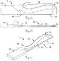
- FIGS. 7a-c show various views of an oscillating blade according to a third embodiment of the invention.
- the third embodiment is identical in almost all features with the first and second embodiments, except for the aspect that the knife according to the third embodiment is optimized and specially adapted for cutting comparatively thick composite panels (ie plates with thick intermediate layer), ie Composite panels of high overall thickness (eg having a total thickness of about 20 mm or more).
- the intermediate zone 13 is formed correspondingly longer in comparison to the knife according to the first embodiment and also has an additional section within this intermediate zone within which the cutting edge first extends at an angle of eg 90 ° relative to the feed direction, before then a section inside the intermediate zone follows with an angle of the local Cutting edge of eg between 105 ° and 120 ° relative to the feed direction.
- Figures 8a-c 8 show coarse sketches of oscillating knives according to a fourth, fifth and sixth embodiment according to the invention, which possible variations of the cutting geometry or the cutting profile, in particular in regions of the cutting edge within the intermediate zone 13 and the blade tip 19, can be taken from the principle.
Description
Die Erfindung betrifft ein Messer, insbesondere Oszilliermesser, zum Einsatz in ein insbesondere oszillierendes Schneidwerkzeug einer Schneidemaschine nach dem Oberbegriff des unabhängigen Anspruchs 1.The invention relates to a knife, in particular oscillating knife, for use in a particular oscillating cutting tool of a cutting machine according to the preamble of the
Maschinelle Oszillierschneideverfahren und Schneidemaschinen mit beispielsweise oszillierendem - also angetriebenem - Schneidwerkzeug sowie dafür geeignete Oszilliermesser, sodass damit speziell das Schneiden von einer mehrwandigen Verbundplatte - insbesondere Sandwichplatte - vorgesehen ist, sind im Stand der Technik bekannt.Maschinueller Oszillierschneideverfahren and cutting machines with, for example, oscillating - that is driven - cutting tool and suitable for this oscillating, so that especially the cutting of a multi-wall composite panel - in particular sandwich panel - is provided, are known in the art.
Als mehrwandige Verbundplatte wird in diesem Zusammenhang eine Sandwichplatte insbesondere aus Karton- oder Pappmaterial oder Kunststoff verstanden, die aus mindestens einer oberen und einer dazu beabstandeten unteren jeweils vergleichsweise starken schwerschnittigen Wand aufgebaut ist und eine dazwischen liegende vergleichsweise leichtschnittige Zwischenschicht aufweist, insbesondere in Form einer zwischen fünf und 60 Millimeter hohen ZwischenStruktur, die z.B. aus dünnwandigem Karton- oder Pappmaterial - etwa ausgebildet als Wabenstruktur - oder leichtem Kunststoff - etwa Schaumstoff - besteht.In this context, a multi-wall composite panel is understood to be a sandwich panel, in particular of cardboard or cardboard material or plastic, which is constructed from at least one upper and one spaced apart lower comparatively strong, heavy-walled wall and has a comparatively light-weighted intermediate layer therebetween, in particular in the form of an intermediate wall five and 60 mm high intermediate structure, the example from thin-walled cardboard or cardboard material - such as honeycomb structure - or lightweight plastic - such as foam - exists.
Zum Schneiden derartiger Platten ist es bekannt, dass die Schneidemaschine und ein entsprechend ausgebildetes Schneidwerkzeug dafür einen Hubstichmodus bereitstellen können, in welchem die Platten geschnitten bzw. wie gewünscht zugeschnitten werden können. Z.B. kann in einem solchen Hubstichmodus ein in eine Messerhalterung des Schneidwerkzeugs eingesetztes Messer durch das Schneidwerkzeug und die Schneidemaschine in einer Hubrichtung oszillierend senkend und hebend im Wesentlichen senkrecht zur zu schneidenden Verbundplatte bewegt sowie in einer Vorschubrichtung entlang der Verbundplatte geführt werden. Insbesondere kann dabei beispielhaft der Hubstichmodus einen Hub von zwischen etwa 0.2 und etwa 12 Millimeter, eine Hubfrequenz von zwischen etwa 50 und etwa 800 Hz (mit einer sinusartigen linearen Hubbewegung) sowie eine Schneidegeschwindigkeit in Vorschubrichtung von zwischen etwa 0,1 und etwa 4 Metern pro Sekunde aufweisen.For cutting such plates, it is known that the cutting machine and a correspondingly designed cutting tool for this purpose can provide a stroke stitching mode in which the plates can be cut or cut to size as desired. For example, in one such Hubstichmodus a knife inserted into a knife holder of the cutting tool by the cutting tool and the cutting machine in a stroke direction oscillating lowering and lifting substantially perpendicular to the composite sheet to be cut moves and guided in a feed direction along the composite plate. In particular, by way of example, the stroke stitch mode may include a stroke of between about 0.2 and about 12 millimeters, a stroke frequency of between about 50 and about 800 Hz (with a sinusoidal linear sweep), and a feed rate of between about 0.1 and about 4 meters per inch Second.
Das oszillierende Schneiden bietet - gegenüber z.B. dem Ziehschneiden, das unter Anwendung eines nicht selbst angetriebenen Schneidwerkzeugs mit eingesetztem Ziehmesser erfolgt - z.B. folgende Vorteile:
- Die Hauptschneidrichtung ist im Wesentlichen vertikal statt horizontal. Die horizontalen Schneidkräfte sind verringert.
- The main cutting direction is essentially vertical rather than horizontal. The horizontal cutting forces are reduced.
Wie dem Fachmann bekannt eignet sich die oszillierende Bearbeitung dabei insbesondere zum Schneiden von dicken und zähen Werkstoffen. Durch die oszillierende Bewegung des Messers wird die Schiebekraft in Fahrtrichtung (auch Vorschubrichtung genannt) reduziert.As known to those skilled in the oscillating processing is particularly suitable for cutting thick and tough materials. The oscillating movement of the knife reduces the pushing force in the direction of travel (also called the feed direction).
Allerdings muss die Vorschubgeschwindigkeit auf die Messergeometrie und die Oszillierfrequenz des eingesetzten Werkzeugs angepasst werden. Die Wahl des richtigen Oszilliermessers hängt vor allem von der Bearbeitungskontur ab:
- Für grosse Radien, Geraden und grosse Teile empfiehlt es sich tendenziell eher abgeflachte Messer zu verwenden.
- For large radii, straight lines and large parts, it is recommended to use rather flattened knives.
Das Einsatzgebiet für spitze Messer richtet sich insbesondere auf die Bearbeitung feiner Radien und kleiner Teile. Die Vorschubgeschwindigkeit sollte dabei in der Regel gegenüber der Verwendung von flachen Messern reduziert werden, um ein hinreichendes Schneidergebnis zu erzielen.The field of application for pointed knives is aimed in particular at the machining of fine radii and small parts. The feed rate should generally be reduced compared to the use of flat knives in order to achieve a sufficient cutting result.
Vergleichsweise flache Messer (siehe
- Hohe Bearbeitungsgeschwindigkeit
- Grosse Radien, Geraden bzw. grosse Teile
- High processing speed
- Large radii, straight lines or large parts
Vergleichsweise spitze Messer (siehe
- Geringe Bearbeitungsgeschwindigkeit
- Feine Radien bzw. kleine Teile
- Low processing speed
- Fine radii or small parts
Als Nachteil bei der Verwendung von vergleichsweise flachen Messern - also jenen Messern, die für das Einsatzgebiet mit hohen Bearbeitungsgeschwindigkeiten und grossen Radien, Geraden bzw. grossen Teilen bestimmt sind - hat sich erwiesen, dass - je nach Winkel der Schneide (also "Steile" des Verlaufs der Schneide) entweder der Schnittwinkel suboptimal (da zu steil) gewählt sein muss oder - bei flachem Schneidenverlauf - beim Schneiden von Formteilen aus dicken Verbundplatten (wie Sandwichplatten mit mindestens zwei starken Wänden und zwischenliegender Struktur), welche insgesamt dann z.B. 10, 16 oder 20 mm dick sein können, jeweils unerwünschte Überschnitte im Material erforderlich sind, was u.a. auch die Berechnung der Schneidpfade verkompliziert.A disadvantage in the use of relatively flat blades - ie those knives, which are intended for the field of application with high processing speeds and large radii, straight lines or large parts - has been found that - depending on the angle of the cutting edge (ie "Steile" of The cutting edge) either the cutting angle suboptimal (because too steep) must be selected or - with flat cutting profile - when cutting moldings from thick composite panels (such as sandwich panels with at least two strong walls and intermediate structure), which in total then
Es stellt sich somit die Aufgabe, ein verbessertes Messer zum Einsatz in ein Schneidwerkzeug einer Schneidemaschine bereitzustellen, welches bestimmt und vorgesehen ist zum Schneiden von Verbundplatten wie Sandwichplatten, insbesondere wobei das Messer bestimmt ist für hohe Bearbeitungsgeschwindigkeiten und grosse Radien, Geraden bzw. grosse Teile.It is therefore an object to provide an improved knife for use in a cutting tool of a cutting machine, which is intended and intended for cutting composite panels such as sandwich panels, in particular wherein the knife is intended for high processing speeds and large radii, straight lines or large parts.
Insbesondere sollen dabei die oben genannten Nachteile der für diesen speziellen Einsatzbereich bisher zur Anwendung kommenden flachen Oszilliermesser verringert bzw. behoben werden. Insbesondere soll dabei eine bessere Zielkonfliktlösung bereitgestellt werden zwischen steilem Verlauf der Schneide mit dann suboptimalem Schnittwinkel (dafür wenig Überschnitt) und flachem (weniger stark gegenüber der Vorschubrichtung geneigtem) Verlauf der Schneide mit optimiertem Schnittwinkel (dafür aber mit erheblichem unerwünschtem Überschnitt).In particular, the abovementioned disadvantages of the flat oscillating blades hitherto used for this special field of use are intended to be reduced or eliminated. In particular, a better goal conflict solution is to be provided between a steep course of the cutting edge with then suboptimal cutting angle (for little overcut) and flat (less steeply inclined with respect to the feed direction) course of the cutting edge with optimized cutting angle (but with considerable unwanted overcut).
Diese Aufgaben werden durch die Verwirklichung der kennzeichnenden Merkmale der unabhängigen Ansprüche gelöst. Merkmale, die die Erfindung in alternativer oder vorteilhafter Weise weiterbilden, sind den abhängigen Patentansprüchen zu entnehmen.These objects are achieved by the realization of the characterizing features of the independent claims. Features which further develop the invention in an alternative or advantageous manner can be found in the dependent claims.
Der erfindungsgemässe Gegenstand betrifft ein Schneidemaschinenmesser zum Einsatz in ein Schneidwerkzeug einer Schneidemaschine, ausgebildet und genau vorgesehen zum Schneiden von einer mehrwandigen Verbundplatte - insbesondere Sandwichplatte - aus Karton- oder Pappmaterial oder Kunststoff, die mindestens eine obere und eine dazu beabstandete untere jeweils vergleichsweise starke schwerschnittige Wand aufweist und eine dazwischen liegende vergleichsweise leichtschnittige Zwischenschicht, insbesondere in Form einer zwischen fünf und 60 Millimeter hohen Struktur aus Material mit Hohlräumen, im Speziellen ausgebildet als sich wiederholende Zellmusterstruktur oder aus Schaumstoff.The subject invention relates to a cutting machine blade for use in a cutting tool of a cutting machine, designed and precisely provided for cutting a multi-wall composite panel - in particular sandwich panel - of cardboard or cardboard material or plastic, the at least one upper and a lower spaced respectively comparatively strong sheared wall and an intervening comparatively light interlayer, in particular in the form of a structure of between five and 60 millimeters high of material with cavities, in particular designed as a repeating cell pattern structure or foam.
Das Schneidemaschinenmesser ist dabei vorgesehen zur Verwendung im Rahmen eines automatischen Schneidmodus, in welchem das Schneidemaschinenmesser durch die Schneidemaschine in einer Vorschubrichtung entlang der Verbundplatte geführt wird. Insbesondere ist das Schneidmesser dabei als flaches Messer ausgeführt und zur Verwendung in einem Schneidmodus vorgesehen, in welchem in vergleichsweise hohen Bearbeitungsgeschwindigkeiten (Vorschubgeschwindigkeiten) grosse Radien oder Geraden bzw. grosse Teile aus Verbundplatten geschnitten werden.The cutting machine knife is intended for use in an automatic cutting mode in which the cutting machine knife is guided by the cutting machine in a feed direction along the composite board. In particular, the cutting blade is designed as a flat knife and provided for use in a cutting mode in which at relatively high speeds (feed speeds) large radii or straight lines or large parts are cut from composite panels.
Das Schneidemaschinenmesser weist dabei einen Halteabschnitt zum Einsatz des Schneidemaschinenmessers in eine Messerhalterung des Schneidwerkzeugs und eine Klinge mit Schneide auf.The cutting machine blade has a holding section for use of the cutting machine blade in a knife holder of the cutting tool and a blade with cutting edge.
Erfindungsgemäss ist die Klinge nun so eingeteilt bzw. die Geometrie der Schneide derart gewählt, dass
- eine erste relativ zur Vorschubrichtung schräg verlaufende Zone der Schneide zum Schneiden der unteren Wand vorgesehen ist,
- eine zweite relativ zur Vorschubrichtung schräg verlaufende Zone der Schneide zum Schneiden der oberen Wand vorgesehen ist, wobei jeweilige Profile der Schneide im Bereich der ersten und zweiten Zone mit der Vorschubrichtung jeweils einen ersten Winkel von zwischen etwa 30° und etwa 70° einschliessen, und dass
- eine Zwischenzone der Schneide zwischen der ersten und der zweiten Zone vorhanden ist mit einem Profil, das einen zweiten Winkel mit der Vorschubrichtung einschliesst, welcher grösser ist als der erste Winkel, insbesondere grösser ist als 90°.
- a first zone of the cutting edge inclined relative to the feed direction is provided for cutting the lower wall,
- a second inclined relative to the feed direction zone of the cutting edge for cutting the upper wall is provided, wherein respective profiles of the cutting edge in the region of the first and second zone with the feed direction each include a first angle of between about 30 ° and about 70 °, and
- an intermediate zone of the cutting edge between the first and the second zone is present with a profile which encloses a second angle with the feed direction, which is greater than the first angle, in particular greater than 90 °.
Dadurch kann nun erfindungsgemäss erreicht werden, dass beim Schneiden von Formteilen aus betreffenden Verbundplatten (wie Sandwichplatten mit mindestens zwei starken Wänden und zwischenliegender Struktur, die beispielsweise insgesamt z.B. 10, 16 oder 20 mm dick sein können), jeweils unerwünschte Überschnitte im Material vermindert oder gar gänzlich vermieden werden können, was u.a. auch die Berechnung der Schneidpfade deutlich vereinfachen kann. Durch die Erfindung können nun die obere und untere Wand der Verbundplatte in Vorschubrichtung mit im Wesentlichen gleichem Schneidefortschritt geschnitten werden, ohne dass die obere Platte zu identischen Zeitpunkten jeweils immer bereits signifikant weiter geschnitten ist als die untere (bzw. der Schnitt in der unteren Wand dem Schnitt in der oberen Wand jeweils signifikant nachhängt).This can now be achieved according to the invention that when cutting moldings from relevant composite panels (such as sandwich panels with at least two strong walls and intermediate structure, which may be, for example, a total of 10, 16 or 20 mm thick, for example), respectively unwanted overcuts in the material reduced or even can be completely avoided, what among other things also significantly simplify the calculation of the cutting paths. By means of the invention, the upper and lower walls of the composite panel can now be cut in the feed direction with essentially the same cutting advance, without the upper panel always being significantly further cut at identical times than the lower one (or the section in the lower wall) Section in the upper wall in each case significantly nachhängt).
Die Schneide im Bereich der Zwischenzone kann vorteilhaft dabei insbesondere derart - relativ zur Vorschubrichtung - nach schräg hinten verläuft, dass sich die Verläufe der Schneide innerhalb der ersten und der zweiten Zone - jeweils orthogonal projiziert auf die Vorschubrichtung - zumindest teilweise überlappen, insbesondere im Wesentlichen vollständig überlappen, im Speziellen sodass die Verläufe der Schneide innerhalb der ersten und zweiten Zone im Wesentlichen parallel nur in zur Vorschubrichtung orthogonalen Richtung versetzt vorliegen.The cutting edge in the region of the intermediate zone may advantageously in particular in such a way - relative to the feed direction - extends obliquely behind, that the curves of the cutting edge within the first and the second zone - respectively orthogonally projected on the feed direction - overlap at least partially, in particular substantially completely overlap, in particular so that the progressions of the cutting edge within the first and second zones are substantially offset in parallel only in the direction orthogonal to the feed direction.
Die erste Zone der Schneide im Sinne dieser Erfindung wird dabei durch jenen Abschnitt der Schneide gebildet, der genau dafür vorgesehen und gemacht ist, um in einem definierten und für dieses Messer dann genau vorgesehenen Schneidemodus die untere Wand der Verbundplatte zu schneiden. Die zweite Zone der Schneide im Sinne dieser Erfindung wird dabei durch jenen Abschnitt der Schneide gebildet, der genau dafür vorgesehen und gemacht ist, um in einem definierten und für dieses Messer dann genau vorgesehenen Schneidemodus die obere Wand der Verbundplatte zu schneiden.The first zone of the cutting edge in the context of this invention is formed by that portion of the cutting edge, which is intended and made just to cut in a defined and then for this knife exactly intended cutting mode, the bottom wall of the composite plate. The second zone of the cutting edge in the context of this invention is formed by that portion of the cutting edge, which is intended and made just to cut in a defined and then for this knife exactly intended cutting mode, the upper wall of the composite plate.
Unter den zuvor genannten und auch im Folgenden angegebenen Winkeln, die die jeweiligen Profile der Schneide in den jeweiligen Zonen mit der Vorschubrichtung bilden, sind dabei Winkel zu verstehen, die eine jeweilige Hauptverlaufsrichtung der jeweiligen Profile in den jeweiligen Zonen mit der Vorschubrichtung bilden (jeweils der kleinere der beiden zwischen den Vektoren gebildeten Winkel, betrachtet wenn die jeweiligen Vektoraufhängepunkte der zwei Vektoren aufeinander gelegt werden). Verläuft ein Profil in einer Zone dabei nicht gerade, so ist also ein Hauptverlauf des Profils zu betrachten bzw. eine Richtung, in welcher das Profil in der entsprechenden Zone in Wesentlichen im Mittel verläuft (dabei von der Klingenspitzenecke weg in Richtung des Messerhalses). Die Verlaufsrichtung eines Profils innerhalb einer jeweiligen Zone wird hierfür somit dabei in jener Grundrichtung betrachtet, wie die Schneide von ihrem Ursprung in der Klingenspitze weg verläuft (d.h. von der Klingenspitze weg in Richtung des Messerhalses bzw. des Haltebereichs des Messers [sowie - in Ausführungsformen bei welchen die Klingenspitzenecke (unterster Punkt) nicht auf dem Klingenrücken liegt und zwischen Klingenspitze und Klingenrücken ein "rückschneidender" Spitzenabschnitt ausgebildet ist - ggf. auch von der Klingenspitzenecke weg in Richtung des Rückens]).Among the abovementioned angles and also mentioned below, which form the respective profiles of the cutting edge in the respective zones with the feed direction, angles are to be understood that form a respective main course direction of the respective profiles in the respective zones with the feed direction (respectively smaller of the two angles formed between the vectors, considered when the respective vector suspension points of the two vectors are superposed). If a profile in a zone does not run straight, then a main profile of the profile is to be considered or a direction in which the profile in the corresponding zone extends substantially in the middle (thereby away from the blade tip corner in the direction of the knife neck). The course direction of a profile within a respective zone is therefore considered to be in the same direction as the cutting edge extends away from its origin in the blade tip (ie away from the blade tip in the direction of the blade neck or holding region of the blade which the blade point corner (bottom point) is not on the The back of the blade is located and between the blade tip and blade back a "reverting" tip section is formed - possibly also away from the blade tip corner in the direction of the back]).
Als Folge des erfindungsgemässen Rückversetzens der zweiten Zone des Messers ist dabei zwar nun der Zwischenbereich hinsichtlich seines Schnittwinkels zur ebenso zu durchschneidenden Zwischenstruktur der Verbundplatte suboptimal ausgerichtet. Allerdings wirkt sich dieser Drawback (Kompromissnachteil) insgesamt nicht wesentlich auf das Schneideergebnis aus, da die Zwischenstruktur ja genau aus leichtschnittigem Material (insbesondere mit Hohlräumen) besteht und somit auch mit suboptimalem Schnittwinkel hinreichend gut geschnitten werden kann.As a result of the resetting of the second zone of the knife according to the invention, the intermediate region is now aligned suboptimally with respect to its cutting angle to the intermediate structure of the composite panel, which is likewise to be cut through. However, this drawback (compromise disadvantage) overall does not significantly affect the cutting result, since the intermediate structure consists of precisely cut material (in particular with cavities) and thus can be cut sufficiently well even with a suboptimal cutting angle.
Bei der Erfindung kann es sich dabei insbesondere um ein Oszilliermesser handeln, zum Einsatz in ein oszillierendes Schneidwerkzeug. Das Oszilliermesser soll dann so ausgebildet sein, dass es speziell vorgesehen und prädestiniert ist zur Verwendung im Rahmen eines definierten Hubstichmodus, in welchem das Messer - zusätzlich zur Führung entlang der Vorschubrichtung - durch das Schneidwerkzeug in einer Hubrichtung oszillierend auf und ab im Wesentlichen senkrecht zur zu schneidenden Verbundplatte bewegt wird. Die Hubbewegung selbst kann dabei insbesondere linear sinusförmig ausgeführt sein, sodass sich aus den beiden Bewegungen kombiniert eine sinusartige Kurve als kombinierter Bewegungspfad ergibt. Alternativ ist jedoch auch eine Hubbewegung mit gleichförmiger Bewegung für das Senken und auch gleichförmiger Bewegung für das Heben (sodass sich in Kombination mit dem Vorschub eine sägezahnartige Kurve als Pfad ergibt).The invention may in particular be an oscillating blade for use in an oscillating cutting tool. The Oszilliermesser should then be designed so that it is specially designed and predestined for use in a defined Hubstichmodus in which the knife - in addition to the guide along the feed direction - by the cutting tool in a stroke direction oscillating up and down substantially perpendicular to cutting composite plate is moved. The stroke movement itself can be carried out in particular linearly sinusoidal, so that combined from the two movements results in a sinusoidal curve as a combined path of movement. Alternatively, however, there is also a hoist motion with uniform motion for sinking and also uniform motion for hoisting (so that in combination with the feed, a sawtooth-like curve results as a path).
Insbesondere kann der Hubstichmodus, für welchen das Messer gemacht ist, dabei einen Hub von zwischen etwa 0.2 und etwa 12 Millimeter, eine Hubfrequenz von zwischen etwa 50 und etwa 800 Hz sowie eine Schneidegeschwindigkeit in Vorschubrichtung von zwischen etwa 0,1 und etwa 4 Metern pro Sekunde aufweisen.In particular, the stroke stitch mode for which the knife is made may have a stroke of between about 0.2 and about 12 millimeters, a stroke frequency of between about 50 and about 800 Hz, and a feed rate of between about 0.1 and about 4 meters per inch Second.
In spezielleren Ausführungsformen kann der Hubstichmodus, für welchen das Messer gemacht ist, aufweisen
- einen Hub von zwischen etwa einem und etwa fünf Millimeter, insbesondere zwischen etwa zwei und etwa drei Millimeter, im Speziellen etwa 2,5 Millimeter,
- eine Hubfrequenz von zwischen etwa 100 und etwa 500 Hz, insbesondere zwischen etwa 200 und etwa 300 Hz, im Speziellen etwa 250 Hz, sowie
- eine Schneidegeschwindigkeit in Vorschubrichtung von zwischen etwa 0,5 und etwa 2 Metern pro Sekunde, insbesondere zwischen etwa 0,75
und etwa 1,5 Metern pro Sekunde, im Speziellen etwa einen Meter pro Sekunde.
- a stroke of between about one and about five millimeters, in particular between about two and about three millimeters, in particular about 2.5 millimeters,
- a stroke frequency of between about 100 and about 500 Hz, in particular between about 200 and about 300 Hz, in particular about 250 Hz, as well as
- a cutting speed in the feed direction of between about 0.5 and about 2 meters per second, in particular between about 0.75 and about 1.5 meters per second, in particular about one meter per second.
Wie oben bereits erwähnt bietet das oszillierende Schneiden - gegenüber z.B. dem Ziehschneiden, das unter Anwendung eines nicht selbst angetriebenen Schneidwerkzeugs mit eingesetztem Ziehmesser erfolgt - z.B. die Vorteile, dass die Hauptschneidrichtung im Wesentlichen vertikal statt horizontal ist und somit die horizontalen Schneidkräfte verringert sind (sodass diese Technik bis dato typischerweise für Verbundplatten mit vergleichsweise dicken, festen oberen und unteren Wänden zum Einsatz kommt).As already mentioned above, the oscillating cutting offers, for example, the advantage of cutting, which is carried out using a non-self-driven cutting tool with inserted pulling knife - for example, the advantages that the main cutting direction is substantially vertical instead of horizontal and thus the horizontal cutting forces are reduced (so that Technique is typically used for composite panels with comparatively thick, firm upper and lower walls).
Allerdings ist durchaus auch ein für Verbundplatten vorgesehenes Ziehmesser erfindungsgemäss mit einer die zweite Zone der Schneide rückversetzenden Zwischenzone zu realisieren.However, it is also quite possible to realize a draw knife provided for composite panels according to the invention with an intermediate zone which recycles the second zone of the cutting edge.
Ferner kann auch ein Messer, das speziell zum Schneiden einer Multisandwich-Platte ausgebildet und vorgesehen ist, dem Gedanken der erfindungsgemässen Lehre mit jeweiligen mehreren Wand-Schneidezonen und jeweiligen mehreren "rückversetzenden" Zwischenzonen derart ausgebildet sein, dass eine sich an eine Zwischenzone nach oben anschliessende Wand-Schneidezone (im Vergleich zur sich nach unten anschliessenden Wand-Schneidezone) durch den Verlauf der Schneide innerhalb der Zwischenzone nach hinten (betrachtet in Vorschubrichtung) versetzt wird, im Sinne der vorangehend beschriebenen erfindungsgemässen Lehre.Furthermore, a knife which is specially designed and provided for cutting a multi-sandwich plate can also be designed such that the teaching of the invention has a plurality of wall cutting zones and a respective plurality of "receding" intermediate zones such that one adjoins an intermediate zone upwards Wall cutting zone (in comparison to downwardly adjoining wall cutting zone) by the course of the cutting edge within the intermediate zone to the rear (viewed in the feed direction) is added, in the sense of the teaching of the invention described above.
Ferner betrifft die Erfindung auch eine Schneidemaschine mit Schneidwerkzeug, das eine Messerhalterung aufweist, in welche ein Schneidemaschinenmesser gemäss der Erfindung - wie zuvor beschrieben - eingesetzt ist. Die Schneidemaschine stellt dabei einen Schneidmodus bereit, in welchem das Schneidemaschinenmesser durch die Schneidemaschine in einer Vorschubrichtung entlang der Verbundplatte geführt wird. In dem Schneidmodus ist die Schneidemaschine mit dem eingesetzten Schneidemaschinenmesser dann genau ausgebildet und vorgesehen zum Schneiden von einer mehrwandigen Verbundplatte - insbesondere Sandwichplatte - aus Karton- oder Pappmaterial oder Kunststoff, die mindestens eine obere und eine dazu beabstandete untere jeweils vergleichsweise starke schwerschnittige Wand aufweist und eine dazwischen liegende vergleichsweise leichtschnittige Zwischenschicht, insbesondere in Form einer zwischen fünf und 60 Millimeter hohen Struktur aus Material mit Hohlräumen, im Speziellen ausgebildet als sich wiederholende Zellmusterstruktur oder aus Schaumstoff.Furthermore, the invention also relates to a cutting machine with cutting tool having a knife holder, in which a cutting machine blade according to the invention - as described above - is used. The cutting machine thereby provides a cutting mode in which the cutting machine blade is guided by the cutting machine in a feed direction along the composite plate. In the cutting mode, the cutting machine with the cutting machine blade used is then precisely designed and provided for cutting a multi-wall composite panel - in particular sandwich panel - of cardboard or cardboard material or plastic, which has at least one upper and a lower spaced comparatively strong heavy wall and at least one between them lying comparatively light interlayer, especially in the form of one between five and 60 millimeter high structure of material with cavities, specifically designed as a repeating cell pattern structure or foam.
Ferner betrifft die Erfindung die Verwendung des Schneidemaschinenmessers gemäss der Erfindung - wie zuvor beschrieben - eingesetzt in einer Schneidemaschine mit Schneidwerkzeug und auch ein Verfahren zum Schneiden von Verbundplatten der vorerwähnten Gattung unter Verwendung einer Schneidemaschine mit Schneidwerkzeug und darin eingesetztem erfindungsgemässem Schneidemaschinenmesser (wie zuvor beschrieben).Furthermore, the invention relates to the use of the cutting machine blade according to the invention - as described above - used in a cutting machine with cutting tool and also a method for cutting composite panels of the aforementioned type using a cutting machine with cutting tool and inserted therein cutting machine blade (as described above).
Die erfindungsgemässe Vorrichtung und das erfindungsgemässe Verfahren werden nachfolgend anhand von in den Zeichnungen schematisch dargestellten konkreten Ausführungsbeispielen rein beispielhaft näher beschrieben, wobei auch auf weitere Vorteile der Erfindung eingegangen wird. Im Einzelnen zeigen:
- Fig. 1-2
- Ausführungsformen von Oszilliermessern entsprechend dem Stand der Technik;
- Fig. 3a
- ein Oszilliermesser entsprechend einer ersten erfindungsgemässen Ausführungsform beim oszillierenden Schneiden einer Verbundplatte;
- Fig. 3b
- das Oszilliermesser entsprechend der ersten Ausführungsform mit Indizierung der funktionalen Aufteilung des Messers;
- Fig. 4a-g
- verschiede Ansichten des Oszilliermessers entsprechend der ersten Ausführungsform zur Veranschaulichung diverser spezieller Merkmale;
- Fig. 5
- das Oszilliermesser entsprechend der ersten Ausführungsform beim oszillierenden Schneiden einer Verbundplatte mit Indizierung des Bewegungspfades in einem speziellen Hubstichmodus;
- Fig. 6a-c
- verschiede Ansichten eins Oszilliermessers entsprechend einer zweiten erfindungsgemässen Ausführungsform;
- Fig. 7a-c
- verschiede Ansichten eins Oszilliermessers entsprechend einer dritten erfindungsgemässen Ausführungsform;
- Fig. 8a-c
- Grobskizzen von Oszilliermessern entsprechend einer vierten, fünften und sechsten erfindungsgemässen Ausführungsform.
- Fig. 1-2
- Embodiments of oscillating blades according to the prior art;
- Fig. 3a
- an oscillating blade according to a first embodiment of the invention in oscillating cutting a composite plate;
- Fig. 3b
- the Oszilliermesser according to the first embodiment with indexing of the functional distribution of the knife;
- Fig. 4a-g
- various views of the oscillating blade according to the first embodiment for illustrating various specific features;
- Fig. 5
- the oscillating blade according to the first embodiment in the oscillating cutting of a composite plate with indexing of the movement path in a special Hubstichmodus;
- Fig. 6a-c
- various views of a oscillating blade according to a second embodiment of the invention;
- Fig. 7a-c
- various views of a oscillating blade according to a third embodiment of the invention;
- Fig. 8a-c
- Large-scale sketches of Oszilliermessern according to a fourth, fifth and sixth inventive embodiment.
Die Verbundplatte 20 weist dabei eine obere und eine dazu beabstandete untere jeweils vergleichsweise starke schwerschnittige Wand 21, 22 auf sowie eine dazwischen liegende vergleichsweise leichtschnittige Zwischenschicht 23. Wie dargestellt liegt dabei die Verbundplatte beim Schneidevorgang mit ihrer unteren Wand 22 typischerweise auf einer Schneidunterlage 30 auf.In this case, the
Die Schneide 16 bildet dabei Zonen aus, innerhalb welcher im Rahmen des Hubstichmodus speziell im Wesentlichen nur die untere Wand 22, speziell im Wesentlichen nur die obere Wand 21 sowie speziell im Wesentlichen nur die Zwischenstruktur 23 geschnitten werden. Die Zonen sind dabei jedoch von ihrem Verlauf her identisch und die Schnittwinkel der Profile innerhalb der Zonen jeweils optimiert zum Schneiden des Materials im entsprechenden Hubstichmodus und im entsprechenden Einsatzgebiet (was die Betriebsgeschwindigkeiten und die Schnittformen der Teile betrifft).In this case, the
Im Rahmen eines Hubstichmodus wird dabei das Messer - neben der Fortbewegung in Vorschubrichtung 52 bewirkt durch die Schneidemaschine - auch durch das oszillierende Schneidwerkzeug, in welches das Messer eingesetzt ist, in Hubrichtung 51 senkend und hebend linear ab- und aufwärts bewegt, beispielsweise mit sinusartiger Hubfortbewegung was den Geschwindigkeitsverlauf in Hubrichtung betrifft.As part of a Hubstichmodus while the knife - in addition to the movement in the
Wie einleitend bereits erwähnt stellt sich bei der Verwendung von Messern aus dem Stand der Technik mit durchwegs geradem schrägem Verlauf der Schneide als Nachteil heraus, dass beim Schneiden von Formteilen aus dicken Verbundplatten (wie Sandwichplatten mit mindestens zwei starken Wänden und zwischenliegender Struktur), welche insgesamt dann z.B. 10, 16 oder 20 mm dick sein können, jeweils unerwünschte Überschnitte im Material (d.h. die obere Wand wird jeweils weiter geschnitten als die untere) erforderlich sind, was u.a. auch die Berechnung der Schneidpfade verkompliziert.As already mentioned in the introduction, when using knives from the prior art with consistently straight oblique course of the blade has the disadvantage that when cutting molded parts of thick composite panels (such as sandwich panels with at least two strong walls and intermediate structure), which in total Then, for example, 10, 16 or 20 mm thick, each unwanted overcuts in the material (ie, the upper wall is cut further than the lower) are required, which complicates, among other things, the calculation of the cutting paths.
Wie einleitend bereits erwähnt sind vergleichsweise flache Messer (siehe
- hohe Bearbeitungsgeschwindigkeit und
- grosse Radien, Geraden bzw. grosse Teile. Vergleichsweise spitze Messer (siehe
Figuren 12a-2d ) sind dabei insbesondere für: - geringe Bearbeitungsgeschwindigkeit und
- feine Radien bzw. kleine Teile.
- high processing speed and
- large radii, straights or large parts. Comparatively sharp knives (see
FIGS. 1 .2a-2d ) are in particular for: - low processing speed and
- fine radii or small parts.
Im Rahmen eines Hubstichmodus wird dabei das Messer - neben der Fortbewegung in Vorschubrichtung 52 bewirkt durch die Schneidemaschine - auch durch das oszillierende Schneidwerkzeug, in welches das Messer eingesetzt ist, in Hubrichtung 51 senkend und hebend linear ab- und aufwärts bewegt.As part of a Hubstichmodus while the knife - in addition to the movement in the
Erfindungsgemäss ist die Klinge nun so eingeteilt bzw. die Geometrie der Schneide 16 in ihrem Verlauf derart gewählt, dass
- eine erste relativ zur Vorschubrichtung 52
schräg verlaufende Zone 12der Schneide 16 zum oszillierenden Schneiden der unterenWand 22 vorgesehen ist und - eine zweite relativ zur Vorschubrichtung schräg verlaufende
Zone 11der Schneide 16 zum oszillierenden Schneiden der oberenWand 21 vorgesehen ist.
- a first
inclined zone 12 of thecutting edge 16 is provided for oscillating cutting of thelower wall 22 relative to thefeed direction 52 and - a
second zone 11, which is inclined relative to the feed direction, of thecutting edge 16 is provided for the oscillating cutting of theupper wall 21.
Dabei schliessen die jeweilige Profile der Schneide 16 im Bereich der ersten und zweiten Zone 12, 11 mit der Vorschubrichtung 52 jeweils einen ersten Winkel von zwischen etwa 30° und etwa 70° ein (hier in etwa 52°).In this case, the respective profiles of the
Ferner ist eine Zwischenzone 13 der Schneide 16 zwischen der ersten und der zweiten Zone 12, 11 vorhanden mit einem Profil, das einen zweiten Winkel mit der Vorschubrichtung 52 einschliesst, welcher grösser ist als der erste Winkel, insbesondere grösser ist als 90°. Im gezeigten Beispiel (siehe hierzu auch
Die Schneide 16 verläuft also im Bereich der Zwischenzone 13 derart - relativ zur Vorschubrichtung - nach schräg hinten, dass sich die Verläufe der Schneide innerhalb der ersten und der zweiten Zone 12, 11 - jeweils orthogonal projiziert auf die Vorschubrichtung 52 - zumindest teilweise überlappen. Im gezeigten Beispiel überlappen sie sich dabei im Wesentlichen vollständig, sodass die Verläufe der Schneide innerhalb der ersten und zweiten Zone 12, 11 im Wesentlichen parallel nur in zur Vorschubrichtung 52 orthogonaler Richtung versetzt vorliegen.The
Wie ausserdem ersichtlich kann die Schneide innerhalb der ersten und der zweiten Zone 12, 11 beispielhaft jeweils im Wesentlichen gerade verlaufen.As can also be seen, the cutting edge within the first and the
Die Schneide bildet - betrachtet im Verlauf von Klingenspitze in Richtung des Halteabschnitts - also die erste Zone 12 vor der Zwischenzone 13 aus und die Zwischenzone 13 vor der zweiten Zone 11.The cutting edge, viewed in the course of the blade tip in the direction of the holding section, thus forms the
Mindestens Bereich 19 taucht beim tiefsten Hubpunkt vollständig in die Schneidunterlage ein. Je nach Konfiguration kann auch ein Teil von Bereich 12 in die Schneidunterlage eintauchen. Die Strichpunktlinie stellt die Oberfläche der Schneidunterlage dar, so wie das Messer in einer möglichen Konfiguration des Hubstichmodus im tiefsten Hubpunkt vorliegen kann. Die Länge der dick dargestellten Linie bestimmt mit der Hubfrequenz die maximale Vorschubgeschwindigkeit, damit das zu schneidende Material (also die untere Wand der Verbundplatte) noch vollständig durchgeschnitten werden kann. Bereiche 12 und 11 schneiden hauptsächlich die harten Schichten (also untere bzw. obere Wand) der Verbundplatte. Bereich 13 schneidet den weichen Kern. Bereich 15 (der Halteabschnitt des Messers) ist für die Befestigung des Messers im Schneidwerkzeug.At
Das Messer 1 weist einen Halteabschnitt 15 zum Einsatz desselbigen in eine Messerhalterung eines Schneidwerkzeugs sowie ein Klinge 10 auf (wobei sich zwischen Halteabschnitt 15 und Klinge 10 ein hier wenig stark ausgeprägter Messerhals ergibt).The
Die Klinge weist Klingenblatt 17, Schneide 16 (wobei das Klingenblatt ab bestimmten Stellen jeweils in Richtung der Schneide keilartig zusammenläuft) und einen Klingenrücken 18 auf.The blade has
Auch in diesen in
Das Messer ist dabei mit einer flachen Klingenspitze ausgebildet. Die Schneide zieht sich über die gesamte Klingenspitze hinüber und die Klingenspitze weist also - im Vergleich zum Profil innerhalb der ersten Zone - ein gegenüber der Vorschubrichtung flacheres Profil auf (d.h. geringer geneigt gegenüber der Vorschubrichtung).The knife is designed with a flat blade tip. The blade extends over the entire blade tip and thus the blade tip has a flatter profile relative to the feed direction (i.e., less inclined to the direction of advance) as compared to the profile within the first zone.
Die Schneide weist im Bereich der Klingenspitze eine in Hubrichtung achssymmetrische Geometrie mit zwei Klingenspitzzonen auf, die eine auf der Symmetrieachse liegende flache Ecke bilden und jeweils - im Vergleich zum Profil innerhalb der ersten Zone 12 - weniger schräg gegenüber der Vorschubrichtung verlaufende Profile aufweisen, insbesondere wobei die Profile der zwei Klingenspitzzonen mit der Vorschubrichtung Winkel von zwischen etwa 2° und etwa 30° bzw. von zwischen etwa 150° und 178° einschliessen, insbesondere von zwischen etwa 10° und etwa 20° bzw. von zwischen etwa 160° und 170°, im Speziellen - wie konkret im hier dargestellten Beispiel - von etwa 15° bzw. von etwa 165°.In the region of the blade tip, the cutting edge has a geometry which is axisymmetric in the lifting direction and has two blade tip zones which form a flat corner lying on the symmetry axis and respectively have profiles running less obliquely with respect to the feed direction than the profile within the
Ein solches Profil der Schneide im Bereich der Klingenspitze kann vorteilhaft sein beim Eintauchen des Messers in die Schneidunterlage, da durch den Knick bzw. die Symmetrie in der Klingenspitze einerseits ein für das Eintauchen vorteilhafter leicht schräger Schneidenverlauf im gesamten Klingenspitzen-Bereich gewährleistet werden und andererseits dabei dennoch die Eintauchtiefe in die Unterlage - verglichen mit einer ungeknickt leicht schräg verlaufenden Spitze - gering gehalten werden kann (nämlich halbiert werden kann).Such a profile of the cutting edge in the region of the blade tip can be advantageous when the knife is immersed in the cutting support, since the knuckle or the symmetry in the blade tip ensures, on the one hand, a slightly oblique cutting edge progression over the entire blade tip area for the immersion and, on the other hand Nevertheless, the immersion depth in the pad - can be kept low (namely, can be halved) compared to an ungeknick slightly oblique tip.
Wie bereits in Zusammenhang mit
Für das Schneiden entsprechender Sandwichplatten, kommt dabei konkret beispielsweise ein Hubstichmodus infrage, der einen Hub von zwischen etwa 0.2 und etwa 12 Millimeter, eine Hubfrequenz von zwischen etwa 50 und etwa 800 Hz sowie eine Schneidegeschwindigkeit in Vorschubrichtung von zwischen etwa 0,1 und etwa 4 Metern pro Sekunde aufweist. Im Speziellen kann der Hubstichmodus einen Hub von zwischen etwa einem und etwa fünf Millimeter, insbesondere zwischen etwa zwei und etwa drei Millimeter, eine Hubfrequenz von zwischen etwa 100 und etwa 500 Hz, insbesondere zwischen etwa 200 und etwa 300 Hz, sowie eine Schneidegeschwindigkeit in Vorschubrichtung von zwischen etwa 0,5 und etwa 2 Metern pro Sekunde, insbesondere zwischen etwa 0,75 und etwa 1,5 Metern pro Sekunde, aufweisen. Die Geometrie des erfindungsgemässen Messers kann dabei vorteilhaft also speziell auf einen solchen Hubstichmodus optimiert sein.In concrete terms, for example, a stroke stitching mode which has a stroke of between about 0.2 and about 12 millimeters, a stroke frequency of between about 50 and about 800 Hz and a cutting speed in the feed direction of between about 0.1 and about 4 may be used for the cutting of corresponding sandwich panels Meters per second. Specifically, the lift stitch mode may have a stroke of between about one and about five millimeters, more preferably between about two and about three millimeters, a stroke frequency of between about 100 and about 500 Hz, more preferably between about 200 and about 300 Hz, and a cutting speed in the feed direction of between about 0.5 and about 2 meters per second, in particular between about 0.75 and about 1.5 meters per second. The geometry of the knife according to the invention can thus advantageously be optimized especially for such a stroke stitch mode.
Die Klinge mit der Schneide kann somit vorteilhaft - etwa optimiert für einen Hubmodus mit einem Hub von bspw. etwa 2,5 mm, einer Hubfrequenz von bspw. etwa 250 Hz und einer Vorschubgeschwindigkeit von bspw. etwa 1 m/s - derart ausgebildet sein, dass die durch die jeweiligen Profile der Schneide im Bereich der ersten und zweiten Zone mit der Vorschubrichtung eingeschlossenen ersten Winkel 41, 42 jeweils zwischen etwa 30° und etwa 70° betragen, insbesondere zwischen etwa 45° und etwa 60°, im Speziellen bei etwa 52° liegt. Ferner kann dabei die Klingenspitze so ausgebildet sein, dass diese eine Erstreckung bzw. Ausdehnung (d.h. Breite 44) in Vorschubrichtung von etwa 0.5-10 Millimetern aufweist, insbesondere von zwischen etwa 3 und etwa 6 Millimetern, im Speziellen von etwa 4.5 Millimetern.The blade with the cutting edge can thus be advantageously designed - for example optimized for a lifting mode with a stroke of, for example, about 2.5 mm, a stroke frequency of, for example, about 250 Hz and a feed rate of, for example, about 1 m / s. the
In
Die Dicke des Klingenblatts, wobei die beiden Klingenblattoberflächen (d.h. vordere und hintere Oberfläche des Klingenblatts) vorteilhaft parallel zueinander ausgerichtet sind, kann beispielsweise zwischen etwa 0,4 und etwa 3 Millimeter betragen.The thickness of the blade blade, with the two blade blade surfaces (i.e., front and back surfaces of the blade blade) advantageously aligned parallel to each other, may be, for example, between about 0.4 and about 3 millimeters.
In
Insbesondere können dabei Fasen (z.B. im Winkel von etwa 45° zum Rücken bzw. den Klingenblattoberflächen) realisiert sein mit einer Ausdehnung 45 in Vorschubrichtung von zwischen etwa 0.05 und 2 mm (je nach Dicke des Klingenblatts).In particular, bevels (e.g., at an angle of about 45 ° to the spine or blade surfaces) may be realized with an
Ein solcher angefaster Klingenrücken kann Vorteile bringen insbesondere beim Schneiden von Radien (-> weniger Reibung, Kratzen und/oder Verkantung mit dem zu schneidenden Material am Klingenrücken) sowie auch beim ersten senkrechten Einführen der Klinge in das Material und beim Herausziehen der Klinge am Ende eines Schneidevorgangs.Such a chamfered blade back can bring advantages in particular when cutting radii (-> less friction, scratching and / or tilting with the material to be cut on the back of the blade) as well as the first vertical insertion of the blade into the material and pulling the blade at the end of a cutting.
Die Hubbewegung selbst ist hier also linear sinusförmig ausgeführt, sodass sich aus den beiden Bewegungen kombiniert eine sinusartige Kurve als kombinierter Bewegungspfad 55 ergibt. Alternativ kann jedoch auch eine Hubbewegung mit gleichförmiger Bewegung für das Senken und auch gleichförmiger Bewegung für das Heben (sodass sich in Kombination mit dem Vorschub eine sägezahnartige Kurve als Pfad ergibt) angewendet werden.The lifting movement itself is therefore designed to be linearly sinusoidal, so that combined from the two movements a sinusoidal curve results as a combined
Wie aus dem indizierten Bewegungspfad 55 ersichtlich (sowie auch bereits in Zusammenhang mit
Ferner kann - wie in
Die Zwischenzone 13 ist - im Vergleich zum Messer gemäss der ersten Ausführungsform - entsprechend kürzer ausgebildet. Ferner kann auch die erste Zone 12 - im Vergleich zum Messer gemäss der ersten Ausführungsform - etwas kürzer ausgestaltet sein.The
Die Zwischenzone 13 ist - im Vergleich zum Messer gemäss der ersten Ausführungsform - entsprechend länger ausgebildet und weist ferner einen zusätzlichen Abschnitt innert dieser Zwischenzone auf, innerhalb welchem die Schneide zunächst mit einem Winkel von z.B. 90° relativ zur Vorschubrichtung verläuft, bevor dann ein Abschnitt innert der Zwischenzone folgt mit einem Winkel des dortigen Schneidenverlaufs von z.B. zwischen 105° und 120° relativ zur Vorschubrichtung.The
Es versteht sich, dass diese dargestellten Figuren nur mögliche Ausführungsbeispiele schematisch darstellen. Die verschiedenen Ansätze können ebenso miteinander sowie mit Vorrichtungen oder Verfahren des Stands der Technik kombiniert werden.It is understood that these illustrated figures represent only possible embodiments schematically. The various approaches may also be combined with each other as well as with prior art devices or methods.
Claims (15)
- Cutting machine blade (1) to be fitted into a cutting tool of a cutting machine, formed and accurately provided in order to cut a multiwalled composite plate (20) - particularly a sandwich plate - made of cardboard or paperboard material or plastic, which has at least an upper wall and separated therefrom a lower wall (21, 22), which are respectively relatively thick and difficult to cut, and an intermediate layer (23) lying between them, which is relatively easy to cut, particularly in the form of a structure between five and 60 millimeters high made of material with cavities, in particular formed as a repeating cell pattern structure or from foam,• wherein the cutting machine blade (1) is intended for use in the scope of an automatic cutting mode, in which the cutting machine blade (1) is guided by the cutting machine in a forward direction (52) along the composite plate (20),
having• a holding section (15) for fitting the cutting machine blade (1) into a blade holder of the cutting tool, and• a cutter (10) with an edge, a first zone (12) of the edge (16) extending obliquely relative to the forward direction (52) being provided for cutting the lower wall (22), and a second zone (11) of the edge (16) extending obliquely relative to the forward direction (52) being provided for cutting the upper wall (21), respective profiles of the edge (16) in the region of the first and second zones (12, 11) respectively making a first angle (41, 42) of between about 30° and about 70° with the forward direction (52),characterized in that
there is an intermediate zone (13) of the edge (16) between the first and second zones (12, 11), with a profile that makes a second angle (50) with the forward direction (52) which is greater than the first angle (41, 42), in particular greater than 90°. - Cutting machine blade (1) according to Claim 1,
characterized in that
the edge (16) extends obliquely backward - relative to the forward direction (52) - in the region of the intermediate zone (13), in such a way that the shapes of the edge (16) within the first and second zones (12, 11) - respectively projected orthogonally on to the forward direction (52) - at least partially overlap, and in particular overlap essentially fully, in particular so that the shapes of the edge (16) within the first and second zones (12, 11) are essentially parallel, and are only offset in a direction orthogonal to the forward direction (52). - Cutting machine blade (1) according to Claim 1 or 2,
characterized in that
the edge (16) respectively extends essentially straight within the first and second zones (12, 11). - Cutting machine blade (1) according to one of the preceding claims,
characterized in that
lips formed by the cutter back (18) and respective front and rear surfaces of the cutter leaf (17) are chamfered. - Cutting machine blade (1) according to one of the preceding claims,
characterized in that
the edge (16) - as seen in the extent from the cutter tip (19) in the direction of the holding section (15) - forms the first zone (12) before the intermediate zone (13) and the intermediate zone (13) before the second zone (11). - Cutting machine blade (1) according to one of the preceding claims,
characterized in that
the cutter (10) tapers in two stages in the shape of a wedge from the cutter leaf (17) to the edge (16), first surfaces (48) of the wedge, directly forming the edge (16) tapering less acutely than convergent second surfaces (49) of the wedge, extending between the first surfaces (48) and the cutter leaf (17), in particular with the first surfaces (48) forming an edge angle of between about 15° and 50°, and the second surfaces (49) converging with an angle which is between about 3° and 20° less than the edge angle. - Cutting machine blade (1) according to one of the preceding claims,
characterized in that
the cutting machine blade (1) is formed as an oscillating blade to be fitted in an oscillating cutting tool, and is intended for use in the scope of a defined stroke cutting mode, in which the cutting machine blade (1) - in addition to the guiding along the forward direction (52) - is moved by the cutting tool oscillating up and down in a stroke direction (51) essentially perpendicularly to the composite plate (20) to be cut, in particular with the stroke cutting mode having a stroke of between about 0.2 and about 12 millimeters, a stroke frequency of between about 50 and about 800 Hz, and a cutting speed in the forward direction (52) of between about 0.1 and about 4 meters per second,
in particular with the stroke cutting mode having a stroke of between about one and about five millimeters, particularly between about two and about three mm, in particular about 2.5 millimeters, a stroke frequency of between about 100 and about 500 Hz, particularly between about 200 and about 300 Hz, in particular about 250 Hz, and a cutting speed in the forward direction (52) of between about 0.5 and about 2 meters per second, particularly between about 0.75 and about 1.5 meters per second, in particular about one meter per second. - Cutting machine blade (1) according to Claim 7,
characterized in that
the edge (16) extends over the cutter tip (19), and the cutter tip (19) has - in comparison with the profile within the first zone (12) - a flatter profile relative to the forward direction (52). - Cutting machine blade (1) according to Claim 7 or 8,
characterized in that
the edge (16) has a geometry in the region of the cutter tip (19) which is axisymmetric in the stroke direction (51) with two cutter tip zones, which form a flat vertex lying on the symmetry axis and respectively have - in comparison with the profile within the first zone (12) - profiles extending less obliquely relative to the forward direction (52), in particular with the profiles of the two cutter tip zones making angles with the forward direction (52) of between about 2° and about 30° and respectively between about 150° and 178°, in particular between about 10° and about 20° and respectively between about 160° and 170°, in particular about 15° and respectively about 165°. - Cutting machine blade (1) according to one of Claims 7 to 9,
characterized in that
the cutter tip (19) has an extent (44) in the forward direction (52) of about 0.5-10 millimeters, particularly between about 3 and about 6 millimeters, in particular about 4.5 millimeters. - Cutting machine blade (1) according to one of Claims 7 to 10,
characterized in that
the cutting machine blade (1) is accurately provided in order to cut the composite plate (20) lying with the lower wall (22) flat and directly on a cutting base (30),
to which end the cutter (10) with its cutter tip (19) is formed in such a way that - while being adapted to the composite plate (20) to be cut and the stroke cutting mode intended for use - during the oscillating cutting the cutter tip (19) cuts - each time the cutting machine blade (1) is lowered in the stroke cutting mode - into the cutting base (30),
in particular with - for the case in which the edge (16) has a geometry in the region of the cutter tip (19) which is axisymmetric in the stroke direction (51) according to the feature of Claim 9 - a penetration depth of the blade at the lowest point of the oscillating movement which is less - in particular half as deep - as in the case of a corresponding imaginary blade with an edge (16) which is not bent but that extends similarly obliquely in the region of the cutter tip (19). - Cutting machine blade (1) according to one of Claims 7 to 11,
characterized in that
the cutter (10) is adapted accurately to the composite plate (20) to be cut and to the stroke cutting mode intended to be used in such a way that - each time the cutting machine blade (1) is lowered in the stroke cutting mode - the lower wall (22) is cut essentially only with the first zone (12) of the edge (16) and the cutter tip (19), and the upper wall (21) is cut essentially only with the second zone (11) of the edge (16). - Cutting machine blade (1) according to one of the preceding claims,
characterized in that
the cutter (10) with the edge (16) is formed in such a way that the first angle (41, 42) made with the forward direction (52) by the respective profiles of the edge (16) in the region of the first and second zones (12, 11) is between about 40° and about 65°, particularly between about 45° and about 60°, in particular about 52°. - Cutting machine having a cutting tool, which has a blade holder in which a cutting machine blade (1) according to one of Claims 1 to 13 is fitted, wherein the cutting machine provides a cutting mode in which the cutting machine blade (1) is guided by the cutting machine in a forward direction (52) along the composite plate (20), in which the cutting machine with the fitted cutting machine blade (1) is accurately formed and provided in order to cut a multiwalled composite plate (20) - particularly a sandwich plate - made of cardboard or paperboard material or plastic, which has at least an upper wall and separated therefrom a lower wall (21, 22), which are respectively relatively thick and difficult to cut, and an intermediate layer (23) lying between them, which is relatively easy to cut, particularly in the form of a structure between five and 60 millimeters high made of material with cavities, in particular formed as a repeating cell pattern structure or from foam,
particularly with the cutting machine blade (1) being formed as an oscillating blade and the cutting tool being formed as an oscillating cutting tool, and the cutting machine and the cutting tool providing a stroke cutting mode, in which the cutting machine blade (1) - in addition to the guiding along the forward direction (52) - is moved by the cutting tool oscillating up and down in a stroke direction (51) essentially perpendicularly to the composite plate (20) to be cut, in particular with the stroke cutting mode having a stroke of between about 0.2 and about 12 millimeters, a stroke frequency of between about 50 and about 800 Hz, and a cutting speed in the forward direction (52) of between about 0.1 and about 4 meters per second. - Use of the cutting machine blade (1) according to one of Claims 1 to 13 when fitted in a cutting machine having a cutting tool.
Priority Applications (4)
| Application Number | Priority Date | Filing Date | Title |
|---|---|---|---|
| EP14150776.4A EP2894014B1 (en) | 2014-01-10 | 2014-01-10 | Blade, in particular oscillating blade, for use in a mechanical cutting method, for cutting sandwich boards |
| ES14150776T ES2572081T3 (en) | 2014-01-10 | 2014-01-10 | Blade, in particular oscillating blade, intended for use in a mechanical cutting procedure, for cutting sandwich plates |
| CN201510058173.3A CN104772787B (en) | 2014-01-10 | 2015-01-08 | Cut knife, especially vibrating blade used in the machine cuts method of sandwich plate |
| US14/593,852 US20150266194A1 (en) | 2014-01-10 | 2015-01-09 | Blade, in particular oscillating blade, to be used in a machine cutting method for cutting sandwich plates |
Applications Claiming Priority (1)
| Application Number | Priority Date | Filing Date | Title |
|---|---|---|---|
| EP14150776.4A EP2894014B1 (en) | 2014-01-10 | 2014-01-10 | Blade, in particular oscillating blade, for use in a mechanical cutting method, for cutting sandwich boards |
Publications (2)
| Publication Number | Publication Date |
|---|---|
| EP2894014A1 EP2894014A1 (en) | 2015-07-15 |
| EP2894014B1 true EP2894014B1 (en) | 2016-03-23 |
Family
ID=49917010
Family Applications (1)
| Application Number | Title | Priority Date | Filing Date |
|---|---|---|---|
| EP14150776.4A Active EP2894014B1 (en) | 2014-01-10 | 2014-01-10 | Blade, in particular oscillating blade, for use in a mechanical cutting method, for cutting sandwich boards |
Country Status (4)
| Country | Link |
|---|---|
| US (1) | US20150266194A1 (en) |
| EP (1) | EP2894014B1 (en) |
| CN (1) | CN104772787B (en) |
| ES (1) | ES2572081T3 (en) |
Cited By (4)
| Publication number | Priority date | Publication date | Assignee | Title |
|---|---|---|---|---|
| EP3488983A1 (en) | 2017-11-24 | 2019-05-29 | Zünd Systemtechnik Ag | Cutting machine |
| EP3689537A1 (en) | 2019-02-01 | 2020-08-05 | Zünd Systemtechnik Ag | Cutting machine with tool changing function |
| EP4000814A1 (en) | 2020-11-20 | 2022-05-25 | Zünd Systemtechnik Ag | Improved steering of gripper head of a gripper of a digital cutting system |
| US11400614B2 (en) | 2017-04-05 | 2022-08-02 | Zünd Systemtechnik Ag | Cutting machine with overview camera |
Families Citing this family (9)
| Publication number | Priority date | Publication date | Assignee | Title |
|---|---|---|---|---|
| JP5965492B2 (en) * | 2012-09-28 | 2016-08-03 | ヤマハ発動機株式会社 | Parts supply unit |
| JP2020040176A (en) * | 2018-09-11 | 2020-03-19 | 宮川工機株式会社 | Heat insulation material processing apparatus, control device of heat insulation material processing apparatus and heat insulation material processing program |
| AT521720A1 (en) | 2018-10-01 | 2020-04-15 | Gfm Gmbh | Process for cutting edge bevels of plate-shaped workpieces |
| CN110000819A (en) * | 2019-04-13 | 2019-07-12 | 张家港市文锋机械有限公司 | A kind of cutter of non-sawdust lastic pipe cutting |
| IT201900006811A1 (en) * | 2019-05-14 | 2020-11-14 | Teseo Spa | CUTTING BLADE |
| EP3756842A1 (en) * | 2019-06-24 | 2020-12-30 | Zünd Systemtechnik Ag | Kiss-cut draw knife |
| CN111673804B (en) * | 2020-07-20 | 2021-07-06 | 常州纳捷机电科技有限公司 | Flat edge cutting method for hard plate |
| CN114311044B (en) * | 2022-03-14 | 2022-05-27 | 常州纳捷机电科技有限公司 | Automatic cutting method of carbon fiber laminated plate |
| CN114523495B (en) * | 2022-03-29 | 2023-05-26 | 苏州科技大学 | Ultrasonic vibration cutting knife with curve cutting tip-shaped knife and use method thereof |
Family Cites Families (12)
| Publication number | Priority date | Publication date | Assignee | Title |
|---|---|---|---|---|
| US245150A (en) * | 1881-08-02 | Assigknoe to | ||
| US2757697A (en) * | 1950-06-07 | 1956-08-07 | Simmons | Slicing blade or band |
| US3033251A (en) * | 1960-07-07 | 1962-05-08 | Black & Decker Mfg Co | Double edged blades for sabre saw |
| US3680610A (en) * | 1971-03-04 | 1972-08-01 | Wallace I Lindgren | Sabre saw blade structure |
| US4131996A (en) * | 1977-06-27 | 1979-01-02 | Janke William R | Blade for cutting wallboard |
| US4133236A (en) * | 1977-11-29 | 1979-01-09 | Gerber Garment Technology, Inc. | Sharpenable cutting blade with skew-cut notches for use in sheet material cutting apparatus |
| US5295426A (en) * | 1992-06-15 | 1994-03-22 | Planchon Paul O | Slot starting sawing method and apparatus |
| US6782781B2 (en) * | 2001-07-23 | 2004-08-31 | Scandus Trading Company, Llc | Saw blade for reciprocating saw apparatus |
| EP2564966B1 (en) * | 2010-04-22 | 2017-04-12 | Milwaukee Electric Tool Corporation | Saw blade |
| CN203045774U (en) * | 2012-12-31 | 2013-07-10 | 苏州金纬机械制造有限公司 | Pipe fitting cutting knife |
| CN103112025B (en) * | 2013-01-31 | 2015-05-13 | 铜陵格瑞特挤出技术有限公司 | Cutting knife used for thermal cutting of plastic material |
| CN103182720B (en) * | 2013-03-26 | 2015-06-17 | 江苏科技大学 | Electromagnetic excitation type cutter |
-
2014
- 2014-01-10 EP EP14150776.4A patent/EP2894014B1/en active Active
- 2014-01-10 ES ES14150776T patent/ES2572081T3/en active Active
-
2015
- 2015-01-08 CN CN201510058173.3A patent/CN104772787B/en active Active
- 2015-01-09 US US14/593,852 patent/US20150266194A1/en not_active Abandoned
Cited By (9)
| Publication number | Priority date | Publication date | Assignee | Title |
|---|---|---|---|---|
| US11400614B2 (en) | 2017-04-05 | 2022-08-02 | Zünd Systemtechnik Ag | Cutting machine with overview camera |
| US11712815B2 (en) | 2017-04-05 | 2023-08-01 | Zünd Systemtechnik Ag | Cutting machine with overview camera |
| EP4302949A2 (en) | 2017-04-05 | 2024-01-10 | Zünd Systemtechnik Ag | Cutting machine with overview camera |
| EP4302948A2 (en) | 2017-04-05 | 2024-01-10 | Zünd Systemtechnik Ag | Cutting machine with overview camera |
| EP4324609A2 (en) | 2017-04-05 | 2024-02-21 | Zünd Systemtechnik Ag | Cutting machine with overview camera |
| EP3488983A1 (en) | 2017-11-24 | 2019-05-29 | Zünd Systemtechnik Ag | Cutting machine |
| EP3689537A1 (en) | 2019-02-01 | 2020-08-05 | Zünd Systemtechnik Ag | Cutting machine with tool changing function |
| US11667000B2 (en) | 2019-02-01 | 2023-06-06 | Zünd Systemtechnik Ag | Cutting machine |
| EP4000814A1 (en) | 2020-11-20 | 2022-05-25 | Zünd Systemtechnik Ag | Improved steering of gripper head of a gripper of a digital cutting system |
Also Published As
| Publication number | Publication date |
|---|---|
| ES2572081T3 (en) | 2016-05-30 |
| CN104772787A (en) | 2015-07-15 |
| US20150266194A1 (en) | 2015-09-24 |
| EP2894014A1 (en) | 2015-07-15 |
| CN104772787B (en) | 2019-06-04 |
Similar Documents
| Publication | Publication Date | Title |
|---|---|---|
| EP2894014B1 (en) | Blade, in particular oscillating blade, for use in a mechanical cutting method, for cutting sandwich boards | |
| EP3031998B1 (en) | Panel with a hook-like locking system | |
| EP0487948B1 (en) | Method and device for placing surface channels in panels of soft material and use of the device | |
| DE3341651A1 (en) | METHOD AND DEVICE FOR PRODUCING CUTS | |
| DE3623035C1 (en) | Method and device for producing a punch having a sharp cutting edge | |
| DE102010061321A1 (en) | Method for milling a recess in a workpiece and workpiece with a recess | |
| EP2886272B1 (en) | Device and Method to handle a workpiece | |
| EP2642137B1 (en) | Clip row for fixing insulation boards to wooden stands | |
| DE2228476C3 (en) | Process for the coordinate-controlled cutting of a multilayered flat material support | |
| EP3885085A2 (en) | Stamping tool | |
| EP1317974B1 (en) | Method and machine for multiple travel slitting of plate-shaped workpieces, in particular of metal sheets | |
| EP3168016B1 (en) | Cutting tool for separating planar materials | |
| DE2104293A1 (en) | Punching device | |
| DE3330452A1 (en) | METHOD AND BLADE FOR CUTTING FIBROUS CUTTING MATERIAL | |
| EP1239989B1 (en) | Ball raceway milling device, cutting plate for the same and method for producing a ball raceway | |
| EP0546392B1 (en) | Cutting blade and apparatus therewith | |
| DE102010061991B4 (en) | Method for punching a fiber mat consisting of fiber material | |
| DE102018111366B4 (en) | Wedge drive with adjustable guide device | |
| DE2921176A1 (en) | Extruded clay strip stamping mechanism - has tools with ridges in line with parting positions in strip | |
| DE202007013402U1 (en) | cutting line | |
| DE3403668A1 (en) | SAW AND METHOD FOR THEIR PRODUCTION | |
| DE202006021193U1 (en) | Device for cutting plastic material | |
| EP2311611A2 (en) | Procedure and tool for producing cuts from sheet material | |
| DE2935182C2 (en) | ||
| DE2129261A1 (en) | FELTING NEEDLE FOR NEEDLE FELING MACHINES |
Legal Events
| Date | Code | Title | Description |
|---|---|---|---|
| PUAI | Public reference made under article 153(3) epc to a published international application that has entered the european phase |
Free format text: ORIGINAL CODE: 0009012 |
|
| 17P | Request for examination filed |
Effective date: 20150309 |
|
| AK | Designated contracting states |
Kind code of ref document: A1 Designated state(s): AL AT BE BG CH CY CZ DE DK EE ES FI FR GB GR HR HU IE IS IT LI LT LU LV MC MK MT NL NO PL PT RO RS SE SI SK SM TR |
|
| AX | Request for extension of the european patent |
Extension state: BA ME |
|
| GRAP | Despatch of communication of intention to grant a patent |
Free format text: ORIGINAL CODE: EPIDOSNIGR1 |
|
| INTG | Intention to grant announced |
Effective date: 20150724 |
|
| RIC1 | Information provided on ipc code assigned before grant |
Ipc: B23D 61/12 20060101ALI20150713BHEP Ipc: B26D 1/06 20060101AFI20150713BHEP Ipc: B26D 1/00 20060101ALN20150713BHEP |
|
| GRAS | Grant fee paid |
Free format text: ORIGINAL CODE: EPIDOSNIGR3 |
|
| GRAA | (expected) grant |
Free format text: ORIGINAL CODE: 0009210 |
|
| AK | Designated contracting states |
Kind code of ref document: B1 Designated state(s): AL AT BE BG CH CY CZ DE DK EE ES FI FR GB GR HR HU IE IS IT LI LT LU LV MC MK MT NL NO PL PT RO RS SE SI SK SM TR |
|
| REG | Reference to a national code |
Ref country code: GB Ref legal event code: FG4D Free format text: NOT ENGLISH |
|
| REG | Reference to a national code |
Ref country code: CH Ref legal event code: EP |
|
| REG | Reference to a national code |
Ref country code: AT Ref legal event code: REF Ref document number: 782658 Country of ref document: AT Kind code of ref document: T Effective date: 20160415 Ref country code: CH Ref legal event code: NV Representative=s name: KAMINSKI HARMANN PATENTANWAELTE AG, LI |
|
| REG | Reference to a national code |
Ref country code: IE Ref legal event code: FG4D Free format text: LANGUAGE OF EP DOCUMENT: GERMAN |
|
| REG | Reference to a national code |
Ref country code: DE Ref legal event code: R096 Ref document number: 502014000478 Country of ref document: DE |
|
| REG | Reference to a national code |
Ref country code: ES Ref legal event code: FG2A Ref document number: 2572081 Country of ref document: ES Kind code of ref document: T3 Effective date: 20160530 |
|
| REG | Reference to a national code |
Ref country code: LT Ref legal event code: MG4D |
|
| REG | Reference to a national code |
Ref country code: NL Ref legal event code: MP Effective date: 20160323 |
|
| PG25 | Lapsed in a contracting state [announced via postgrant information from national office to epo] |
Ref country code: FI Free format text: LAPSE BECAUSE OF FAILURE TO SUBMIT A TRANSLATION OF THE DESCRIPTION OR TO PAY THE FEE WITHIN THE PRESCRIBED TIME-LIMIT Effective date: 20160323 Ref country code: GR Free format text: LAPSE BECAUSE OF FAILURE TO SUBMIT A TRANSLATION OF THE DESCRIPTION OR TO PAY THE FEE WITHIN THE PRESCRIBED TIME-LIMIT Effective date: 20160624 Ref country code: NO Free format text: LAPSE BECAUSE OF FAILURE TO SUBMIT A TRANSLATION OF THE DESCRIPTION OR TO PAY THE FEE WITHIN THE PRESCRIBED TIME-LIMIT Effective date: 20160623 Ref country code: HR Free format text: LAPSE BECAUSE OF FAILURE TO SUBMIT A TRANSLATION OF THE DESCRIPTION OR TO PAY THE FEE WITHIN THE PRESCRIBED TIME-LIMIT Effective date: 20160323 |
|
| PG25 | Lapsed in a contracting state [announced via postgrant information from national office to epo] |
Ref country code: RS Free format text: LAPSE BECAUSE OF FAILURE TO SUBMIT A TRANSLATION OF THE DESCRIPTION OR TO PAY THE FEE WITHIN THE PRESCRIBED TIME-LIMIT Effective date: 20160323 Ref country code: SE Free format text: LAPSE BECAUSE OF FAILURE TO SUBMIT A TRANSLATION OF THE DESCRIPTION OR TO PAY THE FEE WITHIN THE PRESCRIBED TIME-LIMIT Effective date: 20160323 Ref country code: NL Free format text: LAPSE BECAUSE OF FAILURE TO SUBMIT A TRANSLATION OF THE DESCRIPTION OR TO PAY THE FEE WITHIN THE PRESCRIBED TIME-LIMIT Effective date: 20160323 Ref country code: LV Free format text: LAPSE BECAUSE OF FAILURE TO SUBMIT A TRANSLATION OF THE DESCRIPTION OR TO PAY THE FEE WITHIN THE PRESCRIBED TIME-LIMIT Effective date: 20160323 Ref country code: LT Free format text: LAPSE BECAUSE OF FAILURE TO SUBMIT A TRANSLATION OF THE DESCRIPTION OR TO PAY THE FEE WITHIN THE PRESCRIBED TIME-LIMIT Effective date: 20160323 |
|
| PG25 | Lapsed in a contracting state [announced via postgrant information from national office to epo] |
Ref country code: EE Free format text: LAPSE BECAUSE OF FAILURE TO SUBMIT A TRANSLATION OF THE DESCRIPTION OR TO PAY THE FEE WITHIN THE PRESCRIBED TIME-LIMIT Effective date: 20160323 Ref country code: PL Free format text: LAPSE BECAUSE OF FAILURE TO SUBMIT A TRANSLATION OF THE DESCRIPTION OR TO PAY THE FEE WITHIN THE PRESCRIBED TIME-LIMIT Effective date: 20160323 Ref country code: IS Free format text: LAPSE BECAUSE OF FAILURE TO SUBMIT A TRANSLATION OF THE DESCRIPTION OR TO PAY THE FEE WITHIN THE PRESCRIBED TIME-LIMIT Effective date: 20160723 |
|
| PG25 | Lapsed in a contracting state [announced via postgrant information from national office to epo] |
Ref country code: RO Free format text: LAPSE BECAUSE OF FAILURE TO SUBMIT A TRANSLATION OF THE DESCRIPTION OR TO PAY THE FEE WITHIN THE PRESCRIBED TIME-LIMIT Effective date: 20160323 Ref country code: SM Free format text: LAPSE BECAUSE OF FAILURE TO SUBMIT A TRANSLATION OF THE DESCRIPTION OR TO PAY THE FEE WITHIN THE PRESCRIBED TIME-LIMIT Effective date: 20160323 Ref country code: SK Free format text: LAPSE BECAUSE OF FAILURE TO SUBMIT A TRANSLATION OF THE DESCRIPTION OR TO PAY THE FEE WITHIN THE PRESCRIBED TIME-LIMIT Effective date: 20160323 Ref country code: PT Free format text: LAPSE BECAUSE OF FAILURE TO SUBMIT A TRANSLATION OF THE DESCRIPTION OR TO PAY THE FEE WITHIN THE PRESCRIBED TIME-LIMIT Effective date: 20160725 Ref country code: CZ Free format text: LAPSE BECAUSE OF FAILURE TO SUBMIT A TRANSLATION OF THE DESCRIPTION OR TO PAY THE FEE WITHIN THE PRESCRIBED TIME-LIMIT Effective date: 20160323 |
|
| REG | Reference to a national code |
Ref country code: DE Ref legal event code: R097 Ref document number: 502014000478 Country of ref document: DE |
|
| REG | Reference to a national code |
Ref country code: FR Ref legal event code: PLFP Year of fee payment: 4 |
|
| PLBE | No opposition filed within time limit |
Free format text: ORIGINAL CODE: 0009261 |
|
| STAA | Information on the status of an ep patent application or granted ep patent |
Free format text: STATUS: NO OPPOSITION FILED WITHIN TIME LIMIT |
|
| PG25 | Lapsed in a contracting state [announced via postgrant information from national office to epo] |
Ref country code: DK Free format text: LAPSE BECAUSE OF FAILURE TO SUBMIT A TRANSLATION OF THE DESCRIPTION OR TO PAY THE FEE WITHIN THE PRESCRIBED TIME-LIMIT Effective date: 20160323 |
|
| PG25 | Lapsed in a contracting state [announced via postgrant information from national office to epo] |
Ref country code: BG Free format text: LAPSE BECAUSE OF FAILURE TO SUBMIT A TRANSLATION OF THE DESCRIPTION OR TO PAY THE FEE WITHIN THE PRESCRIBED TIME-LIMIT Effective date: 20160623 |
|
| 26N | No opposition filed |
Effective date: 20170102 |
|
| PG25 | Lapsed in a contracting state [announced via postgrant information from national office to epo] |
Ref country code: BE Free format text: LAPSE BECAUSE OF NON-PAYMENT OF DUE FEES Effective date: 20170131 Ref country code: SI Free format text: LAPSE BECAUSE OF FAILURE TO SUBMIT A TRANSLATION OF THE DESCRIPTION OR TO PAY THE FEE WITHIN THE PRESCRIBED TIME-LIMIT Effective date: 20160323 |
|
| PG25 | Lapsed in a contracting state [announced via postgrant information from national office to epo] |
Ref country code: MC Free format text: LAPSE BECAUSE OF FAILURE TO SUBMIT A TRANSLATION OF THE DESCRIPTION OR TO PAY THE FEE WITHIN THE PRESCRIBED TIME-LIMIT Effective date: 20160323 |
|
| REG | Reference to a national code |
Ref country code: IE Ref legal event code: MM4A |
|
| PG25 | Lapsed in a contracting state [announced via postgrant information from national office to epo] |
Ref country code: LU Free format text: LAPSE BECAUSE OF NON-PAYMENT OF DUE FEES Effective date: 20170110 |
|
| REG | Reference to a national code |
Ref country code: FR Ref legal event code: PLFP Year of fee payment: 5 |
|
| REG | Reference to a national code |
Ref country code: BE Ref legal event code: MM Effective date: 20170131 |
|
| PG25 | Lapsed in a contracting state [announced via postgrant information from national office to epo] |
Ref country code: IE Free format text: LAPSE BECAUSE OF NON-PAYMENT OF DUE FEES Effective date: 20170110 |
|
| PG25 | Lapsed in a contracting state [announced via postgrant information from national office to epo] |
Ref country code: MT Free format text: LAPSE BECAUSE OF FAILURE TO SUBMIT A TRANSLATION OF THE DESCRIPTION OR TO PAY THE FEE WITHIN THE PRESCRIBED TIME-LIMIT Effective date: 20160323 |
|
| PG25 | Lapsed in a contracting state [announced via postgrant information from national office to epo] |
Ref country code: AL Free format text: LAPSE BECAUSE OF FAILURE TO SUBMIT A TRANSLATION OF THE DESCRIPTION OR TO PAY THE FEE WITHIN THE PRESCRIBED TIME-LIMIT Effective date: 20160323 |
|
| PG25 | Lapsed in a contracting state [announced via postgrant information from national office to epo] |
Ref country code: HU Free format text: LAPSE BECAUSE OF FAILURE TO SUBMIT A TRANSLATION OF THE DESCRIPTION OR TO PAY THE FEE WITHIN THE PRESCRIBED TIME-LIMIT; INVALID AB INITIO Effective date: 20140110 |
|
| PG25 | Lapsed in a contracting state [announced via postgrant information from national office to epo] |
Ref country code: CY Free format text: LAPSE BECAUSE OF FAILURE TO SUBMIT A TRANSLATION OF THE DESCRIPTION OR TO PAY THE FEE WITHIN THE PRESCRIBED TIME-LIMIT Effective date: 20160323 |
|
| PG25 | Lapsed in a contracting state [announced via postgrant information from national office to epo] |
Ref country code: MK Free format text: LAPSE BECAUSE OF FAILURE TO SUBMIT A TRANSLATION OF THE DESCRIPTION OR TO PAY THE FEE WITHIN THE PRESCRIBED TIME-LIMIT Effective date: 20160323 |
|
| REG | Reference to a national code |
Ref country code: AT Ref legal event code: MM01 Ref document number: 782658 Country of ref document: AT Kind code of ref document: T Effective date: 20190110 |
|
| PG25 | Lapsed in a contracting state [announced via postgrant information from national office to epo] |
Ref country code: TR Free format text: LAPSE BECAUSE OF FAILURE TO SUBMIT A TRANSLATION OF THE DESCRIPTION OR TO PAY THE FEE WITHIN THE PRESCRIBED TIME-LIMIT Effective date: 20160323 |
|
| PG25 | Lapsed in a contracting state [announced via postgrant information from national office to epo] |
Ref country code: AT Free format text: LAPSE BECAUSE OF NON-PAYMENT OF DUE FEES Effective date: 20190110 |
|
| PGFP | Annual fee paid to national office [announced via postgrant information from national office to epo] |
Ref country code: FR Payment date: 20230125 Year of fee payment: 10 Ref country code: ES Payment date: 20230201 Year of fee payment: 10 Ref country code: CH Payment date: 20230125 Year of fee payment: 10 |
|
| PGFP | Annual fee paid to national office [announced via postgrant information from national office to epo] |
Ref country code: IT Payment date: 20230131 Year of fee payment: 10 Ref country code: GB Payment date: 20230122 Year of fee payment: 10 Ref country code: DE Payment date: 20230126 Year of fee payment: 10 |