EP2642137B1 - Clip row for fixing insulation boards to wooden stands - Google Patents
Clip row for fixing insulation boards to wooden stands Download PDFInfo
- Publication number
- EP2642137B1 EP2642137B1 EP12002061.5A EP12002061A EP2642137B1 EP 2642137 B1 EP2642137 B1 EP 2642137B1 EP 12002061 A EP12002061 A EP 12002061A EP 2642137 B1 EP2642137 B1 EP 2642137B1
- Authority
- EP
- European Patent Office
- Prior art keywords
- edges
- section
- staple
- leg
- legs
- Prior art date
- Legal status (The legal status is an assumption and is not a legal conclusion. Google has not performed a legal analysis and makes no representation as to the accuracy of the status listed.)
- Revoked
Links
- 238000009413 insulation Methods 0.000 title description 13
- 239000000853 adhesive Substances 0.000 claims description 5
- 230000001070 adhesive effect Effects 0.000 claims description 5
- 238000005096 rolling process Methods 0.000 claims description 3
- 239000010432 diamond Substances 0.000 claims description 2
- 238000004519 manufacturing process Methods 0.000 description 8
- 239000000463 material Substances 0.000 description 7
- 238000005520 cutting process Methods 0.000 description 5
- 238000000034 method Methods 0.000 description 4
- 230000035515 penetration Effects 0.000 description 4
- 238000005452 bending Methods 0.000 description 2
- 238000004080 punching Methods 0.000 description 2
- 235000013162 Cocos nucifera Nutrition 0.000 description 1
- 244000060011 Cocos nucifera Species 0.000 description 1
- 241000196324 Embryophyta Species 0.000 description 1
- 229910000831 Steel Inorganic materials 0.000 description 1
- 229920002522 Wood fibre Polymers 0.000 description 1
- 239000002390 adhesive tape Substances 0.000 description 1
- 238000010276 construction Methods 0.000 description 1
- 230000003247 decreasing effect Effects 0.000 description 1
- 229910003460 diamond Inorganic materials 0.000 description 1
- 230000000694 effects Effects 0.000 description 1
- 239000013013 elastic material Substances 0.000 description 1
- 239000000835 fiber Substances 0.000 description 1
- 239000003292 glue Substances 0.000 description 1
- 238000000926 separation method Methods 0.000 description 1
- 238000003892 spreading Methods 0.000 description 1
- 239000010959 steel Substances 0.000 description 1
- 230000007704 transition Effects 0.000 description 1
- 239000002966 varnish Substances 0.000 description 1
- 239000002023 wood Substances 0.000 description 1
- 239000002025 wood fiber Substances 0.000 description 1
Images


Classifications
-
- F—MECHANICAL ENGINEERING; LIGHTING; HEATING; WEAPONS; BLASTING
- F16—ENGINEERING ELEMENTS AND UNITS; GENERAL MEASURES FOR PRODUCING AND MAINTAINING EFFECTIVE FUNCTIONING OF MACHINES OR INSTALLATIONS; THERMAL INSULATION IN GENERAL
- F16B—DEVICES FOR FASTENING OR SECURING CONSTRUCTIONAL ELEMENTS OR MACHINE PARTS TOGETHER, e.g. NAILS, BOLTS, CIRCLIPS, CLAMPS, CLIPS OR WEDGES; JOINTS OR JOINTING
- F16B15/00—Nails; Staples
- F16B15/08—Nails; Staples formed in integral series but easily separable
-
- F—MECHANICAL ENGINEERING; LIGHTING; HEATING; WEAPONS; BLASTING
- F16—ENGINEERING ELEMENTS AND UNITS; GENERAL MEASURES FOR PRODUCING AND MAINTAINING EFFECTIVE FUNCTIONING OF MACHINES OR INSTALLATIONS; THERMAL INSULATION IN GENERAL
- F16B—DEVICES FOR FASTENING OR SECURING CONSTRUCTIONAL ELEMENTS OR MACHINE PARTS TOGETHER, e.g. NAILS, BOLTS, CIRCLIPS, CLAMPS, CLIPS OR WEDGES; JOINTS OR JOINTING
- F16B15/00—Nails; Staples
- F16B15/0015—Staples
Definitions
- the invention relates to a staple bar with a plurality of interconnected brackets for fixing insulation boards to wooden stands.
- the Klammem such staple rods each have a back and two connected to the back, arranged parallel to each leg.
- the legs each have a cylindrical portion and an end portion.
- Clamping rods are proven fasteners for processing with staplers.
- the staple bars are inserted in special recordings of the staplers.
- the stapler then individually drives the staples into the workpiece by releasing a respective foremost staple of an inserted staple rod from the staple rod and driving it into the workpiece.
- the brackets have very different dimensions and differently shaped end sections.
- the common clip cuts are based on the FIG. 4 explained. In each case in the upper parts of the figure, a bracket is shown in a plan view. In the lower parts of the figure, the clamp is shown schematically in the driven state in a workpiece.
- FIG. 4 a shows the chisel cut particularly used, in which the end portions each have two mutually opposite inclined surfaces.
- the inclined surfaces intersect at the front end of the end sections, so that an approximately perpendicular to the plane extending cutting edge.
- the legs of these brackets in the driven state ideally extend rectilinearly into the workpiece.
- FIG. 4 b) shows a clip with an inner gate, wherein the end portions each have an inclined surface on the inside.
- Part c) of FIG. 4 shows a so-called outer gate, in which the end sections also only each have an inclined surface, this time on the outside.
- the internal gating leads to an expansion of the legs during the driving in of the clip, while the legs move towards one another in the case of an external gating during driving. In both cases, the pull-out forces of the clamp are increased by the curved course of the legs in the workpiece.
- Part d) of the figure shows an alternative, which also leads to a spreading of the legs and for the applicant by the patent EP 1 331 407 B1 is protected.
- end portions are used with a conventional chisel cutting, but in combination with attached to the outside of the legs grooves in the cylindrical portions of the brackets.
- All parentheses of the FIGS. 4 a) to 4 d) can be produced in the so-called multi-wire method.
- wires for the staples are first arranged in parallel with each other and connected together to form a flat band. From this band each required for a staple section is separated, which is brought by two folding in the U-shape of the finished staple bar.
- the end sections optionally including additional grooves according to FIG. 4 d) , can be performed during the processing of the strip material, ie in one operation for all staples of a staple bar. In particular, the cuts can be made simultaneously with the separation of the strip material in the longitudinal sections required for each staple bar.
- each end portion also has only one inclined surface, but which is inclined relative to the plane of the clip, as shown in the figure.
- the two inclined surfaces of a bracket have opposite Tilts on, so that the two legs of the bracket spread when driving in opposite directions. Clamping rods with a sawing cut can not be easily produced in the sketched multi-wire method. Instead, a so-called single-wire method is usually used in which the gates are made at the individual end portions before the individual wires are connected together.
- EP 1 097 632 A1 has become known a clip with a curved clip back, which serve to attach plant shoots to special support posts.
- the support piles have a hard core, such as PVC, and are wrapped with a layer of coconut fibers.
- the clamps are driven diagonally into the piles.
- the tips of the known brackets are tapered so that they slide on the hard core.
- brackets have been known for attaching cables or pipelines of relatively large cross-section to a wall.
- the brackets are relatively wide, with a back whose length corresponds approximately to the length of the legs.
- the legs have an elongated tip whose length corresponds to about half the length of a leg.
- a greradliniges driving the legs are favored.
- brackets for fixing insulation boards to wooden stands available, the brackets can be driven in a straight line in the insulation boards and so a reliable attachment of insulation boards of large thickness of relative allow narrow wooden stands.
- the staple bar has a plurality of interconnected brackets and is used to attach insulation boards to wooden stands.
- Each of the brackets has a back and two connected to the back, arranged parallel to each leg.
- the length of the legs is at least three times as large as the width of the back.
- Each leg has a cylindrical portion and an end portion.
- the cylindrical portion has a uniform over its length cross section, which may be circular, for example, but also oval, flattened or polygonal.
- each end portion tapers with increasing distance from the cylindrical portion and converges pointedly in a point located on a central longitudinal axis of the respective leg.
- the invention is based on the finding that conventional staples with a chisel cutting when used with insulation boards do not lead to the desired success. It is believed that on the one hand contribute to the special properties of the insulation boards, because these are usually made of inhomogeneous materials such. B. confused wood fibers. In addition, it was found that chisel cuts can hardly be made with perfect symmetry, especially for larger wire sizes. Instead, it comes when making the chisel cuts by means of a punch to a single-ended punching tear, which can lead to a lateral deflection of the leg when driving into the insulation board.
- the staple bars according to the invention can be produced in particular in the above-outlined single-wire method.
- the end portions can be formed when separating the wire into the respective longitudinal sections required for a staple. Subsequently, the longitudinal sections can be brought into the final shape of the clips by folding twice at a 90 ° angle and connected to one another, in particular via a suitable adhesive.
- the end portions may be conical, for example.
- ballistic tips are shaped similar to the tips of projectiles, so have decreasing cross-sectional dimensions from the cylindrical portion to the tip with increasing pitch.
- the end sections of a clip are mirror-symmetrical to a first axis enclosing the central longitudinal axes of both legs of this clip Plane of symmetry. This prevents a deflection of the end sections perpendicular to the first plane of symmetry.
- the end portion of a leg is mirror-symmetrical to a second plane of symmetry, which includes the central longitudinal axis of this leg and is arranged perpendicular to the back connected to this leg.
- This measure prevents a deflection of the end sections, in particular perpendicular to the second plane of symmetry. Distractions in this direction are particularly difficult to control, because the brackets in this direction, due to the two-fold bending of the wire relatively large manufacturing tolerances, which must take into account a formed on a stapler guide mechanism.
- the end portion in cross section has two first edges, which are arranged in the first plane of symmetry.
- the two first edges can emanate from the point forming the tip of the end section. You can extend from there to the cylindrical section, for example straight.
- the first edges act similar to cutting edges and cause a guide of the end portions in the direction of the central longitudinal axis. As a result, they prevent unwanted deflection of the legs from the first plane of symmetry.
- the end portion in cross-section two second edges, which are arranged in the second plane of symmetry.
- the two second edges may originate in particular from the point forming the tip of the end section. You can extend from there to the cylindrical section, for example straight.
- the second edges also act similar to cutting edges and cause the end sections to be guided in the direction of the central longitudinal axis. Because of their arrangement in the second plane of symmetry they prevent in particular an undesirable deflection of the legs from this second plane of symmetry.
- the two first edges and / or the two second edges are arranged at an angle in the range of 20 ° to 60 ° to the central longitudinal axis. In this angular range, attempts are made to achieve an advantageous guiding effect.
- the two second edges are longer than the first two edges.
- the different lengths can be formed by longer half-axes of the cross-section in the second plane of symmetry than in the first plane of symmetry. It is also possible to form the second edges at a smaller angle to the central longitudinal axis than the first edges.
- the guide is improved in the second plane of symmetry, which is particularly important for the described reasons in practice.
- the end portions have a square or diamond-shaped cross-section.
- a square cross-section can the end sections to be tetrahedral, so have the shape of a pyramid with a square base.
- Such tips are also referred to as diamond tips.
- a diamond-shaped cross-section no right angles are formed at the four corners of the cross-section, but the "pyramid” has a diamond-shaped base with four equal sides.
- Such end portions with diamond-shaped cross-section are particularly suitable in connection with cross-sectionally oval or flattened wires.
- the end portion of a leg on at least one inclined surface which is inclined relative to the central longitudinal axis of the leg at an angle in the range of 20 ° to 60 °. End portions with such inclined surfaces can be easily manufactured, in particular with special punching tools, and contribute to a straight-line penetration of the legs.
- the end portions are oval or circular in cross-section.
- the end portions may be in particular conical or flattened-conical overall. In both cases, a straight penetration of the legs is favored.
- the cylindrical sections and / or the back are oval or circular in cross-section.
- wires with a corresponding cross-section can be used to produce the staples.
- the cylindrical portions and / or the back are made of a circular cross-section wire which is provided by rollers with two opposite flats.
- the legs, in particular the cylindrical sections, by forming This measure also contributes to a straight penetration of the legs in the material.
- the cylindrical sections and / or the backs of the brackets have a diameter in the range of 2 mm to 4 mm.
- said diameter may be in the range of 2.5 mm to 3.5 mm.
- Such material thicknesses allow the production of very long staples, which have sufficient rigidity at a leg length in the range of, for example, 100 mm to 220 mm, preferably in the range of 160 mm to 200 mm.
- the width of the back of such staples may be, for example, in the range of 15 mm to 35 mm, preferably in the range of 20 mm to 30 mm.
- the clips are connected together by an adhesive.
- the adhesive may be, for example, a varnish or a glue.
- adhesive tape for example made of paper or of an elastic material.
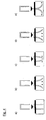
- the staple bar 10 off Fig. 1 has a plurality of interconnected clips 12.
- the brackets 12 are connected together by an adhesive.
- Each bracket 12 forms a U with a back 14 and two legs 16.
- the juxtaposed brackets 12 form the profile bar also U-shaped clamp rod 10.
- each 10 to 200 staples 12 can be combined to form a staple 10.
- the details of the individual brackets 12 are in the FIGS. 2 and 3 better recognizable.
- Fig. 2 shows a clamp 12 of a staple bar 10 according to the invention, which consists of a circular steel wire in cross-section.
- Fig. 2 a) shows a plan view from the side on one of the legs 16. In the plan view of Fig. 2 b) the view is directed to the plane of the bracket 12 so that both legs 16 and the back 14 of the bracket 12 are visible. In Fig. 2c) the view is directed from the side facing away from the back 14 on the free ends of the two legs 16.
- Fig. 2 d) shows an enlargement of the designated A section of the Fig. 2 b).
- Fig. 2 e) shows an enlargement of the designated B section of the Fig. 2c) ,
- the legs 16 each have a cylindrical portion 18 which is connected at one end to the back 14 of the bracket 12.
- the transition between the back 14 and the cylindrical portion 18 has a relatively small radius of curvature, which has arisen by bending the wire.
- the cylindrical portions 18 extend almost over the entire length of the legs 16.
- the free end of the legs 16 closes to the cylindrical portions 18 each one End section 20 at.
- Each leg 16 has a central longitudinal axis 22, which is shown in dashed lines.
- the central longitudinal axis 22 extends straight through the center of the cylindrical portion 18th
- the end portions 20 are tapered with increasing distance from the cylindrical portion 18 and converge pointedly in a arranged on the central longitudinal axis 22 point 24 together.
- a tip is formed, which may be more or less rounded.
- the end portion 20 is mirror-symmetrical to a second plane of symmetry 32 is formed.
- the second plane of symmetry 32 extends perpendicular to the plane of the drawing, ie, as it were perpendicular to the back 14 of the associated bracket 12, and includes the central longitudinal axis 22.
- the end portion 20 also has two first edges 26 and two second edges 36, between each of which inclined surfaces 28 are formed.
- the inclined surfaces are inclined relative to the central longitudinal axis 22 at an angle of approximately 30 °.
- the first two edges 26 lie in the first plane of symmetry 30, corresponding to the plane of the drawing Fig. 2 d)
- the two second edges 36 one of which faces the viewer, the other located on the back and therefore is not visible, lie in the second plane of symmetry 32.
- the first two edges 26 are opposite each other with respect to the central longitudinal axis 22. This also applies to the two second edges 36.
- the first edges 26 and the second edges 36 each begin at the point 24 and extend straight from there to the cylindrical portion 18.
- the end portions 20 are also also mirror-symmetrical relative to a first plane of symmetry 30, which includes the central longitudinal axes 22 of both legs 16.
- This first symmetry plane 30 is in the Fig. 2 a) perpendicular to the drawing plane.
- the two legs 16 are aligned parallel to each other, according to the two associated central longitudinal axes 22. Between the back 14 and the adjoining legs 16, a right angle is formed.
- the first symmetry plane 30 and the second symmetry plane 32 are drawn. Both are again perpendicular to the drawing plane. It can also be seen the four inclined surfaces 28, which are each arranged in pairs opposite one another, and the first edges 26 and second edges 36 extending therebetween.
- the point 24 of the end portion 20 is located in both the first plane of symmetry 30 and in the second Symmetrieebene 32 and also on the central longitudinal axis 22nd
- Fig. 3 be for the the embodiment of the Fig. 2 corresponding parts used the same reference numerals.
- the in the Fig. 3 shown bracket 12 differs from that of the Fig. 2 in that the circular wire used for the production is provided by rolling with two opposite flattenings 34. This is best in the Fig. 3 e) recognizable.
- the flats 34 extend over the entire length of the wire used for the production of the clip, ie they are formed both on the back 14 and on the legs 16 or at least on the cylindrical portions 18.
- the flats 34 are formed on the cylindrical portions 18 of the legs 16 parallel to the second plane of symmetry 32.
- the adjoining Cross-sectional portions of the cylindrical portions 18 are approximately semi-circular, but slightly deformed by the flattened rolls 34 with respect to ideal semi-circles.
- the end portions 20 of the bracket 12 off Fig. 3 are different from those Fig. 2 through the different cross section of the processed wire.
- the end portion 20 also has four with respect to the central longitudinal axis 22 inclined inclined surfaces 28. These are each bounded by two different edges 26, 36.
- the first edges 26 disposed in the first plane of symmetry 30 are shorter than the second edges 36 disposed in the second plane of symmetry 32. Since the first and second edges 26, 36 each include an equally large angle with the longitudinal axis 22, the different Length of the first and second edges 26, 36 due to the larger dimensions of the processed wire in the second plane of symmetry 32 in comparison to the dimensions in the first plane of symmetry 30. Nevertheless, the greater length of the second edges 36 can prevent a deflection of the legs 16 when driven into a material toward the center of the bracket 12 particularly effective.
Description
Die Erfindung betrifft einen Klammerstab mit einer Vielzahl von miteinander verbundenen Klammern zur Befestigung von Dämmplatten an Holzständern. Die Klammem derartiger Klammerstäbe weisen jeweils einen Rücken und zwei mit dem Rücken verbundene, parallel zueinander angeordnete Schenkel auf. Die Schenkel weisen jeweils einen zylindrischen Abschnitt und einen Endabschnitt auf.The invention relates to a staple bar with a plurality of interconnected brackets for fixing insulation boards to wooden stands. The Klammem such staple rods each have a back and two connected to the back, arranged parallel to each leg. The legs each have a cylindrical portion and an end portion.
Klammerstäbe sind bewährte Befestigungsmittel zur Verarbeitung mit Klammergeräten. Hierzu werden die Klammerstäbe in spezielle Aufnahmen der Klammergeräte eingesetzt. Das Klammergerät treibt die Klammern dann einzeln in das Werkstück ein, indem es jeweils eine vorderste Klammer eines eingesetzten Klammerstabs von dem Klammerstab löst und in das Werkstück eintreibt. Je nach Anwendungsgebiet weisen die Klammern ganz unterschiedliche Abmessungen und unterschiedlich geformte Endabschnitte auf. Die gebräuchlichen Klammeranschnitte werden anhand der
Teil d) der Figur zeigt eine Alternative, die ebenfalls zu einem Aufspreizen der Schenkel führt und für die Anmelderin durch das Patent
Alle Klammern der
Ebenfalls bekannt sind Klammern mit einem sogenannten Sägeanschnitt gemäß
Bei der Befestigung von Dämmplatten an Holzständern, insbesondere im Fertighausbau, entstehen aufgrund der großen Dicke der Dämmplatten und der geringen Breite der Holzständer besondere Schwierigkeiten. Zwar lassen sich die für die Befestigung benötigten, sehr langen Klammern trotz einer Dicke der Dämmplatten von beispielsweise 10 cm oder mehr leicht in die relativ nachgiebigen Dämmplatten eintreiben, jedoch nehmen die Schenkel der Klammer häufig keinen geradlinigen Verlauf durch die Dämmplatte hindurch. Stattdessen weichen die Schenkel so stark von dem angestrebten geradlinigen Verlauf ab, dass die an der Rückseite der Platte angeordneten Holzständer verfehlt werden. Eine ungenügende Befestigung ist die Folge.In the attachment of insulation boards to wooden stands, especially in prefabricated housing, arise due to the large thickness of the insulation boards and the small width of the wood stand special difficulties. Although the very long brackets required for fastening can be easily driven into the relatively resilient insulating panels despite a thickness of the insulating panels of, for example, 10 cm or more, however, the legs of the bracket often do not take a straight course through the insulating panel. Instead, the legs deviate so much from the desired rectilinear course, that the arranged on the back of the plate wooden stand are missed. An insufficient attachment is the result.
Aus der Druckschrift
Aus der Druckschrift
Aus der Druckschrift
Davon ausgehend ist es die Aufgabe der Erfindung, einen Klammerstab mit einer Vielzahl von miteinander verbundenen Klammern zur Befestigung von Dämmplatten an Holzständern zur Verfügung zu stellen, dessen Klammern geradliniger in die Dämmplatten eingetrieben werden können und so eine zuverlässige Befestigung auch von Dämmplatten großer Dicke an relativ schmalen Holzständern erlauben.On this basis, it is the object of the invention to provide a staple bar with a plurality of interconnected brackets for fixing insulation boards to wooden stands available, the brackets can be driven in a straight line in the insulation boards and so a reliable attachment of insulation boards of large thickness of relative allow narrow wooden stands.
Diese Aufgabe wird gelöst durch den Klammerstab mit den Merkmalen des Anspruchs 1. Vorteilhafte Ausgestaltungen sind in den Unteransprüchen angegeben. Der Klammerstab weist eine Vielzahl von miteinander verbundenen Klammern auf und dient zur Befestigung von Dämmplatten an Holzständern. Jede der Klammern weist einen Rücken und zwei mit dem Rücken verbundene, parallel zueinander angeordnete Schenkel auf. Die Länge der Schenkel ist mindestens dreimal so groß wie die Breite des Rückens. Jeder Schenkel weist einen zylindrischen Abschnitt und einen Endabschnitt auf. Der zylindrische Abschnitt hat einen über seine Länge gleichmäßigen Querschnitt, der zum Beispiel kreisförmig, aber auch oval, abgeflacht oder vieleckig sein kann. Bei der Erfindung verjüngt sich jeder Endabschnitt mit zunehmendem Abstand von dem zylindrischen Abschnitt und läuft spitz in einem auf einer Mittellängsachse des jeweiligen Schenkels angeordneten Punkt zusammen.This object is achieved by the staple bar having the features of
Die Erfindung beruht auf der Erkenntnis, dass herkömmliche Klammern mit einem Meißelanschnitt bei der Verwendung mit Dämmplatten nicht zum gewünschten Erfolg führen. Es wird vermutet, dass hierzu einerseits die besonderen Eigenschaften der Dämmplatten beitragen, denn diese bestehen in der Regel aus inhomogenen Werkstoffen wie z. B. wirr angeordneten Holzfasern. Außerdem wurde festgestellt, dass Meißelanschnitte insbesondere bei größeren Drahtstärken schwerlich mit perfekter Symmetrie gefertigt werden können. Stattdessen kommt es beim Herstellen der Meißelanschnitte mittels einer Stanze zu einem unsymmetrischen Stanzabriss, der zu einer seitlichen Ablenkung des Schenkels beim Eintreiben in die Dämmplatte führen kann.The invention is based on the finding that conventional staples with a chisel cutting when used with insulation boards do not lead to the desired success. It is believed that on the one hand contribute to the special properties of the insulation boards, because these are usually made of inhomogeneous materials such. B. confused wood fibers. In addition, it was found that chisel cuts can hardly be made with perfect symmetry, especially for larger wire sizes. Instead, it comes when making the chisel cuts by means of a punch to a single-ended punching tear, which can lead to a lateral deflection of the leg when driving into the insulation board.
Überraschend wurde beobachtet, dass die Herstellung geeigneter Klammern einfacher gelingt, wenn die Schenkel mit in einem Punkt auf der Mittellängsachse des jeweiligen Schenkels spitz zusammenlaufenden Endabschnitten gefertigt werden. Es wird vermutet, dass der beim Eintreiben beobachtete geradlinigere Verlauf von Klammern mit derartigen Endabschnitten einerseits darauf zurückzuführen ist, dass die annähernd punktförmig auslaufenden Spitzen weniger auf Materialinhomogenitäten der Dämmplatten ansprechen. Andererseits könnte zum Erfolg beitragen, dass bei der Fertigung derartiger Spitzen einfacher eine hinreichende Symmetrie des Endabschnitts erreicht werden kann.Surprisingly, it has been observed that the production of suitable staples is easier if the legs are manufactured with end sections converging at a point on the central longitudinal axis of the respective leg. On the one hand, it is believed that the more rectilinear course of staples with such end portions, observed during driving, is due to the fact that the approximately punctiform tips are less sensitive to material inhomogeneities to address the insulation boards. On the other hand, could contribute to the success that in the production of such peaks easier enough symmetry of the end portion can be achieved.
Die erfindungsgemäßen Klammerstäbe können insbesondere im eingangs skizzierten Eindrahtverfahren hergestellt werden. Die Endabschnitte können beim Trennen des Drahts in die jeweils für eine Klammer benötigten Längsabschnitte geformt werden. Anschließend können die Längsabschnitte durch zweimaliges Abkanten im 90°-Winkel in die endgültige Form der Klammern gebracht und miteinander verbunden werden, insbesondere über ein geeignetes Klebemittel.The staple bars according to the invention can be produced in particular in the above-outlined single-wire method. The end portions can be formed when separating the wire into the respective longitudinal sections required for a staple. Subsequently, the longitudinal sections can be brought into the final shape of the clips by folding twice at a 90 ° angle and connected to one another, in particular via a suitable adhesive.
Dass die Endabschnitte spitz in einem auf einer Mittellängsachse des jeweiligen Schenkels angeordneten Punkt zusammenlaufen, bedeutet nicht notwendigerweise, dass eine perfekt punktförmige Spitze vorhanden sein muss. Auch mehr oder weniger stark abgerundete oder infolge von Fertigungstoleranzen deformierte, nicht perfekt punktförmige Spitzen werden als spitz in einem Punkt zusammenlaufend angesehen.The fact that the end portions converge sharply in a point located on a central longitudinal axis of the respective leg does not necessarily mean that a perfectly point-like point must be present. Also, more or less rounded or deformed due to manufacturing tolerances, not perfectly point-like peaks are considered as converging point in a point.
Für die sonstige Formgebung der sich verjüngenden Endabschnitte gibt es unterschiedliche Möglichkeiten. Die Endabschnitte können beispielsweise konisch ausgebildet sein. Ebenfalls möglich ist die Verwendung sogenannter ballistischer Spitzen. Diese sind vergleichbar mit den Spitzen von Projektilen geformt, weisen also sich von dem zylindrischen Abschnitt zu der Spitze hin mit zunehmender Steigung verringernde Querschnittsabmessungen auf.For the other shape of the tapered end sections, there are different possibilities. The end portions may be conical, for example. Also possible is the use of so-called ballistic tips. These are shaped similar to the tips of projectiles, so have decreasing cross-sectional dimensions from the cylindrical portion to the tip with increasing pitch.
In einer Ausgestaltung sind die Endabschnitte einer Klammer spiegelsymmetrisch zu einer die Mittellängsachsen beider Schenkel dieser Klammer einschließenden ersten Symmetrieebene. Dadurch wird eine Ablenkung der Endabschnitte senkrecht zu der ersten Symmetrieebene verhindert.In one embodiment, the end sections of a clip are mirror-symmetrical to a first axis enclosing the central longitudinal axes of both legs of this clip Plane of symmetry. This prevents a deflection of the end sections perpendicular to the first plane of symmetry.
In einer Ausgestaltung ist der Endabschnitt eines Schenkels spiegelsymmetrisch zu einer zweiten Symmetrieebene, die die Mittellängsachse dieses Schenkels einschließt und senkrecht zu dem mit diesem Schenkel verbundenen Rücken angeordnet ist. Diese Maßnahme verhindert eine Ablenkung der Endabschnitte insbesondere senkrecht zu der zweiten Symmetrieebene. Ablenkungen in dieser Richtung sind besonders schwer zur kontrollieren, weil die Klammern in dieser Richtung bedingt durch das zweimalige Abkanten des Drahtes relativ große Fertigungstoleranzen aufweisen, denen ein an einem Klammergerät ausgebildeter Führungsmechanismus Rechnung tragen muss. Außerdem können einige einfache Klammergeräte die Schenkel während des Eintreibens an den einander zugewandten Innenseiten der beiden Schenkel nicht führen, weil in diesen Bereichen angeordnete Führungselemente beim Eintreiben der Klammer aus dem Weg des Klammerrückens entfernt werden müssen, um nicht mit diesem zu kollidieren, was eine relativ aufwendige Konstruktion der Führung erfordert. Es ist daher besonders vorteilhaft, der Ablenkung eines Schenkels zu dem jeweils anderen Schenkel der Klammer hin durch die genannte spiegelsymmetrische Gestaltung des Endabschnitts entgegenzuwirken.In one embodiment, the end portion of a leg is mirror-symmetrical to a second plane of symmetry, which includes the central longitudinal axis of this leg and is arranged perpendicular to the back connected to this leg. This measure prevents a deflection of the end sections, in particular perpendicular to the second plane of symmetry. Distractions in this direction are particularly difficult to control, because the brackets in this direction, due to the two-fold bending of the wire relatively large manufacturing tolerances, which must take into account a formed on a stapler guide mechanism. In addition, some simple staplers can not guide the legs during driving on the facing inner sides of the two legs, because arranged in these areas guide elements must be removed when driving the clip out of the way of the staple back, so as not to collide with this, which is a relative elaborate construction of the guide requires. It is therefore particularly advantageous to counteract the deflection of a leg to the respective other leg of the clip through the said mirror-symmetrical design of the end portion.
In einer Ausgestaltung weist der Endabschnitt im Querschnitt zwei erste Kanten auf, die in der ersten Symmetrieebene angeordnet sind. Die beiden ersten Kanten können insbesondere von dem die Spitze des Endabschnitts bildenden Punkt ausgehen. Sie können sich von dort aus bis zu dem zylindrischen Abschnitt hin erstrecken, zum Beispiel geradlinig. Die ersten Kanten wirken ähnlich wie Schneidkanten und bewirken eine Führung der Endabschnitte in Richtung der Mittellängsachse. Dadurch verhindern sie eine unerwünschte Ablenkung der Schenkel aus der ersten Symmetrieebene.In one embodiment, the end portion in cross section has two first edges, which are arranged in the first plane of symmetry. In particular, the two first edges can emanate from the point forming the tip of the end section. You can extend from there to the cylindrical section, for example straight. The first edges act similar to cutting edges and cause a guide of the end portions in the direction of the central longitudinal axis. As a result, they prevent unwanted deflection of the legs from the first plane of symmetry.
In einer Ausgestaltung weist der Endabschnitt im Querschnitt zwei zweite Kanten auf, die in der zweiten Symmetrieebene angeordnet sind. Die beiden zweiten Kanten können insbesondere von dem die Spitze des Endabschnitts bildenden Punkt ausgehen. Sie können sich von dort aus bis zu dem zylindrischen Abschnitt hin erstrecken, zum Beispiel geradlinig. Die zweiten Kanten wirken ebenfalls wie die ersten Kanten ähnlich wie Schneidkanten und bewirken eine Führung der Endabschnitte in Richtung der Mittellängsachse. Wegen ihrer Anordnung in der zweiten Symmetrieebene verhindern sie insbesondere eine unerwünschte Ablenkung der Schenkel aus dieser zweiten Symmetrieebene.In one embodiment, the end portion in cross-section two second edges, which are arranged in the second plane of symmetry. The two second edges may originate in particular from the point forming the tip of the end section. You can extend from there to the cylindrical section, for example straight. Like the first edges, the second edges also act similar to cutting edges and cause the end sections to be guided in the direction of the central longitudinal axis. Because of their arrangement in the second plane of symmetry they prevent in particular an undesirable deflection of the legs from this second plane of symmetry.
In einer Ausgestaltung sind die beiden ersten Kanten und/oder die beiden zweiten Kanten in einem Winkel im Bereich von 20° bis 60° zur Mittellängsachse angeordnet. In diesem Winkelbereich wird Versuchen zufolge eine vorteilhafte Führungswirkung erreicht.In one embodiment, the two first edges and / or the two second edges are arranged at an angle in the range of 20 ° to 60 ° to the central longitudinal axis. In this angular range, attempts are made to achieve an advantageous guiding effect.
In einer Ausgestaltung sind die beiden zweiten Kanten länger als die beiden ersten Kanten. Die unterschiedlichen Längen können durch längere Halbachsen des Querschnitts in der zweiten Symmetrieebene als in der ersten Symmetrieebene gebildet werden. Ebenfalls möglich ist, die zweiten Kanten in einem kleineren Winkel zu der Mittellängsachse auszubilden als die ersten Kanten. Durch diese Ausgestaltung wird insbesondere die Führung in der zweiten Symmetrieebene verbessert, die aus den geschilderten Gründen in der Praxis besonders wichtig ist.In one embodiment, the two second edges are longer than the first two edges. The different lengths can be formed by longer half-axes of the cross-section in the second plane of symmetry than in the first plane of symmetry. It is also possible to form the second edges at a smaller angle to the central longitudinal axis than the first edges. By this embodiment, in particular the guide is improved in the second plane of symmetry, which is particularly important for the described reasons in practice.
In einer Ausgestaltung weisen die Endabschnitte einen quadratischen oder rautenförmigen Querschnitt auf. Im Falle eines quadratischen Querschnitts können die Endabschnitte tetraedrisch sein, also die Form einer Pyramide mit quadratischer Grundfläche aufweisen. Derartige Spitzen werden auch als Diamantspitzen bezeichnet. Bei einem rautenförmigen Querschnitt sind an den vier Ecken des Querschnitts keine rechten Winkel ausgebildet, sondern die "Pyramide" hat eine rautenförmige Grundfläche mit vier gleichlangen Seiten. Derartige Endabschnitte mit rautenförmigem Querschnitt bieten sich insbesondere in Verbindung mit im Querschnitt ovalen oder abgeflachten Drähten an.In one embodiment, the end portions have a square or diamond-shaped cross-section. In the case of a square cross-section can the end sections to be tetrahedral, so have the shape of a pyramid with a square base. Such tips are also referred to as diamond tips. In a diamond-shaped cross-section, no right angles are formed at the four corners of the cross-section, but the "pyramid" has a diamond-shaped base with four equal sides. Such end portions with diamond-shaped cross-section are particularly suitable in connection with cross-sectionally oval or flattened wires.
Bei der Erfindung weist der Endabschnitt eines Schenkels mindestens eine Schrägfläche auf, die gegenüber der Mittellängsachse des Schenkels in einem Winkel im Bereich von 20° bis 60° geneigt ist. Endabschnitte mit derartigen Schrägflächen können einfach hergestellt werden, insbesondere mit speziellen Stanzwerkzeugen, und tragen zu einem geradlinigen Eindringen der Schenkel bei.In the invention, the end portion of a leg on at least one inclined surface which is inclined relative to the central longitudinal axis of the leg at an angle in the range of 20 ° to 60 °. End portions with such inclined surfaces can be easily manufactured, in particular with special punching tools, and contribute to a straight-line penetration of the legs.
In einer Ausgestaltung sind die Endabschnitte im Querschnitt oval oder kreisförmig. In diesem Fall können die Endabschnitte insgesamt insbesondere konisch oder abgeflacht-konisch sein. In beiden Fällen wird ein geradliniges Eindringen der Schenkel begünstigt.In one embodiment, the end portions are oval or circular in cross-section. In this case, the end portions may be in particular conical or flattened-conical overall. In both cases, a straight penetration of the legs is favored.
In einer Ausgestaltung sind die zylindrischen Abschnitte und/oder der Rücken im Querschnitt oval oder kreisförmig. Insbesondere können zur Herstellung der Klammern Drähte mit entsprechendem Querschnitt verwendet werden.In one embodiment, the cylindrical sections and / or the back are oval or circular in cross-section. In particular, wires with a corresponding cross-section can be used to produce the staples.
In einer Ausgestaltung sind die zylindrischen Abschnitte und/oder der Rücken aus einem im Querschnitt kreisförmigen Draht hergestellt, der durch Walzen mit zwei gegenüberliegenden Abflachungen versehen ist. Durch dieses Walzen des Drahtes können die Schenkel, insbesondere die zylindrischen Abschnitte, durch Ausbilden Auch diese Maßnahme trägt zu einem geradlinigen Eindringen der Schenkel in den Werkstoff bei.In one embodiment, the cylindrical portions and / or the back are made of a circular cross-section wire which is provided by rollers with two opposite flats. By this rolling of the wire, the legs, in particular the cylindrical sections, by forming This measure also contributes to a straight penetration of the legs in the material.
In einer Ausgestaltung weisen die zylindrischen Abschnitte und/oder die Rücken der Klammern einen Durchmesser im Bereich von 2 mm bis 4 mm auf. Bevorzugt kann der genannte Durchmesser im Bereich von 2,5 mm bis 3,5 mm liegen. Derartige Materialstärken erlauben die Herstellung auch sehr langer Klammern, die eine ausreichende Steifigkeit bei einer Schenkellänge im Bereich von beispielsweise 100 mm bis 220 mm, bevorzugt im Bereich von 160 mm bis 200 mm, aufweisen. Die Breite des Rückens derartiger Klammern kann beispielsweise im Bereich von 15 mm bis 35 mm, bevorzugt im Bereich von 20 mm bis 30 mm, liegen.In one embodiment, the cylindrical sections and / or the backs of the brackets have a diameter in the range of 2 mm to 4 mm. Preferably, said diameter may be in the range of 2.5 mm to 3.5 mm. Such material thicknesses allow the production of very long staples, which have sufficient rigidity at a leg length in the range of, for example, 100 mm to 220 mm, preferably in the range of 160 mm to 200 mm. The width of the back of such staples may be, for example, in the range of 15 mm to 35 mm, preferably in the range of 20 mm to 30 mm.
In einer Ausgestaltung sind die Klammern über ein Klebemittel miteinander verbunden. Das Klebemittel kann beispielsweise ein Lack oder ein Leim sein. Ebenfalls möglich, und zwar alternativ oder auch zusätzlich, ist die Verwendung von Klebestreifen, beispielsweise aus Papier oder aus einem elastischen Material.In one embodiment, the clips are connected together by an adhesive. The adhesive may be, for example, a varnish or a glue. Also possible, and alternatively or in addition, is the use of adhesive tape, for example made of paper or of an elastic material.
Die Erfindung wird nachfolgend anhand von in Figuren dargestellten Ausführungsbeispielen näher erläutert. Es zeigen:
- Fig. 1
- einen erfindungsgemäßen Klammerstab in einer vereinfachten, schematischen Darstellung,
- Fig. 2 a) - e)
- eine Klammer eines erfindungsgemäßen Klammerstabs in unterschiedlichen Ansichten,
- Fig. 3 a) - e)
- eine Klammer eines anderen erfindungsgemäßen Klammerstabs in unterschiedlichen Ansichten,
- Fig. 4 a) - e)
- fünf unterschiedliche Klammern gemäß dem Stand der Technik.
- Fig. 1
- a clamp rod according to the invention in a simplified, schematic representation,
- Fig. 2 a) - e)
- a bracket of a staple rod according to the invention in different views,
- Fig. 3 a) - e)
- a clip of another clip stick according to the invention in different views,
- Fig. 4 a) - e)
- five different brackets according to the prior art.
Der Klammerstab 10 aus
In den
Wie am besten in der
Wie in der
Der Endabschnitt 20 weist außerdem zwei erste Kanten 26 und zwei zweite Kanten 36 auf, zwischen denen jeweils Schrägflächen 28 ausgebildet sind. Die Schrägflächen sind gegenüber der Mittellängsachse 22 in einem Winkel von ungefähr 30° geneigt. Die beiden ersten Kanten 26 liegen in der ersten Symmetrieebene 30, entsprechend der Zeichenebene der
Wie in der
Die beiden Schenkel 16 sind parallel zueinander ausgerichtet, entsprechend auch die beiden zugehörigen Mittellängsachsen 22. Zwischen dem Rücken 14 und den sich daran anschließenden Schenkeln 16 ist ein rechter Winkel ausgebildet.The two
In der
In der
Die Endabschnitte 20 der Klammer 12 aus
Die
Claims (13)
- A staple strip (10) having a plurality of staples (12) connected to each other, for fastening insulating panels to wooden supports, wherein• each of the staples (12) has a crown (14) and two legs (16), disposed parallel to each other and connected to the crown (14),• the length of the legs (16) is at least three times as long as the width of the crown (14), and• each leg (16) has a cylindrical section (18) and an end section (20), characterized in that• each end section (20) tapers with increasing distance from the cylindrical section (18), and tapers to a point (24) disposed on a center longitudinal axis (22) of the respective leg (16), wherein• the end section (20) of a leg (16) has at least one angled face (28) which is inclined at an angle in the range of 20° to 60° with respect to the center longitudinal axis (22) of the leg (16).
- The staple strip (10) according to claim 1, characterized in that the end sections (20) of a staple (12) are mirror symmetrical to a first plane of symmetry (30) enclosing the center longitudinal axis (22) of both legs (16) of the staple (12).
- The staple strip (10) according to one of the claims 1 or 2, characterized in that the end section (20) of a leg (16) is mirror symmetrical to a second plane of symmetry (32) which encloses the center longitudinal axis (22) of this leg (16), and is disposed perpendicular to the crown (14) connected to this leg (16).
- The staple strip (10) according to one of the claims 2 or 3, characterized in that the end section (20) has two first edges (26) which are disposed in the first plane of symmetry (30).
- The staple strip (10) according to one of the claims 3 or 4, characterized in that the end section (20) has two second edges (36) which are disposed in the second plane of symmetry (32).
- The staple strip (10) according to one of the claims 4 or 5, characterized in that the two first edges (26) and/or the two second edges (36) are disposed at an angle in the range of 20° to 60° with respect to the center longitudinal axis (22).
- The staple strip (10) according to one of the claims 5 or 6, characterized in that the two second edges (36) are longer than the two first edges (26).
- The staple strip (10) according to one of the claims 1 to 7, characterized in that the end sections (20) have a square or diamond shaped cross-section.
- The staple strip (10) according to one of claims 1 to 3, characterized in that the end sections (20) have an oval or circular cross-section.
- The staple strip (10) according to one of claims 1 to 9, characterized in that the cylindrical sections (18) and/or the crown (14) have an oval or circular cross-section.
- The staple strip (10) according to one of the claims 1 to 10, characterized in that the cylindrical sections (18) and/or the crown (14) are produced from a wire having a circular cross-section that is provided with two flattenings (34) lying across from each other, using rolling.
- The staple strip (10) according to one of the claims 1 to 11, characterized in that the cylindrical sections (18) and/or the crown (14) of the staple (12) have a diameter in the range of 2 mm to 4 mm.
- The staple strip (10) according to one of claims 1 to 12, characterized in that the staples (12) are connected together using an adhesive means.
Priority Applications (7)
| Application Number | Priority Date | Filing Date | Title |
|---|---|---|---|
| ES12002061.5T ES2480296T3 (en) | 2012-03-23 | 2012-03-23 | Staple strip for fixing insulation plates to wooden uprights |
| EP12002061.5A EP2642137B1 (en) | 2012-03-23 | 2012-03-23 | Clip row for fixing insulation boards to wooden stands |
| PL12002061T PL2642137T3 (en) | 2012-03-23 | 2012-03-23 | Clip row for fixing insulation boards to wooden stands |
| DE202012009301U DE202012009301U1 (en) | 2012-03-23 | 2012-03-23 | Clip rod for fixing insulation boards to wooden posts |
| CA2807291A CA2807291C (en) | 2012-03-23 | 2013-02-26 | Staple strip for fastening insulating panels to wooden supports |
| RU2013111681/12A RU2563220C2 (en) | 2012-03-23 | 2013-03-18 | Bracket unit |
| US13/848,824 US8956097B2 (en) | 2012-03-23 | 2013-03-22 | Staple strip for fastening insulating panels to wooden supports |
Applications Claiming Priority (1)
| Application Number | Priority Date | Filing Date | Title |
|---|---|---|---|
| EP12002061.5A EP2642137B1 (en) | 2012-03-23 | 2012-03-23 | Clip row for fixing insulation boards to wooden stands |
Publications (2)
| Publication Number | Publication Date |
|---|---|
| EP2642137A1 EP2642137A1 (en) | 2013-09-25 |
| EP2642137B1 true EP2642137B1 (en) | 2014-04-23 |
Family
ID=49230954
Family Applications (1)
| Application Number | Title | Priority Date | Filing Date |
|---|---|---|---|
| EP12002061.5A Revoked EP2642137B1 (en) | 2012-03-23 | 2012-03-23 | Clip row for fixing insulation boards to wooden stands |
Country Status (7)
| Country | Link |
|---|---|
| US (1) | US8956097B2 (en) |
| EP (1) | EP2642137B1 (en) |
| CA (1) | CA2807291C (en) |
| DE (1) | DE202012009301U1 (en) |
| ES (1) | ES2480296T3 (en) |
| PL (1) | PL2642137T3 (en) |
| RU (1) | RU2563220C2 (en) |
Cited By (1)
| Publication number | Priority date | Publication date | Assignee | Title |
|---|---|---|---|---|
| DE102017100748A1 (en) | 2017-01-16 | 2018-07-19 | Raimund Beck Nageltechnik Gmbh | Method for producing a composite nail with low thermal conductivity |
Families Citing this family (7)
| Publication number | Priority date | Publication date | Assignee | Title |
|---|---|---|---|---|
| DE102013011804B4 (en) | 2013-07-16 | 2016-05-19 | Baussmann Collated Fasteners Gmbh | clamp rod |
| DE202013006362U1 (en) | 2013-07-16 | 2013-08-02 | Baussmann Collated Fasteners Gmbh | clamp rod |
| DE202014000807U1 (en) | 2014-01-31 | 2014-03-06 | Baussmann Collated Fasteners Gmbh | clamp rod |
| DE102014001153A1 (en) | 2014-01-31 | 2015-08-06 | Baussmann Collated Fasteners Gmbh | clamp rod |
| WO2018009682A1 (en) | 2016-07-07 | 2018-01-11 | Knauf Insulation, Inc. | Insulative material and method for installation |
| DE102018121065A1 (en) * | 2018-08-29 | 2020-03-05 | Baussmann Collated Fasteners Gmbh | Fastening element made of wood and / or wood materials as well as a holding belt with fastening elements for an energy-operated setting tool |
| USD988856S1 (en) * | 2022-10-06 | 2023-06-13 | Coastal Source, LLC | Cable staple |
Family Cites Families (16)
| Publication number | Priority date | Publication date | Assignee | Title |
|---|---|---|---|---|
| US1939631A (en) * | 1932-09-01 | 1933-12-12 | Randall Company | Staple blank or strip and method of making same |
| US1998991A (en) * | 1935-01-23 | 1935-04-23 | J C Ulmer Company | Method of making sheet metal staples |
| US3128667A (en) * | 1959-11-19 | 1964-04-14 | United Shoe Machinery Corp | Staple having a leg configuration for securing wood or metal studding |
| US3403592A (en) * | 1966-11-07 | 1968-10-01 | Larson Co Charles O | Staple structure |
| DE1956332U (en) * | 1966-12-16 | 1967-03-02 | Elastic G M B H | U-SHAPED CURVED STAPLES. |
| US3813985A (en) * | 1969-07-30 | 1974-06-04 | Spotnails | Fasteners and method of manufacture thereof |
| US4114859A (en) * | 1977-02-03 | 1978-09-19 | Stenson Stanley E | Fence staple |
| US5223675A (en) * | 1992-04-02 | 1993-06-29 | Taft Anthony W | Cable fastener |
| US5441373A (en) * | 1993-09-07 | 1995-08-15 | Illinois Tool Works Inc. | Coated fastener |
| US5772379A (en) * | 1996-05-24 | 1998-06-30 | Evensen; Kenneth | Self-filling staple fastener |
| DE29903556U1 (en) * | 1999-02-27 | 1999-05-27 | Haubold Kihlberg Gmbh | Fastening element for wood wool lightweight panels |
| NL1015623C1 (en) * | 1999-11-02 | 2001-05-03 | Rob R Hermanus Wilhelmus Koend | Device for securing an object. |
| US6305891B1 (en) * | 2000-05-15 | 2001-10-23 | Mark S. Burlingame | Fastening device and a spacer, and a method of using the same |
| DE10203282A1 (en) | 2002-01-29 | 2003-08-21 | Behrens Ag Friedrich Joh | Fasteners and process for its manufacture |
| US7581911B2 (en) * | 2002-09-18 | 2009-09-01 | Utility Composites International Limited | Plastic impact driven fasteners |
| US20090191023A1 (en) * | 2008-01-28 | 2009-07-30 | Hsueh-Pin Chang | Nail strip of u-shaped nails |
-
2012
- 2012-03-23 PL PL12002061T patent/PL2642137T3/en unknown
- 2012-03-23 DE DE202012009301U patent/DE202012009301U1/en not_active Expired - Lifetime
- 2012-03-23 ES ES12002061.5T patent/ES2480296T3/en active Active
- 2012-03-23 EP EP12002061.5A patent/EP2642137B1/en not_active Revoked
-
2013
- 2013-02-26 CA CA2807291A patent/CA2807291C/en not_active Expired - Fee Related
- 2013-03-18 RU RU2013111681/12A patent/RU2563220C2/en not_active IP Right Cessation
- 2013-03-22 US US13/848,824 patent/US8956097B2/en not_active Expired - Fee Related
Cited By (2)
| Publication number | Priority date | Publication date | Assignee | Title |
|---|---|---|---|---|
| DE102017100748A1 (en) | 2017-01-16 | 2018-07-19 | Raimund Beck Nageltechnik Gmbh | Method for producing a composite nail with low thermal conductivity |
| DE102017100748B4 (en) | 2017-01-16 | 2024-01-18 | Raimund Beck Nageltechnik Gmbh | Method for driving a nail into a substrate |
Also Published As
| Publication number | Publication date |
|---|---|
| CA2807291C (en) | 2018-03-13 |
| US8956097B2 (en) | 2015-02-17 |
| RU2563220C2 (en) | 2015-09-20 |
| US20130251477A1 (en) | 2013-09-26 |
| DE202012009301U1 (en) | 2012-12-05 |
| CA2807291A1 (en) | 2013-09-23 |
| EP2642137A1 (en) | 2013-09-25 |
| PL2642137T3 (en) | 2014-09-30 |
| RU2013111681A (en) | 2014-09-27 |
| ES2480296T3 (en) | 2014-07-25 |
Similar Documents
| Publication | Publication Date | Title |
|---|---|---|
| EP2642137B1 (en) | Clip row for fixing insulation boards to wooden stands | |
| EP0274085B1 (en) | Plastic paper clip | |
| DE2100204B2 (en) | DEVICE FOR MANUFACTURING SELF-TAPPING SCREWS BY ROLLING A THREAD INTO A BLANK | |
| DE202013006362U1 (en) | clamp rod | |
| DE102013011804B4 (en) | clamp rod | |
| DE2206973C3 (en) | Spatial building element for the formation of load-bearing structures | |
| AT510711B1 (en) | BENDING TOOL AND BENDING TOOL ASSEMBLY | |
| DE2923903C2 (en) | ||
| DE2432192C3 (en) | Staple, and the composite product made with it | |
| DE1156280B (en) | Interconnects | |
| DE10015367C1 (en) | Pipe cutting machine | |
| DE3409151C1 (en) | Method and apparatus for the production of self-supporting constructional elements and the use of the same for covering annular-segment-shaped surfaces | |
| EP2759719B1 (en) | Holder for mounting pipes on a support | |
| DE202011108692U1 (en) | Hollow profile and hall frame with such a profile | |
| DE202014000807U1 (en) | clamp rod | |
| DE2614023A1 (en) | Tubular metal frame with easily formed curved corners - has incisions at curvature point forming smooth exterior when bent | |
| DE4434658C2 (en) | Insulation board and method for manufacturing an insulation board | |
| EP2615223B1 (en) | Device for covering the edges of coatings | |
| DE2619748C2 (en) | With the help of the roller pressing process produced connection of wooden rods and a roller pressing machine for producing the connection | |
| DE102015121334A1 (en) | Connector for double bar mesh mats | |
| CH712763A2 (en) | Method for producing a clamping jaw and a correspondingly produced clamping jaw. | |
| DE2128553B2 (en) | Arrangement for attaching a coupling piece for concrete formwork | |
| DE2004149C3 (en) | Formwork tie rod made of steel strip with a hollow plug-on cone | |
| DE2741533C2 (en) | Claw plate intended for joining wooden components | |
| DE202023105538U1 (en) | Fastening device for fastening at least one component, in particular at least one support element of photovoltaic and/or solar thermal modules, to an inclined roof, and use of such a fastening device |
Legal Events
| Date | Code | Title | Description |
|---|---|---|---|
| PUAI | Public reference made under article 153(3) epc to a published international application that has entered the european phase |
Free format text: ORIGINAL CODE: 0009012 |
|
| 17P | Request for examination filed |
Effective date: 20130416 |
|
| AK | Designated contracting states |
Kind code of ref document: A1 Designated state(s): AL AT BE BG CH CY CZ DE DK EE ES FI FR GB GR HR HU IE IS IT LI LT LU LV MC MK MT NL NO PL PT RO RS SE SI SK SM TR |
|
| AX | Request for extension of the european patent |
Extension state: BA ME |
|
| GRAP | Despatch of communication of intention to grant a patent |
Free format text: ORIGINAL CODE: EPIDOSNIGR1 |
|
| INTG | Intention to grant announced |
Effective date: 20131122 |
|
| GRAS | Grant fee paid |
Free format text: ORIGINAL CODE: EPIDOSNIGR3 |
|
| GRAA | (expected) grant |
Free format text: ORIGINAL CODE: 0009210 |
|
| AK | Designated contracting states |
Kind code of ref document: B1 Designated state(s): AL AT BE BG CH CY CZ DE DK EE ES FI FR GB GR HR HU IE IS IT LI LT LU LV MC MK MT NL NO PL PT RO RS SE SI SK SM TR |
|
| REG | Reference to a national code |
Ref country code: GB Ref legal event code: FG4D Free format text: NOT ENGLISH |
|
| REG | Reference to a national code |
Ref country code: CH Ref legal event code: EP |
|
| REG | Reference to a national code |
Ref country code: AT Ref legal event code: REF Ref document number: 664038 Country of ref document: AT Kind code of ref document: T Effective date: 20140515 |
|
| REG | Reference to a national code |
Ref country code: IE Ref legal event code: FG4D Free format text: LANGUAGE OF EP DOCUMENT: GERMAN |
|
| REG | Reference to a national code |
Ref country code: DE Ref legal event code: R096 Ref document number: 502012000608 Country of ref document: DE Effective date: 20140528 |
|
| REG | Reference to a national code |
Ref country code: CH Ref legal event code: NV Representative=s name: FIAMMENGHI-FIAMMENGHI, CH |
|
| REG | Reference to a national code |
Ref country code: NL Ref legal event code: T3 |
|
| REG | Reference to a national code |
Ref country code: ES Ref legal event code: FG2A Ref document number: 2480296 Country of ref document: ES Kind code of ref document: T3 Effective date: 20140725 |
|
| REG | Reference to a national code |
Ref country code: SE Ref legal event code: TRGR |
|
| REG | Reference to a national code |
Ref country code: NO Ref legal event code: T2 Effective date: 20140423 |
|
| REG | Reference to a national code |
Ref country code: LT Ref legal event code: MG4D |
|
| REG | Reference to a national code |
Ref country code: PL Ref legal event code: T3 |
|
| PG25 | Lapsed in a contracting state [announced via postgrant information from national office to epo] |
Ref country code: CY Free format text: LAPSE BECAUSE OF FAILURE TO SUBMIT A TRANSLATION OF THE DESCRIPTION OR TO PAY THE FEE WITHIN THE PRESCRIBED TIME-LIMIT Effective date: 20140423 Ref country code: BG Free format text: LAPSE BECAUSE OF FAILURE TO SUBMIT A TRANSLATION OF THE DESCRIPTION OR TO PAY THE FEE WITHIN THE PRESCRIBED TIME-LIMIT Effective date: 20140723 Ref country code: IS Free format text: LAPSE BECAUSE OF FAILURE TO SUBMIT A TRANSLATION OF THE DESCRIPTION OR TO PAY THE FEE WITHIN THE PRESCRIBED TIME-LIMIT Effective date: 20140823 Ref country code: GR Free format text: LAPSE BECAUSE OF FAILURE TO SUBMIT A TRANSLATION OF THE DESCRIPTION OR TO PAY THE FEE WITHIN THE PRESCRIBED TIME-LIMIT Effective date: 20140724 Ref country code: LT Free format text: LAPSE BECAUSE OF FAILURE TO SUBMIT A TRANSLATION OF THE DESCRIPTION OR TO PAY THE FEE WITHIN THE PRESCRIBED TIME-LIMIT Effective date: 20140423 |
|
| REG | Reference to a national code |
Ref country code: SK Ref legal event code: T3 Ref document number: E 16852 Country of ref document: SK |
|
| PG25 | Lapsed in a contracting state [announced via postgrant information from national office to epo] |
Ref country code: RS Free format text: LAPSE BECAUSE OF FAILURE TO SUBMIT A TRANSLATION OF THE DESCRIPTION OR TO PAY THE FEE WITHIN THE PRESCRIBED TIME-LIMIT Effective date: 20140423 Ref country code: LV Free format text: LAPSE BECAUSE OF FAILURE TO SUBMIT A TRANSLATION OF THE DESCRIPTION OR TO PAY THE FEE WITHIN THE PRESCRIBED TIME-LIMIT Effective date: 20140423 Ref country code: HR Free format text: LAPSE BECAUSE OF FAILURE TO SUBMIT A TRANSLATION OF THE DESCRIPTION OR TO PAY THE FEE WITHIN THE PRESCRIBED TIME-LIMIT Effective date: 20140423 |
|
| PG25 | Lapsed in a contracting state [announced via postgrant information from national office to epo] |
Ref country code: PT Free format text: LAPSE BECAUSE OF FAILURE TO SUBMIT A TRANSLATION OF THE DESCRIPTION OR TO PAY THE FEE WITHIN THE PRESCRIBED TIME-LIMIT Effective date: 20140825 |
|
| REG | Reference to a national code |
Ref country code: DE Ref legal event code: R026 Ref document number: 502012000608 Country of ref document: DE |
|
| PG25 | Lapsed in a contracting state [announced via postgrant information from national office to epo] |
Ref country code: DK Free format text: LAPSE BECAUSE OF FAILURE TO SUBMIT A TRANSLATION OF THE DESCRIPTION OR TO PAY THE FEE WITHIN THE PRESCRIBED TIME-LIMIT Effective date: 20140423 Ref country code: EE Free format text: LAPSE BECAUSE OF FAILURE TO SUBMIT A TRANSLATION OF THE DESCRIPTION OR TO PAY THE FEE WITHIN THE PRESCRIBED TIME-LIMIT Effective date: 20140423 Ref country code: RO Free format text: LAPSE BECAUSE OF FAILURE TO SUBMIT A TRANSLATION OF THE DESCRIPTION OR TO PAY THE FEE WITHIN THE PRESCRIBED TIME-LIMIT Effective date: 20140423 |
|
| PLBI | Opposition filed |
Free format text: ORIGINAL CODE: 0009260 |
|
| 26 | Opposition filed |
Opponent name: BAUSSMANN COLLATED FASTENERS GMBH Effective date: 20150121 |
|
| PLAX | Notice of opposition and request to file observation + time limit sent |
Free format text: ORIGINAL CODE: EPIDOSNOBS2 |
|
| REG | Reference to a national code |
Ref country code: DE Ref legal event code: R026 Ref document number: 502012000608 Country of ref document: DE Effective date: 20150121 |
|
| PLBB | Reply of patent proprietor to notice(s) of opposition received |
Free format text: ORIGINAL CODE: EPIDOSNOBS3 |
|
| PG25 | Lapsed in a contracting state [announced via postgrant information from national office to epo] |
Ref country code: SI Free format text: LAPSE BECAUSE OF FAILURE TO SUBMIT A TRANSLATION OF THE DESCRIPTION OR TO PAY THE FEE WITHIN THE PRESCRIBED TIME-LIMIT Effective date: 20140423 |
|
| PG25 | Lapsed in a contracting state [announced via postgrant information from national office to epo] |
Ref country code: LU Free format text: LAPSE BECAUSE OF FAILURE TO SUBMIT A TRANSLATION OF THE DESCRIPTION OR TO PAY THE FEE WITHIN THE PRESCRIBED TIME-LIMIT Effective date: 20150323 Ref country code: MC Free format text: LAPSE BECAUSE OF FAILURE TO SUBMIT A TRANSLATION OF THE DESCRIPTION OR TO PAY THE FEE WITHIN THE PRESCRIBED TIME-LIMIT Effective date: 20140423 |
|
| REG | Reference to a national code |
Ref country code: IE Ref legal event code: MM4A |
|
| PG25 | Lapsed in a contracting state [announced via postgrant information from national office to epo] |
Ref country code: IE Free format text: LAPSE BECAUSE OF NON-PAYMENT OF DUE FEES Effective date: 20150323 |
|
| REG | Reference to a national code |
Ref country code: FR Ref legal event code: PLFP Year of fee payment: 5 |
|
| PG25 | Lapsed in a contracting state [announced via postgrant information from national office to epo] |
Ref country code: MT Free format text: LAPSE BECAUSE OF FAILURE TO SUBMIT A TRANSLATION OF THE DESCRIPTION OR TO PAY THE FEE WITHIN THE PRESCRIBED TIME-LIMIT Effective date: 20140423 |
|
| RDAF | Communication despatched that patent is revoked |
Free format text: ORIGINAL CODE: EPIDOSNREV1 |
|
| STAA | Information on the status of an ep patent application or granted ep patent |
Free format text: STATUS: THE PATENT HAS BEEN GRANTED |
|
| APBM | Appeal reference recorded |
Free format text: ORIGINAL CODE: EPIDOSNREFNO |
|
| APBP | Date of receipt of notice of appeal recorded |
Free format text: ORIGINAL CODE: EPIDOSNNOA2O |
|
| APAH | Appeal reference modified |
Free format text: ORIGINAL CODE: EPIDOSCREFNO |
|
| REG | Reference to a national code |
Ref country code: FR Ref legal event code: PLFP Year of fee payment: 6 |
|
| APBQ | Date of receipt of statement of grounds of appeal recorded |
Free format text: ORIGINAL CODE: EPIDOSNNOA3O |
|
| PG25 | Lapsed in a contracting state [announced via postgrant information from national office to epo] |
Ref country code: SM Free format text: LAPSE BECAUSE OF FAILURE TO SUBMIT A TRANSLATION OF THE DESCRIPTION OR TO PAY THE FEE WITHIN THE PRESCRIBED TIME-LIMIT Effective date: 20140423 Ref country code: HU Free format text: LAPSE BECAUSE OF FAILURE TO SUBMIT A TRANSLATION OF THE DESCRIPTION OR TO PAY THE FEE WITHIN THE PRESCRIBED TIME-LIMIT; INVALID AB INITIO Effective date: 20120323 |
|
| PG25 | Lapsed in a contracting state [announced via postgrant information from national office to epo] |
Ref country code: BE Free format text: LAPSE BECAUSE OF NON-PAYMENT OF DUE FEES Effective date: 20150331 |
|
| REG | Reference to a national code |
Ref country code: FR Ref legal event code: PLFP Year of fee payment: 7 |
|
| PG25 | Lapsed in a contracting state [announced via postgrant information from national office to epo] |
Ref country code: MK Free format text: LAPSE BECAUSE OF FAILURE TO SUBMIT A TRANSLATION OF THE DESCRIPTION OR TO PAY THE FEE WITHIN THE PRESCRIBED TIME-LIMIT Effective date: 20140423 |
|
| PG25 | Lapsed in a contracting state [announced via postgrant information from national office to epo] |
Ref country code: AL Free format text: LAPSE BECAUSE OF FAILURE TO SUBMIT A TRANSLATION OF THE DESCRIPTION OR TO PAY THE FEE WITHIN THE PRESCRIBED TIME-LIMIT Effective date: 20140423 |
|
| PGFP | Annual fee paid to national office [announced via postgrant information from national office to epo] |
Ref country code: CZ Payment date: 20190319 Year of fee payment: 8 Ref country code: NO Payment date: 20190321 Year of fee payment: 8 Ref country code: CH Payment date: 20190325 Year of fee payment: 8 Ref country code: GB Payment date: 20190325 Year of fee payment: 8 Ref country code: FI Payment date: 20190319 Year of fee payment: 8 Ref country code: FR Payment date: 20190326 Year of fee payment: 8 Ref country code: IT Payment date: 20190321 Year of fee payment: 8 Ref country code: PL Payment date: 20190205 Year of fee payment: 8 |
|
| PGFP | Annual fee paid to national office [announced via postgrant information from national office to epo] |
Ref country code: TR Payment date: 20190314 Year of fee payment: 8 Ref country code: AT Payment date: 20190319 Year of fee payment: 8 Ref country code: NL Payment date: 20190321 Year of fee payment: 8 Ref country code: SE Payment date: 20190325 Year of fee payment: 8 |
|
| PGFP | Annual fee paid to national office [announced via postgrant information from national office to epo] |
Ref country code: SK Payment date: 20190118 Year of fee payment: 8 |
|
| PGFP | Annual fee paid to national office [announced via postgrant information from national office to epo] |
Ref country code: DE Payment date: 20190514 Year of fee payment: 8 Ref country code: ES Payment date: 20190424 Year of fee payment: 8 |
|
| APBU | Appeal procedure closed |
Free format text: ORIGINAL CODE: EPIDOSNNOA9O |
|
| REG | Reference to a national code |
Ref country code: DE Ref legal event code: R064 Ref document number: 502012000608 Country of ref document: DE Ref country code: DE Ref legal event code: R103 Ref document number: 502012000608 Country of ref document: DE |
|
| RDAG | Patent revoked |
Free format text: ORIGINAL CODE: 0009271 |
|
| STAA | Information on the status of an ep patent application or granted ep patent |
Free format text: STATUS: PATENT REVOKED |
|
| REG | Reference to a national code |
Ref country code: CH Ref legal event code: PL |
|
| REG | Reference to a national code |
Ref country code: FI Ref legal event code: MGE |
|
| 27W | Patent revoked |
Effective date: 20200204 |
|
| GBPR | Gb: patent revoked under art. 102 of the ep convention designating the uk as contracting state |
Effective date: 20200204 |
|
| REG | Reference to a national code |
Ref country code: SK Ref legal event code: MC4A Ref document number: E 16852 Country of ref document: SK Effective date: 20200204 |
|
| REG | Reference to a national code |
Ref country code: AT Ref legal event code: MA03 Ref document number: 664038 Country of ref document: AT Kind code of ref document: T Effective date: 20200204 |
|
| REG | Reference to a national code |
Ref country code: NO Ref legal event code: MMEP |