EP2893099B1 - Deckensystem - Google Patents
Deckensystem Download PDFInfo
- Publication number
- EP2893099B1 EP2893099B1 EP13762676.8A EP13762676A EP2893099B1 EP 2893099 B1 EP2893099 B1 EP 2893099B1 EP 13762676 A EP13762676 A EP 13762676A EP 2893099 B1 EP2893099 B1 EP 2893099B1
- Authority
- EP
- European Patent Office
- Prior art keywords
- support
- ceiling
- grid
- ceiling tile
- tegular
- Prior art date
- Legal status (The legal status is an assumption and is not a legal conclusion. Google has not performed a legal analysis and makes no representation as to the accuracy of the status listed.)
- Active
Links
Images


Classifications
-
- E—FIXED CONSTRUCTIONS
- E04—BUILDING
- E04B—GENERAL BUILDING CONSTRUCTIONS; WALLS, e.g. PARTITIONS; ROOFS; FLOORS; CEILINGS; INSULATION OR OTHER PROTECTION OF BUILDINGS
- E04B9/00—Ceilings; Construction of ceilings, e.g. false ceilings; Ceiling construction with regard to insulation
- E04B9/06—Ceilings; Construction of ceilings, e.g. false ceilings; Ceiling construction with regard to insulation characterised by constructional features of the supporting construction, e.g. cross section or material of framework members
- E04B9/10—Connections between parallel members of the supporting construction
-
- E—FIXED CONSTRUCTIONS
- E04—BUILDING
- E04B—GENERAL BUILDING CONSTRUCTIONS; WALLS, e.g. PARTITIONS; ROOFS; FLOORS; CEILINGS; INSULATION OR OTHER PROTECTION OF BUILDINGS
- E04B9/00—Ceilings; Construction of ceilings, e.g. false ceilings; Ceiling construction with regard to insulation
- E04B9/04—Ceilings; Construction of ceilings, e.g. false ceilings; Ceiling construction with regard to insulation comprising slabs, panels, sheets or the like
- E04B9/0435—Ceilings; Construction of ceilings, e.g. false ceilings; Ceiling construction with regard to insulation comprising slabs, panels, sheets or the like having connection means at the edges
-
- E—FIXED CONSTRUCTIONS
- E04—BUILDING
- E04B—GENERAL BUILDING CONSTRUCTIONS; WALLS, e.g. PARTITIONS; ROOFS; FLOORS; CEILINGS; INSULATION OR OTHER PROTECTION OF BUILDINGS
- E04B9/00—Ceilings; Construction of ceilings, e.g. false ceilings; Ceiling construction with regard to insulation
- E04B9/04—Ceilings; Construction of ceilings, e.g. false ceilings; Ceiling construction with regard to insulation comprising slabs, panels, sheets or the like
- E04B9/0464—Ceilings; Construction of ceilings, e.g. false ceilings; Ceiling construction with regard to insulation comprising slabs, panels, sheets or the like having irregularities on the faces, e.g. holes, grooves
-
- E—FIXED CONSTRUCTIONS
- E04—BUILDING
- E04B—GENERAL BUILDING CONSTRUCTIONS; WALLS, e.g. PARTITIONS; ROOFS; FLOORS; CEILINGS; INSULATION OR OTHER PROTECTION OF BUILDINGS
- E04B9/00—Ceilings; Construction of ceilings, e.g. false ceilings; Ceiling construction with regard to insulation
- E04B9/06—Ceilings; Construction of ceilings, e.g. false ceilings; Ceiling construction with regard to insulation characterised by constructional features of the supporting construction, e.g. cross section or material of framework members
- E04B9/065—Ceilings; Construction of ceilings, e.g. false ceilings; Ceiling construction with regard to insulation characterised by constructional features of the supporting construction, e.g. cross section or material of framework members comprising supporting beams having a folded cross-section
- E04B9/067—Ceilings; Construction of ceilings, e.g. false ceilings; Ceiling construction with regard to insulation characterised by constructional features of the supporting construction, e.g. cross section or material of framework members comprising supporting beams having a folded cross-section with inverted T-shaped cross-section
-
- E—FIXED CONSTRUCTIONS
- E04—BUILDING
- E04B—GENERAL BUILDING CONSTRUCTIONS; WALLS, e.g. PARTITIONS; ROOFS; FLOORS; CEILINGS; INSULATION OR OTHER PROTECTION OF BUILDINGS
- E04B9/00—Ceilings; Construction of ceilings, e.g. false ceilings; Ceiling construction with regard to insulation
- E04B9/22—Connection of slabs, panels, sheets or the like to the supporting construction
- E04B9/225—Connection of slabs, panels, sheets or the like to the supporting construction with the slabs, panels, sheets or the like hanging at a distance below the supporting construction
-
- E—FIXED CONSTRUCTIONS
- E04—BUILDING
- E04B—GENERAL BUILDING CONSTRUCTIONS; WALLS, e.g. PARTITIONS; ROOFS; FLOORS; CEILINGS; INSULATION OR OTHER PROTECTION OF BUILDINGS
- E04B9/00—Ceilings; Construction of ceilings, e.g. false ceilings; Ceiling construction with regard to insulation
- E04B9/22—Connection of slabs, panels, sheets or the like to the supporting construction
- E04B9/24—Connection of slabs, panels, sheets or the like to the supporting construction with the slabs, panels, sheets or the like positioned on the upperside of, or held against the underside of the horizontal flanges of the supporting construction or accessory means connected thereto
- E04B9/241—Connection of slabs, panels, sheets or the like to the supporting construction with the slabs, panels, sheets or the like positioned on the upperside of, or held against the underside of the horizontal flanges of the supporting construction or accessory means connected thereto with the slabs, panels, sheets or the like positioned on the upperside of the horizontal flanges of the supporting construction
-
- E—FIXED CONSTRUCTIONS
- E04—BUILDING
- E04B—GENERAL BUILDING CONSTRUCTIONS; WALLS, e.g. PARTITIONS; ROOFS; FLOORS; CEILINGS; INSULATION OR OTHER PROTECTION OF BUILDINGS
- E04B9/00—Ceilings; Construction of ceilings, e.g. false ceilings; Ceiling construction with regard to insulation
- E04B9/22—Connection of slabs, panels, sheets or the like to the supporting construction
- E04B9/24—Connection of slabs, panels, sheets or the like to the supporting construction with the slabs, panels, sheets or the like positioned on the upperside of, or held against the underside of the horizontal flanges of the supporting construction or accessory means connected thereto
- E04B9/26—Connection of slabs, panels, sheets or the like to the supporting construction with the slabs, panels, sheets or the like positioned on the upperside of, or held against the underside of the horizontal flanges of the supporting construction or accessory means connected thereto by means of snap action of elastically deformable elements held against the underside of the supporting construction
-
- F—MECHANICAL ENGINEERING; LIGHTING; HEATING; WEAPONS; BLASTING
- F16—ENGINEERING ELEMENTS AND UNITS; GENERAL MEASURES FOR PRODUCING AND MAINTAINING EFFECTIVE FUNCTIONING OF MACHINES OR INSTALLATIONS; THERMAL INSULATION IN GENERAL
- F16B—DEVICES FOR FASTENING OR SECURING CONSTRUCTIONAL ELEMENTS OR MACHINE PARTS TOGETHER, e.g. NAILS, BOLTS, CIRCLIPS, CLAMPS, CLIPS OR WEDGES; JOINTS OR JOINTING
- F16B2/00—Friction-grip releasable fastenings
- F16B2/20—Clips, i.e. with gripping action effected solely by the inherent resistance to deformation of the material of the fastening
- F16B2/22—Clips, i.e. with gripping action effected solely by the inherent resistance to deformation of the material of the fastening of resilient material, e.g. rubbery material
- F16B2/24—Clips, i.e. with gripping action effected solely by the inherent resistance to deformation of the material of the fastening of resilient material, e.g. rubbery material of metal
- F16B2/241—Clips, i.e. with gripping action effected solely by the inherent resistance to deformation of the material of the fastening of resilient material, e.g. rubbery material of metal of sheet metal
- F16B2/243—Clips, i.e. with gripping action effected solely by the inherent resistance to deformation of the material of the fastening of resilient material, e.g. rubbery material of metal of sheet metal internal, i.e. with spreading action
-
- F—MECHANICAL ENGINEERING; LIGHTING; HEATING; WEAPONS; BLASTING
- F16—ENGINEERING ELEMENTS AND UNITS; GENERAL MEASURES FOR PRODUCING AND MAINTAINING EFFECTIVE FUNCTIONING OF MACHINES OR INSTALLATIONS; THERMAL INSULATION IN GENERAL
- F16B—DEVICES FOR FASTENING OR SECURING CONSTRUCTIONAL ELEMENTS OR MACHINE PARTS TOGETHER, e.g. NAILS, BOLTS, CIRCLIPS, CLAMPS, CLIPS OR WEDGES; JOINTS OR JOINTING
- F16B5/00—Joining sheets or plates, e.g. panels, to one another or to strips or bars parallel to them
- F16B5/12—Fastening strips or bars to sheets or plates, e.g. rubber strips, decorative strips for motor vehicles, by means of clips
- F16B5/123—Auxiliary fasteners specially designed for this purpose
- F16B5/125—Auxiliary fasteners specially designed for this purpose one of the auxiliary fasteners is comprising wire or sheet material or is made thereof
-
- E—FIXED CONSTRUCTIONS
- E04—BUILDING
- E04B—GENERAL BUILDING CONSTRUCTIONS; WALLS, e.g. PARTITIONS; ROOFS; FLOORS; CEILINGS; INSULATION OR OTHER PROTECTION OF BUILDINGS
- E04B9/00—Ceilings; Construction of ceilings, e.g. false ceilings; Ceiling construction with regard to insulation
- E04B9/04—Ceilings; Construction of ceilings, e.g. false ceilings; Ceiling construction with regard to insulation comprising slabs, panels, sheets or the like
- E04B9/0421—Ceilings; Construction of ceilings, e.g. false ceilings; Ceiling construction with regard to insulation comprising slabs, panels, sheets or the like comprising ducts
-
- E—FIXED CONSTRUCTIONS
- E04—BUILDING
- E04B—GENERAL BUILDING CONSTRUCTIONS; WALLS, e.g. PARTITIONS; ROOFS; FLOORS; CEILINGS; INSULATION OR OTHER PROTECTION OF BUILDINGS
- E04B9/00—Ceilings; Construction of ceilings, e.g. false ceilings; Ceiling construction with regard to insulation
- E04B9/06—Ceilings; Construction of ceilings, e.g. false ceilings; Ceiling construction with regard to insulation characterised by constructional features of the supporting construction, e.g. cross section or material of framework members
- E04B9/064—Ceilings; Construction of ceilings, e.g. false ceilings; Ceiling construction with regard to insulation characterised by constructional features of the supporting construction, e.g. cross section or material of framework members comprising extruded supporting beams
-
- E—FIXED CONSTRUCTIONS
- E04—BUILDING
- E04B—GENERAL BUILDING CONSTRUCTIONS; WALLS, e.g. PARTITIONS; ROOFS; FLOORS; CEILINGS; INSULATION OR OTHER PROTECTION OF BUILDINGS
- E04B9/00—Ceilings; Construction of ceilings, e.g. false ceilings; Ceiling construction with regard to insulation
- E04B9/06—Ceilings; Construction of ceilings, e.g. false ceilings; Ceiling construction with regard to insulation characterised by constructional features of the supporting construction, e.g. cross section or material of framework members
- E04B9/12—Connections between non-parallel members of the supporting construction
- E04B9/122—Connections between non-parallel members of the supporting construction one member passing through the other member, both members laying at least partly in the same plane
-
- E—FIXED CONSTRUCTIONS
- E04—BUILDING
- E04B—GENERAL BUILDING CONSTRUCTIONS; WALLS, e.g. PARTITIONS; ROOFS; FLOORS; CEILINGS; INSULATION OR OTHER PROTECTION OF BUILDINGS
- E04B9/00—Ceilings; Construction of ceilings, e.g. false ceilings; Ceiling construction with regard to insulation
- E04B9/34—Grid-like or open-work ceilings, e.g. lattice type box-like modules, acoustic baffles
- E04B9/36—Grid-like or open-work ceilings, e.g. lattice type box-like modules, acoustic baffles consisting of parallel slats
Definitions
- the present invention relates to ceiling systems, and more particularly to a monolithic ceiling system formed with tiles.
- the grid generally comprises an array of horizontal interlocking grid support members which may typically be arranged in a rectilinear pattern forming openings sized to locate and receive a portion of the tiles therein for attachment to the grid.
- the ceiling tiles are generally supported at their perimeter by the grid when fully mounted.
- Variations in the aesthetic appearance of the ceiling system are desirable for creating customized designs.
- EP-A-0979908 A2 discloses a ceiling panel.
- US-A-2003/121227 A1 discloses a multi-planar ceiling system according to the preamble of claim 1.
- the present invention provides a ceiling system which allows customized creation of user-selectable three-dimensional visual effects based on the mounting positions (e.g. horizontal orientation) of the individual ceiling tiles.
- the ceiling tiles may be configured with at least two opposing rebated peripheral sides having tegular edges configured for mounting to an overhead support grid.
- One embodiment includes a flush tegular edge when mounted and an opposing deep recessed tegular edge which creates a reveal that projects downward below the support grid.
- the bottom surface of the ceiling tile may therefore be angled and lie in different horizontal planes when mounted to the grid.
- the ceiling tile and mounting system allows creation of undulating ceiling configurations such as without limitation a facetted hill and valley, pinwheel, shingled effect, combinations thereof, and others via detachably mounting the ceiling tiles to the grid support members in different horizontal positions or orientations.
- the original visual appearance of the ceiling system may be readily changed later if desired by simply changing the mounting position of some or all of the ceiling tiles in the grid.
- the present invention provides a ceiling system according to claim 1, comprising: an overhead support grid comprising a bottom surface, the overhead support grid defining a grid opening configured for locating a ceiling tile therein; and a ceiling tile positioned in the grid opening and having a top surface and a bottom surface, the ceiling tile having a first tegular edge engaging the support grid and an opposing second tegular edge engaging the support grid, the first tegular edge having a configuration different than the second tegular edge; a third angled tegular edge and an opposing fourth angled tegular edge both disposed at a 90 degree angle on the ceiling tile to the first and second tegular edges the third angled tegular edge defining a downward facing third support surface engaging an upward facing support surface formed on the support grid, and the opposing fourth tegular edge defining a downward facing fourth support surface engaging an upward facing support surface formed on the support grid, wherein the third and fourth support surfaces are disposed at an angle to the top
- the first tegular edge has a deep recess and the second tegular edge has a shallow recess, and may be a flush recess for locating the bottom surface of the ceiling tile in a substantially flush position with respect to the bottom of the support grid.
- the first tegular edge therefore sits lower in the support grid than the second tegular edge.
- the ceiling tile When mounted in the support grid, the ceiling tile is seated in an angled position.
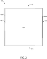
- FIGS. 1-6 depict an exemplary ceiling tile 100 not according to the invention, but this only has two tegular edges and so is not according to the present invention.
- Ceiling tiles 100 are configured for mounting in openings of an overhead support grid 200, as further described herein.
- the ceiling tiles 100 and support grid 200 collectively define a ceiling system 300 having the ability to produce different three-dimensional visual effects by varying the position of the ceiling tiles.
- Ceiling tile 100 includes an upper surface 102, lower surface 104, and four peripheral sides 106, 108, 110, and 112.
- Peripheral sides 106 and 108 are opposing and may each define a tegular edge in profile in one non-limiting embodiment.
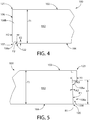
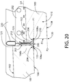
- Peripheral side 106 includes a downward facing offset support surface 106a formed on laterally-extending back flange 106b that is configured to engage a mating upward facing support surface 204 defined on overhead support grid 200 (see, e.g. FIG. 20 ).
- Support surface 106a is defined by recess 107 in side 106 and is offset from the bottom surface 104 of ceiling tile 100 by a vertical distance V2. It will be appreciated that distance V2 also defines the vertical depth of the recess 107.
- Recess 107 defines a laterally outward facing end surface F2 on side 106 of ceiling tile 100 within the recess.
- the end surface F2 (lower portion of surface 106 within recess 107) may be offset horizontally from the upper portion of surface 106 above the recess by a horizontal distance H2.
- the top of end surface F2 may be angled inwards towards the center of the ceiling tile 100.
- Support surface 106a is oriented substantially parallel to bottom surface 104 of ceiling tile 100 in one embodiment.
- Opposing peripheral side 108 includes a downward facing offset support surface 108a formed on laterally-extending back flange 108b that is configured to engage a mating upward facing support surface 204 defined on overhead support grid 200 (see, e.g. FIG. 20 ).
- Support surface 108a is defined by recess 109 in side 108 and is offset from the bottom surface 104 of ceiling tile 100 by a vertical distance V1. It will be appreciated that distance V1 also defines the vertical depth of the recess 109.
- Recess 109 defines a laterally outward facing end surface F1 on side 108 of ceiling tile 100 within the recess.
- the end surface F1 (lower portion of surface 108 within recess 109) may be offset horizontally from the upper portion of surface 108 above the recess by a horizontal distance H1. In one embodiment, the top of end surface F1 may be angled inwards towards the center of the ceiling tile 100. Support surface 108a is oriented substantially parallel to bottom surface 104 of ceiling tile 100 in one embodiment.
- peripheral sides 106 and 108 may be different in configuration to create a three-dimensional visual effect when mounted in the overhead support grid 200 of the ceiling system 300. Accordingly, in one embodiment, recess 109 in peripheral side 108 may be deeper (higher) than recess 107 in peripheral side 106 by making vertical distance V1 larger than vertical distance V2 measured to the offset support surfaces 108a and 106a, respectively. Outward facing end surface F1 within recess 109 will therefore have a greater height and exposed surface area below the overhead support grid 200 than end surface F2 within recess 107. When mounted in overhead support grid 200 (as shown in FIGS.
- the top and bottom surfaces 102, 104 of the ceiling tiles 100 will be angled in orientation (and appearance) with respect to the grid support members 202 due to the difference in recess depths (heights) in peripheral sides 106 and 108.
- the remaining opposing peripheral sides 110 and 112 may have plain or straight edge profiles without any offset support surfaces or recesses.
- the ceiling tiles 100 preferably have a horizontal width measured between sides 110 and 112 that is dimensioned to fit in between opposing grid support members 202 (see, e.g. FIGS. 17-20 ) without engaging upward facing support surface 204 of the grid support members. Sides 110 and 112 therefore do not engage grid support members 202.
- the ceiling tile 100 is supported within the overhead support grid by the tegular edges on opposing peripheral sides 106 and 108. This tile configuration may be used for field tiles (i.e. those not lying along the perimeter of ceiling system 300.
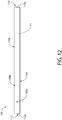
- FIGS. 7-12 show an embodiment of ceiling tile 100 that may be useful for border tiles in which either tegular edge on peripheral sides 106 or 108 may need to be cut or severed by an installer to reduce the width of the tile. This would produce an essentially straight side without a tegular edge that does not engage the overhead support grid 200.
- the remaining opposing peripheral sides 110 and 112 of ceiling tile 100 are also configured with tegular edges.
- Sides 110 and 112 each include an angled downward facing offset support surface 110a and 112a formed on laterally-extending back flanges 110b and 112b, respectively.
- Support surfaces 110a and 112a are defined by recesses 111 and 113 respectively in peripheral sides 110 and 112, and may each be offset from the bottom surface 104 of ceiling tile 100 by a varying vertical distance V3 between sides 106 and 108.
- Support surfaces 110a, 112a are oriented at an angle A1 between 0 and 45 degrees to bottom surface 104 of ceiling tile 100 (thereby producing the varying distance V3).
- angle A1 may be about 3-5 degrees.
- Support surfaces 110a, 112a each intersect downward facing offset support surfaces 106a and 110a such that a continuous rectilinear-shaped peripheral downward facing support surface is formed around all sides of the ceiling tile 100 for engaging the overhead support grid 200, as further described herein.
- This embodiment provides support of the ceiling tile 100 on all sides when hung in full-sized grid openings 208 of support grid 200. Even if either peripheral side 106 or 108 needs to be field trimmed to fit a reduced size grid opening 208, the ceiling tile 100 will still be adequately supported on three remaining peripheral sides by the support surfaces on the back flanges.
- the ceiling tiles 100 have a substantially uniform overall thickness T1 as shown in FIGS. 3-5 between peripheral sides 106 and 108, and further between peripheral sides 110 and 112. Accordingly, top surface 102 is substantially parallel to bottom surface 104 of the ceiling tile 100.
- the angled orientation and appearance of the bottom surfaces 104 of the ceiling tiles 100 (and formation of a reveal on end surface F1 on peripheral side 108 as described further below) is achieved through the different recess depths or heights (i.e. vertical distances V2 and V1) in the tegular edges of peripheral sides 106 and 108 instead of varying the thickness of the ceiling tiles at different spots which would increase the weight of the tiles and be more costly to produce.
- this further minimizes the total installed weight of the ceiling tiles that must be supported by the overhead support grid 200 thereby saving money by allowing structurally lighter grid support members to be provided.
- the reveal When ceiling tile 100 is fully mounted in an angled position to support grid 200, the reveal is created on peripheral side 108 by the projection of end surface F1 below the bottom 206 of the grid support members 202.
- the reveal is visible to room occupants within the space below the ceiling system 300 (see, e.g. FIGS. 13-14 and 18-20 ) and creates a vertical rectangular face projecting below the support grid when viewed head on (i.e. perpendicular to peripheral side 108.
- the end surface F1 preferably is disposed at an angle A2 with respect to the top surface 102 of the ceiling tile 100 as shown in FIG. 5 . Because top and bottom surfaces 102, 104 are parallel to each other, end surface F1 is therefore also disposed at an angle to the bottom surface of the ceiling tile. Angle A2 is measured between a vertical reference line R1 which lies perpendicular to top surface 102 (i.e. 90 degrees thereto) and the plane of the end surface F1. In some exemplary embodiments, angle A2 may be between 0 degrees and 45 degrees depending on the vertical depth of the recess 109 (i.e.
- angle A2 may be about 3-5 degrees.
- angle A3 measured between end surface F1 and downward facing support surface 108a on peripheral side 108 of ceiling tile 100 is preferably at a 90 degree angle A3 (i.e. perpendicular). Downward facing support surface 108a would therefore not be parallel to top and bottom surfaces 102 and 104.
- End surface F2 on opposing peripheral side 106 may be angled similarly to end surface F1 described above, or in other embodiments may be vertically straight (i.e. perpendicular to top and bottom surfaces 102 and 104 of ceiling tile 100 depending on the vertical depth (i.e. vertical distance V2) of recess 107.
- a straight end surface F2 may be used as there may be no reveal or a minimal reveal which would not be noticeable to a room occupant. In one embodiment, a straight end surface F2 is used.
- Ceiling tiles 100 may be made of any suitable material, including for example without limitation fiberglass, a mineral fiber substrate, wood, or other materials and various combinations of materials.
- the ceiling tiles 100 may further be structured to be pliable or non-pliable in various embodiments. Accordingly, the invention is not limited by the selection of ceiling tile material or construction.
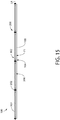
- FIGS. 13-20 depict the overhead support grid 200 for perimeter mounting and hanging the ceiling tiles 100 in ceiling system 300.
- Support grid 200 includes a plurality of intersecting and elongated grid support members 202 forming an array of grid openings 208 configured and dimensioned to receive ceiling tiles 100 therein.
- the grid support members 202 is arranged in an orthogonal pattern forming rectilinear grid openings 208 such as squares or rectangles for ceiling tiles 100 having complementary configured shapes (in top plan view).
- the terminal ends of at least some of the grid support members 202 may be configured to interlock with other transversely oriented grid support members 202 at right angles to form the rectilinear grid pattern in a manner well known to those skilled in the art without further elaboration. Any suitable interlocking mechanism and configuration may be used.
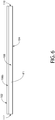
- grid support members 202 may have a generally inverted T-shaped configuration when in the mounted position suspended from a ceiling structure or other overhead support structure.
- grid support members 202 may include a longitudinally-extending horizontal bottom flange 210, a bulbous top stiffening channel 220, and a vertical web 212 extending upwards from the flange to the stiffener.
- the grid support members 202 each define a longitudinal axis LA.
- Web 212 may be centered between opposing side ends of flange 212 in one embodiment.
- Bottom flange 210 further defines a bottom surface 206 facing downwards towards a room or space below the support grid. Bottom surface 206 may be generally disposed opposite support surfaces 204 on the flange. Bottom surface 206 defines a first horizontal reference plane P1 of the overhead support grid 200. In one embodiment, the bottom surfaces 206 of at least four intersecting grid support members 202 defining a grid opening 208 in which a ceiling tile 100 is mounted all lie in the same horizontal reference plane P1. Accordingly, these four intersecting bottom surfaces 206 are positioned at essentially the same elevation.
- grid support member 202 has an inverted T-shaped cross sectional configuration, it will be appreciated that other suitable cross sectional configurations may be used so long as an upward facing support surface 204 is provided on at least some grid support members 202 for holding ceiling tiles 100.
- Grid support members 202 may be supported from and suspended below a ceiling 216 or other overhead support structure (e.g. beam, deck, etc.) by vertical hangers 214 having any suitable configuration including for example without limitation wires, cables, rods, struts, etc.
- Hangers 214 may be attached at one end to the ceiling 216 or other overhead structure by appropriate mounting components (e.g. expansion or anchor lugs, welding, clamps, brackets, etc.) and at an opposite end to the support members 202 by any suitable method (e.g. fasteners, brackets, clamped, threaded rods, etc.).
- Hangers 214 may be spaced along the length of the grid support members 202 at appropriate intervals to properly support the weight of the ceiling tiles 100. Therefore, any suitable number and spacing of hangers 214 may be used.
- Grid support members 202 may be made of metallic or non-metallic material suitable to hold the intended dead or weight load of ceiling tiles 100 without undue deflection.
- support members 110 may be made of metal including aluminum, titanium, steel, or other.
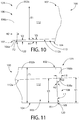
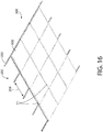
- FIGS. 16 and 17 show a complete ceiling system 300 with ceiling tiles 100 in a fully mounted position supported by the overhead support grid 200.
- FIGS. 13-15 and 18-20 show various side elevation and cross-sectional views of the ceiling system with mounting details of the ceiling tiles 100 in overhead support grid 200.
- the end surface F1 reveals are visible projecting below from the grid support members 202.
- peripheral sides 106 and 108 are shown engaged with grid support members 202 to support the ceiling tiles 100 on at least two opposing sides.
- the downward facing offset support surfaces 106a and 108a formed on laterally-extending back flanges 106b and 108b of ceiling tile 100, respectively, are seated on mating upward facing support surfaces 204 of the grid support members.
- the ceiling tiles 100 which have a substantially uniform thickness T1 are angled in orientation with respect to the support members, and more particularly to horizontal reference plane P1 defined by the bottom surface of the support members.
- the top surface 102 of the ceiling tile 100 slopes downward from peripheral side 106 having a shallow end recess 107 to peripheral side 108 having a deeper end recess 109.
- top surface 102 is disposed at an angle A4 (indicated in FIG. 14 ) formed between horizontal reference plane P1 and the top surface.
- the bottom surface 104 slopes downward from peripheral side 106 to peripheral side 108.
- Bottom surface 104 is disposed at an angle A5 (indicated in FIG. 14 ) formed between horizontal reference plane P1 and the bottom surface.
- the bottom corner 120 on peripheral side 108 projects below the bottom surface 206 of grid support member 202 and horizontal reference plane P1 by vertical distance D1 which corresponds to the height of the end surface F1 reveal that is visible to a room occupant.
- Ceiling tile bottom corner 120 defines a second horizontal reference plane P2 which lies parallel to horizontal reference plane P1.
- the bottom corner 122 on the opposing peripheral side 106 of ceiling tile 100 lies substantially on the horizontal reference plane P1 as shown in FIGS. 14 and 20 . Accordingly, the bottom corner 122 and bottom surface 104 of the ceiling tile adjacent peripheral side 106 is substantially flush with the bottom surface 206 of the grid support members 202 so that the grid support members essentially visually disappears at this side of the ceiling tile. It bears noting that top corner 121 on peripheral side 106 of ceiling tile 100 is located higher than opposing top corner 123 on side 108 when the ceiling tile is in the fully mounted position (with respect to horizontal reference plane P1) because of the angled or slanted mounting position of the tile.
- FIGS. 7-11 If the embodiment of ceiling tile 100 shown in FIGS. 7-11 is used with sloping or angled back flanges 110b and 112b formed on tegular-edged peripheral sides 110 and 112, the angled downward facing offset support surfaces 110a and 112a would engage and rest on upward facing support surfaces 204 of the grid support members 202 (shown extending horizontally side-to-side in FIGS. 14 and 20 ).
- FIG. 14 identifies support surface 110a in dashed lines to represent this engagement
- the engagement on opposite peripheral side 110 not visible in FIG. 14 would be identical.
- ceiling tile 100 shown in FIGS. 1-6 having straight peripheral sides 110 and 112 without angled or sloping tegular edges is used instead, the straight sides would not engage grid support members 202. Rather, the straight peripheral sides 110, 112 would simply pass alongside the horizontal bottom flange 210 of and through the grid support member 202.
- a method of mounting the ceiling tiles 100 in overhead support grid 200 may include holding a ceiling tile in a tilted or angled position (to horizontal) and then inserting one of peripheral sides 106 or 108 upwards into a grid support member 202 through a grid opening 208 from below the support grid 200.
- peripheral side 106 is higher than peripheral side 108 which would be positioned below the support grid 200 and opening 208.
- Back flange 106b on peripheral side 106 of ceiling tile 100 may then be positioned and located above horizontal bottom flange 210 and over an upward facing support surface 204 on the bottom flange.
- peripheral side 106 may then be lowered to engage downward facing support surface 106a of the ceiling tile with support surface 204 on the bottom flange 2 10 of grid support member 202.
- the ceiling tile 100 may still be in a generally tilted or angled position with peripheral side 106 being higher than peripheral side 108 which may still be positioned below the support grid 200 and opening 208.
- the remaining peripheral side 108 is then rotated upwards (clockwise for example in FIGS. 19 and 20 ) so that back flange 108b moves upwards through grid opening 208 to a position just slightly higher than bottom flange 210 of grid support member 202.
- the offset horizontal distances H2 and H12 on peripheral sides 106, 108 respectively are large enough to provide adequate lateral play for inserting one side 106 and then the remaining side 108 through the grid opening 208 between two grid support members 202.
- Back flange 108b on peripheral side 108 of ceiling tile 100 may then be positioned and located above horizontal bottom flange 210 and over an upward facing support surface 204 on the bottom flange of grid support member 202.
- the peripheral side 108 may then be lowered to engage downward facing support surface 108a of the ceiling tile with support surface 204 on the bottom flange 210 of the grid support member 202.
- the ceiling tile 100 is now fully mounted at the perimeter to the overhead support grid 200.
- peripheral side 108 was inserted first into the support grid 200 in lieu of peripheral side 106 during the ceiling tile mounting procedure, the foregoing installation sequence would simply be reversed.
- ceiling tile 100 By varying the horizontal orientation of ceiling tile 100 in grid openings 208, numerous customizable ornamental ceiling configurations may be created by selecting various combinations of positions for the end surface F1 reveal on peripheral side 108.
- FIGS. 21A-B show one exemplary pattern producing a shingled visual effect.
- the end surface F1 reveals on peripheral sides 108 are positioned parallel to each other and at opposing ends of adjacent grid openings 208 (the arrows pointing to the location of end surface F1 reveals on each ceiling tile 100).
- the ceiling tiles 100 have a square shape in top plan view in this embodiment.
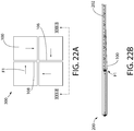
- FIGS. 22A-B show another exemplary pattern producing a pinwheel visual effect.
- the end surface F1 reveals on peripheral sides 108 are positioned at right angles to each other in adjacent grid openings 208 (the arrows pointing to the location of end surface F1 reveals on each ceiling tile 100).
- the ceiling tiles 100 have a square shape in top plan view in this embodiment.
- FIGS. 23A-B show another exemplary pattern producing a faceted hill and valley visual effect.
- the end surface F1 reveals on peripheral sides 108 are positioned parallel to each other and at adjoining ends of adjacent grid openings 208 (the arrows pointing to the location of end surface F1 reveals on each ceiling tile 100).
- the ceiling tiles 100 have a square shape in top plan view in this embodiment.
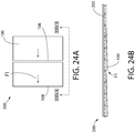
- FIGS. 24A-B show one exemplary pattern producing a shingled visual effect using ceiling tiles 100 having a rectangular or plank shape in top plan view in this embodiment. It will be appreciated that the rectangular ceiling tiles 100 may also be arranged in the foregoing pinwheel or hill and valley patterns.
- the end surface F1 reveals on peripheral sides 108 are positioned at opposing ends of adjacent grid openings 208 (the arrows pointing to the location of end surface F1 reveals on each ceiling tile 100).
Landscapes
- Engineering & Computer Science (AREA)
- Architecture (AREA)
- Physics & Mathematics (AREA)
- Electromagnetism (AREA)
- Civil Engineering (AREA)
- Structural Engineering (AREA)
- General Engineering & Computer Science (AREA)
- Mechanical Engineering (AREA)
- Finishing Walls (AREA)
- Residential Or Office Buildings (AREA)
- Connection Of Plates (AREA)
- Clamps And Clips (AREA)
- Roof Covering Using Slabs Or Stiff Sheets (AREA)
- Building Environments (AREA)
Claims (9)
- Deckensystem (300), umfassend:ein Überkopftragegitter (200), das eine untere Fläche (206) umfasst, wobei das Überkopftragegitter eine Gitteröffnung definiert, die zum Anordnen einer Deckenplatte (100) darin konfiguriert ist; undeine Deckenplatte (100), die in der Gitteröffnung positioniert ist und eine obere Fläche (102) und eine untere Fläche (104) aufweist, wobei die Deckenplatte (100) eine erste Tegularkante (108), die das Tragegitter (200) in Eingriff nimmt, und eine entgegengesetzte zweite Tegularkante (106), die das Tragegitter (200) in Eingriff nimmt, aufweist, wobei die erste Tegularkante (108) eine Konfiguration aufweist, die sich von der der zweiten Tegularkante (106) unterscheidet;eine dritte abgewinkelte Tegularkante (110) und eine entgegengesetzte vierte abgewinkelte Tegularkante (112), die beide in einem 90-Grad-Winkel zu der ersten und der zweiten Tegularkante (108, 106) an der Deckenplatte angeordnet sind, wobei die dritte abgewinkelte Tegularkante (110) eine nach unten weisende dritte Tragefläche (110a) definiert, die eine nach oben weisende Tragefläche (204) in Eingriff nimmt, die auf dem Tragegitter (200) ausgebildet ist, und die entgegengesetzte vierte Tegularkante (112) eine nach unten weisende vierte Tragefläche (112a) definiert, die eine nach oben weisende Tragefläche (204) in Eingriff nimmt, die auf dem Tragegitter (200) ausgebildet ist, dadurch gekennzeichnet, dass die dritte und die vierte Tragefläche (110a, 112a) in einem Winkel zwischen 0 und 45 Grad zu der oberen und der unteren Fläche (104) der Deckenplatte (100) angeordnet sind;wobei die Deckenplatte (100) eine im Wesentlichen einheitliche Dicke zwischen der ersten und der zweiten Tegularkante (108, 106) aufweist und die obere Fläche (102) und die untere Fläche (104) der Deckenplatte (100) in Bezug auf das Tragegitter (200) abgewinkelt sind, wenn sie darin montiert ist, und die untere Fläche (104) im Wesentlichen parallel zu der oberen Fläche (102) der Deckenplatte (100) ist; undwobei die untere Fläche (104) der Deckenplatte (100) im Wesentlichen bündig mit der unteren Fläche des Tragegitters (200) an der zweiten Tegularkante ist.
- Deckensystem (300) nach Anspruch 1, wobei die erste Tegularkante (108) eine tiefe Aussparung (109) aufweist und die zweite Tegularkante (106) eine seichte Aussparung (107) aufweist, wobei die erste Tegularkante (108) in dem Tragegitter (200) niedriger als die zweite Tegularkante (106) sitzt.
- Deckensystem (300) nach Anspruch 2, wobei die Deckenplatte (100) in einer abgewinkelten Position aufliegt, wenn sie in dem Tragegitter (200) montiert ist.
- Deckensystem (300) nach Anspruch 1, wobei die erste Tegularkante (108) eine Endfläche beinhaltet, die eine freigelegte Leibung definiert, die unter dem Tragegitter (200) sichtbar ist.
- Deckensystem (300) nach Anspruch 4, wobei eine Oberseite der Endfläche der ersten Tegularkante (108) nach innen zu einer Mitte der Platte (100) hin abgewinkelt ist.
- Deckensystem (300) nach Anspruch 4, wobei die Endfläche der ersten Tegularkante (108) nicht senkrecht zu der oberen Fläche (102) der Deckenplatte (100) ist.
- Deckensystem (300) nach Anspruch 6, wobei die Endfläche der ersten Tegularkante (108) zwischen 0 und 45 Grad zu einer vertikalen Bezugslinie ist, die senkrecht zu der oberen Fläche (102) der Deckenplatte ist.
- Deckensystem (300) nach Anspruch 1, wobei:die erste Tegularkante (108) eine nach unten weisende erste Tragefläche (108a) definiert, die eine nach oben weisende Tragefläche (204) in Eingriff nimmt, die auf dem Tragegitter (200) ausgebildet ist, unddie entgegengesetzte zweite Tegularkante (106) eine nach unten weisende zweite Tragefläche (106a) definiert, die eine nach oben weisende Tragefläche (204) in Eingriff nimmt, die auf dem Tragegitter (200) ausgebildet ist, wobei die erste Tragefläche (108a) in einem größeren vertikalen Abstand von der unteren Fläche (104) der Deckenplatte als die zweite Tragefläche (106a) angeordnet ist, so dass die Deckenplatte (100) in Bezug auf das Tragegitter (200) abgewinkelt ist, wenn sie darin montiert ist.
- Deckensystem (300) nach Anspruch 1, wobei die dritte und die vierte Tragefläche (110a, 112a) nicht parallel zu der unteren Fläche (104) der Deckenplatte (100) sind.
Applications Claiming Priority (2)
| Application Number | Priority Date | Filing Date | Title |
|---|---|---|---|
| US201261696424P | 2012-09-04 | 2012-09-04 | |
| PCT/US2013/058010 WO2014039528A1 (en) | 2012-09-04 | 2013-09-04 | Ceiling system |
Publications (2)
| Publication Number | Publication Date |
|---|---|
| EP2893099A1 EP2893099A1 (de) | 2015-07-15 |
| EP2893099B1 true EP2893099B1 (de) | 2018-08-15 |
Family
ID=49170914
Family Applications (2)
| Application Number | Title | Priority Date | Filing Date |
|---|---|---|---|
| EP13765558.5A Active EP2893100B1 (de) | 2012-09-04 | 2013-09-04 | Deckensystem mit einem verborgenen gitter |
| EP13762676.8A Active EP2893099B1 (de) | 2012-09-04 | 2013-09-04 | Deckensystem |
Family Applications Before (1)
| Application Number | Title | Priority Date | Filing Date |
|---|---|---|---|
| EP13765558.5A Active EP2893100B1 (de) | 2012-09-04 | 2013-09-04 | Deckensystem mit einem verborgenen gitter |
Country Status (12)
| Country | Link |
|---|---|
| US (4) | US9376813B2 (de) |
| EP (2) | EP2893100B1 (de) |
| CN (2) | CN104641053B (de) |
| AU (2) | AU2013312843B2 (de) |
| CA (2) | CA2883917C (de) |
| DK (1) | DK2893100T3 (de) |
| IN (2) | IN2015DN02448A (de) |
| MX (1) | MX365613B (de) |
| PL (1) | PL2893100T3 (de) |
| RU (2) | RU2608371C2 (de) |
| SG (2) | SG11201501652YA (de) |
| WO (2) | WO2014039528A1 (de) |
Families Citing this family (39)
| Publication number | Priority date | Publication date | Assignee | Title |
|---|---|---|---|---|
| US8596009B2 (en) | 2010-11-01 | 2013-12-03 | Awi Licensing Company | Suspended ceiling system, securing members, and process of installing a suspended ceiling system |
| IN2015DN02448A (de) | 2012-09-04 | 2015-09-04 | Armstrong World Ind Inc | |
| US10267039B2 (en) * | 2012-09-04 | 2019-04-23 | Awi Licensing Llc | Ceiling systems |
| AU2015251495B2 (en) * | 2014-04-23 | 2019-08-29 | Locking Key Pty Ltd As Trustee For Locking Key Unit Trust | A suspended ceiling clip |
| US9194123B2 (en) * | 2014-04-29 | 2015-11-24 | Awi Licensing Company | Ceiling system |
| US9845598B1 (en) * | 2014-06-23 | 2017-12-19 | Hanson Hsu | Apparatus for improving the acoustics of an interior space, a system incorporating said apparatus and method of using said apparatus |
| EP2998457B1 (de) * | 2014-09-19 | 2017-10-25 | Saint-Gobain Ecophon AB | Verfahren und -Platte zur Verwendung in einer abgehängten Decke oder Wand und eine abgehängte Decke oder Wand |
| US10113317B1 (en) | 2015-04-16 | 2018-10-30 | Gordon Sales, Inc. | Apparatus and method for hanging architectural panels with concealed attachment points |
| US9328510B1 (en) * | 2015-07-07 | 2016-05-03 | Awi Licensing Company | Ceiling system |
| USD782075S1 (en) * | 2015-08-31 | 2017-03-21 | United Construction Products, Inc. | Flooring tile |
| US10465385B2 (en) * | 2016-06-17 | 2019-11-05 | AES Clean Technology, Inc. | Clean room ceiling, system and installation method |
| GB2558759B (en) * | 2016-12-02 | 2020-02-19 | Gripple Ltd | Suspension assembly |
| GB201621218D0 (en) * | 2016-12-14 | 2017-01-25 | Ge Oil & Gas Uk Ltd | Wire securement |
| USD788948S1 (en) * | 2017-01-04 | 2017-06-06 | United Construction Products, Inc. | Flooring tile |
| PL3684984T3 (pl) | 2017-09-21 | 2023-03-06 | Hilti Aktiengesellschaft | Łącznik |
| CN109538618B (zh) * | 2017-09-21 | 2021-04-27 | 喜利得股份公司 | 一种紧固件 |
| USD840718S1 (en) * | 2017-11-13 | 2019-02-19 | Zeager Brothers, Inc. | Playground mat |
| RU2663519C1 (ru) * | 2017-12-04 | 2018-08-07 | Александр Васильевич Гущин | Универсальная декоративная подвесная рамочная потолочная система на гибких подвесах |
| US11486423B2 (en) * | 2017-12-21 | 2022-11-01 | Illinois Tool Works Inc. | Linear latching systems and methods |
| CA3028284A1 (en) * | 2017-12-29 | 2019-06-29 | Certainteed Ceilings Corporation | Suspension ceiling support clip |
| WO2019238717A1 (en) * | 2018-06-13 | 2019-12-19 | Assa Abloy Entrance Systems Ab | Space saving mechanism for installation of swing door operator |
| EP3587693B1 (de) * | 2018-06-29 | 2023-01-04 | Certainteed Canada, Inc. | Verbindungsclip zur befestigung ein stützgitter |
| USD890366S1 (en) * | 2018-11-13 | 2020-07-14 | Arktura Llc | Architectural fixture |
| USD890959S1 (en) * | 2018-11-13 | 2020-07-21 | Arktura Llc | Architectural fixture |
| USD890368S1 (en) * | 2018-12-19 | 2020-07-14 | Arktura Llc | Architectural fixture |
| USD890367S1 (en) * | 2018-12-19 | 2020-07-14 | Arktura Llc | Architectural fixture |
| CN109487932B (zh) * | 2018-12-25 | 2023-09-26 | 中国建筑西南设计研究院有限公司 | 一种角度可调的插芯式遮阳格栅系统 |
| US10975569B1 (en) | 2019-11-22 | 2021-04-13 | Gaylen A. Haas | Continuous rail, drop ceiling system and components |
| KR102365717B1 (ko) * | 2020-01-03 | 2022-02-22 | 주식회사 젠픽스 | 천장 어셈블리 |
| BR112022015438A2 (pt) * | 2020-02-07 | 2022-09-27 | Armstrong World Ind Inc | Painéis de construção de atenuação de som |
| EP4001539A1 (de) * | 2020-11-18 | 2022-05-25 | Saint-Gobain Ecophon AB | Akustikplatte, aufgehängtes akustisches system mit einer solchen akustikplatte und sockelleiste |
| CN112663852A (zh) * | 2020-12-08 | 2021-04-16 | 中国建筑第八工程局有限公司 | 格栅吊顶和灯具用的安装结构及其安装方法 |
| US11879250B2 (en) | 2020-12-11 | 2024-01-23 | Awi Licensing Llc | Panel assembly for a suspended ceiling system, corner bracket thereof, and related methods |
| US11873643B2 (en) | 2020-12-11 | 2024-01-16 | Awi Licensing Llc | Overhead grid assembly, bracket member thereof, and ceiling system including the same |
| US11920355B2 (en) * | 2021-12-23 | 2024-03-05 | 0776425 B.C. Ltd. | Building material attachment devices, systems, and associated methods of manufacture and use |
| US12031327B1 (en) | 2022-08-29 | 2024-07-09 | Gordon Sales, Inc. | Suspended ceiling grid hanging system |
| US20250297476A1 (en) * | 2024-03-20 | 2025-09-25 | Saudi Arabian Oil Company | Suspended ceiling system and method |
| GB2641239A (en) * | 2024-05-20 | 2025-11-26 | Sterling Gp Holdings Ltd | Mesh Deck Appliance Bracket |
| CA239739S (en) * | 2024-06-12 | 2026-01-15 | Acoufelt Llc | T-grid clip |
Family Cites Families (138)
| Publication number | Priority date | Publication date | Assignee | Title |
|---|---|---|---|---|
| US419388A (en) * | 1890-01-14 | Ceiling-block | ||
| US2045311A (en) | 1933-07-20 | 1936-06-23 | United States Gypsum Co | Acoustical wall covering |
| US2126956A (en) | 1936-04-07 | 1938-08-16 | Royce W Gilbert | Wall construction |
| US2066255A (en) | 1936-04-22 | 1936-12-29 | Copper Houses Inc | Building construction |
| US2335303A (en) | 1941-10-13 | 1943-11-30 | Anders C Olsen | Building structure |
| GB703753A (en) | 1950-07-04 | 1954-02-10 | James Gwyn Davies | Ceilings of buildings |
| US2859469A (en) * | 1956-01-27 | 1958-11-11 | Illinois Tool Works | Assembly and fastener therefor |
| US2935152A (en) * | 1956-05-15 | 1960-05-03 | Maccaferri Mario | Acoustical units and installed assemblies thereof |
| US3032833A (en) | 1957-04-22 | 1962-05-08 | Duo Flex Corp | Demountable acoustical ceiling |
| US2898640A (en) | 1957-11-29 | 1959-08-11 | Paul D Dail | Ceiling construction |
| US3149693A (en) | 1960-08-01 | 1964-09-22 | Owens Corning Fiberglass Corp | Acoustical surfaces |
| BE676985A (de) | 1965-02-26 | 1966-08-24 | ||
| US3380206A (en) | 1965-09-29 | 1968-04-30 | Soundlock Corp | Lay-in acoustical ceiling panel with flexible diaphragms |
| US3456411A (en) | 1966-11-03 | 1969-07-22 | Flintkote Co | Ceiling tile system |
| US3708935A (en) | 1966-11-07 | 1973-01-09 | Nat Gypsum Co | Simulated monolithic predecorated wall construction |
| US3710520A (en) * | 1971-02-17 | 1973-01-16 | S Federowicz | Utility frame for suspended ceiling construction |
| US3748804A (en) | 1971-07-16 | 1973-07-31 | George P De | Suspended ceiling system |
| FR2214800B3 (de) | 1973-01-24 | 1976-01-30 | Picard Michel Fr | |
| US3919443A (en) | 1973-06-05 | 1975-11-11 | W H Porter Inc | Construction panel having overlapping edges and foam backing |
| DK133480B (da) | 1973-08-29 | 1976-05-24 | Finn Andersen | Underloft. |
| US3869760A (en) * | 1973-09-20 | 1975-03-11 | Usm Corp Of Flemington New Jer | Retaining clip formed from sheet material |
| US4040213A (en) | 1975-08-22 | 1977-08-09 | Capaul Raymond W | Unitary structural panel for ceiling and wall installations |
| US4284447A (en) | 1976-02-20 | 1981-08-18 | Dickens Luther I | Method of manufacturing a composite panel |
| US4026081A (en) | 1976-05-26 | 1977-05-31 | Aluflex Partitions (Eastern 1970) Ltd. | Suspended ceiling panel |
| US4117642A (en) | 1977-07-29 | 1978-10-03 | Armstrong Cork Company | Ceiling panel attachment clip |
| US4155206A (en) | 1978-04-19 | 1979-05-22 | Howmet Corporation | Insulated metal roofing system |
| US4241555A (en) | 1978-05-30 | 1980-12-30 | Radva Plastics Corporation | Composite panel structure and method of manufacture |
| NL7909311A (nl) * | 1979-12-27 | 1980-03-31 | Joannes Willibrordus Mosch | Systeemwand of -plafond. |
| FR2516129A1 (fr) | 1981-11-12 | 1983-05-13 | Bacci Robert | Plafonds chauffants par panneaux composites industrialises a modules variables et son procede de mise en oeuvre |
| GB2152091B (en) | 1983-12-22 | 1987-05-20 | Special Acoustic Services Limi | Suspended ceiling |
| CA1229462A (en) | 1984-06-04 | 1987-11-24 | Sigismund W. Srocki | Monolithic ceiling for manufactured housing |
| DE3502635A1 (de) | 1985-01-26 | 1986-07-31 | Konrad 8261 Winhöring Voringer | Abhaengevorrichtung |
| US4640064A (en) | 1985-03-18 | 1987-02-03 | Donn Incorporated | Suspension ceiling system combining snap-up pans and lay-in panels |
| US4586308A (en) | 1985-06-03 | 1986-05-06 | U.S. Plywood Corporation | Wall panel |
| US4742662A (en) * | 1986-05-05 | 1988-05-10 | Smith Owen J | Ceiling trim support clips |
| US4696141A (en) * | 1986-06-19 | 1987-09-29 | Simplex Ceiling Corp. | Suspended ceiling having a concealed suspension grid and lay-in metal panels supported thereon |
| SE461048B (sv) | 1987-03-02 | 1989-12-18 | Gyproc Ab | Perforerad, ljudabsorberande skiva |
| US4926606A (en) * | 1988-11-14 | 1990-05-22 | Hanson Carl E | Ornamental ceiling system |
| US4991370A (en) | 1989-01-11 | 1991-02-12 | Alcan Aluminum Corporation | Security panel system |
| US5628159A (en) | 1989-12-14 | 1997-05-13 | Younts; Patty L. | Joint strip, method of forming a wall using the joint strip and wall made therefrom |
| US5001879A (en) | 1990-01-30 | 1991-03-26 | Therm-All, Inc. | Building insulation |
| US5085022A (en) | 1990-01-30 | 1992-02-04 | Therm-All, Inc. | Building insulation |
| US5050360A (en) * | 1990-04-18 | 1991-09-24 | Alcan Aluminum Corporation | Suspended ceiling panel |
| US5182893A (en) | 1990-08-08 | 1993-02-02 | Goodworth John P | Panel, clip and method of mounting panel |
| US5174849A (en) | 1991-01-11 | 1992-12-29 | Capaul Raymond W | Method for manufacturing a lay-in ceiling panel |
| US5202174A (en) | 1991-01-11 | 1993-04-13 | Capaul Corporation | Lay-in ceiling panel |
| US5079042A (en) | 1991-02-21 | 1992-01-07 | Solid Products, Inc. | Drywall joint finishing system |
| US5236757A (en) | 1991-05-20 | 1993-08-17 | E. I. Du Pont De Nemours And Company | Glass composite sheathing board having an air retarder and water barrier sheet laminated thereto |
| US5313759A (en) | 1991-12-18 | 1994-05-24 | Chase Iii Francis H | Cleanroom ceiling system |
| US5349796A (en) | 1991-12-20 | 1994-09-27 | Structural Panels, Inc. | Building panel and method |
| WO1993017197A1 (en) * | 1992-02-28 | 1993-09-02 | Armstrong World Industries, Inc. | Decorative elements for subceilings |
| US5401133A (en) | 1993-09-16 | 1995-03-28 | Wildeck, Inc. | Security washer for security paneling system |
| US5507125A (en) | 1994-06-13 | 1996-04-16 | Mcclure; Roberta | Ceiling panel with stiffly flexible edges, and ceiling |
| US5486394A (en) | 1994-08-26 | 1996-01-23 | E-Z Taping System, Inc. | Self-release self-adhesive drywall tape |
| US5609007A (en) * | 1995-02-06 | 1997-03-11 | Eichner; Vincent T. | Integrated refacing system for suspended ceilings |
| CN2256443Y (zh) | 1996-06-07 | 1997-06-18 | 刘仁演 | 轻钢架的立体型天花板 |
| US5839246A (en) * | 1996-09-12 | 1998-11-24 | Worthington Armstrong Venture | Grid framework for suspended ceiling |
| US6079177A (en) | 1998-07-28 | 2000-06-27 | Halchuck; Michael A. | Removable ceiling panel assembly |
| US6108994A (en) | 1998-08-12 | 2000-08-29 | Armstrong World Industries, Inc. | Ceiling panel |
| US6029413A (en) * | 1998-10-14 | 2000-02-29 | Compas, Jr.; Albert W. | Dropped ceiling support frame |
| DE29901043U1 (de) * | 1999-01-22 | 1999-05-06 | AMF-Mineralplatten GmbH Betriebs KG, 94481 Grafenau | Deckenplatte einer Unterdecke |
| US6145264A (en) | 1999-02-01 | 2000-11-14 | Dallaire; Michel | Bracket for suspended ceiling tiles |
| US6305137B1 (en) | 1999-08-30 | 2001-10-23 | Acoustic Ceiling Products, L.L.C. | Covering for suspended ceiling grid system |
| BE1013148A3 (nl) * | 1999-11-23 | 2001-10-02 | Unilin Beheer Bv | Bekleding alsmede elementen voor het vormen van dergelijke bekleding. |
| US20020014051A1 (en) | 2000-04-20 | 2002-02-07 | Fraval Hanafi R. | High strength light-weight fiber ash composite material, method of manufacture thereof, and prefabricated structural building members using the same |
| JP4790961B2 (ja) * | 2000-05-25 | 2011-10-12 | リパスキ,ジヨン | バラストブロックデッキシステムス及びその台座組立体 |
| US6467228B1 (en) | 2000-11-22 | 2002-10-22 | Usg Interiors, Inc. | Hinged ceiling panel |
| US6610160B2 (en) | 2000-11-29 | 2003-08-26 | Donald W. Harrison | Method for resurfacing a ceiling tile |
| IT251807Y1 (it) * | 2000-12-28 | 2004-01-20 | Networking Business Company Di | Elemento di ancoraggio di sottosquadro per il fissaggio di lastre e/opiastrelle. |
| US20020112424A1 (en) * | 2001-02-22 | 2002-08-22 | Vib Inc. | Suspended ceiling support structure |
| US6807785B2 (en) * | 2001-09-11 | 2004-10-26 | Usg Interiors, Inc. | Moiré ceiling panels |
| US7658046B2 (en) * | 2001-09-11 | 2010-02-09 | Usg Interiors, Inc. | Moiré ceiling panels |
| CA2468523A1 (en) | 2001-11-28 | 2003-06-05 | Weiling Peng | Adhesive-edge building panel and method of manufacture |
| US6782670B2 (en) * | 2001-12-28 | 2004-08-31 | Usg Interiors, Inc. | Multi-planar ceiling system |
| US7076928B2 (en) | 2002-02-04 | 2006-07-18 | Owens Corning Fiberglas Technology, Inc. | Suspended ceiling panel edge and rib technology |
| US6722098B2 (en) | 2002-02-21 | 2004-04-20 | Worthington Armstrong Venture | Beam for drywall ceiling |
| EP1387016B1 (de) | 2002-07-30 | 2006-12-27 | Hunter Douglas Industries B.V. | Paneelaufbau für abgehängte Decken |
| US7017317B2 (en) * | 2002-10-04 | 2006-03-28 | Leonard Thomas Capozzo | Decorative ceiling panel and fastening system |
| EP1489241A1 (de) | 2003-06-20 | 2004-12-22 | Schneider Dämmtechnik AG | Anordnung zum Befestigen von Deckenelementen |
| EP1689954B1 (de) | 2003-12-01 | 2017-01-04 | Erich R. Vogl | Verfahren zur herstellung von abgehängten decken aus gipskar ton-platten |
| US20050193668A1 (en) | 2004-02-23 | 2005-09-08 | Hamilton Coatings, Llc | Drywall joint construction and method |
| US20050217194A1 (en) | 2004-03-30 | 2005-10-06 | Eric Krantz-Lilienthal | Trim system for a suspended ceiling |
| WO2005095727A1 (en) | 2004-04-02 | 2005-10-13 | Rockwool International A/S | Acoustic elements and their production |
| CN2727297Y (zh) | 2004-09-03 | 2005-09-21 | 毛卫平 | 梯级宽斜边复合天花板 |
| US7607271B2 (en) | 2004-11-09 | 2009-10-27 | Johns Manville | Prefabricated multi-layer roofing panel and system |
| US7536836B2 (en) | 2005-01-13 | 2009-05-26 | Roberto Felipe Moser Rossel | Removable ceiling panel |
| US7681370B2 (en) * | 2005-07-20 | 2010-03-23 | Awi Licensing Company | Suspension systems |
| CN101283150A (zh) * | 2005-08-02 | 2008-10-08 | 欧文斯科宁知识产权资产有限公司 | 更新吊顶板的方法 |
| US7770346B2 (en) | 2005-08-30 | 2010-08-10 | Specialty Hardware L.P. | Fire-retardant cementitious shear board having metal backing with tab for use as underlayment panel for floor or roof |
| US20070125042A1 (en) | 2005-11-22 | 2007-06-07 | John Hughes | Structural insulated panel construction for building structures |
| AT503229B1 (de) * | 2005-12-01 | 2009-07-15 | Neuhofer Franz Jun | Vorrichtung zum befestigen eines abdeckprofils für den übergang zwischen zwei zueinander senkrechten flächen |
| US20070193131A1 (en) | 2006-02-21 | 2007-08-23 | Francisco Ortiz | Acoustical panel ceiling system |
| US8176701B2 (en) | 2006-05-10 | 2012-05-15 | Cullen Leslie D | Insulative siding apparatus and method of making the same |
| US7841149B2 (en) * | 2006-10-16 | 2010-11-30 | Chicago Metallic Corporation | Concealed ceiling panel system |
| US20080148665A1 (en) * | 2006-12-21 | 2008-06-26 | Yonash Richard F | Ceiling tiles made of rigid pvc |
| US7712274B2 (en) | 2006-12-29 | 2010-05-11 | Usg Interiors, Inc. | Downwardly accessible lift-and-shift ceiling system |
| US7937903B2 (en) | 2007-03-07 | 2011-05-10 | Portafab | Panelized ceiling system |
| MX367591B (es) | 2007-03-21 | 2019-08-27 | Ash Tech Ind L L C | Materiales utilitarios que incorporan una matriz de micropartículas. |
| US20090239429A1 (en) | 2007-03-21 | 2009-09-24 | Kipp Michael D | Sound Attenuation Building Material And System |
| US20090239059A1 (en) | 2007-03-21 | 2009-09-24 | Kipp Michael D | Wallboard Materials Incorporating a Microparticle Matrix |
| RU2496953C2 (ru) * | 2007-06-08 | 2013-10-27 | Армстронг Уорлд Индастриз, Инк. | Подвесная система |
| NL1034759C2 (nl) | 2007-11-26 | 2009-05-27 | Benjamin Martinus Schoonewagen | Systeemplafond. |
| US7765762B2 (en) | 2008-01-08 | 2010-08-03 | Usg Interiors, Inc. | Ceiling panel |
| GB2456328A (en) | 2008-01-11 | 2009-07-15 | Usg Interiors Inc | Grid members for a suspended ceiling and methods of making same |
| US8672600B2 (en) * | 2008-02-07 | 2014-03-18 | Tinnerman Palnut Engineered Products, Inc. | Deck clip |
| CA2736090A1 (en) | 2008-09-03 | 2010-03-11 | Usg Interiors, Inc. | Electrically conductive tape for walls and ceilings |
| US7836652B2 (en) | 2008-09-22 | 2010-11-23 | Sanford Lloyd Futterman | System and method for sealing joints between exterior wall panels |
| US8056294B2 (en) | 2008-12-09 | 2011-11-15 | Usg Interiors, Inc. | Concealed suspension ceiling with downward removable panels |
| CN201351320Y (zh) | 2009-01-15 | 2009-11-25 | 阿姆斯壮世界工业(中国)有限公司 | 天花板的镶板 |
| EP2401444B1 (de) | 2009-02-27 | 2015-11-25 | AWI Licensing Company | Lineares oberflächenabdeckungssystem |
| US8359802B1 (en) * | 2009-07-29 | 2013-01-29 | Sauder Woodworking Co. | Ceiling system |
| ES1071088Y (es) * | 2009-09-18 | 2010-04-07 | Ebanisteria Aguera S A | Dispositivo para la fijacion de paneles |
| US20110076470A1 (en) | 2009-09-29 | 2011-03-31 | Certainteed Corporation | Method of making aesthetic panels with enhanced acoustic performance |
| US20110078970A1 (en) * | 2009-10-01 | 2011-04-07 | Certainteed Corporation | Ceiling tile and edge suspension system |
| WO2011088184A2 (en) | 2010-01-13 | 2011-07-21 | Pacific Insulated Panel, Llc | Composite insulating building panel and system and method for attaching building panels |
| EP2528736B1 (de) | 2010-01-28 | 2014-09-17 | Havco Wood Products LLC | Flexible, überlappende verbundstoffverbindung für anhängerböden |
| US8176700B2 (en) * | 2010-04-07 | 2012-05-15 | Eaton Corporation | Clip-on extruded moldings for ceiling grid |
| US8632040B2 (en) * | 2010-04-29 | 2014-01-21 | Cisco Technology, Inc. | Low profile mounting of electronic devices |
| US8745947B2 (en) * | 2010-06-24 | 2014-06-10 | Chicago Metallic Company Llc | Accessible concealed suspended ceiling system |
| US8484923B2 (en) | 2010-12-06 | 2013-07-16 | Usg Interiors, Llc | Bi-parting accessible ceiling system |
| US8544229B2 (en) * | 2011-07-13 | 2013-10-01 | A. Raymond Et Cie | Decking system with hidden dovetail fastener |
| US8646238B2 (en) * | 2011-12-22 | 2014-02-11 | Usg Interiors, Llc | Apparatus, system, and method for facilitating use of thin flexible scrims in a grid-type suspended ceiling |
| EP2662504B1 (de) * | 2012-05-09 | 2014-11-19 | Saint-Gobain Ecophon AB | Nicht planare Hängedecke |
| US8925677B2 (en) | 2012-06-27 | 2015-01-06 | Usg Interiors, Llc | Gypsum-panel acoustical monolithic ceiling |
| US8684134B2 (en) | 2012-06-27 | 2014-04-01 | Usg Interiors, Llc | Gypsum-panel acoustical monolithic ceiling |
| US8770345B2 (en) | 2012-06-27 | 2014-07-08 | Usg Interiors, Llc | Gypsum-panel acoustical monolithic ceiling |
| US9938717B2 (en) | 2015-03-18 | 2018-04-10 | Awi Licensing Llc | Faced ceiling system |
| IN2015DN02448A (de) | 2012-09-04 | 2015-09-04 | Armstrong World Ind Inc | |
| US9556613B1 (en) | 2016-05-24 | 2017-01-31 | Awi Licensing Llc | Ceiling system |
| US10267039B2 (en) * | 2012-09-04 | 2019-04-23 | Awi Licensing Llc | Ceiling systems |
| EP2929103B1 (de) | 2012-12-06 | 2017-08-02 | Armstrong World Industries, Inc. | Deckensystem |
| US9140004B2 (en) | 2013-01-23 | 2015-09-22 | Paul Hansen | Sound control system |
| TWI611077B (zh) | 2013-03-15 | 2018-01-11 | Usg室內建材有限責任公司 | 吸音板及其之組合 |
| US9290931B2 (en) | 2014-07-07 | 2016-03-22 | Emeh, Inc. | Wall installation systems and methods |
| US9347220B1 (en) | 2014-11-14 | 2016-05-24 | Awi Licensing Llc | Ceiling system |
| US9279253B1 (en) | 2014-11-14 | 2016-03-08 | Awi Licensing Company | Ceiling system |
| US20160273217A1 (en) | 2015-03-18 | 2016-09-22 | Armstrong World Industries, Inc. | Ceiling system |
| US10267038B2 (en) | 2015-09-03 | 2019-04-23 | Awi Licensing Llc | Ceiling system |
-
2013
- 2013-09-04 IN IN2448DEN2015 patent/IN2015DN02448A/en unknown
- 2013-09-04 RU RU2015112300A patent/RU2608371C2/ru active
- 2013-09-04 CN CN201380046031.4A patent/CN104641053B/zh active Active
- 2013-09-04 EP EP13765558.5A patent/EP2893100B1/de active Active
- 2013-09-04 IN IN2447DEN2015 patent/IN2015DN02447A/en unknown
- 2013-09-04 CA CA2883917A patent/CA2883917C/en active Active
- 2013-09-04 EP EP13762676.8A patent/EP2893099B1/de active Active
- 2013-09-04 CN CN201380046032.9A patent/CN104603374B/zh active Active
- 2013-09-04 WO PCT/US2013/058010 patent/WO2014039528A1/en not_active Ceased
- 2013-09-04 CA CA2883644A patent/CA2883644C/en not_active Expired - Fee Related
- 2013-09-04 US US14/423,839 patent/US9376813B2/en active Active
- 2013-09-04 AU AU2013312843A patent/AU2013312843B2/en active Active
- 2013-09-04 SG SG11201501652YA patent/SG11201501652YA/en unknown
- 2013-09-04 PL PL13765558T patent/PL2893100T3/pl unknown
- 2013-09-04 RU RU2015112298/03A patent/RU2601639C2/ru active
- 2013-09-04 SG SG11201501637RA patent/SG11201501637RA/en unknown
- 2013-09-04 WO PCT/US2013/058015 patent/WO2014039529A1/en not_active Ceased
- 2013-09-04 AU AU2013312844A patent/AU2013312844B2/en active Active
- 2013-09-04 MX MX2015002839A patent/MX365613B/es active IP Right Grant
- 2013-09-04 US US14/423,817 patent/US9353522B2/en not_active Expired - Fee Related
- 2013-09-04 DK DK13765558.5T patent/DK2893100T3/da active
-
2016
- 2016-05-31 US US15/169,103 patent/US9874013B2/en not_active Expired - Fee Related
-
2020
- 2020-07-10 US US16/925,783 patent/US11293178B2/en active Active
Non-Patent Citations (1)
| Title |
|---|
| None * |
Also Published As
Similar Documents
| Publication | Publication Date | Title |
|---|---|---|
| EP2893099B1 (de) | Deckensystem | |
| US9739057B2 (en) | Ceiling system | |
| RU2638074C2 (ru) | Потолочная перегородочная система | |
| US10711460B2 (en) | Tile and support structure | |
| US9328510B1 (en) | Ceiling system | |
| EP2631381B1 (de) | Deckenelement für eine abgehängte Decke und zugehöriges Montageverfahren | |
| CA1110028A (en) | Ceiling runner and panel assembly having sliding lockability | |
| US9637919B2 (en) | Ceiling system | |
| US11946250B2 (en) | Ceiling system and method of installation | |
| US20250314065A1 (en) | Ceiling system and method of installation | |
| JP7770484B1 (ja) | 天井高変更構造及び天井構造 |
Legal Events
| Date | Code | Title | Description |
|---|---|---|---|
| PUAI | Public reference made under article 153(3) epc to a published international application that has entered the european phase |
Free format text: ORIGINAL CODE: 0009012 |
|
| 17P | Request for examination filed |
Effective date: 20150331 |
|
| AK | Designated contracting states |
Kind code of ref document: A1 Designated state(s): AL AT BE BG CH CY CZ DE DK EE ES FI FR GB GR HR HU IE IS IT LI LT LU LV MC MK MT NL NO PL PT RO RS SE SI SK SM TR |
|
| AX | Request for extension of the european patent |
Extension state: BA ME |
|
| DAX | Request for extension of the european patent (deleted) | ||
| 17Q | First examination report despatched |
Effective date: 20160217 |
|
| STAA | Information on the status of an ep patent application or granted ep patent |
Free format text: STATUS: EXAMINATION IS IN PROGRESS |
|
| GRAP | Despatch of communication of intention to grant a patent |
Free format text: ORIGINAL CODE: EPIDOSNIGR1 |
|
| STAA | Information on the status of an ep patent application or granted ep patent |
Free format text: STATUS: GRANT OF PATENT IS INTENDED |
|
| INTG | Intention to grant announced |
Effective date: 20180209 |
|
| GRAS | Grant fee paid |
Free format text: ORIGINAL CODE: EPIDOSNIGR3 |
|
| GRAJ | Information related to disapproval of communication of intention to grant by the applicant or resumption of examination proceedings by the epo deleted |
Free format text: ORIGINAL CODE: EPIDOSDIGR1 |
|
| GRAL | Information related to payment of fee for publishing/printing deleted |
Free format text: ORIGINAL CODE: EPIDOSDIGR3 |
|
| STAA | Information on the status of an ep patent application or granted ep patent |
Free format text: STATUS: EXAMINATION IS IN PROGRESS |
|
| GRAR | Information related to intention to grant a patent recorded |
Free format text: ORIGINAL CODE: EPIDOSNIGR71 |
|
| STAA | Information on the status of an ep patent application or granted ep patent |
Free format text: STATUS: GRANT OF PATENT IS INTENDED |
|
| GRAA | (expected) grant |
Free format text: ORIGINAL CODE: 0009210 |
|
| STAA | Information on the status of an ep patent application or granted ep patent |
Free format text: STATUS: THE PATENT HAS BEEN GRANTED |
|
| INTC | Intention to grant announced (deleted) | ||
| INTG | Intention to grant announced |
Effective date: 20180704 |
|
| AK | Designated contracting states |
Kind code of ref document: B1 Designated state(s): AL AT BE BG CH CY CZ DE DK EE ES FI FR GB GR HR HU IE IS IT LI LT LU LV MC MK MT NL NO PL PT RO RS SE SI SK SM TR |
|
| REG | Reference to a national code |
Ref country code: CH Ref legal event code: EP Ref country code: GB Ref legal event code: FG4D Ref country code: AT Ref legal event code: REF Ref document number: 1029929 Country of ref document: AT Kind code of ref document: T Effective date: 20180815 |
|
| REG | Reference to a national code |
Ref country code: IE Ref legal event code: FG4D |
|
| REG | Reference to a national code |
Ref country code: DE Ref legal event code: R096 Ref document number: 602013042048 Country of ref document: DE |
|
| REG | Reference to a national code |
Ref country code: FR Ref legal event code: PLFP Year of fee payment: 6 |
|
| REG | Reference to a national code |
Ref country code: NL Ref legal event code: MP Effective date: 20180815 |
|
| REG | Reference to a national code |
Ref country code: LT Ref legal event code: MG4D |
|
| REG | Reference to a national code |
Ref country code: AT Ref legal event code: MK05 Ref document number: 1029929 Country of ref document: AT Kind code of ref document: T Effective date: 20180815 |
|
| PG25 | Lapsed in a contracting state [announced via postgrant information from national office to epo] |
Ref country code: BG Free format text: LAPSE BECAUSE OF FAILURE TO SUBMIT A TRANSLATION OF THE DESCRIPTION OR TO PAY THE FEE WITHIN THE PRESCRIBED TIME-LIMIT Effective date: 20181115 Ref country code: LT Free format text: LAPSE BECAUSE OF FAILURE TO SUBMIT A TRANSLATION OF THE DESCRIPTION OR TO PAY THE FEE WITHIN THE PRESCRIBED TIME-LIMIT Effective date: 20180815 Ref country code: NL Free format text: LAPSE BECAUSE OF FAILURE TO SUBMIT A TRANSLATION OF THE DESCRIPTION OR TO PAY THE FEE WITHIN THE PRESCRIBED TIME-LIMIT Effective date: 20180815 Ref country code: NO Free format text: LAPSE BECAUSE OF FAILURE TO SUBMIT A TRANSLATION OF THE DESCRIPTION OR TO PAY THE FEE WITHIN THE PRESCRIBED TIME-LIMIT Effective date: 20181115 Ref country code: GR Free format text: LAPSE BECAUSE OF FAILURE TO SUBMIT A TRANSLATION OF THE DESCRIPTION OR TO PAY THE FEE WITHIN THE PRESCRIBED TIME-LIMIT Effective date: 20181116 Ref country code: AT Free format text: LAPSE BECAUSE OF FAILURE TO SUBMIT A TRANSLATION OF THE DESCRIPTION OR TO PAY THE FEE WITHIN THE PRESCRIBED TIME-LIMIT Effective date: 20180815 Ref country code: RS Free format text: LAPSE BECAUSE OF FAILURE TO SUBMIT A TRANSLATION OF THE DESCRIPTION OR TO PAY THE FEE WITHIN THE PRESCRIBED TIME-LIMIT Effective date: 20180815 Ref country code: IS Free format text: LAPSE BECAUSE OF FAILURE TO SUBMIT A TRANSLATION OF THE DESCRIPTION OR TO PAY THE FEE WITHIN THE PRESCRIBED TIME-LIMIT Effective date: 20181215 Ref country code: SE Free format text: LAPSE BECAUSE OF FAILURE TO SUBMIT A TRANSLATION OF THE DESCRIPTION OR TO PAY THE FEE WITHIN THE PRESCRIBED TIME-LIMIT Effective date: 20180815 Ref country code: FI Free format text: LAPSE BECAUSE OF FAILURE TO SUBMIT A TRANSLATION OF THE DESCRIPTION OR TO PAY THE FEE WITHIN THE PRESCRIBED TIME-LIMIT Effective date: 20180815 |
|
| PG25 | Lapsed in a contracting state [announced via postgrant information from national office to epo] |
Ref country code: AL Free format text: LAPSE BECAUSE OF FAILURE TO SUBMIT A TRANSLATION OF THE DESCRIPTION OR TO PAY THE FEE WITHIN THE PRESCRIBED TIME-LIMIT Effective date: 20180815 Ref country code: HR Free format text: LAPSE BECAUSE OF FAILURE TO SUBMIT A TRANSLATION OF THE DESCRIPTION OR TO PAY THE FEE WITHIN THE PRESCRIBED TIME-LIMIT Effective date: 20180815 Ref country code: LV Free format text: LAPSE BECAUSE OF FAILURE TO SUBMIT A TRANSLATION OF THE DESCRIPTION OR TO PAY THE FEE WITHIN THE PRESCRIBED TIME-LIMIT Effective date: 20180815 |
|
| PG25 | Lapsed in a contracting state [announced via postgrant information from national office to epo] |
Ref country code: IT Free format text: LAPSE BECAUSE OF FAILURE TO SUBMIT A TRANSLATION OF THE DESCRIPTION OR TO PAY THE FEE WITHIN THE PRESCRIBED TIME-LIMIT Effective date: 20180815 Ref country code: EE Free format text: LAPSE BECAUSE OF FAILURE TO SUBMIT A TRANSLATION OF THE DESCRIPTION OR TO PAY THE FEE WITHIN THE PRESCRIBED TIME-LIMIT Effective date: 20180815 Ref country code: PL Free format text: LAPSE BECAUSE OF FAILURE TO SUBMIT A TRANSLATION OF THE DESCRIPTION OR TO PAY THE FEE WITHIN THE PRESCRIBED TIME-LIMIT Effective date: 20180815 Ref country code: RO Free format text: LAPSE BECAUSE OF FAILURE TO SUBMIT A TRANSLATION OF THE DESCRIPTION OR TO PAY THE FEE WITHIN THE PRESCRIBED TIME-LIMIT Effective date: 20180815 Ref country code: CZ Free format text: LAPSE BECAUSE OF FAILURE TO SUBMIT A TRANSLATION OF THE DESCRIPTION OR TO PAY THE FEE WITHIN THE PRESCRIBED TIME-LIMIT Effective date: 20180815 Ref country code: ES Free format text: LAPSE BECAUSE OF FAILURE TO SUBMIT A TRANSLATION OF THE DESCRIPTION OR TO PAY THE FEE WITHIN THE PRESCRIBED TIME-LIMIT Effective date: 20180815 |
|
| REG | Reference to a national code |
Ref country code: CH Ref legal event code: PL |
|
| REG | Reference to a national code |
Ref country code: DE Ref legal event code: R097 Ref document number: 602013042048 Country of ref document: DE |
|
| PG25 | Lapsed in a contracting state [announced via postgrant information from national office to epo] |
Ref country code: SK Free format text: LAPSE BECAUSE OF FAILURE TO SUBMIT A TRANSLATION OF THE DESCRIPTION OR TO PAY THE FEE WITHIN THE PRESCRIBED TIME-LIMIT Effective date: 20180815 Ref country code: SM Free format text: LAPSE BECAUSE OF FAILURE TO SUBMIT A TRANSLATION OF THE DESCRIPTION OR TO PAY THE FEE WITHIN THE PRESCRIBED TIME-LIMIT Effective date: 20180815 Ref country code: DK Free format text: LAPSE BECAUSE OF FAILURE TO SUBMIT A TRANSLATION OF THE DESCRIPTION OR TO PAY THE FEE WITHIN THE PRESCRIBED TIME-LIMIT Effective date: 20180815 |
|
| REG | Reference to a national code |
Ref country code: BE Ref legal event code: MM Effective date: 20180930 |
|
| PLBE | No opposition filed within time limit |
Free format text: ORIGINAL CODE: 0009261 |
|
| STAA | Information on the status of an ep patent application or granted ep patent |
Free format text: STATUS: NO OPPOSITION FILED WITHIN TIME LIMIT |
|
| REG | Reference to a national code |
Ref country code: IE Ref legal event code: MM4A |
|
| PG25 | Lapsed in a contracting state [announced via postgrant information from national office to epo] |
Ref country code: LU Free format text: LAPSE BECAUSE OF NON-PAYMENT OF DUE FEES Effective date: 20180904 Ref country code: MC Free format text: LAPSE BECAUSE OF FAILURE TO SUBMIT A TRANSLATION OF THE DESCRIPTION OR TO PAY THE FEE WITHIN THE PRESCRIBED TIME-LIMIT Effective date: 20180815 |
|
| 26N | No opposition filed |
Effective date: 20190516 |
|
| PG25 | Lapsed in a contracting state [announced via postgrant information from national office to epo] |
Ref country code: IE Free format text: LAPSE BECAUSE OF NON-PAYMENT OF DUE FEES Effective date: 20180904 |
|
| PG25 | Lapsed in a contracting state [announced via postgrant information from national office to epo] |
Ref country code: LI Free format text: LAPSE BECAUSE OF NON-PAYMENT OF DUE FEES Effective date: 20180930 Ref country code: CH Free format text: LAPSE BECAUSE OF NON-PAYMENT OF DUE FEES Effective date: 20180930 Ref country code: BE Free format text: LAPSE BECAUSE OF NON-PAYMENT OF DUE FEES Effective date: 20180930 Ref country code: SI Free format text: LAPSE BECAUSE OF FAILURE TO SUBMIT A TRANSLATION OF THE DESCRIPTION OR TO PAY THE FEE WITHIN THE PRESCRIBED TIME-LIMIT Effective date: 20180815 |
|
| PG25 | Lapsed in a contracting state [announced via postgrant information from national office to epo] |
Ref country code: MT Free format text: LAPSE BECAUSE OF NON-PAYMENT OF DUE FEES Effective date: 20180904 |
|
| PG25 | Lapsed in a contracting state [announced via postgrant information from national office to epo] |
Ref country code: TR Free format text: LAPSE BECAUSE OF FAILURE TO SUBMIT A TRANSLATION OF THE DESCRIPTION OR TO PAY THE FEE WITHIN THE PRESCRIBED TIME-LIMIT Effective date: 20180815 |
|
| PG25 | Lapsed in a contracting state [announced via postgrant information from national office to epo] |
Ref country code: PT Free format text: LAPSE BECAUSE OF FAILURE TO SUBMIT A TRANSLATION OF THE DESCRIPTION OR TO PAY THE FEE WITHIN THE PRESCRIBED TIME-LIMIT Effective date: 20180815 |
|
| PG25 | Lapsed in a contracting state [announced via postgrant information from national office to epo] |
Ref country code: HU Free format text: LAPSE BECAUSE OF FAILURE TO SUBMIT A TRANSLATION OF THE DESCRIPTION OR TO PAY THE FEE WITHIN THE PRESCRIBED TIME-LIMIT; INVALID AB INITIO Effective date: 20130904 Ref country code: CY Free format text: LAPSE BECAUSE OF FAILURE TO SUBMIT A TRANSLATION OF THE DESCRIPTION OR TO PAY THE FEE WITHIN THE PRESCRIBED TIME-LIMIT Effective date: 20180815 Ref country code: MK Free format text: LAPSE BECAUSE OF NON-PAYMENT OF DUE FEES Effective date: 20180815 |
|
| P01 | Opt-out of the competence of the unified patent court (upc) registered |
Effective date: 20230822 |
|
| PGFP | Annual fee paid to national office [announced via postgrant information from national office to epo] |
Ref country code: DE Payment date: 20250929 Year of fee payment: 13 |
|
| PGFP | Annual fee paid to national office [announced via postgrant information from national office to epo] |
Ref country code: GB Payment date: 20250929 Year of fee payment: 13 |
|
| PGFP | Annual fee paid to national office [announced via postgrant information from national office to epo] |
Ref country code: FR Payment date: 20250925 Year of fee payment: 13 |
|
| REG | Reference to a national code |
Ref country code: DE Ref legal event code: R082 Ref document number: 602013042048 Country of ref document: DE Representative=s name: WESTPHAL, MUSSGNUG & PARTNER PATENTANWAELTE MI, DE |