EP2891797B1 - Dickstoffpumpvorrichtung, insbesondere für eine fahrbare dickstoffpumpe - Google Patents
Dickstoffpumpvorrichtung, insbesondere für eine fahrbare dickstoffpumpe Download PDFInfo
- Publication number
- EP2891797B1 EP2891797B1 EP14197773.6A EP14197773A EP2891797B1 EP 2891797 B1 EP2891797 B1 EP 2891797B1 EP 14197773 A EP14197773 A EP 14197773A EP 2891797 B1 EP2891797 B1 EP 2891797B1
- Authority
- EP
- European Patent Office
- Prior art keywords
- tube
- thick matter
- pumping device
- pipe section
- outlet pipe
- Prior art date
- Legal status (The legal status is an assumption and is not a legal conclusion. Google has not performed a legal analysis and makes no representation as to the accuracy of the status listed.)
- Active
Links
Images








Classifications
-
- F—MECHANICAL ENGINEERING; LIGHTING; HEATING; WEAPONS; BLASTING
- F04—POSITIVE - DISPLACEMENT MACHINES FOR LIQUIDS; PUMPS FOR LIQUIDS OR ELASTIC FLUIDS
- F04B—POSITIVE-DISPLACEMENT MACHINES FOR LIQUIDS; PUMPS
- F04B15/00—Pumps adapted to handle specific fluids, e.g. by selection of specific materials for pumps or pump parts
- F04B15/02—Pumps adapted to handle specific fluids, e.g. by selection of specific materials for pumps or pump parts the fluids being viscous or non-homogeneous
-
- F—MECHANICAL ENGINEERING; LIGHTING; HEATING; WEAPONS; BLASTING
- F04—POSITIVE - DISPLACEMENT MACHINES FOR LIQUIDS; PUMPS FOR LIQUIDS OR ELASTIC FLUIDS
- F04B—POSITIVE-DISPLACEMENT MACHINES FOR LIQUIDS; PUMPS
- F04B7/00—Piston machines or pumps characterised by having positively-driven valving
- F04B7/0084—Component parts or details specially adapted therefor
- F04B7/0088—Sealing arrangements between the distribution members and the housing
- F04B7/0096—Sealing arrangements between the distribution members and the housing for pipe-type distribution members
-
- F—MECHANICAL ENGINEERING; LIGHTING; HEATING; WEAPONS; BLASTING
- F04—POSITIVE - DISPLACEMENT MACHINES FOR LIQUIDS; PUMPS FOR LIQUIDS OR ELASTIC FLUIDS
- F04B—POSITIVE-DISPLACEMENT MACHINES FOR LIQUIDS; PUMPS
- F04B7/00—Piston machines or pumps characterised by having positively-driven valving
- F04B7/02—Piston machines or pumps characterised by having positively-driven valving the valving being fluid-actuated
- F04B7/0233—Piston machines or pumps characterised by having positively-driven valving the valving being fluid-actuated a common distribution member forming a single discharge distributor for a plurality of pumping chambers
- F04B7/0258—Piston machines or pumps characterised by having positively-driven valving the valving being fluid-actuated a common distribution member forming a single discharge distributor for a plurality of pumping chambers and having an orbital movement, e.g. elbow-pipe type members
Definitions
- the invention relates to a high-density pump device for forming a high-density pump, in particular a mobile high-density pump, such as can be used for pumping concrete, for example.
- a thick matter pumping device for a mobile thick matter pump with an S-tube and with an outlet tube section which is connected to the S-tube and to which the S-tube is pivotably arranged is already known.
- the EP 0 052 192 A1 a device on concrete pumps, consisting of two pump cylinders and a discharge pipe, wherein a pivotable control slide having a pipe channel (which together form the S-pipe (10) of the present invention) alternately connects one of the pump cylinders to the discharge pipe, with a sealing and Device to compensate for changes in length at the connection points of the pipe duct.
- an S-transfer tube of a thick material, in particular concrete is known to be conveyed by a double-piston pump.
- the delivery line is connected by means of a pivotable and easily removable transition piece, by means of which the adjustment of a seal inserted in the rear wall of the hopper, abutting against a wear plate arranged at the end of the swivel tube, can be carried out and that the replacement of this seal is facilitated.
- pamphlet WO 8001594 A1 also refers to a two-cylinder pump with a hydrostatically sealing S transfer tube, the pivot axis of which is approximately parallel to the center axes of the suction and pressure openings on the cylinder side and where the aim is to obtain a tightly closing transfer tube through a suitable design.
- U.S. Patent No. 51 80 294 a pressure sealing device for use in a concrete pump having a plurality of pump cylinders which are alternately charged and discharged, each of said cylinders having an opening through which the concrete is discharged, and a pivotally mounted swing tube having an inlet end which can be moved into and out of register with each of the openings, alternately so as to receive the concrete being dispensed therefrom.
- the pressure sealing device includes a bearing assembly for pivotally supporting a discharge end of the swing tube, including a first bearing portion mounted to a support structure and a second bearing portion mounted to the swing tube, the second bearing portion having a thrust surface formed thereon to absorb a force directed toward the inlet end of the ram tube.
- the object of the present invention is, in particular, to provide a thick matter pump device that is easy to maintain and has a high level of operational reliability.
- the object is achieved according to the invention by the features of patent claim 1, while advantageous configurations and developments of the invention can be found in the dependent claims.
- the invention is based on a sludge pump device, in particular for a mobile sludge pump, with an at least pivotable S-tube, which has an inlet and an outlet offset axially parallel to the inlet.
- an outlet pipe section which is connected to the S-pipe and to which a delivery line is connected, the outlet pipe section being intended to be connected to the outlet of the S-pipe, and having at least one seal which has at least two sealing surfaces which can be rotated in relation to one another , which are intended to seal a connection between the S-pipe and the outlet pipe section.
- the seal has at least one wearing element which forms one of the sealing surfaces.
- sealing surfaces are to be understood in particular as meaning a sealing surface assigned to the S-tube and a sealing surface assigned to the outlet tube section, which are intended to provide a sealing effect between the outlet tube section and the S-tube, which is pivotably mounted relative to the outlet tube section, by resting against one another.
- a “sealing surface” is to be understood in particular as a surface with a radial extent of at least 2 mm, preferably at least 5 mm and particularly preferably at least 10 mm.
- “radial” and “axial” are to be understood in particular as directional information in relation to a bearing axis of the pivotable S-tube.
- a “radial extension” is to be understood in particular as an extension of the sealing surface in a projection plane perpendicular to the bearing axis".
- a “wearing element” is to be understood in particular as a component which, for example due to its material properties, but in particular with regard to its detachability, is intended specifically for wear.
- the wear element can have a marking that is intended to define a wear limit. It is also conceivable, for example, that the wear element is made of a softer material than a component that has the other sealing surface. It is also advantageous if the wearing element has a simple design, for example as a formed part or can be produced in a machining process, in order to be able to manufacture the wearing element inexpensively. “Provided” is to be understood in particular as being specially designed and/or equipped. The fact that an object is provided for a specific function is to be understood in particular to mean that the object fulfills and/or executes this specific function in at least one application and/or operating state.
- the thick matter pumping device has a wear compensation unit which is intended to compensate for wear on the wear element during operation.
- the functionality of the thick matter pumping device can be ensured independently of the degree of wear of the wearing element, as a result of which operational reliability can be further increased. Operating comfort can also be increased, in particular if the wear compensation unit works independently.
- a "wear compensation unit” is to be understood in particular as a unit which is intended to compensate for a change in the dimensions of the wearing element.
- At least the wearing element is preferably axially displaceable along a bearing axis provided for the S-tube.
- a wear compensation unit can be easily implemented, in particular if the wear element is designed in such a way that the axial dimensions of the wear element in particular change with increasing wear.
- “Axially displaceable” is to be understood here in particular as meaning that the wearing element is arranged so as to be axially displaceable along the bearing axis in relation to a part of the starting pipe section which is fixedly arranged on the frame.
- the wear compensation unit has at least one tensioning element which is intended to provide a contact pressure force for tensioning the sealing surfaces against one another.
- Clamping element is intended to be prestressed during assembly of the sludge pump device, a mechanically self-adjusting wear compensation unit can be realized.
- the wear compensation unit can thus be designed in a structurally simple manner by means of a tensioning element.
- the sludge pumping device has at least one guide ring for forming a plain bearing, which is provided for supporting the S-pipe relative to the outlet pipe section.
- a bearing for the S-tube can be realized in a structurally simple manner, since a structurally simple bearing can be realized by means of a guide ring.
- a simple configuration of the seal can be implemented as a result.
- a "guide ring" is to be understood in particular as an annular component which, according to the invention, has at least one bearing surface for forming the plain bearing.
- a bearing surface should be understood to mean a surface which has at least one radial component and which is intended to absorb bearing forces acting in the radial direction.
- a “radial component” is to be understood here in particular as meaning that the bearing surface has a surface normal at at least one point, the component of which in the radial direction is greater than zero.
- an “axial component” should be understood to mean in particular that the bearing surface has a surface normal at at least one point, the component of which in the axial direction is greater than zero.
- the starting pipe section has a pipe element and the clamping element is supported with one end against the guide ring and with one end against the pipe element of the starting pipe section.
- the wear compensation unit can be designed in a particularly simple manner in terms of construction, since the clamping element can be supported in a simple manner in relation to the tubular element arranged fixed to the frame.
- the tensioning element is particularly easy in such a configuration to form the tensioning element as an elastically deformable component, such as a spring element.
- the high-density matter pumping device has at least one tubular element which is designed in one piece with the guide ring and which is associated with the S-tube or the outlet tube piece.
- the guide ring and the wearing element are at least partially designed in one piece.
- the wearing element can be designed in a structurally simple manner, since a ring is easy to produce.
- additional components can be dispensed with, as a result of which the design can also be simplified.
- the guide ring it is also conceivable for the guide ring to have a groove for accommodating the wearing element.
- a receptacle for the wearing element can be provided, which also secures the wearing element in the radial direction.
- the wearing element can be supported particularly well, making it possible to form the wearing element from materials whose strength is too low to form the guide ring.
- the guide ring has at least one bearing surface which is provided to form the plain bearing and which is at least partially designed in one piece with one of the sealing surfaces. Since a partial area of a surface of the guide ring simultaneously forms the bearing surface and the sealing surface, which is assigned to the S-tube or the outlet pipe section, mounting the S-tube relative to the outlet pipe section can be simplified without a seal having to be provided at the same time, which Storage separates from an interior space for guiding the thick matter. As a result, a pivotable connection between the S-tube and the outlet tube section can be designed in a structurally simple manner, without the need for a complex bearing and a seal provided separately therefrom.
- the sealing surfaces for forming the slide bearing preferably have a radial component in at least one partial area and an axial component in at least one partial area.
- radial forces, which are necessary in particular for storage, and axial forces, which are necessary for a tight connection can be transmitted at the same time, as a result of which stable storage can be achieved with a good sealing effect at the same time.
- the sealing surfaces can each be designed at least partially as inclined surfaces, each have at least one step and/or be designed at least partially as curved surfaces.
- the high-density matter pumping device has a material feed container which is intended to collect material escaping via the seal.
- a material feed container which is intended to collect material escaping via the seal.
- a sludge pump in particular a mobile sludge pump, with a sludge pump device according to the invention is proposed.
- the figures 1 and 2 show a sludge pump with a sludge pumping device that is intended for mounting on a utility vehicle.
- the sludge pump forms a mobile sludge pump.
- the thick matter pump comprises a material feed container 31a for supplying thick matter, two pump cylinders 32a, 33a for generating a pump output, the thick matter pumping device, which in particular has a diverter tube 34a connected to the pump cylinder 32a, 33a, and a delivery line 35a connected to the diverter tube 34a for conveying the thick stuff
- the sludge pump comprises an actuator, not shown in detail.
- the actuator system is provided for opposing operation of the two pump cylinders 32a, 33a.
- one of the pump cylinders 32a, 33a carries out a pumping stroke, while at the same time the other pumping cylinder 32a, 33a carries out a suction stroke.
- Each of the pump cylinders 32a, 33a has an inlet and outlet opening 36a, 37a, via which the thick substance is sucked into the corresponding pump cylinder 32a, 33a during the suction stroke and is pressed out of the pump cylinder 32a, 33a again during the pump stroke.
- the pump cylinders 32a, 33a are arranged axially parallel to one another.
- the transfer tube 34a is provided to alternately connect the pump cylinders 32a, 33a to the delivery line 35a.
- the transfer tube 34a has an S-tube 10a which is pivotable about a bearing axis 19a.
- the S-tube 10a has two switching positions. In the first switching position, the S-tube 10a connects the inlet and outlet opening 36a of the first pump cylinder 32a to the delivery line 35a. In the second switching position, the S-tube 10a connects the inlet and outlet opening 37a of the second pump cylinder 33a to the delivery line 35a.
- the inlet and outlet opening 36a, 37a of the respective other pump cylinder 32a, 33a is connected to the material feed container 31a, whereby, depending on the switching position, one pump cylinder 32a, 33a is connected to the delivery line 35a and the other pump cylinder 32a, 33a to the material feed container 31a .
- the actuator system is intended to actuate the transfer tube 34a as a function of a movement of the pump cylinders 32a, 33a.
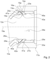
- the S-tube 10a has an input 11a and an output 12a offset axially parallel to the input 11a.
- the sludge pumping device includes a plain bearing 43a, which pivotally supports the S-tube 10a.
- the input 11a of the S-tube 10a is offset axially parallel to the bearing axis 19a.
- the outlet 12a of the S-tube 10a is arranged coaxially to the bearing axis 19a.
- the S-tube 10a is also supported at least partially by the actuator system, which has adjusting elements that are provided for pivoting the S-tube 10a about the bearing axis 19a.
- the inlet 11a of the S-tube 10a is intended to be selectively connected to one of the pump cylinders 32a, 33a.
- the thick matter pump device has a spectacle plate 38a with two recesses, which are each associated with one of the pump cylinders 32a, 33a.
- the S-tube 10a is braced between the starting tube section 17a and the spectacle plate 38a.
- the spectacle plate 38a is fixed to the frame. Depending on the switching position, the input 11a of the S-tube 10a is connected to either one or the other recess of the spectacle plate 38a.
- the S-tube 10a is designed in several parts.
- the S-tube 10a has a tube element 29a and a slide ring, not shown in any more detail, which is arranged on the input side and is intended to be displaced on the spectacle plate 38a for switching.
- the slide ring is connected to the tubular element 29a in an axially displaceable manner in relation to the bearing axis 19a.
- the S-tube 10a has a spring element, not shown in detail, which is arranged between the tube element 29a and the slide ring.
- the spring element is provided in particular for a pressure-tight connection of the sliding ring to the spectacle plate 38a.
- the axially displaceable sliding ring which is displaced when the S-tube 10a is switched between the switching positions on the spectacle plate 38a, is intended in particular to compensate for tolerances in the spectacle plate 38a.
- the outlet 12a of the S-tube 10a is intended to be connected to the delivery line 35a.
- the thick matter pumping device has an outlet pipe section 17a, to which the delivery line 35a is connected.
- the outlet pipe section 17a is designed as a component mounted fixed to the frame.
- the delivery line 35a is permanently but detachably connected to the outlet pipe section 17a.
- the outlet pipe section 17a is arranged after the S-pipe 10a along a flow direction 39a, with which the thick matter flows through the S-pipe 10a and the outlet pipe section 17a.
- the S-tube 10a is mounted pivotably about the bearing axis 19a defined by the slide bearing 43a in relation to the outlet tube section 17a.
- the output 12a of the S-tube 10a which is arranged essentially coaxially to the bearing axis 19a, is always connected to the output tube section 17a, regardless of the switching position of the S-tube 10a, ie the thick matter that enters the S-tube via the input 11a Pipe 10a is pushed in, is always conducted into the outlet pipe section 17a and thus into the conveying line 35a, regardless of the switching position of the S-pipe 10a.
- the thick matter pump device has a seal 18a with two sealing surfaces 15a, 16a.
- the first sealing surface 15a is associated with the S-tube 10a.
- the second sealing surface 16a is assigned to the outlet pipe section 17a.
- the sealing surfaces 15a, 16a are intended to be twisted against each other.
- the sealing surfaces 15a, 16a are rotationally symmetrical. In cross-sectional planes perpendicular to the bearing axis 19a, the sealing surfaces 15a, 16a each have a round internal cross section. The sealing surfaces 15a, 16a each form a sliding surface which is in direct contact with the respective other sealing surface 15a, 16a.
- the sealing surfaces 15a, 16a are simultaneously designed as bearing surfaces which are intended to connect the S-pipe 10a and the outlet pipe section 17a to one another in a supported manner.
- the S-tube 10a and the outlet tube section 17a are sealed via the sealing surfaces 15a, 16a designed as bearing surfaces and are simultaneously connected to one another such that they can rotate in opposite directions.
- the S-tube 10a and the outlet tube section 17a are braced against one another in the axial direction.
- a sealing effect, which is provided by the sealing surfaces 15a, 16a designed as bearing surfaces, depends in particular on a clamping force with which the S-pipe 10a and the outlet pipe section 17a are pressed against one another.
- the sealing surfaces 15a, 16a, the sliding bearing 43a and the seal 18a are formed in one piece.
- the connection between the S-pipe 10a and the outlet pipe section 17a is sealed only by the seal 18a, which is formed by means of the two sealing surfaces 15a, 16a.
- An additional sealing element such as in particular an additional sealing ring arranged inside the plain bearing 43a or adjacent to the plain bearing 43a, is dispensed with.
- a bearing surface oriented in the axial direction, such as that formed by the sliding ring on the input side for connection to the spectacle plate 38a, is also dispensed with in this exemplary embodiment.
- the S-pipe 10a and the outlet pipe section 17a each have a surface which forms an inner wall 47, 48a in a partial area, which is provided for guiding the thick substance, and which forms the sealing surfaces 15a, 16a in a further partial area 20a, 23a.
- the inner wall 47a of the S-tube 10a and the inner wall 48a of the outlet tube section 17a each merge directly into the associated sealing surface 15a, 16a.
- the surfaces each have a rounding or an edge.
- the inner wall 47a of the S-tube 10a merges directly into the sealing surface 15a assigned to the S-tube 10a.
- the inner wall 48a of the outlet pipe section 17a merges directly into the sealing surface 16a assigned to the outlet pipe section 17a.
- the S-tube 10a and the starting tube piece 17a have a common contact line running around the bearing axis 19a.
- the contact line is defined as a line with a minimum radius along which the sealing surface 15a associated with the S-tube 10a and the sealing surface 16a associated with the outlet pipe piece 17a touch.
- the inner walls 47a, 48a merge into the corresponding sealing surface 15a, 16a along the contact line. Since the sealing surfaces 15a, 16a are simultaneously designed as bearing surfaces, a sealing plane can be defined by means of the contact line, in which the S-pipe 10a and the outlet pipe section 17a are connected to one another in a sealed manner.
- the starting pipe section 17a like the S-pipe 10a, is designed in several parts and includes a pipe element 30a, which is arranged fixed to the frame in the assembled state.
- the seal 18a has two wear elements 13a, 14a, which each form one of the sealing surfaces 15a, 16a.
- the first wear element 13a is assigned to the S-tube 10a and connected to the tube element 29a of the S-tube 10a.
- the second wearing element 14a is associated with the outlet pipe section 17a and is connected to the pipe element 30a of the S-pipe 10a.
- the wearing elements 13a, 14a are intended to wear during operation.
- the thick matter pumping device includes a wear compensation unit.
- the wear compensation unit is intended to automatically compensate for wear-related changes in size of the wearing elements 13a, 14a.
- the wear element 13a of the S-tube 10a is also designed as a guide ring 26a for forming the plain bearing 43a.
- the wear element 13a and the guide ring 26a are thus formed in one piece.
- the wear element 13a is firmly connected to the tube element 29a of the S-tube 10a.
- the S-tube 10a has a sealing ring 40a.
- the wear element 13a has a recess which is provided for receiving the sealing ring 40a.
- the pipe element 30a of the outlet pipe section 17a is provided in particular for connecting the delivery line 35a.
- the wear element 14a of the outlet pipe section 17a also simultaneously forms a guide ring 27a for forming the plain bearing 43a.
- the wear element 14a of the outlet pipe section 17a is axially displaceable relative to the pipe element 30a of the outlet pipe section 17a along the bearing axis 19a.
- the tubular element 30a is intended to guide the guide ring 27a of the outlet pipe section 17a along the bearing axis 19a provided for the S-pipe 10a.
- the outlet tubular piece 17a has a sealing ring 41a.
- the sealing surfaces 15a, 16a have a radial component and an axial component over their entire extent. Due to the axial component, the sealing surfaces 15a, 16a are intended to provide the sealing effect.
- the axial component of the sealing surfaces 15a, 16a absorbs in particular an axial prestressing force with which the outlet pipe section 17a and the S-pipe 10a are pressed against one another.
- the outlet pipe section 17a and the S-pipe 10a are supported against one another in the axial direction by the axial component.
- the radial component of the sealing surfaces 15a, 16a absorbs the forces acting in the radial direction on the S-tube 10a and supports them against the outlet tube section 17a, which in turn is arranged fixed to the frame. Due to the radial component, the sealing surfaces 16a, 16a are simultaneously designed as bearing surfaces and are intended to arrange the outlet 12a of the S-tube 10a and the outlet pipe section 17a coaxially with the bearing axis 19a.
- the sealing surfaces 15a, 16a are designed as sloping surfaces which simultaneously have the radial component and the axial component.
- the sealing surfaces 15a, 16a have surface normals over their entire area, which enclose an oblique angle with the bearing axis 19a.
- the sealing surfaces 15a, 16a are thus each formed as inclined surfaces in relation to the bearing axis 19a.
- the surfaces enclose approximately the same angle at each point of the respective sealing surface 15a, 16a with the bearing axis 19a.
- the angle that the surface normals of the sealing surface 15a associated with the S-tube 10a form with the bearing axis 19a is 45 degrees at each point.
- the angle which the surface normals of the sealing surface 16a associated with the outlet pipe section 17a form with the bearing axis 19a is 135 degrees at each point.
- the two sealing surfaces 15a, 16a are thus oriented antiparallel to one another at every point.
- the axial component of the sealing surface 15a associated with the S-tube 10a is oriented along the flow direction 39a of the thick matter.
- the axial component of the sealing surface 16a, which is assigned to the outlet pipe section 17a is oriented counter to the direction of flow 39a of the thick substance.
- the sealing surface 15a associated with the S-tube 10a is in the form of a cylindrical cone, the tip of which is directed along the flow direction 39a of the thick matter.
- the sealing surface 16a which is assigned to the outlet pipe section 17a, is designed in the form of a funnel which tapers along the direction of flow 39a.
- the wear compensation unit has a tensioning element 28a which is intended to apply a pretensioning force to the wearing element 14a of the outlet pipe section 17a.
- the clamping element 28a is designed in the illustrated embodiment in the form of a clamping ring.
- the clamping element 28a has a first end with which it is supported against the tubular element 30a of the outlet pipe section 17a and a second end with which it is supported against the wear element 14a.
- the clamping element 28a is made of an elastically deformable material.
- the clamping element 28a is made of a rubber-like material and forms an elastically compressible volume body that completely fills an area between the wear element 14a and the tubular element 30a.
- the clamping element 28a can also be formed by a spring element, for example in the form of a spiral spring or a plate spring.
- the clamping element 28a and the input-side spring element (not shown in detail) generate the clamping force with which the S-tube 10 is clamped between the spectacle plate 38a and the outlet tube section 17a. Due to the additional mounting of the S-tube 10a via the actuator system, the prestressing force generated by the clamping element 28a acts essentially between the wearing elements 13a, 14a. The prestressing force of the spring element, on the other hand, essentially acts on the sealing ring, which is not shown in detail and is arranged on the input side.
- the two pretensioning forces add up to the tensioning force that causes the connection between the spectacle plate 38a and the inlet 11a of the S-tube 10a and the connection between the outlet 12a of the S-tube 10a and the outlet tube piece 17a to be free of play, whereby the Connection to the spectacle plate 38a and the connection to the outlet pipe section 17a is sealed.
- thick material can be pressed between the two sealing surfaces 15a, 16a against the pretensioning force of the tensioning element 28a.
- the seal 18a which is formed by means of the two sealing surfaces 15a, 16a, is open towards an environment.
- a free space 42a remains between the S-tube 10a and the outlet tube piece 17a, which is open towards the environment. Thick matter, which is pressed between the two sealing surfaces 15a, 16a and overcomes the seal 18a, enters this free space 42a.
- the material feed container 31a partially encloses the slide bearing 43a and thus the seal 18a. Relative to a direction of gravity, along which natural gravity acts when the sludge pump is aligned horizontally, the material feed container 31a is arranged below the plain bearing 43a. The free space 42a is open in the direction of the material feed container 31a. Thick material that migrates through the seal 18a thereby falls into the material feed tank 31a.
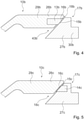
- FIG 4 shows another embodiment of a sludge pumping device with an S-tube 10b and an outlet tube section 17b.
- the S-tube 10b has a tubular element 29b and a guide ring 26b which is formed in one piece with the tubular element 29b and which, in contrast to the exemplary embodiment in FIGS Figures 1 to 3 has a groove and a wear element 13b inserted in the groove.
- the guide ring 26b formed in one piece with the tube element 29b and the wearing element 13b together form a sealing surface 15b assigned to the S-tube 10b.
- the outlet pipe section 17b comprises a pipe element 30b and a guide ring 27b, which, in contrast to the previous exemplary embodiment, are designed in one piece with one another.
- the guide ring 27b of the outlet pipe section 17b forms a sealing surface 16b associated with the outlet pipe section 17b.
- a wear element associated with the outlet pipe section 17b is dispensed with.
- the sealing surfaces 15b, 16b, through which a seal 18b is formed are also oriented differently.
- the wear member 13b associated with the S-tube 10b may be made of a different material than the tube member 29b and the guide ring 26b of the S-tube 10b and/or the guide ring 27b of the exit pipe section 17b.
- the groove into which the wear element 13b is inserted fixes the wear element 13b radially on the outside and radially on the inside, as a result of which the wear element 13b of the S-tube 10b can in particular be made of a softer material than the tube element 29b of the S-tube 10b and/or or the guide ring 27b of the outlet pipe section 17b.
- a sealing effect can thereby be improved.
- a resistance of a plain bearing 43b formed by the seal 18b can also be reduced.
- FIG 5 shows an embodiment of a sludge pumping device with an S-tube 10c and an outlet tube section 17c.
- the S-tube 10c has a tube element 29c, which at the same time forms a guide ring 26c, which has a sealing surface 15c for supporting the S-tube 10c with respect to the outlet tube section 17c.
- the sealing surface 15c associated with the S-tube 10c is thus implemented directly through the tube element 29c.
- the outlet pipe section 17c has a guide ring 27c which has a groove and a wear element 14c inserted into the groove.
- the wearing element 14c which forms a sealing surface 16c associated with the outlet pipe section 17c, can, in accordance with the previous exemplary embodiment, be made of a different material than the guide ring 27c. In particular, it is conceivable to produce the wearing element 14c from a plastic or another non-metallic material.
- the sealing surfaces 15c, 16c form a seal 18c in order to simultaneously provide a contact pressure force for bracing the sealing surfaces 15c, 16c with the wear element 14c.
- the guide ring 27c is according to the embodiment in the Figures 1 to 3 axially displaceable along a bearing axis. Alternatively, however, it is also conceivable to form the guide ring 27c and a tubular element (not shown in detail) of the outlet tubular piece 17c in one piece.
- FIG. 6 shows an embodiment of a sludge pumping device with an S-tube 10d and an outlet pipe section 17d, which essentially corresponds to the embodiment in FIGS Figures 1 to 3 equals.
- the S-tube 10d and the outlet tube section 17d each have a tube element 29d, 30d and a guide ring 26d, 27d.
- the guide rings 26d, 27d which form a plain bearing 43d for mounting the S-tube 10d relative to the outlet tube section 17d, have mutually facing sealing surfaces 15d, 16d for mounting the pivotable S-tube 10d relative to the frame-fixed outlet tube section 17d.
- the S-tube 10d has a connecting element 44d, which connects the guide ring 26d to the tube element 29d.
- the connecting element 44d is designed in the form of a bolt, which is provided in particular to transmit forces directed along a bearing axis.
- the connecting element 44d can also be designed as a locking ring.
- the guide ring 27d of the outlet pipe section 17d has a contact contour for the tensioning element 28d, which is intended to hold the tensioning element 28d in the radial direction to back up.
- the clamping element 28d is in the form of a ring. In the mounted state, the contact contour engages in the clamping element 28d and secures the clamping element 28d radially on the inside.
- the guide ring 27d of the outlet pipe section 17d has a recess made in the sealing surface 16d, which is provided for a wear element 14d.
- the wear element 14d which forms part of the sealing surface 16d and thus also the bearing surface in the assembled state, can be made of different materials.
- FIG 7 shows an embodiment of a sludge pumping device with an S-pipe 10e and an outlet pipe section 17e, which essentially corresponds to the embodiment in FIG figure 6 equals.
- the S-tube 10e and the starting tube section 17e each have a tube element 29e, 30e and a wear element 13e, 14e.
- the wear elements 13e, 14e which at the same time form guide rings 26e, 27e for forming a plain bearing 43e for mounting the S-tube 10e relative to the outlet tube section 17e, have sealing surfaces 15e, 16e facing one another for mounting the pivotable S-tube 10e relative to the frame-fixed outlet tube section 17e on.
- a material feed container 31e is shown, with which the outlet pipe section 17e is firmly connected.
- the material feed container 31e partially encloses the plain bearing 43e.
- the outlet pipe section 17e of the thick matter pumping device has a spacer ring and/or securing ring 46e.
- the spacer and/or securing ring 46e is provided for axially fixing a tensioning element 28e.
- a minimum distance between the wearing element 14e and the tubular element 29e of the outlet tubular piece 17e can be fixed by means of the spacer and/or securing ring 46e.
- the spacer and/or securing ring 46e is designed as a sheet metal element for which different strengths can be provided.
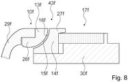
- FIG 8 shows an embodiment of a sludge pumping device with an S-tube 10f and an outlet pipe section 17f, which basically corresponds to the embodiment of FIG characters 1 to 3 equals.
- the S-tube 10f and the starting tube section 17f each have a tube element 29f, 30f and a wear element 13f, 14f.
- the wearing elements 13f, 14f simultaneously form a guide ring 26f, 27f, which form a plain bearing 43f for supporting the S-pipe 10f relative to the outlet pipe section 17f.
- the wearing elements 13f, 14f have mutually facing sealing surfaces 15f, 16f, which are formed in one piece with bearing surfaces for supporting the pivotable S-tube 10f relative to the frame-fixed outlet tube piece 17f.
- the sealing surfaces 15f, 16f are designed as curved surfaces.
- the sealing surface 15f associated with the S-tube 10f has surface normals which enclose an angle of 0 degrees to 90 degrees with a bearing axis.
- the angle which the surface normal has at a point on the sealing surface 15f depends on a radial distance of the point from the sealing surface 15f. The greater the distance between the bearing axis and the point of the sealing surface 15f, the greater the angle between the surface normal and the bearing axis.
- the sealing surface 15f has a constant curvature over its entire radial extent. In the radial direction, the sealing surface 15f is in the form of a segment of a circle.
- the sealing surface 16f assigned to the outlet pipe piece 17f has surface normals which enclose an angle of 180 degrees to 270 degrees with the bearing axis.
- the angle that the surface normal has at a point on the sealing surface 16f also depends on a radial distance of the point from the sealing surface 16f. The greater the distance between the bearing axis and the point of the sealing surface 16f, the greater the angle between the surface normal and the bearing axis.
- the surface normals of the sealing surfaces 15f, 16f are always oriented antiparallel at corresponding points. As a result, the sealing surfaces 15f, 16f always lie flat on top of one another.
- FIG figure 9 shows an embodiment of a sludge pumping device with an S-tube 10g and an outlet pipe section 17g, which is essentially analogous to the embodiment in FIG figure 8 is executed.
- the S-tube 10g and the starting tube section 17g each have a tube element 29g, 30g and a wear element 13g, 14g.
- the wearing elements 13g, 14g which form a seal 18g and a slide bearing 43g for mounting the S-tube 10g relative to the outlet tube section 17g, have sealing surfaces 15g, 16g facing one another, which at the same time serve as bearing surfaces for mounting the pivotable S-tube 10g relative to the frame-fixed output pipe section 17g are formed.
- the sealing surfaces 15g, 16g are designed as curved surfaces.
- the wearing elements 13g, 14g are designed in one piece with guide rings 26g, 27g to form the plain bearing 43g.
- the S-tube 10g has an additional connecting element 44g, which can be designed in the form of a securing bolt or securing ring.
- the connecting element 44g is intended to produce a non-positive and/or positive connection between the tubular element 29g and the .
- the outlet pipe section 17g also has an additional connecting element 45g which is intended to connect the wear element 14g of the outlet pipe section 17g to the pipe element 30g of the outlet pipe section 17g.
- the connecting element 45g which can be designed in the form of a bolt or ring, is provided to connect the wearing element 14g and the tubular element 30g to one another so that they can be slid axially relative to one another.
- a sealing ring 40g, 41g is provided between the wearing elements 13g, 14g and the tube elements 29g, 30g.
- FIG 10 shows a further exemplary embodiment of a thick matter pumping device with an S-pipe 10h and an outlet pipe section 17h.
- the S-tube 10h and the starting tube section 17h each have a tube element 29h, 30h and a wear element 13h, 14h.
- the wearing elements 13h, 14h which at the same time form guide rings 26h, 27h for a plain bearing 43h for mounting the S-tube 10h relative to the outlet tube section 17h, have mutually facing sealing surfaces 15h, 16 for mounting the pivotable S-tube 10h relative to the frame-fixed outlet tube section 17h .
- the sealing surface 15h associated with the S-tube 10h which is formed entirely by the one-piece wear element 13h of the S-tube 10h, is divided into subregions 20h, 21h, 22h, in which it alternately has a radial component and an axial component.
- the sealing surface 15h has surface normals which are oriented parallel to the bearing axis.
- the sealing surface 15h has surface normals which are oriented perpendicular to the bearing axis.
- the sealing surface 15h has surface normals which are again oriented parallel to the bearing axis.
- the sealing surface 15h faces outwards in relation to the bearing axis.
- the sealing surface 16h associated with the outlet pipe section 17h which is formed entirely by the one-piece wear element 14h of the outlet pipe section 17h, is also divided into three subregions 23h, 24h, 25h, in which it alternately has a radial component and an axial component.
- the sealing surface 16h In the radially inner partial area 24h, the sealing surface 16h has surface normals which are oriented antiparallel to the bearing axis.
- the sealing surface 16h In the adjoining central partial area 24h, the sealing surface 16h has surface normals which are oriented perpendicular to the bearing axis and radially inwards.
- the sealing surface 16h In the radially outer portion 25h, the sealing surface 16h has surface normals which are again oriented antiparallel to the bearing axis.
- FIG 11 shows an embodiment of a sludge pumping device with an S-pipe 10i and an outlet pipe section 17i, which essentially corresponds to the embodiment in FIG figure 10 equals.
- the S-tube 10i has only one guide ring 26i.
- the starting pipe section 17i has a pipe element 30i and a wear element 14i.
- the wearing element 14i which is axially displaceable relative to the tubular element 30i, simultaneously forms a guide ring 27i for a slide bearing 43i for supporting the S-tube 10i in relation to the outlet tube piece 17i.
- Mutually facing sealing surfaces 15i, 16i for mounting the pivotable S-tube 10i relative to the frame-fixed outlet tube piece 17i are each divided into partial areas 20i, 23i, in which they only have an axial component, and partial areas 21i, 24i, in which they only have a radial component. divided.
- the sealing surface 15i assigned to the S-tube 10i is partially formed by the tube element 29i and partially by the guide ring 26i.
- the partial area 20i of the sealing surface 15i, in which the sealing surface 15i only has an axial component, is partially formed by the tubular element 29i and partially by the guide ring 26i.
- the partial area 21i of the sealing surface 15i, in which the sealing surface 15i only has a radial component, is formed entirely by the guide ring 26i.
- the guide ring 26i is thus provided for absorbing radially acting forces.
- a sealing effect is provided by the tube element 29i and the guide ring 26i of the S-tube 10i.
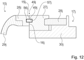
- FIG figure 12 shows a further exemplary embodiment of a sludge pumping device with an S-pipe 10j and an outlet pipe section 17j, which essentially corresponds to the exemplary embodiment in FIG figure 10 equals.
- the S-tube 10j and the outlet tube section 17j each have a tube element 29j, 30j and a guide ring 26j, 27j.
- the guide rings 26j, 27j have mutually facing flat sealing surfaces 15j, 16j.
- the thick matter pumping device has a slide bearing 43j, which supports the S-tube 10j and the outlet tube section 17j against one another.
- the guide rings 26j, 27j each have a groove 56j, 57j on the side facing the sealing surfaces 15j, 16j.
- the sliding bearing 43j has a guide element 49j which is arranged within the grooves 56j, 57j.
- the guide element 49j is provided for absorbing radially acting forces.
- the guide element 49j is designed as an additional wear element.
- the guide element 49j is designed as a steel ring. It is conceivable that the steel ring has slots and/or recesses.
- the sealing surfaces 15j, 16j, the grooves 56j, 57j and the guide element 49j together form the slide bearing 43j for supporting the pivotable S-tube 10j in relation to the starting tube piece 17j which is fixed to the frame.
- FIG 13 another embodiment of the invention is shown.
- the exemplary embodiment essentially corresponds to the exemplary embodiment in FIG figure 12 .
- a sludge pumping device has an S-pipe 10k and an outlet pipe section 17k.
- the S-tube 10k and the outlet tube section 17k have tube elements 29k, 30k and guide rings 26k, 27k on.
- the guide rings 26k, 27k have flat sealing surfaces 15k, 16k facing one another.
- the thick matter pumping device has a slide bearing 43k, which supports the S-tube 10k and the outlet tube piece 17k against one another.
- the tubular element 29k has four recesses 50k on a side facing the guide ring 26k.
- the recesses 50k are arranged mirror-symmetrically to one another.
- the recesses 50k are designed as blind holes.
- the guide ring 26k has four through openings 51k.
- the through openings 51k are arranged congruently with the recesses 50k.
- the guide ring 27k has a groove 57k on a side facing the guide ring 26k.
- the recesses 50k, the through openings 51k and the groove 57k are intended to accommodate four guide elements 49k.
- the guide elements 49k are designed as wear bolts.
- the guide ring 27k absorbs radially acting forces from the tubular element 29k by means of the groove 57k.
- the guide rings 26k, 27k, the sealing surfaces 15k, 16k, the groove 57k and the guide elements 49k form the plain bearing 43k, which serves to support the pivotable S-tube 10k relative to the starting tube piece 17k fixed to the frame.
- FIG 14 Another embodiment according to the embodiment in figure 10 is in figure 14 shown.
- a sludge pumping device with an S-pipe 10l and an outlet pipe section 17l is shown.
- Guide rings 26l, 27l are arranged coaxially to one another.
- Flat sealing surfaces 15i, 16l of the guide rings 26l, 27l are arranged opposite one another.
- the S-pipe 10l and the outlet pipe section 17l have an additional wear element 52l.
- the additional wear element 52l is attached to a tubular element 30l.
- the additional wear element 52l is welded to the tubular element 30l.
- the additional wearing element can also be connected to the tubular element in any way that appears sensible to a person skilled in the art.
- the additional wear element 52l has a rectangular cross section.
- the additional wear element 52l serves to absorb radially acting forces emanating from the tubular element 29l in one or more partial areas.
- figure 15 shows an embodiment of a sludge pumping device with an S-pipe 10m and an outlet pipe section 17m, which is essentially analogous to the embodiment in FIG figure 10 is trained.
- the tubular element 29m has a groove 53m on a side facing the guide ring 26m.
- the guide ring 26m forms a pin 54m on a side facing the tubular element 29m. In an assembled state, the pin 54m engages in the groove 53m.
- the tubular element 29m and the guide ring 26m are connected to one another by means of a pin connection.
- Flat sealing surfaces 15m, 16m of the guide ring 26m and the guide ring 27m are arranged opposite one another.
- An additional wear element 52m is arranged on faces of the guide rings 26m, 27m and the tube element 30m.
- the additional wear element 52m is partially arranged between the guide ring 27m and the tubular element 30m.
- the additional wear element 52m has an L-shaped cross-section with two legs, only one of the legs being arranged between the guide ring 27m and the tubular element 30m. The other leg is intended in particular to limit an insertion depth of the guide ring 27m into the tubular element 30m.
- the additional wear element 52m is attached to the tubular element 30m in order to absorb radially acting forces of the tubular element 29m in one or more partial areas.
- FIG figure 16 shows an embodiment of a sludge pumping device with an S-tube 10n and an outlet tube section 17n, which essentially corresponds to the embodiment in FIG figure 10 equals.
- the S-tube 10n and the outlet tube section 17n each have a tube element 29n, 30n and a guide ring 26n, 27n.
- the guide rings 26n, 27n which form a plain bearing 43n for mounting the S-tube 10n relative to the outlet tube section 17n, have mutually facing sealing surfaces 15n, 16n for mounting the pivotable S-tube 10n relative to the frame-fixed outlet tube section 17n.
- the sealing surface 15n associated with the S-tube 10n is formed partially by the tube element 29n and partially by the guide ring 26n.
- An additional wear element 52n is arranged on the tube element 30n.
- the additional wear element 52n is as a Wear roller formed.
- the additional wear element 52n is rotatably mounted by means of a pin 55n which is connected to the tubular element 30n.
- the tube element 30n has four additional wear elements 52n.
- the additional wear elements 52n are intended to absorb radially acting forces of the tubular element 29n.
- the additional wear member 52n may be attached to the tubular member 30n in any manner deemed appropriate by a person skilled in the art. It is also conceivable to deviate from the number of additional wearing elements present in this exemplary embodiment in order to fulfill a task described here.
Landscapes
- Engineering & Computer Science (AREA)
- Mechanical Engineering (AREA)
- General Engineering & Computer Science (AREA)
- Structures Of Non-Positive Displacement Pumps (AREA)
- Reciprocating Pumps (AREA)
- Quick-Acting Or Multi-Walled Pipe Joints (AREA)
Description
- Die Erfindung betrifft eine Dickstoffpumpvorrichtung zur Ausbildung einer Dickstoffpumpe, insbesondere fahrbare Dickstoffpumpe, wie sie beispielsweise zum Pumpen von Beton verwendet werden kann.
- Es ist bereits eine Dickstoffpumpvorrichtung für eine fahrbare Dickstoffpumpe mit einem S-Rohr und mit einem an das S-Rohr anschließenden Ausgangsrohrstück, zu dem das S-Rohr schwenkbar angeordnet ist, bekannt.
- Beispielsweise offenbart die
EP 0 052 192 A1 eine Vorrichtung an Betonpumpen, bestehend aus zwei Pumpzylindern und einem Abförderrohr, wobei ein schwenkbarer, einen Rohrkanal aufweisenden Steuerschieber (welche zusammen das S-Rohr (10) der vorliegenden Erfindung bilden,) abwechselnd einen der Pumpzylinder an das Abförderrohr anschließt, mit einer abdichtenden und Längenänderungen ausgleichenden Einrichtung an den Anschlussstellen des Rohrkanals. - Ferner ist aus der
DE 34 19 832 A1 eine S-Rohrweiche einer Dickstoff, insbesondere Beton, fördernden Doppelkolbenpumpe bekannt. Gemäß der Erfindung erfolgt der Anschluss der Förderleitung mittels eines schwenkbar und leicht abbaubar angeordneten Übergangsstücks, mittels dessen das Nachstellen einer in die Rückwand des Fülltrichters eingesetzten, gegen eine am Ende des Schwenkrohrs angeordnete Verschleißplatte anliegende Dichtung erfolgen kann und dass das Auswechseln dieser Dichtung erleichtert. - Druckschrift
WO 8001594 A1 - Zudem offenbart das
US-Patent Nr. 51 80 294 eine Druckabdichtungsvorrichtung für die Verwendung in einer Betonpumpe mit einer Vielzahl von Pumpenzylindern, die abwechselnd geladen und entladen werden, wobei jeder dieser Zylinder eine Öffnung aufweist, durch die der Beton ausgetragen wird, und ein verschwenkbar montiertes Schwingrohr vorgesehen ist, welches ein Einlassende besitzt, welches in Deckung und außer Deckung mit jeder der Öffnung bewegt werden kann, und zwar abwechselnd, um also den Beton, der aus demselben abgegeben wird, aufzunehmen. Allgemein gesagt umfasst die Druckabdichtungsvorrichtung eine Lageranordnung, um schwenkbar ein Abgabeende des Schwingrohres zu haltern, wobei diese einen ersten Lagerabschnitt umfasst, der an einer Halterungskonstruktion montiert ist, und einen zweiten Lagerungsabschnitt umfasst, der an dem Schwingrohr montiert ist, wobei der zweite Lagerungsabschnitt eine Druckfläche aufweist, die an demselben ausgebildet ist, um eine Kraft auf zunehmen, die zu dem Einlassende des Schwingrohres hin gerichtet verläuft. - Aus der
DE 33 47 288 A1 ist eine Zweizylinder-Kolbenpumpe zur Förderung von Dickstoffen bekannt, die ein zu seinem förderleitungsseitigen Ende hin sich verjüngendes Schwenkrohr aufweist. Diese Konstruktion ermöglicht es, Anlagerungen am förderzylinderseitigen Ende des Schwenkrohrs zu vermeiden bzw. abzulösen. - Die Aufgabe der vorliegenden Erfindung besteht insbesondere darin, eine einfach zu wartende Dickstoffpumpvorrichtung mit einer hohen Betriebssicherheit bereitzustellen. Die Aufgabe wird erfindungsgemäß durch die Merkmale des Patentanspruchs 1 gelöst, während vorteilhafte Ausgestaltungen und Weiterbildungen der Erfindung den Unteransprüchen entnommen werden können.
- Die Erfindung geht aus von einer Dickstoffpumpvorrichtung, insbesondere für eine fahrbare Dickstoffpumpe, mit einem zumindest schwenkbaren S-Rohr, das einen Eingang und einen achsparallel zu dem Eingang versetzten Ausgang aufweist.
- Erfindungsgemäß ist ein an das S-Rohr anschließendes Ausgangsrohrstück vorgesehen, an welches eine Förderleitung angebunden ist, wobei das Ausgangsrohrstück dazu vorgesehen ist, mit dem Ausgang des S-Rohrs verbunden zu werden, und mit zumindest einer Dichtung, die zumindest zwei gegeneinander verdrehbare Dichtflächen aufweist, welche dazu vorgesehen sind, eine Verbindung zwischen dem S-Rohr und dem Ausgangsrohrstück abzudichtenDie Dichtung weist erfindungsgemäß zumindest ein Verschleißelement auf, das eine der Dichtflächen ausbildet. Indem für die Dickstoffpumpvorrichtung ein Verschleißelement vorgesehen wird, kann dieses für einen einfachen Austausch vorgesehen werden, wodurch eine Wartung der Dickstoffpumpvorrichtung vereinfacht werden kann. Durch Ausbildung von einer oder mehreren Dichtflächen durch jeweils ein Verschleißelement kann insbesondere die Dichtung gezielt für einen Verschleiß vorgesehen werden. Mittels aneinander liegenden Dichtflächen kann eine gute Dichtwirkung erzielt werden. Indem das Verschleißelement die Dichtflächen ausbildet, kann eine gute Dichtwirkung erreicht und gleichzeitig eine einfache Wartung ermöglicht werden, wodurch insgesamt eine einfach zu wartende Dickstoffpumpvorrichtung mit einer hohen Betriebssicherheit bereitgestellt werde kann. Unter "Dichtflächen" sollen in diesem Zusammenhang insbesondere eine dem S-Rohr zugeordnete Dichtfläche und eine dem Ausgangsrohrstück zugeordnete Dichtfläche verstanden werden, die dazu vorgesehen sind, durch Anlage aneinander eine Dichtwirkung zwischen dem Ausgangsrohrstück und dem gegenüber den Ausgangsrohrstück verschwenkbar gelagerten S-Rohr bereitzustellen. Unter einer "Dichtfläche" soll dabei insbesondere eine Fläche mit einer radialen Erstreckung von zumindest 2 mm, vorzugsweise zumindest 5 mm und besonders bevorzugt von zumindest 10 mm verstanden werden. Unter "radial" und "axial" sollen dabei hier und im Folgenden insbesondere Richtungsangaben in Bezug auf eine Lagerachse des schwenkbaren S-Rohrs verstanden werden. Unter einer "radialen Erstreckung" soll insbesondere eine Erstreckung der Dichtfläche in einer Projektionsebene senkrecht zu der Lagerachse verstanden werden". Unter einem "Verschleißelement" soll in diesem Zusammenhang insbesondere ein Bauteil verstanden werden, das beispielsweise aufgrund seiner Materialeigenschaften, insbesondere aber in Hinblick auf seine Demontierbarkeit, gezielt für einen Verschleiß vorgesehen ist. Beispielsweise kann das Verschleißelement eine Markierung aufweisen, die dazu vorgesehen ist, eine Verschieißgrenze festzulegen. Denkbar ist beispielsweise auch, dass das Verschleißelement aus einem weicheren Material ist als ein Bauteil, welches die andere Dichtfläche aufweist. Ebenfalls vorteilhaft ist, wenn das Verschleißelement konstruktiv einfach ausgestaltet ist, beispielsweise als Umformteil oder in einem spanabhebenden Verfahren herstellbar, um das Verschleißelement kostengünstig herstellen zu können. Unter "vorgesehen" soll insbesondere speziell ausgelegt und/oder ausgestattet verstanden werden. Darunter, dass ein Objekt zu einer bestimmten Funktion vorgesehen ist, soll insbesondere verstanden werden, dass das Objekt diese bestimmte Funktion in zumindest einem Anwendungs- und/oder Betriebszustand erfüllt und/oder ausführt.
- Weiter wird vorgeschlagen, dass die Dickstoffpumpvorrichtung eine Verschleißausgleichseinheit aufweist, die dazu vorgesehen ist, einen Verschleiß des Verschleißelements während eines Betriebs zu kompensieren. Dadurch kann eine Funktionsfähigkeit der Dickstoffpumpvorrichtung unabhängig von einem Verschleißgrad des Verschleißelements sichergestellt werden, wodurch die Betriebssicherheit weiter erhöht werden kann. Insbesondere wenn die Verschleißausgleichseinheit selbstständig arbeitet, kann zudem ein Betriebskomfort erhöht werden. Unter einer "Verschleißausgleichseinheit" soll dabei insbesondere eine Einheit verstanden werden, die dazu vorgesehen ist, eine Änderung von Abmessungen des Verschleißelements zu kompensieren.
- Vorzugsweise ist zumindest das Verschleißelement entlang einer für das S-Rohr vorgesehenen Lagerachse axial verschiebbar. Dadurch kann eine Verschleißausgleichseinheit einfach realisiert werden, insbesondere wenn das Verschleißelement derart ausgelegt ist, dass sich mit zunehmendem Verschleiß insbesondere axiale Abmessungen des Verschleißelements ändern. Unter "axial verschiebbar" soll dabei insbesondere verstanden werden, dass das Verschleißelement gegenüber einem rahmenfest angeordneten Teil des Ausgangsrohrstücks entlang der Lagerachse axial verschiebbar angeordnet ist.
- In einer besonders vorteilhaften Ausgestaltung wird vorgeschlagen, dass die Verschleißausgleichseinheit zumindest ein Spannelement aufweist, das dazu vorgesehen ist, eine Anpresskraft zur Verspannung der Dichtflächen gegeneinander bereitzustellen. Indem das Spannelement dazu vorgesehen ist, bei einer Montage der Dickstoffpumpvorrichtung vorgespannt zu werden, kann eine mechanisch selbstständig nachstellende Verschleißausgleichseinheit realisiert werden. Durch ein Spannelement kann somit die Verschleißausgleichseinheit konstruktiv einfach ausgestaltet werden.
- Erfindungsgemäß ist vorgesehen, dass die Dickstoffpumpvorrichtung zumindest einen Führungsring zur Ausbildung eines Gleitlagers, das zur Lagerung des S-Rohrs gegenüber dem Ausgangsrohrstück vorgesehen ist, aufweist. Dadurch kann eine Lagerung für das S-Rohr konstruktiv einfach realisiert werden, da mittels eines Führungsrings eine konstruktiv einfache Lagerung realisiert werden kann. Zudem kann dadurch eine einfache Ausgestaltung der Dichtung realisiert werden. Unter einem "Führungsring" soll dabei insbesondere ein ringförmiges Bauteil verstanden werden, das erfindungsgemäß zumindest eine Lagerfläche zur Ausbildung des Gleitlagers aufweist. Unter einer Lagerfläche soll in diesem Zusammenhang eine Fläche verstanden zu werden, die zumindest eine radiale Komponente aufweist und die dazu vorgesehen ist, in radialer Richtung wirkende Lagerkräfte aufzunehmen. Unter einer "radialen Komponente" soll dabei insbesondere verstanden werden, dass die Lagerfläche in zumindest einem Punkt eine Oberflächennormale aufweist, deren Komponente in radialer Richtung größer als Null ist. Ergänzend dazu soll unter einer "axialen Komponente" insbesondere verstanden werden, dass die Lagerfläche in zumindest einem Punkt eine Oberflächennormale aufweist, deren Komponente in axialer Richtung größer als Null ist.
- Besonders vorteilhaft weist das Ausgangsrohrstück ein Rohrelement auf und das Spannelement ist mit einem Ende gegen den Führungsring und mit einem Ende gegen das Rohrelement des Ausgangsrohrstücks abgestützt. Dadurch kann die Verschleißausgleichseinheit konstruktiv besonders einfach ausgestaltet werden, da eine Abstützung des Spannelements gegenüber dem rahmenfest angeordneten Rohrelement einfach realisiert werden kann. Insbesondere ist es in einer solchen Ausgestaltung besonders einfach möglich, das Spannelement als elastisch verformbares Bauteil, wie beispielsweise als Federelement, auszubilden. Alternativ oder zusätzliches ist es auch denkbar dass die Dickstoffpumpvorrichtung zumindest ein mit dem Führungsring einstückig ausgeführtes Rohrelement aufweist, das dem S-Rohr oder dem Ausgangsrohrstück zugeordnet ist.
- In einer Weiterbildung wird vorgeschlagen, dass der Führungsring und das Verschleißelement zumindest teilweise einstückig ausgebildet sind. Dadurch kann das Verschleißelement konstruktiv einfach ausgebildet werden, da ein Ring einfach herstellbar ist. Zudem kann, indem der Führungsring gleichzeitig die Dichtflächen und die Lagerflächen ausbildet, auf zusätzliche Bauteile verzichtet werden, wodurch die konstruktive Ausgestaltung ebenfalls vereinfacht werden kann.
- Alternativ ist es aber auch denkbar, dass der Führungsring eine Nut zur Aufnahme des Verschleißelements aufweist. Dadurch kann eine Aufnahme für das Verschleißelement bereitgestellt werden, die das Verschleißelement auch in radialer Richtung sichert. Dadurch kann das Verschleißelement besonders gut abgestützt werden, wodurch es möglich ist, das Verschleißelement aus Materialen auszubilden, deren Festigkeit zu gering ist, um den Führungsring auszubilden.
- Erfindungsgemäß weist der Führungsring zumindest eine zur Ausbildung des Gleitlagers vorgesehene Lagerfläche auf, die zumindest teilweise einstückig mit einer der Dichtflächen ausgeführt ist. Indem ein Teilbereich einer Oberfläche des Führungsring gleichzeitig die Lagerfläche und die Dichtfläche ausbildet, welche dem S-Rohr oder dem Ausgangsrohrstück zugeordnet ist, kann eine Lagerung des S-Rohrs gegenüber dem Ausgangsrohrstück vereinfacht werden, ohne dass gleichzeitig eine Dichtung vorgesehen werden muss, welche die Lagerung von einen Innenraum zur Führung des Dickstoff trennt. Dadurch kann eine schwenkbare Verbindung zwischen dem S-Rohr und dem Ausgangsrohrstück konstruktiv einfach ausgestaltet werden, ohne dass eine aufwendige Lagerung und eine getrennt davon vorgesehen Dichtung notwendig sind.
- Vorzugsweise weisen die Dichtflächen zur Ausbildung des Gleitlagers in zumindest einem Teilbereich eine radiale Komponente und in zumindest einem Teilbereich eine axiale Komponente auf. Dadurch können radiale Kräfte, die insbesondere zur Lagerung notwendig sind, und axiale Kräfte, die zur dichten Verbindung notwendig sind, gleichzeitig übertragen werden, wodurch eine stabile Lagerung bei gleichzeitig guter Dichtwirkung erreicht werden kann. Die Dichtflächen können dabei jeweils zumindest teilweise als Schrägflächen ausgebildet sein, jeweils zumindest eine Stufe aufweisen und/oder zumindest teilweise als gekrümmte Flächen ausgebildet sein.
- Weiter wird vorgeschlagen, dass die Dickstoffpumpvorrichtung einen Materialaufgabebehälter aufweist, der dazu vorgesehen ist, über die Dichtung austretendes Material aufzufangen. Dadurch kann Dickstoff, der die Dichtung durchdringt, beispielsweise bei einer Beschädigung oder Überbelastung der Dichtflächen, einfach wieder aufgefangen werden, wodurch auf eine Kapselung des Lagers, welche einen Austritt von Dickstoff verhindert, verzichtet werden kann.
- Zudem wird eine Dickstoffpumpe, insbesondere fahrbare Dickstoffpumpe, mit einer erfindungsgemäßen Dickstoffpumpvorrichtung vorgeschlagen.
- Weitere Vorteile ergeben sich aus der folgenden Zeichnungsbeschreibung. In den Zeichnungen sind neun Ausführungsbeispiele der Erfindung dargestellt. Die Zeichnungen, die Beschreibung und die Ansprüche enthalten zahlreiche Merkmale in Kombination. Der Fachmann wird die Merkmale zweckmäßigerweise auch einzeln betrachten und zu sinnvollen weiteren Kombinationen zusammenfassen.
- Es zeigen:
- Fig. 1
- eine schematische Darstellung einer Dickstoffpumpe,
- Fig. 2
- eine Dickstoffpumpvorrichtung der Dickstoffpumpe,
- Fig. 3
- ein S-Rohr der Dickstoffpumpvorrichtung,
- Fig. 4
- eine zweite Ausgestaltung einer Lagerung zwischen einem S-Rohr und einem Ausgangsrohrstück einer Dickstoffpumpvorrichtung,
- Fig. 5
- eine dritte Ausgestaltung einer Lagerung zwischen einem S-Rohr und einem Ausgangsrohrstück einer Dickstoffpumpvorrichtung,
- Fig. 6
- eine vierte Ausgestaltung einer Lagerung zwischen einem S-Rohr und einem Ausgangsrohrstück einer Dickstoffpumpvorrichtung,
- Fig. 7
- eine fünfte Ausgestaltung einer Lagerung zwischen einem S-Rohr und einem Ausgangsrohrstück einer Dickstoffpumpvorrichtung,
- Fig. 8
- eine sechste Ausgestaltung einer Lagerung zwischen einem S-Rohr und einem Ausgangsrohrstück einer Dickstoffpumpvorrichtung,
- Fig. 9
- eine siebte Ausgestaltung einer Lagerung zwischen einem S-Rohr und einem Ausgangsrohrstück einer Dickstoffpumpvorrichtung,
- Fig. 10
- eine achte Ausgestaltung einer Lagerung zwischen einem S-Rohr und einem Ausgangsrohrstück einer Dickstoffpumpvorrichtung und
- Fig. 11
- eine neunte Ausgestaltung einer Lagerung zwischen einem S-Rohr und einem Ausgangsrohrstück einer Dickstoffpumpvorrichtung.
- Fig. 12
- eine zehnte Ausgestaltung einer Lagerung zwischen einem S-Rohr und einem Ausgangsrohrstück einer Dickstoffpumpvorrichtung,
- Fig. 13
- eine elfte Ausgestaltung einer Lagerung zwischen einem S-Rohr und einem Ausgangsrohrstück einer Dickstoffpumpvorrichtung,
- Fig. 14
- eine zwölfte Ausgestaltung einer Lagerung zwischen einem S-Rohr und einem Ausgangsrohrstück einer Dickstoffpumpvorrichtung,
- Fig. 15
- eine dreizehnte Ausgestaltung einer Lagerung zwischen einem S-Rohr und einem Ausgangsrohrstück einer Dickstoffpumpvorrichtung,
- Fig. 16
- eine vierzehnte Ausgestaltung einer Lagerung zwischen einem S-Rohr und einem Ausgangsrohrstück einer Dickstoffpumpvorrichtung.
- Die
Figuren 1 und2 zeigen eine Dickstoffpumpe mit einer Dickstoffpumpvorrichtung, die zur Montage auf einem Nutzfahrzeug vorgesehen ist. Die Dickstoffpumpe bildet eine fahrbare Dickstoffpumpe aus. Die Dickstoffpumpe umfasst einen Materialaufgabebehälter 31a zur Zuführung von Dickstoff, zwei Pumpzylinder 32a, 33a zur Erzeugung einer Pumpleistung, die Dickstoffpumpvorrichtung, welche insbesondere eine an die Pumpzylinder 32a, 33a anschließende Rohrweiche 34a aufweist, und eine an die Rohrweiche 34a anschließende Förderleitung 35a zur Förderung des Dickstoffs. - Zum Betrieb insbesondere der Pumpzylinder 32a, 33a und zur Umschaltung der Rohrweiche 34a umfasst die Dickstoffpumpe eine nicht näher dargestellte Aktuatorik. Die Aktuatorik ist für einen gegenläufigen Betrieb der zwei Pumpzylinder 32a, 33a vorgesehen. In einem Pumpbetrieb führt jeweils einer der Pumpzylinder 32a, 33a einen Pumphub aus, während gleichzeitig der andere Pumpzylinder 32a, 33a einen Saughub ausführt. Jeder der Pumpzylinder 32a, 33a weist eine Ein- und Auslassöffnung 36a, 37a auf, über die der Dickstoff während des Saughubs in den entsprechenden Pumpzylinder 32a, 33a eingesaugt und während des Pumphubs wieder aus dem Pumpzylinder 32a, 33a herausgepresst wird. Die Pumpzylinder 32a, 33a sind achsparallel zueinander angeordnet.
- Die Rohrweiche 34a ist dazu vorgesehen, die Pumpzylinder 32a, 33a wechselweise mit der Förderleitung 35a zu verbinden. Die Rohrweiche 34a weist ein S-Rohr 10a auf, das um eine Lagerachse 19a schwenkbar angeordnet ist. Das S-Rohr 10a weist zwei Schaltstellungen auf. In der ersten Schaltstellung verbindet das S-Rohr 10a die Ein- und Auslassöffnung 36a des ersten Pumpzylinders 32a mit der Förderleitung 35a. In der zweiten Schaltstellung verbindet das S-Rohr 10a die Ein- und Auslassöffnung 37a des zweiten Pumpzylinders 33a mit der Förderleitung 35a. Die Ein- und Auslassöffnung 36a, 37a des jeweils anderen Pumpzylinders 32a, 33a ist dabei mit dem Materialaufgabebehälter 31a verbunden, wodurch je nach Schaltstellung der eine Pumpzylinder 32a, 33a mit der Förderleitung 35a und der andere Pumpzylinder 32a, 33a mit dem Materialaufgabebehälter 31a verbunden ist. Die Aktuatorik ist dazu vorgehen, die Rohrweiche 34a in Abhängigkeit einer Bewegung der Pumpzylinder 32a, 33a anzusteuern.
- Das S-Rohr 10a weist einen Eingang 11a und einen achsparallel zu dem Eingang 11a versetzten Ausgang 12a auf. Zur Lagerung des S-Rohrs 10a umfasst die Dickstoffpumpvorrichtung ein Gleitlager 43a, das das S-Rohr 10a schwenkbar lagert. Der Eingang 11a des S-Rohrs 10a ist achsparallel versetzt zu der Lagerachse 19a angeordnet. Der Ausgang 12a des S-Rohrs 10a ist koaxial zu der Lagerachse 19a angeordnet. Eine Lagerung des S-Rohrs 10a erfolgt zudem zumindest teilweise über die Akuatorik, die Stellelemente aufweist, die dazu vorgesehen sind, das S-Rohr 10a um die Lagerachse 19a zu verschwenken.
- Der Eingang 11a des S-Rohrs 10a ist dazu vorgesehen, wahlweise mit einem der Pumpzylinder 32a, 33a verbunden zu werden. Zur Verbindung mit den Pumpzylindern 32a, 33a weist die Dickstoffpumpvorrichtung eine Brillenplatte 38a mit zwei Aussparungen auf, welche jeweils einem der Pumpzylinder 32a, 33a zugeordnet sind. Das S-Rohr 10a ist zwischen dem Ausgangsrohrstück 17a und der Brillenplatte 38a verspannt. Die Brillenplatte 38a ist rahmenfest angeordnet. In Abhängigkeit der Schaltstellung ist der Eingang 11a des S-Rohrs 10a entweder mit der einen oder der anderen Aussparung der Brillenplatte 38a verbunden.
- Das S-Rohr 10a ist mehrteilig ausgebildet. Das S-Rohr 10a weist ein Rohrelement 29a und einen nicht näher dargestellten eingangsseitig angeordneten Gleitring auf, der dazu vorgesehen ist, zur Umschaltung auf der Brillenplatte 38a verschoben zu werden. Zum Ausgleich von Toleranzen und/oder Verschleiß ist der Gleitring, bezogen auf die Lagerachse 19a, axial verschiebbar mit dem Rohrelement 29a verbunden. Um den Gleitring mit einer Vorspannkraft zu beaufschlagen, die den Gleitring gegen die Brillenplatte 38a drückt, weist das S-Rohr 10a ein nicht näher dargestelltes Federelement auf, welches zwischen dem Rohrelement 29a und dem Gleitring angeordnet ist. Das Federelement ist insbesondere für eine druckdichte Verbindung des Gleitrings mit der Brillenplatte 38a vorgesehen. Der axial verschiebbare Gleitring, der beim Umschalten des S-Rohrs 10a zwischen den Schaltstellungen auf der Brillenplatte 38a verschoben wird, ist insbesondere dazu vorgesehen, Toleranzen der Brillenplatte 38a auszugleichen.
- Der Ausgang 12a des S-Rohres 10a ist dazu vorgesehen, mit der Förderleitung 35a verbunden zu werden. Zur Verbindung des S-Rohrs 10a mit der Förderleitung 35a weist die Dickstoffpumpvorrichtung ein Ausgangsrohrstück 17a auf, an welches die Förderleitung 35a angebunden ist. Das Ausgangsrohrstück 17a ist als ein rahmenfest moniertes Bauteil ausgebildet. Die Förderleitung 35a ist permanent aber lösbar mit dem Ausgangsrohrstück 17a verbunden. Entlang einer Strömungsrichtung 39a, mit der der Dickstoff durch das S-Rohr 10a und das Ausgangsrohrstück 17a strömt, ist das Ausgangsrohrstück 17a nach dem S-Rohr 10a angeordnet.
- Das S-Rohr 10a ist in Bezug auf Ausgangsrohrstück 17a schwenkbar um die durch das Gleitlager 43a definierte Lagerachse 19a gelagert. Der Ausgang 12a des S-Rohrs 10a, der im Wesentlichen koaxial zu der Lagerachse 19a angeordnet ist, ist unabhängig von der Schaltstellung des S-Rohrs 10a stets mit dem Ausgangsrohrstück 17a verbunden, d.h. der Dickstoff, der über den Eingang 11a in das S-Rohr 10a hineingedrückt wird, wird unabhängig von der Schaltstellung des S-Rohrs 10a stets in das Ausgangsrohrstück 17a und damit in die Förderleitung 35a geleitet.
- Insbesondere beim Umschalten des S-Rohrs 10a zwischen den beiden Schaltstellung, aber auch durch den durch das S-Rohr 10a hindurchströmende Dickstoff, wirken auf das S-Rohr 10a Kräfte, die in Bezug auf die Lagerachse 19a in radialer Richtung gerichtet sind. Das Gleitlager 43a, das zur Aufnahme dieser Kräfte vorgesehen ist, leitet die Kräfte beispielsweise an einen nicht näher dargestellten Rahmen ab.
- Um die schwenkbare Verbindung zwischen dem S-Rohr 10a und dem Ausgangsrohrstück 17a gegenüber einer Umgebung abzudichten, weist die Dickstoffpumpvorrichtung eine Dichtung 18a mit zwei Dichtflächen 15a, 16a auf. Die erste Dichtfläche 15a ist dabei dem S-Rohr 10a zugeordnet. Die zweite Dichtfläche 16a ist dem Ausgangsrohrstück 17a zugeordnet. Die Dichtflächen 15a, 16a sind dazu vorgesehen, gegeneinander verdreht zu werden.
- Bezogen auf die Lagerachse 19a sind die Dichtflächen 15a, 16a rotationssymmetrisch ausgebildet. In Querschnittsebenen senkrecht zu der Lagerachse 19a weisen die Dichtflächen 15a, 16a jeweils einen runden Innenquerschnitt auf. Die Dichtflächen 15a, 16a bilden jeweils eine Gleitfläche aus, welche in direktem Kontakt mit der jeweils anderen Dichtfläche 15a, 16a steht.
- Die Dichtflächen 15a, 16a sind gleichzeitig als Lagerflächen ausgebildet, welche dazu vorgesehen sind, das S-Rohr 10a und das Ausgangsrohrstück 17a gelagert miteinander zu verbinden. Über die als Lagerflächen ausgebildeten Dichtflächen 15a, 16a sind das S-Rohr 10a und das Ausgangsrohrstück 17a gedichtet und gleichzeitig gegeneinander verdrehbar miteinander verbunden. Zur Erzeugung einer Dichtwirkung sind das S-Rohr 10a und das Ausgangsrohrstück 17a in axialer Richtung gegeneinander verspannt. Eine Dichtwirkung, welche durch die als Lagerflächen ausgebildeten Dichtflächen 15a, 16a bereitgestellt wird, hängt dabei insbesondere von einer Spannkraft ab, mit der das S-Rohr 10a und das Ausgangsrohrstück 17a gegeneinander gedrückt werden.
- Durch die einstückig mit den Dichtflächen 15a, 16a ausgebildeten Lagerflächen sind das Gleitlager 43a und die Dichtung 18a einstückig ausgebildet. Die Verbindung zwischen dem S-Rohr 10a und dem Ausgangsrohrstück 17a ist in dem dargestellten Ausführungsbeispiel lediglich durch die Dichtung 18a, welche mittels der beiden Dichtflächen 15a, 16a ausgebildet ist, abgedichtet. Auf ein zusätzliches Dichtelement, wie insbesondere einen innerhalb des Gleitlagers 43a oder benachbart zu dem Gleitlager 43a angeordneten zusätzlichen Dichtring, wird verzichtet. Auf eine in axialer Richtung orientierte Lagerfläche, wie sie der eingangsseitige Gleitring zur Verbindung mit der Brillenplatte 38a ausbildet, wird in diesem Ausführungsbeispiel ebenfalls verzichtet.
- Das S-Rohr 10a und das Ausgangsrohrstück 17a weisen jeweils eine Oberfläche auf, die in einem Teilbereich eine Innenwandung 47, 48a ausbilden, welche zur Führung des Dickstoffs vorgesehen ist, und die in einem weiteren Teilbereich 20a, 23a die Dichtflächen 15a, 16a ausbilden. Die Innenwandung 47a des S-Rohrs 10a und die Innenwandung 48a des Ausgangsrohrstücks 17a gehen dabei jeweils unmittelbar in die zugeordnete Dichtfläche 15a, 16a über. An einem Übergang zwischen der Innenwandung 47a, 48a und der Dichtfläche 15a, 16a weisen die Oberflächen jeweils eine Rundung oder eine Kante auf. An der einen Kante geht die Innenwandung 47a des S-Rohrs 10a unmittelbar in die dem S-Rohr 10a zugeordnete Dichtfläche 15a über. An der anderen Kante geht die Innenwandung 48a des Ausgangsrohrstücks 17a unmittelbar in die dem Ausgangsrohrstück 17a zugeordnete Dichtfläche 16a über.
- Das S-Rohr 10a und das Ausgangsrohrstück 17a weisen eine gemeinsame, die Lagerachse 19a umlaufende Kontaktlinie auf. Die Kontaktlinie ist definiert als eine Linie mit minimalem Radius, entlang der sich die dem S-Rohr 10a zugeordnete Dichtfläche 15a und die dem Ausgangsrohrstück 17a zugeordnete Dichtfläche 16a berühren. Entlang der Kontaktlinie gehen die Innenwandungen 47a, 48a in die entsprechende Dichtfläche 15a, 16a über. Indem die Dichtflächen 15a, 16a gleichzeitig als Lagerflächen ausgebildet sind, ist mittels der Kontaktlinie eine Dichtebene definierbar, in der das S-Rohr 10a und das Ausgangsrohrstück 17a gedichtet miteinander verbunden sind.
- Das Ausgangsrohrstück 17a ist, wie auch das S-Rohr 10a, mehrteilig ausgebildet und umfasst ein Rohrelement 30a, welches in montiertem Zustand rahmenfest angeordnet ist. Die Dichtung 18a weist zur Ausbildung der Dichtflächen 15a, 16a zwei Verschleißelemente 13a, 14a auf, die jeweils eine der Dichtflächen 15a, 16a ausbilden. Das erste Verschleißelement 13a ist dem S-Rohr 10a zugeordnet und mit dem Rohrelement 29a des S-Rohrs 10a verbunden. Das zweite Verschleißelement 14a ist dem Ausgangsrohrstück 17a zugeordnet und mit dem Rohrelement 30a des S-Rohrs 10a verbunden.
- Die Verschleißelemente 13a, 14a sind für einen Verschleiß während des Betriebs vorgesehen. Um einen Verschließ der Verschleißelemente 13a, 14a während eines Betriebs zu kompensieren, umfasst die Dickstoffpumpvorrichtung eine Verschleißausgleichseinheit. Die Verschleißausgleichseinheit ist dazu vorgesehen, verschleißbedingte Größenänderungen der Verschleißelemente 13a, 14a selbstständig auszugleichen.
- Das Verschleißelement 13a des S-Rohrs 10a ist gleichzeitig als ein Führungsring 26a zur Ausbildung des Gleitlagers 43a ausgebildet. Das Verschleißelement 13a und der Führungsring 26a sind damit einstückig ausgebildet. Das Verschleißelement 13a ist fest mit dem Rohrelement 29a des S-Rohrs 10a verbunden. Um das Rohrelement 29a und das Verschleißelement 13a gegeneinander abzudichten, weist das S-Rohr 10a einen Dichtring 40a auf. Das Verschleißelement 13a weist eine Ausnehmung auf, die zur Aufnahme des Dichtrings 40a vorgesehen ist.
- Das Rohrelement 30a des Ausgangsrohrstücks 17a ist insbesondere zur Anbindung der Förderleitung 35a vorgesehen. Das Verschleißelement 14a des Ausgangsrohrstücks 17a bildet ebenfalls gleichzeitig einen Führungsring 27a zur Ausbildung des Gleitlagers 43a aus. Der Verschleißelement 14a des Ausgangsrohrstücks 17a ist gegenüber dem Rohrelement 30a des Ausgangsrohrstücks 17a entlang der Lagerachse 19a axial verschiebbar. Das Rohrelement 30a ist dazu vorgesehen, den Führungsring 27a des Ausgangsrohrstücks 17a entlang der für das S-Rohr 10a vorgesehenen Lagerachse 19a zur führen. Um das Rohrelement 30a und das Verschleißelement 14a gegeneinander abzudichten, weist das Ausgangsrohrstück 17a einen Dichtring 41a auf.
- Zur einstückigen Ausbildung mit den Lagerflächen weisen die Dichtflächen 15a, 16a über ihre gesamte Erstreckung eine radiale Komponente und eine axiale Komponente auf. Durch die axiale Komponente sind die Dichtflächen 15a, 16a dazu vorgesehen, die Dichtwirkung bereitzustellen. Die axiale Komponente der Dichtflächen 15a, 16a nimmt insbesondere eine axiale Vorspannkraft auf, mit welcher das Ausgangsrohrstück 17a und das S-Rohr 10a gegeneinander gepresst sind. Durch die axiale Komponente sind das Ausgangsrohrstück 17a und das S-Rohr 10a in axialer Richtung gegeneinander abgestützt. Die radiale Komponente der Dichtflächen 15a, 16a nimmt die in radialer Richtung auf das S-Rohr 10a wirkenden Kräfte auf und stützt sie gegen das Ausgangsrohrstück 17a ab, welches wiederrum rahmenfest angeordnet ist. Durch die radiale Komponente sind die Dichtflächen 16a, 16a gleichzeitig als Lagerflächen ausgebildet und dazu vorgesehen, den Ausgangs 12a des S-Rohrs 10a und das Ausgangsrohrstück 17a koaxial zu der Lagerachse 19a anzuordnen.
- Die Dichtflächen 15a, 16a sind als Schrägflächen ausgebildet, die gleichzeitig die radiale Komponente und die axiale Komponente aufweisen. Die Dichtflächen 15a, 16a weisen über ihren gesamten Bereich Oberflächennormalen auf, die mit der Lagerachse 19a einen schiefen Winkel einschließen. Die Dichtflächen 15a, 16a sind damit in Bezug auf die Lagerachse 19a jeweils als Schrägflächen ausgebildet. Die Oberflächen schließen in jedem Punkt der jeweiligen Dichtfläche 15a, 16a mit der Lagerachse 19a in etwa den gleichen Winkel ein.
- In dem dargestellten Ausführungsbeispiel beträgt der Winkel, den die Oberflächennormalen der dem S-Rohr 10a zugeordneten Dichtfläche 15a mit der Lagerachse 19a einschließen, in jedem Punkt 45 Grad. Korrespondierend beträgt der Winkel, den die Oberflächennormalen der dem Ausgangsrohrstück 17a zugeordneten Dichtfläche 16a mit der Lagerachse 19a einschließen, in jedem Punkt 135 Grad. Die beiden Dichtflächen 15a, 16a sind damit in jedem Punkt antiparallel zueinander orientiert. Die axiale Komponente der Dichtfläche 15a, die dem S-Rohr 10a zugeordnet ist, ist entlang der Strömungsrichtung 39a des Dickstoffs orientiert. Die axiale Komponente der Dichtfläche 16a, die dem Ausgangsrohrstück 17a zugeordnet ist, ist entgegen der Strömungsrichtung 39a des Dickstoffs orientiert. Die Dichtfläche 15a, die dem S-Rohr 10a zugeordnet ist, ist in Form eines Zylinderkegels ausgebildet, dessen Spitze entlang der Strömungsrichtung 39a des Dickstoffs gerichtet ist. Korrespondierend ist die Dichtfläche 16a, die dem Ausgangsrohrstück 17a zugeordnet ist, in Form eines Trichters ausgebildet, der sich entlang der Strömungsrichtung 39a verjüngt.
- Um die zwei Verschleißelemente 13a, 14a gegeneinander zu verspannen, weist die Verschleißausgleichseinheit ein Spannelement 28a auf, das dazu vorgesehen ist, das Verschleißelement 14a des Ausgangsrohrstücks 17a mit einer Vorspannkraft zu beaufschlagen. Das Spannelement 28a ist in dem dargestellten Ausführungsbeispiel in Form eines Spannrings ausgeführt. Das Spannelement 28a weist ein erstes Ende, mit dem es gegen das Rohrelement 30a des Ausgangsrohrstücks 17a abgestützt ist, und ein zweites Ende, mit dem es gegen das Verschleißelement 14a abgestützt ist, auf.
- Das Spannelement 28a ist aus einem elastisch verformbaren Material ausgebildet. In dem dargestellten Ausführungsbeispiel ist das Spannelement 28a aus einem gummiartigen Material ausgebildet und bildet einen elastisch komprimierbaren Volumenkörper aus, der einen Bereich zwischen dem Verschleißelement 14a und dem Rohrelement 30a vollständig ausfüllt. Alternativ kann das Spannelement 28a aber auch durch ein Federelement ausgebildet sein, beispielsweise in Form einer Spiralfeder oder einer Tellerfeder.
- Das Spannelement 28a und das nicht näher dargestellte eingangsseitige Federelement erzeugen die Spannkraft, mit der das S-Rohr 10 zwischen der Brillenplatte 38a und dem Ausgangsrohrstück 17a verspannt ist. Aufgrund der zusätzlichen Lagerung des S-Rohrs 10a über die Akuatorik wirkt die Vorspannkraft, die das Spannelement 28a erzeugt, im Wesentlichen zwischen den Verschleißelementen 13a, 14a. Die Vorspannkraft des Federelements hingegen wirkt im Wesentlichen auf den nicht näher dargestellten eingangsseitig angeordneten Dichtring. Insgesamt summieren sich die beiden Vorspannkräfte zu der Spannkraft, die bewirkt, dass die Verbindung zwischen der Brillenplatte 38a und dem Eingang 11a des S-Rohrs 10a sowie die Verbindung zwischen dem Ausgang 12a des S-Rohrs 10a und dem Ausgangsrohrstück 17a spielfrei ist, wodurch die Verbindung zu der Brillenplatte 38a und die Verbindung zu dem Ausgangsrohrstück 17a gedichtet ist.
- Grundsätzlich kann bei einer solchen Ausgestaltung gegen die Vorspannkraft des Spannelements 28a Dickstoff zwischen die beiden Dichtflächen 15a, 16a gedrückt werden. Um diesen Dickstoff abzuführen, ist die Dichtung 18a, die mittels der beiden Dichtflächen 15a, 16a ausgebildet ist, in Richtung einer Umgebung offen. Radial außerhalb des Gleitlagers 43a, das durch die zwei Dichtflächen 15a, 16a ausgebildet ist, verbleibt zwischen dem S-Rohr 10a und dem Ausgangsrohrstück 17a ein Freiraum 42a, der in Richtung der Umgebung offen ist. Dickstoff, der zwischen den beiden Dichtflächen 15a, 16a gedrückt wird und die Dichtung 18a überwindet, gelangt in diesen Freiraum 42a.
- Der Materialaufgabebehälter 31a umschließt das Gleitlager 43a und damit die Dichtung 18a teilweise. Bezogen auf eine Schwerkraftrichtung, entlang der bei horizontaler Ausrichtung der Dickstoffpumpe eine natürliche Schwerkraft wirkt, ist der Materialaufgabebehälter 31a unterhalb des Gleitlagers 43a angeordnet. Der Freiraum 42a ist in Richtung des Mate-rialaufgabebehälters 31a geöffnet. Dickstoff, der durch die Dichtung 18a hindurchwandert, fällt dadurch in den Materialaufgabebehälter 31a.
- In den
Figuren 4 bis 16 sind zwölf weitere Ausführungsbeispiele der Erfindung gezeigt. Die nachfolgenden Beschreibungen beschränken sich im Wesentlichen auf die Unterschiede zwischen den Ausführungsbeispielen, wobei bezüglich gleichbleibender Bauteile, Merkmale und Funktionen auf die Beschreibung der anderen Ausführungsbeispiele, insbesondere derFiguren 1 bis 3 , verwiesen werden kann. Zur Unterscheidung der Ausführungsbeispiele ist der Buchstabe a in den Bezugszeichen des Ausführungsbeispiels in denFiguren 1 bis 3 durch die Buchstaben b bis n in den Bezugszeichen der Ausführungsbeispiele derFiguren 4 bis 16 ersetzt. Bezüglich gleich bezeichneter Bauteile, insbesondere in Bezug auf Bauteile mit gleichen Bezugszeichen, kann grundsätzlich auch auf die Zeichnungen und/oder die Beschreibung der anderen Ausführungsbeispiele, insbesondere derFiguren 1 bis 3 , verwiesen werden. -
Figur 4 zeigt ein weiteres Ausführungsbeispiel einer Dickstoffpumpvorrichtung mit einem S-Rohr 10b und einem Ausgangsrohrstück 17b. Das S-Rohr 10b weist ein Rohrelement 29b und einen einstückig mit dem Rohrelement 29b ausgebildetes Führungsring 26b auf, welcher im Unterschied zu dem Ausführungsbeispiel in denFiguren 1 bis 3 eine Nut und ein in die Nut eingesetztes Verschleißelement 13b aufweist. Der einstückig mit dem Rohrelement 29b ausgebildete Führungsring 26b und das Verschleißelement 13b bilden gemeinsam eine dem S-Rohr 10b zugeordnete Dichtfläche 15b aus. - Das Ausgangsrohrstück 17b umfasst ein Rohrelement 30b und einen Führungsring 27b, die im Unterschied zu dem vorangegangenen Ausführungsbeispiel einstückig miteinander ausgeführt sind. Der Führungsring 27b des Ausgangsrohrstücks 17b bildet eine dem Ausgangsrohrstück 17b zugeordnete Dichtfläche 16b aus. Auf ein dem Ausgangsrohrstück 17b zugeordnetes Verschleißelement wird verzichtet. Im Unterschied zu dem vorangegangen Ausführungsbeispiel sind zudem die Dichtflächen 15b, 16b, durch die eine Dichtung 18b ausgebildet wird, anders orientiert.
- In diesem Ausführungsbeispiel kann das Verschleißelement 13b, das dem S-Rohr 10b zugeordnet ist, aus einen anderen Material als das Rohrelement 29b und der Führungsring 26b des S-Rohrs 10b und/oder der Führungsring 27b des Ausgangsrohrstücks 17b hergestellt sein. Die Nut, in die das Verschleißelement 13b eingesetzt ist, fixiert das Verschleißelement 13b in radial außen und radial innen, wodurch das Verschleißelement 13b des S-Rohrs 10b insbesondere aus einem weicheren Material hergestellt sein kann als das Rohrelement 29b des S-Rohrs 10b und/oder der Führungsring 27b des Ausgangsrohrstücks 17b. Dadurch kann eine Dichtwirkung verbessert werden. Grundsätzlich kann aber auch ein Widerstand eines durch die Dichtung 18b ausgebildeten Gleitlagers 43b reduziert werden.
-
Figur 5 zeigt ein Ausführungsbeispiel einer Dickstoffpumpvorrichtung mit einem S-Rohr 10c und einem Ausgangsrohrstück 17c. Das S-Rohr 10c weist ein Rohrelement 29c auf, welches gleichzeitig einen Führungsring 26c ausbildet, der eine Dichtfläche 15c zur Lagerung des S-Rohrs 10c gegenüber dem Ausgangsrohrstück 17c aufweist. Die dem S-Rohr 10c zugeordnete Dichtfläche 15c ist in diesem Ausführungsbeispiel damit direkt durch das Rohrelement 29c ausgeführt. - Das Ausgangsrohrstück 17c weist einen Führungsring 27c auf, der eine Nut und ein in die Nut eingesetztes Verschleißelement 14c aufweist. Das Verschleißelement 14c, welches eine dem Ausgangsrohrstück 17c zugeordnete Dichtfläche 16c ausbildet, kann, entsprechend dem vorangegangenen Ausführungsbeispiel, aus einem anderen Material hergestellt sein als der Führungsring 27c. Insbesondere ist es denkbar, das Verschleißelement 14c aus einem Kunststoff oder einem anderen nichtmetallischen Material herzustellen. Die Dichtflächen 15c, 16c bilden eine Dichtung 18c aus, um mit dem Verschleißelement 14c gleichzeitig eine Anpresskraft zur Verspannung der Dichtflächen 15c, 16c bereit zu stellen. Der Führungsring 27c ist entsprechend dem Ausführungsbeispiel in den
Figuren 1 bis 3 entlang einer Lagerachse axial verschiebbar. Alternativ ist es aber auch denkbar, den Führungsring 27c und ein nicht näher dargestelltes Rohrelement des Ausgangsrohrstücks 17c einstückig auszubilden. -
Figur 6 zeigt ein Ausführungsbeispiel einer Dickstoffpumpvorrichtung mit einem S-Rohr 10d und einem Ausgangsrohrstück 17d, das im Wesentlichen dem Ausführungsbeispiel in denFiguren 1 bis 3 gleicht. Das S-Rohr 10d und das Ausgangsrohrstück 17d weisen jeweils ein Rohrelement 29d, 30d und einen Führungsring 26d, 27d auf. Die Führungsringe 26d, 27d, die ein Gleitlager 43d zur Lagerung des S-Rohrs 10d gegenüber dem Ausgangsrohrstück 17d ausbilden, weisen einander zugewandte Dichtflächen 15d, 16d zur Lagerung des verschwenkbaren S-Rohrs 10d gegenüber dem rahmenfesten Ausgangsrohrstück 17d auf. - Zur Sicherung des Führungsrings 26d weist das S-Rohr 10d ein Verbindungselement 44d auf, das den Führungsring 26d mit dem Rohrelement 29d verbindet. Das Verbindungselement 44d ist in Form eines Bolzens ausgeführt, welcher insbesondere dazu vorgesehen ist, entlang einer Lagerachse gerichtete Kräfte zu übertragen. Grundsätzlich kann das Verbindungselement 44d auch als ein Sicherungsring ausgeführt sein.
- Zur Sicherung eines Spannelements 28d, das dazu vorgesehen ist, den Führungsring 27d des Ausgangsrohrstücks 17d mit einer Vorspannkraft zu beaufschlagen, weist der Führungsring 27d des Ausgangsrohrstücks 17d eine Anlagekontur für das Spannelement 28d auf, die dazu vorgesehen ist, das Spannelement 28d in radialer Richtung zu sichern. Das Spannelement 28d ist in Form eines Rings ausgeführt. Die Anlagekontur greift in montiertem Zustand in das Spannelement 28d ein und sichert das Spannelement 28d radial innen.
- Zusätzlich weist der Führungsring 27d des Ausgangsrohrstücks 17d eine in die Dichtfläche 16d eingebrachte Ausnehmung auf, die für ein Verschleißelement 14d vorgesehen ist. Das Verschleißelement 14d, das in montiertem Zustand einen Tell der Dichtfläche 16d und damit auch der Lagerfläche ausbildet, kann aus unterschiedlichen Materialien ausgebildet sein.
-
Figur 7 zeigt ein Ausführungsbeispiel einer Dickstoffpumpvorrichtung mit einem S-Rohr 10e und einem Ausgangsrohrstück 17e, das im Wesentlichen dem Ausführungsbeispiel inFigur 6 gleicht. Das S-Rohr 10e und das Ausgangsrohrstück 17e weisen jeweils ein Rohrelement 29e, 30e und ein Verschleißelement 13e, 14e auf. Die Verschleißelemente 13e, 14e, die gleichzeitig Führungsringe 26e, 27e zur Ausbildung eines Gleitlager 43e zur Lagerung des S-Rohrs 10e gegenüber dem Ausgangsrohrstück 17e ausbilden, weisen einander zugewandte Dichtflächen 15e, 16e zur Lagerung des verschwenkbaren S-Rohrs 10e gegenüber dem rahmenfesten Ausgangsrohrstück 17e auf. Zusätzlich ist inFigur 7 ein Materialaufgabebehälter 31e dargestellt, mit welchem das Ausgangsrohrstück 17e fest verbunden ist. Der Materialaufgabebehälter 31e umschließt das Gleitlager 43e teilweise. - Zusätzlich weist das Ausgangsrohrstück 17e der Dickstoffpumpvorrichtung einen Distanz- und/oder Sicherungsring 46e auf. Der Distanz- und/oder Sicherungsring 46e ist dazu vorgesehen, ein Spannelement 28e axial zu fixieren. Zudem ist mittels des Distanz- und/oder Sicherungsrings 46e ein minimaler Abstand zwischen dem Verschleißelement 14e und dem Rohrelement 29e des Ausgangsrohrstücks 17e festlegbar. Der Distanz- und/oder Sicherungsring 46e ist dabei als ein Blechelement ausgebildet, für den unterschiedliche Stärken vorgesehen werden können.
-
Figur 8 zeigt ein Ausführungsbeispiel einer Dickstoffpumpvorrichtung mit einem S-Rohr 10f und einem Ausgangsrohrstück 17f, das grundsätzlich dem Ausführungsbeispiel derFiguren 1 bis 3 gleicht. Das S-Rohr 10f und das Ausgangsrohrstück 17f weisen jeweils ein Rohrelement 29f, 30f und ein Verschleißelement 13f, 14f auf. Die Verschleißelemente 13f, 14f bilden gleichzeitig jeweils einen Führungsring 26f, 27f aus, welcher ein Gleitlager 43f zur Lagerung des S-Rohrs 10f gegenüber dem Ausgangsrohrstück 17f ausbilden. Die Verschleißelemente 13f, 14f weisen einander zugewandte Dichtflächen 15f, 16f auf, die einstückig mit Lagerflächen zur Lagerung des verschwenkbaren S-Rohrs 10f gegenüber dem rahmenfesten Ausgangsrohrstück 17f ausgebildet sind. Im Unterschied zu dem Ausführungsbeispiel in denFiguren 1 bis 3 sind die Dichtflächen 15f, 16f als gekrümmte Flächen ausgeführt. - Die dem S-Rohr 10f zugeordnete Dichtfläche 15f weist Oberflächennormalen auf, die mit einer Lagerachse einen Winkel von 0 Grad bis 90 Grad einschließen. Der Winkel, den die Oberflächennormale an einem Punkt der Dichtfläche 15f aufweist hängt dabei von einem radialen Abstand des Punkts von der Dichtfläche 15f ab. Je größer der Abstand zwischen der Lagerachse und dem Punkt der Dichtfläche 15f ist, desto größer ist der Winkel zwischen der Oberflächennormale und der Lagerachse.
- An den Punkten, die den kleinsten Abstand zu der Lagerachse aufweisen, beträgt der Winkel dabei nahezu 90 Grad. Ausgehend von den Punkten, die den kleinsten Abstand zu der Lagerachse aufweisen, nimmt der Winkel nach außen hin stetig ab. Die Dichtfläche 15f weist dabei in dem dargestellten Ausführungsbeispiel über ihre gesamte radiale Erstreckung hin eine konstante Krümmung auf. In radialer Richtung ist die Dichtfläche 15f in Form eines Kreissegments ausgeführt.
- Korrespondierend weist die dem Ausgangsrohrstück 17f zugeordnete Dichtfläche 16f Oberflächennormalen auf, die mit der Lagerachse einen Winkel von 180 Grad bis 270 Grad einschließen. Der Winkel, den die Oberflächennormale an einem Punkt der Dichtfläche 16f aufweist hängt ebenfalls von einem radialen Abstand des Punkts von der Dichtfläche 16f ab. Je größer der Abstand zwischen der Lagerachse und dem Punkt der Dichtfläche 16f ist, desto größer ist der Winkel zwischen der Oberflächennormale und der Lagerachse. In korrespondierenden Punkten sind die Oberflächennormalen der Dichtflächen 15f, 16f dabei stets antiparallel orientiert. Die Dichtfläche 15f, 16f liegen dadurch stets plan aufeinander.
-
Figur 9 zeigt ein Ausführungsbeispiel einer Dickstoffpumpvorrichtung mit einem S-Rohr 10g und einem Ausgangsrohrstück 17g, das im Wesentlichen analog zu dem Ausführungsbeispiel inFigur 8 ausgeführt ist. Das S-Rohr 10g und das Ausgangsrohrstück 17g weisen jeweils ein Rohrelement 29g, 30g und ein Verschleißelement 13g, 14g auf. Die Verschleißelemente 13g, 14g, die eine Dichtung 18g und ein Gleitlager 43g zur Lagerung des S-Rohrs 10g gegenüber dem Ausgangsrohrstück 17g ausbilden, weisen einander zugewandte Dichtflächen 15g, 16g auf, die gleichzeitig als Lagerflächen zur Lagerung des verschwenkbaren S-Rohrs 10g gegenüber dem rahmenfesten Ausgangsrohrstück 17g ausgebildet sind. Die Dichtflächen 15g, 16g sind als gekrümmte Flächen ausgeführt. Die Verschleißelemente 13g, 14g sind einstückig mit Führungsringen 26g, 27g zur Ausbildung des Gleitlagers 43g ausgebildet. - Zur Verbindung des Verschleißelements 13g mit dem Rohrelement 29g weist das S-Rohr 10g ein zusätzliches Verbindungselement 44g auf, das in Form eines Sicherungsbolzens oder Sicherungsrings ausgeführt sein kann. Das Verbindungselement 44g ist dazu vorgesehen, eine kraft- und/oder formschlüssige Verbindung zwischen dem Rohrelement 29g und dem herzustellen.
- Das Ausgangsrohrstück 17g weist ebenfalls ein zusätzliches Verbindungselement 45g auf, das dazu vorgesehen ist, das Verschleißelement 14g des Ausgangsrohrstücks 17g mit dem Rohrelement 30g des Ausgangsrohrstücks 17g zu verbinden. Das Verbindungselement 45g, das in Form eines Bolzens oder Rings ausgeführt sein kann, ist dazu vorgesehen, das Verschleißelement 14g und das Rohrelement 30g axial gegeneinander verschleb-bar miteinander zu verbinden. Zwischen den Verschleißelementen 13g, 14g und den Rohrelementen 29g, 30g ist jeweils ein Dichtring 40g, 41g vorgesehen.
-
Figur 10 zeigt ein weiteres Ausführungsbeispiel einer Dickstoffpumpvorrichtung mit einem S-Rohr 10h und einem Ausgangsrohrstück 17h. Das S-Rohr 10h und das Ausgangsrohrstück 17h weisen jeweils ein Rohrelement 29h, 30h und ein Verschleißelement 13h, 14h auf. Die Verschleißelemente 13h, 14h, die gleichzeitig Führungsringe 26h, 27h für ein Gleitlager 43h zur Lagerung des S-Rohrs 10h gegenüber dem Ausgangsrohrstück 17h ausbilden, weisen einander zugewandte Dichtflächen 15h, 16 zur Lagerung des verschwenkbaren S-Rohrs 10h gegenüber dem rahmenfesten Ausgangsrohrstück 17h auf. - Die dem S-Rohr 10h zugeordnete Dichtfläche 15h, die vollständig durch das einstückig ausgebildete Verschleißelement 13h des S-Rohrs 10h ausgebildet ist, ist in Teilbereiche 20h, 21h, 22h unterteilt, in denen sie wechselweise eine radiale Komponente und eine axiale Komponente aufweist. In dem radial inneren Teilbereich 20h weist die Dichtfläche 15h Oberflächennormalen auf, die parallel zu der Lagerachse orientiert sind. In dem angrenzenden mittleren Teilbereich 21h weist die Dichtfläche 15h Oberflächennormalen auf, die senkrecht zu der Lagerachse orientiert sind. In dem radial äußeren Teilbereich 22h weist die Dichtfläche 15h Oberflächennormalen auf, die wieder parallel zu der Lagerachse orientiert sind. In dem Teilbereich 21h, in dem die Oberflächennormalen senkrecht zu der Lagerachse orientiert sind, ist die Dichtfläche 15h bezogen auf die Lagerachse nach außen gewandet.
- Korrespondierend ist die dem Ausgangsrohrstück 17h zugeordnete Dichtfläche 16h, die vollständig durch das einstückig ausgebildete Verschleißelement 14h des Ausgangsrohrstücks 17h ausgebildet ist, ebenfalls in drei Teilbereiche 23h, 24h, 25h unterteilt, in denen sie wechselweise eine radiale Komponente und eine axiale Komponente aufweist. In dem radial inneren Teilbereich 24h weist die Dichtfläche 16h Oberflächennormalen auf, die antiparallel zu der Lagerachse orientiert sind. In den angrenzenden mittleren Teilbereich 24h weist die Dichtfläche 16h Oberflächennormalen auf, die senkrecht zu der Lagerachse und radial nach innen orientiert sind. In dem radial äußeren Teilbereich 25h weist die Dichtfläche 16h Oberflächennormalen auf, die wieder antiparallel zu der Lagerachse orientiert sind.
-
Figur 11 zeigt ein Ausführungsbeispiel einer Dickstoffpumpvorrichtung mit einem S-Rohr 10i und einem Ausgangsrohrstück 17i, das im Wesentlichen dem Ausführungsbeispiel inFigur 10 gleicht. Das S-Rohr 10i weist lediglich einen Führungsring 26i auf. Das Ausgangsrohrstück 17i weist ein Rohrelement 30i und ein Verschleißelement 14i auf. Das Verschleißelement 14i, das relativ zu dem Rohrelement 30i axial verschiebbar ist, bildet gleichzeitig einen Führungsring 27i für ein Gleitlager 43i zur Lagerung des S-Rohrs 10i gegenüber dem Ausgangsrohrstück 17i aus. Einander zugewandte Dichtflächen 15i, 16i zur Lagerung des verschwenkbaren S-Rohrs 10i gegenüber dem rahmenfesten Ausgangsrohrstück 17i sind jeweils in Teilbereiche 20i, 23i, in denen sie lediglich eine axiale Komponente, und Teilbereiche 21i, 24i, in denen sie lediglich eine radiale Komponente aufweisen, unterteilt. - Im Unterschied zu dem vorangegangenen Ausführungsbeispiel ist die dem S-Rohr 10i zugeordnete Dichtfläche 15i, teilweise durch das Rohrelement 29i und teilweise durch den Führungsring 26i ausgebildet. Der Teilbereich 20i der Dichtfläche 15i, in dem die Dichtfläche 15i lediglich eine axiale Komponente aufweist, ist teilweise durch das Rohrelement 29i und teilweise durch den Führungsring 26i ausgebildet. Der Teilbereich 21i der Dichtfläche 15i, in dem die Dichtfläche 15i lediglich eine radiale Komponente aufweist, ist vollständig durch den Führungsring 26i ausgebildet. Der Führungsring 26i ist dadurch zur Aufnahme radial wirkender Kräfte vorgesehen. Eine Dichtwirkung wird durch das Rohrelement 29i und den Führungsring 26i des S-Rohrs 10i bereitgestellt.
-
Figur 12 zeigt ein weiteres Ausführungsbeispiel einer Dickstoffpumpvorrichtung mit einem S-Rohr 10j und einem Ausgangsrohrstück 17j, das im Wesentlichen dem Ausführungsbeispiel inFigur 10 gleicht. Das S-Rohr 10j und das Ausgangsrohrstück 17j weisen jeweils ein Rohrelement 29j, 30j und einen Führungsring 26j, 27j auf. Die Führungsringe 26j, 27j weisen einander zugewandte ebene Dichtflächen 15j, 16j auf. Die Dickstoffpumpvorrichtung weist ein Gleitlager 43j auf, welches das S-Rohr 10j und das Ausgangsrohrstück 17j gegeneinander lagert. - Zusätzlich weisen in
Figur 12 die Führungsringe 26j, 27j an der den Dichtflächen 15j, 16j zugewandten Seiten je eine Nut 56j, 57j auf. Das Gleitlager 43j weist ein Führungselement 49j auf, das innerhalb der Nuten 56j, 57j angeordnet ist. Das Führungselement 49j ist zur Aufnahme radial wirkender Kräfte vorgesehen. Das Führungselement 49j ist als ein zusätzliches Verschleißelement ausgebildet. Das Führungselement 49j ist als ein Stahlring ausgebildet. Es ist denkbar, dass der Stahlring Schlitze und/oder Ausnehmungen aufweist. Die Dichtflächen 15j, 16j, die Nuten 56j, 57j und das Führungselement 49j bilden zusammen das Gleitlager 43j zur Lagerung des verschwenkbaren S-Rohrs 10j gegenüber dem rahmenfesten Ausgangsrohrstück 17j. - In
Figur 13 ist ein weiteres Ausführungsbeispiel der Erfindung dargestellt. Das Ausführungsbeispiel entspricht im Wesentlichen dem Ausführungsbeispiel inFigur 12 . Eine Dickstoffpumpvorrichtung weist ein S-Rohr 10k und ein Ausgangsrohrstück 17k auf. Das S-Rohr 10k und das Ausgangsrohrstück 17k weisen Rohrelemente 29k, 30k und Führungsringe 26k, 27k auf. Die Führungsringe 26k, 27k weisen einander zugewandte ebene Dichtflächen 15k, 16k auf. Die Dickstoffpumpvorrichtung weist ein Gleitlager 43k auf, das das S-Rohr 10k und das Ausgangsrohrstück 17k gegeneinander lagert. - Das Rohrelement 29k weist auf einer dem Führungsring 26k zugewandten Seite vier Ausnehmungen 50k auf. Die Ausnehmungen 50k sind zueinander spiegelsymmetrisch angeordnet. Die Ausnehmungen 50k sind als Sackloch ausgebildet. Der Führungsring 26k weist vier Durchgangsöffnungen 51k auf. Die Durchgangsöffnungen 51k sind deckungsgleich zu den Ausnehmungen 50k angeordnet. Der Führungsring 27k weist auf einer dem Führungsring 26k zugewandten Seite eine Nut 57k auf. Die Ausnehmungen 50k, die Durchgangsöffnungen 51k und die Nut 57k sind dazu gedacht vier Führungselemente 49k aufzunehmen. Die Führungselemente 49k sind als Verschleißbolzen ausgebildet. Alternativ ist es denkbar eine abweichende, einem Fachmann als sinnvoll erscheinende Anzahl an Ausnehmungen, Durchgangsöffnungen und Führungselementen zu verwenden. Der Führungsring 27k nimmt mittels der Nut 57k radial wirkende Kräfte vom Rohrelement 29k auf. Die Führungsringe 26k, 27k, die Dichtflächen 15k, 16k, die Nut 57k und die Führungselemente 49k bilden das Gleitlager 43k, dass zur Lagerung des verschwenkbaren S-Rohrs 10k gegenüber dem rahmenfesten Ausgangsrohrstück 17k dient.
- Eine weitere Ausgestaltung gemäß dem Ausführungsbeispiel in
Figur 10 ist inFigur 14 dargestellt. Es ist eine Dickstoffpumpvorrichtung mit einem S-Rohr 10l und einem Ausgangsrohrstück 17l gezeigt. Führungsringe 26l, 27l sind zueinander koaxial angeordnet. Ebene Dichtflächen 15i, 16l der Führungsringe 26l, 27l sind einander gegenüberliegend angeordnet. - Das S-Rohr 10l und das Ausgangsrohrstück 17l weisen ein zusätzliches Verschleißelement 52l auf. Das zusätzliche Verschleißelement 52l ist an einem Rohrelement 30l angebracht. Das zusätzliche Verschleißelement 52l ist mit dem Rohrelement 30l verschweißt. Alternativ kann das zusätzliche Verschleißelement auch auf eine beliebige, einem Fachmann als sinnvoll erscheinende Weise mit dem Rohrelement verbunden sein. Das zusätzliche Verschleißelement 52l weist einen rechteckigen Querschnitt auf. Das zusätzliche Verschleißelement 52l dient dazu vom Rohrelement 29l ausgehende, radial wirkende Kräfte in einem oder mehreren Teilbereichen aufzunehmen.
-
Figur 15 zeigt ein Ausführungsbeispiel einer Dickstoffpumpvorrichtung mit einem S-Rohr 10m und einem Ausgangsrohrstück 17m, das im Wesentlichen analog zu dem Ausführungsbeispiel inFigur 10 ausgebildet ist. - Das Rohrelement 29m weist auf einer dem Führungsring 26m zugewandten Seite eine Nut 53m auf. Der Führungsring 26m bildet auf einer dem Rohrelement 29m zugewandten Seite einen Zapfen 54m aus. In einem montierten Zustand greift der Zapfen 54m in die Nut 53m ein. Das Rohrelement 29m und der Führungsring 26m sind mittels einer Zapfenverbindung miteinander verbunden. Ebene Dichtflächen 15m, 16m des Führungsrings 26m und des Führungsrings 27m sind zueinander gegenüberliegend angeordnet.
- Ein zusätzliches Verschleißelement 52m ist an Flächen der Führungsringe 26m, 27m und des Rohrelements 30m angeordnet. Das zusätzliche Verschleißelement 52m ist teilweise zwischen dem Führungsring 27m und dem Rohrelement 30m angeordnet. Das zusätzliche Verschleißelement 52m weist einen L-förmigen Querschnitt mit zwei Schenkeln auf, wobei lediglich einer der Schenkel zwischen dem Führungsring 27m und dem Rohrelement 30m angeordnet ist. Der andere Schenkel ist insbesondere dazu vorgesehen, eine Einstecktiefe des Führungsrings 27m in das Rohrelement 30m zu begrenzen. Das zusätzliche Verschleißelement 52m ist an dem Rohrelement 30m angebracht, um radial wirkende Kräfte des Rohrelements 29m in einem oder mehreren Teilbereichen aufzunehmen.
-
Figur 16 zeigt ein Ausführungsbeispiel einer Dickstoffpumpvorrichtung mit einem S-Rohr 10n und einem Ausgangsrohrstück 17n, das im Wesentlichen dem Ausführungsbeispiel inFigur 10 gleicht. Das S-Rohr 10n und das Ausgangsrohrstück 17n weisen jeweils ein Rohrelement 29n, 30n und einen Führungsring 26n, 27n auf. Die Führungsringe 26n, 27n, die ein Gleitlager 43n zur Lagerung des S-Rohrs 10n gegenüber dem Ausgangsrohrstück 17n ausbilden, weisen einander zugewandte Dichtflächen 15n, 16n zur Lagerung des verschwenkbaren S-Rohrs 10n gegenüber dem rahmenfesten Ausgangsrohrstück 17n auf. - Im Unterschied zu dem vorangegangenen Ausführungsbeispiel in
Figur 10 ist die dem S-Rohr 10n zugeordnete Dichtfläche 15n, teilweise durch das Rohrelement 29n und teilweise durch den Führungsring 26n ausgebildet. Ein zusätzliches Verschleißelement 52n ist an dem Rohrelement 30n angeordnet. Das zusätzliche Verschleißelement 52n ist als eine Verschleißrolle ausgebildet. Das zusätzliche Verschleißelement 52n ist mittels eines Bolzens 55n, der mit dem Rohrelement 30n verbunden ist, drehbar gelagert. Das Rohrelement 30n weist vier zusätzliche Verschleißelemente 52n auf. Die zusätzlichen Verschleißelemente 52n sind dazu vorgesehen, radial wirkende Kräfte des Rohrelements 29n aufzunehmen. Alternativ kann das zusätzliche Verschleißelement 52n an dem Rohrelement 30n auf eine beliebige, einem Fachmann als sinnvoll erscheinende Art und Weise befestigt sein. Ebenso ist es denkbar zur Erfüllung einer hier beschriebenen Aufgabe von einer in diesem Ausführungsbeispiel vorliegenden Anzahl an zusätzlichen Verschleißelementen abzuweichen.
Claims (13)
- Dickstoffpumpvorrichtung, insbesondere für eine fahrbare Dickstoffpumpe, mit einem zumindest schwenkbaren S-Rohr (10a-n), das einen Eingang (11a) und einen achsparallel zu dem Eingang (11a) versetzten Ausgang (12a) aufweist,und mit
einem an das S-Rohr (10a-n) anschließenden Ausgangsrohrstück (17a-n) an welches eine Förderleitung (35a) angebunden ist, wobei das Ausgangsrohrstück (17a-n) dazu vorgesehen ist, mit dem Ausgang (12a) des S-Rohrs (10a-n) verbunden zu werden, und mit zumindest einer Dichtung (18a; 18b; 18c; 18g), die zumindest zwei gegeneinander verdrehbare Dichtflächen (15a-n, 16a-n), welche dazu vorgesehen sind, eine Verbindung zwischen dem S-Rohr (10a-n) und dem Ausgangsrohrstück (17a-n) abzudichten, und zumindest ein Verschleißelement (13a-n, 14a-n) aufweist, das eine der Dichtflächen (15a-n, 16a-n) ausbildet, wobei zumindest ein Führungsring (26a-n, 27a-n) für die Ausbildung eines Gleitlagers (43a-n), das zur Lagerung des S-Rohrs (10a-n) gegenüber dem Ausgangsrohrstück (17an) vorgesehen ist, und wobei der Führungsring (26a-n, 27a-n) zumindest eine für die Ausbildung eines Gleitlagers (43a-n) vorgesehene Lagerfläche aufweist, die zumindest teilweise einstückig mit einer der Dichtflächen (15an, 16a-n) ausgeführt ist. - Dickstoffpumpvorrichtung nach Anspruch 1,
gekennzeichnet durch
eine Verschleißausgleichseinheit, die dazu vorgesehen ist, einen Verschleiß des Verschleißelements (13a-n, 14a-n) während eines Betriebs zu kompensieren. - Dickstoffpumpvorrichtung nach Anspruch 1 oder 2,
dadurch gekennzeichnet, dass
zumindest das Verschleißelement (14a-n) entlang einer für das S-Rohr (10an) vorgesehenen Lagerachse (19a) axial verschiebbar ist. - Dickstoffpumpvorrichtung nach einem der vorhergehenden Ansprüche,
dadurch gekennzeichnet, dass
die Verschleißausgleichseinheit zumindest ein Spannelement (28a; 28d; 28e) aufweist, das dazu vorgesehen ist, eine Anpresskraft zur Verspannung der Dichtflächen (15a-n, 16a-n)) gegeneinander bereitzustellen. - Dickstoffpumpvorrichtung nach Anspruch 4,
dadurch gekennzeichnet, dass
das Ausgangsrohrstück (17a-n) ein Rohrelement (30a-n) aufweist und das Spannelement (28a; 28d; 28e; 28j-n) mit einem Ende gegen den Führungsring (27a-n) und mit einem Ende gegen das Rohrelement (30a-n) des Ausgangsrohrstücks (17a-n) abgestützt ist. - Dickstoffpumpvorrichtung nach Anspruch 5,
gekennzeichnet durch
zumindest ein mit dem Führungsring (27a-n) einstückig ausgeführtes Rohrelement (30a-n), das dem S-Rohr (10a-n) oder dem Ausgangsrohrstück (17a-n) zugeordnet ist. - Dickstoffpumpvorrichtung nach einem der vorhergehenden Ansprüche,
dadurch gekennzeichnet, dass
der Führungsring (26a-n, 27a-n) und das Verschleißelement (13a-n, 14a-n) zumindest teilweise einstückig ausgebildet sind. - Dickstoffpumpvorrichtung nach einem der vorhergehenden Ansprüche,
dadurch gekennzeichnet, dass
der Führungsring (26a-n 27a-n) eine Nut (56j, 57j, 57k) zur Aufnahme des Verschleißelements (13a-n; 14a-n) aufweist. - Dickstoffpumpvorrichtung nach einem der vorhergehenden Ansprüche,
dadurch gekennzeichnet, dass
die Dichtflächen (15a-n, 16a-n) zur Ausbildung des Gleitlagers (43a-n) in zumindest einem Teilbereich (20a, 23a; 21h, 24h; 21i, 24i) eine radiale Komponente und in zumindest einem Teilbereich (20a, 23a; 20h, 21h, 23h, 24h; 20i, 23i) eine axiale Komponente aufweisen. - Dickstoffpumpvorrichtung nach einem der vorhergehenden Ansprüche,
gekennzeichnet durch
einen Materialaufgabebehälter (31a), der dazu vorgesehen ist, über die Dichtung (18a; 18b; 18c; 18g) austretendes Material aufzufangen. - Dickstoffpumpvorrichtung nach einem der vorhergehenden Ansprüche,
dadurch gekennzeichnet, dass
das Ausgangsrohrstück (17a-n) ein zusätzliches Verbindungselement 45g aufweist, das dazu vorgesehen ist, das Verschleißelement 14(a-n) des Ausgangsrohrstücks (17a-n) mit dem Rohrelement 30(a-n) des Ausgangsrohrstücks (17a-n) zu verbinden. - Dickstoffpumpvorrichtung nach Anspruch 11,
dadurch gekennzeichnet, dass
das Verbindungselement 45g in Form eines Bolzens oder Rings ausgeführt ist und dazu vorgesehen, das Verschleißelement 14(a-n) und das Rohrelement 30(a-n) axial gegeneinander verschiebbar miteinander zu verbinden. - Dickstoffpumpe, insbesondere fahrbare Dickstoffpumpe, mit einer Dickstoffpumpvorrichtung nach einem der vorhergehenden Ansprüche.
Applications Claiming Priority (1)
| Application Number | Priority Date | Filing Date | Title |
|---|---|---|---|
| DE102013114008.4A DE102013114008A1 (de) | 2013-12-13 | 2013-12-13 | Dickstoffpumpvorrichtung, insbesondere für eine fahrbare Dickstoffpumpe |
Publications (2)
| Publication Number | Publication Date |
|---|---|
| EP2891797A1 EP2891797A1 (de) | 2015-07-08 |
| EP2891797B1 true EP2891797B1 (de) | 2022-01-26 |
Family
ID=52101149
Family Applications (1)
| Application Number | Title | Priority Date | Filing Date |
|---|---|---|---|
| EP14197773.6A Active EP2891797B1 (de) | 2013-12-13 | 2014-12-12 | Dickstoffpumpvorrichtung, insbesondere für eine fahrbare dickstoffpumpe |
Country Status (3)
| Country | Link |
|---|---|
| EP (1) | EP2891797B1 (de) |
| DE (1) | DE102013114008A1 (de) |
| ES (1) | ES2910420T3 (de) |
Families Citing this family (1)
| Publication number | Priority date | Publication date | Assignee | Title |
|---|---|---|---|---|
| DE102024107814A1 (de) * | 2024-03-19 | 2025-09-25 | Schwing Gmbh | Rohrweiche und Axial-Dichtring für eine Zweizylinder-Dickstoffpumpe, und Zweizylinder-Dickstoffpumpe |
Citations (1)
| Publication number | Priority date | Publication date | Assignee | Title |
|---|---|---|---|---|
| DE3347288A1 (de) * | 1983-12-28 | 1985-07-18 | Karl Dipl.-Ing. 7000 Stuttgart Schlecht | Zweizylinder-pumpe, insbesondere zur foerderung von dickstoffen |
Family Cites Families (8)
| Publication number | Priority date | Publication date | Assignee | Title |
|---|---|---|---|---|
| DE2903749C2 (de) * | 1979-02-01 | 1983-11-10 | Karl Dipl.-Ing. 7000 Stuttgart Schlecht | Kolbenpumpe mit S-förmig gekrümmtem Schwenkrohr |
| DE2933128C2 (de) * | 1979-08-16 | 1985-09-26 | Friedrich Wilh. Schwing Gmbh, 4690 Herne | Dickstoffpumpe, insbesondere zur Förderung von Beton |
| DE3009746A1 (de) * | 1980-03-14 | 1981-10-01 | Stetter Gmbh, 8940 Memmingen | Steuerschieber einer betonpumpe |
| DE3042930A1 (de) * | 1980-11-14 | 1982-07-08 | Stetter Gmbh, 8940 Memmingen | Rohrweiche fuer betonpumpen |
| DE3271599D1 (en) * | 1982-12-24 | 1986-07-10 | Schwing Gmbh F | Two cylinder viscous liquid pump, especially a concrete pump |
| DE3419832A1 (de) * | 1984-05-26 | 1985-11-28 | Karl Dipl.-Ing. 7000 Stuttgart Schlecht | Rohrweiche einer dickstoff, insbesondere beton foerdernden doppelkolbenpumpe |
| DE4116247C1 (de) * | 1991-05-17 | 1992-10-15 | Hudelmaier, Ingrid, 7900 Ulm, De | |
| US5180294A (en) * | 1992-03-04 | 1993-01-19 | Confloat Consulting Ltd. | Concrete pump having pressurized seal for swing tube |
-
2013
- 2013-12-13 DE DE102013114008.4A patent/DE102013114008A1/de not_active Ceased
-
2014
- 2014-12-12 ES ES14197773T patent/ES2910420T3/es active Active
- 2014-12-12 EP EP14197773.6A patent/EP2891797B1/de active Active
Patent Citations (1)
| Publication number | Priority date | Publication date | Assignee | Title |
|---|---|---|---|---|
| DE3347288A1 (de) * | 1983-12-28 | 1985-07-18 | Karl Dipl.-Ing. 7000 Stuttgart Schlecht | Zweizylinder-pumpe, insbesondere zur foerderung von dickstoffen |
Also Published As
| Publication number | Publication date |
|---|---|
| ES2910420T3 (es) | 2022-05-12 |
| DE102013114008A1 (de) | 2015-06-18 |
| EP2891797A1 (de) | 2015-07-08 |
Similar Documents
| Publication | Publication Date | Title |
|---|---|---|
| DE60308491T2 (de) | Ventilanordnung für hubkolbenmaschinen wie pumpen und verdichter | |
| DE112006002321B4 (de) | Hydraulikbuchse | |
| DE102016121581B4 (de) | Exzenterschneckenpumpe | |
| EP3189235B1 (de) | Exzenterschneckenpumpe | |
| DE2750801A1 (de) | Pumpe, insbesondere fasspumpe | |
| DE202011106039U1 (de) | Verbindungsanordnung | |
| EP0094439B1 (de) | Ventilkupplung für fluidische Systeme | |
| EP2025978A2 (de) | Wegeventil für eine Scheibenreinigungsvorrichtung in einem Kraftfahrzeug | |
| EP3390250B1 (de) | Laufrolle, laufrolleneinrichtung, gelenkkette, sowie die verwendung einer gelenkkette als förderkette | |
| EP0444523A2 (de) | Ventilpistole für ein Hochdruckreinigungsgerät sowie Schlauchkupplung, insbesondere für eine solche Ventilpistole | |
| WO2012152924A2 (de) | Vorrichtung zum abdichten eines pumpraums einer drehkolbenpumpe, sowie drehkolbenpumpe mit selbiger | |
| EP3277977A1 (de) | Axialdämpfer | |
| EP2891797A1 (de) | Dickstoffpumpvorrichtung, insbesondere für eine fahrbare Dickstoffpumpe | |
| EP2891798B1 (de) | Dickstoffpumpvorrichtung, insbesondere für eine fahrbare Dickstoffpumpe | |
| DE3218115A1 (de) | Ventilkupplung fuer fluidische systeme | |
| EP3033523B1 (de) | Zweizylinder-dickstoffpumpe mit rohrweiche | |
| EP2568076B1 (de) | Wäschetrocknungsgerät | |
| EP2469144A2 (de) | Dreh- und Schwenkverbindung für Hochdrucksysteme | |
| DE10107872C1 (de) | Leitungsanordnung zur Übertragung von Volumenströmen mit Dämpfungswirkung | |
| DE102005002913B4 (de) | Absperrvorrichtung zum Absperren einer Rohrleitung | |
| EP4012181B1 (de) | Dickstofffördervorrichtung | |
| DE102010046649A1 (de) | Dickstoffpumpe und Verfahren zur kontinuierlichen Förderung von Dickstoff | |
| WO2013001029A1 (de) | Drehdurchführung | |
| DE102011075620A1 (de) | Ventil mit verbesserter Dämpfung | |
| DE2540535A1 (de) | Nachstellbarer stator fuer eine exzenter-schraubenpumpe |
Legal Events
| Date | Code | Title | Description |
|---|---|---|---|
| PUAI | Public reference made under article 153(3) epc to a published international application that has entered the european phase |
Free format text: ORIGINAL CODE: 0009012 |
|
| 17P | Request for examination filed |
Effective date: 20141212 |
|
| AK | Designated contracting states |
Kind code of ref document: A1 Designated state(s): AL AT BE BG CH CY CZ DE DK EE ES FI FR GB GR HR HU IE IS IT LI LT LU LV MC MK MT NL NO PL PT RO RS SE SI SK SM TR |
|
| AX | Request for extension of the european patent |
Extension state: BA ME |
|
| R17P | Request for examination filed (corrected) |
Effective date: 20151223 |
|
| RBV | Designated contracting states (corrected) |
Designated state(s): AL AT BE BG CH CY CZ DE DK EE ES FI FR GB GR HR HU IE IS IT LI LT LU LV MC MK MT NL NO PL PT RO RS SE SI SK SM TR |
|
| STAA | Information on the status of an ep patent application or granted ep patent |
Free format text: STATUS: EXAMINATION IS IN PROGRESS |
|
| 17Q | First examination report despatched |
Effective date: 20170808 |
|
| RAP1 | Party data changed (applicant data changed or rights of an application transferred) |
Owner name: LIEBHERR-MISCHTECHNIK GMBH |
|
| GRAP | Despatch of communication of intention to grant a patent |
Free format text: ORIGINAL CODE: EPIDOSNIGR1 |
|
| STAA | Information on the status of an ep patent application or granted ep patent |
Free format text: STATUS: GRANT OF PATENT IS INTENDED |
|
| INTG | Intention to grant announced |
Effective date: 20210507 |
|
| GRAS | Grant fee paid |
Free format text: ORIGINAL CODE: EPIDOSNIGR3 |
|
| GRAA | (expected) grant |
Free format text: ORIGINAL CODE: 0009210 |
|
| STAA | Information on the status of an ep patent application or granted ep patent |
Free format text: STATUS: THE PATENT HAS BEEN GRANTED |
|
| AK | Designated contracting states |
Kind code of ref document: B1 Designated state(s): AL AT BE BG CH CY CZ DE DK EE ES FI FR GB GR HR HU IE IS IT LI LT LU LV MC MK MT NL NO PL PT RO RS SE SI SK SM TR |
|
| REG | Reference to a national code |
Ref country code: GB Ref legal event code: FG4D Free format text: NOT ENGLISH |
|
| REG | Reference to a national code |
Ref country code: CH Ref legal event code: EP |
|
| REG | Reference to a national code |
Ref country code: AT Ref legal event code: REF Ref document number: 1465480 Country of ref document: AT Kind code of ref document: T Effective date: 20220215 |
|
| REG | Reference to a national code |
Ref country code: IE Ref legal event code: FG4D Free format text: LANGUAGE OF EP DOCUMENT: GERMAN |
|
| REG | Reference to a national code |
Ref country code: DE Ref legal event code: R096 Ref document number: 502014016093 Country of ref document: DE |
|
| REG | Reference to a national code |
Ref country code: ES Ref legal event code: FG2A Ref document number: 2910420 Country of ref document: ES Kind code of ref document: T3 Effective date: 20220512 |
|
| REG | Reference to a national code |
Ref country code: LT Ref legal event code: MG9D |
|
| REG | Reference to a national code |
Ref country code: NL Ref legal event code: MP Effective date: 20220126 |
|
| PG25 | Lapsed in a contracting state [announced via postgrant information from national office to epo] |
Ref country code: NL Free format text: LAPSE BECAUSE OF FAILURE TO SUBMIT A TRANSLATION OF THE DESCRIPTION OR TO PAY THE FEE WITHIN THE PRESCRIBED TIME-LIMIT Effective date: 20220126 |
|
| PG25 | Lapsed in a contracting state [announced via postgrant information from national office to epo] |
Ref country code: SE Free format text: LAPSE BECAUSE OF FAILURE TO SUBMIT A TRANSLATION OF THE DESCRIPTION OR TO PAY THE FEE WITHIN THE PRESCRIBED TIME-LIMIT Effective date: 20220126 Ref country code: RS Free format text: LAPSE BECAUSE OF FAILURE TO SUBMIT A TRANSLATION OF THE DESCRIPTION OR TO PAY THE FEE WITHIN THE PRESCRIBED TIME-LIMIT Effective date: 20220126 Ref country code: PT Free format text: LAPSE BECAUSE OF FAILURE TO SUBMIT A TRANSLATION OF THE DESCRIPTION OR TO PAY THE FEE WITHIN THE PRESCRIBED TIME-LIMIT Effective date: 20220526 Ref country code: NO Free format text: LAPSE BECAUSE OF FAILURE TO SUBMIT A TRANSLATION OF THE DESCRIPTION OR TO PAY THE FEE WITHIN THE PRESCRIBED TIME-LIMIT Effective date: 20220426 Ref country code: LT Free format text: LAPSE BECAUSE OF FAILURE TO SUBMIT A TRANSLATION OF THE DESCRIPTION OR TO PAY THE FEE WITHIN THE PRESCRIBED TIME-LIMIT Effective date: 20220126 Ref country code: HR Free format text: LAPSE BECAUSE OF FAILURE TO SUBMIT A TRANSLATION OF THE DESCRIPTION OR TO PAY THE FEE WITHIN THE PRESCRIBED TIME-LIMIT Effective date: 20220126 Ref country code: BG Free format text: LAPSE BECAUSE OF FAILURE TO SUBMIT A TRANSLATION OF THE DESCRIPTION OR TO PAY THE FEE WITHIN THE PRESCRIBED TIME-LIMIT Effective date: 20220426 |
|
| PG25 | Lapsed in a contracting state [announced via postgrant information from national office to epo] |
Ref country code: PL Free format text: LAPSE BECAUSE OF FAILURE TO SUBMIT A TRANSLATION OF THE DESCRIPTION OR TO PAY THE FEE WITHIN THE PRESCRIBED TIME-LIMIT Effective date: 20220126 Ref country code: LV Free format text: LAPSE BECAUSE OF FAILURE TO SUBMIT A TRANSLATION OF THE DESCRIPTION OR TO PAY THE FEE WITHIN THE PRESCRIBED TIME-LIMIT Effective date: 20220126 Ref country code: GR Free format text: LAPSE BECAUSE OF FAILURE TO SUBMIT A TRANSLATION OF THE DESCRIPTION OR TO PAY THE FEE WITHIN THE PRESCRIBED TIME-LIMIT Effective date: 20220427 Ref country code: FI Free format text: LAPSE BECAUSE OF FAILURE TO SUBMIT A TRANSLATION OF THE DESCRIPTION OR TO PAY THE FEE WITHIN THE PRESCRIBED TIME-LIMIT Effective date: 20220126 |
|
| PG25 | Lapsed in a contracting state [announced via postgrant information from national office to epo] |
Ref country code: IS Free format text: LAPSE BECAUSE OF FAILURE TO SUBMIT A TRANSLATION OF THE DESCRIPTION OR TO PAY THE FEE WITHIN THE PRESCRIBED TIME-LIMIT Effective date: 20220526 |
|
| REG | Reference to a national code |
Ref country code: DE Ref legal event code: R097 Ref document number: 502014016093 Country of ref document: DE |
|
| PG25 | Lapsed in a contracting state [announced via postgrant information from national office to epo] |
Ref country code: SM Free format text: LAPSE BECAUSE OF FAILURE TO SUBMIT A TRANSLATION OF THE DESCRIPTION OR TO PAY THE FEE WITHIN THE PRESCRIBED TIME-LIMIT Effective date: 20220126 Ref country code: SK Free format text: LAPSE BECAUSE OF FAILURE TO SUBMIT A TRANSLATION OF THE DESCRIPTION OR TO PAY THE FEE WITHIN THE PRESCRIBED TIME-LIMIT Effective date: 20220126 Ref country code: RO Free format text: LAPSE BECAUSE OF FAILURE TO SUBMIT A TRANSLATION OF THE DESCRIPTION OR TO PAY THE FEE WITHIN THE PRESCRIBED TIME-LIMIT Effective date: 20220126 Ref country code: EE Free format text: LAPSE BECAUSE OF FAILURE TO SUBMIT A TRANSLATION OF THE DESCRIPTION OR TO PAY THE FEE WITHIN THE PRESCRIBED TIME-LIMIT Effective date: 20220126 Ref country code: DK Free format text: LAPSE BECAUSE OF FAILURE TO SUBMIT A TRANSLATION OF THE DESCRIPTION OR TO PAY THE FEE WITHIN THE PRESCRIBED TIME-LIMIT Effective date: 20220126 Ref country code: CZ Free format text: LAPSE BECAUSE OF FAILURE TO SUBMIT A TRANSLATION OF THE DESCRIPTION OR TO PAY THE FEE WITHIN THE PRESCRIBED TIME-LIMIT Effective date: 20220126 |
|
| PG25 | Lapsed in a contracting state [announced via postgrant information from national office to epo] |
Ref country code: AL Free format text: LAPSE BECAUSE OF FAILURE TO SUBMIT A TRANSLATION OF THE DESCRIPTION OR TO PAY THE FEE WITHIN THE PRESCRIBED TIME-LIMIT Effective date: 20220126 |
|
| PLBE | No opposition filed within time limit |
Free format text: ORIGINAL CODE: 0009261 |
|
| STAA | Information on the status of an ep patent application or granted ep patent |
Free format text: STATUS: NO OPPOSITION FILED WITHIN TIME LIMIT |
|
| 26N | No opposition filed |
Effective date: 20221027 |
|
| PG25 | Lapsed in a contracting state [announced via postgrant information from national office to epo] |
Ref country code: SI Free format text: LAPSE BECAUSE OF FAILURE TO SUBMIT A TRANSLATION OF THE DESCRIPTION OR TO PAY THE FEE WITHIN THE PRESCRIBED TIME-LIMIT Effective date: 20220126 |
|
| GBPC | Gb: european patent ceased through non-payment of renewal fee |
Effective date: 20221212 |
|
| REG | Reference to a national code |
Ref country code: BE Ref legal event code: MM Effective date: 20221231 |
|
| PG25 | Lapsed in a contracting state [announced via postgrant information from national office to epo] |
Ref country code: LU Free format text: LAPSE BECAUSE OF NON-PAYMENT OF DUE FEES Effective date: 20221212 |
|
| PG25 | Lapsed in a contracting state [announced via postgrant information from national office to epo] |
Ref country code: IE Free format text: LAPSE BECAUSE OF NON-PAYMENT OF DUE FEES Effective date: 20221212 Ref country code: GB Free format text: LAPSE BECAUSE OF NON-PAYMENT OF DUE FEES Effective date: 20221212 |
|
| PG25 | Lapsed in a contracting state [announced via postgrant information from national office to epo] |
Ref country code: BE Free format text: LAPSE BECAUSE OF NON-PAYMENT OF DUE FEES Effective date: 20221231 |
|
| PGFP | Annual fee paid to national office [announced via postgrant information from national office to epo] |
Ref country code: TR Payment date: 20231206 Year of fee payment: 10 |
|
| PG25 | Lapsed in a contracting state [announced via postgrant information from national office to epo] |
Ref country code: HU Free format text: LAPSE BECAUSE OF FAILURE TO SUBMIT A TRANSLATION OF THE DESCRIPTION OR TO PAY THE FEE WITHIN THE PRESCRIBED TIME-LIMIT; INVALID AB INITIO Effective date: 20141212 |
|
| PGFP | Annual fee paid to national office [announced via postgrant information from national office to epo] |
Ref country code: ES Payment date: 20240102 Year of fee payment: 10 |
|
| PG25 | Lapsed in a contracting state [announced via postgrant information from national office to epo] |
Ref country code: CY Free format text: LAPSE BECAUSE OF FAILURE TO SUBMIT A TRANSLATION OF THE DESCRIPTION OR TO PAY THE FEE WITHIN THE PRESCRIBED TIME-LIMIT Effective date: 20220126 |
|
| PG25 | Lapsed in a contracting state [announced via postgrant information from national office to epo] |
Ref country code: MK Free format text: LAPSE BECAUSE OF FAILURE TO SUBMIT A TRANSLATION OF THE DESCRIPTION OR TO PAY THE FEE WITHIN THE PRESCRIBED TIME-LIMIT Effective date: 20220126 |
|
| PG25 | Lapsed in a contracting state [announced via postgrant information from national office to epo] |
Ref country code: MC Free format text: LAPSE BECAUSE OF FAILURE TO SUBMIT A TRANSLATION OF THE DESCRIPTION OR TO PAY THE FEE WITHIN THE PRESCRIBED TIME-LIMIT Effective date: 20220126 |
|
| PG25 | Lapsed in a contracting state [announced via postgrant information from national office to epo] |
Ref country code: MC Free format text: LAPSE BECAUSE OF FAILURE TO SUBMIT A TRANSLATION OF THE DESCRIPTION OR TO PAY THE FEE WITHIN THE PRESCRIBED TIME-LIMIT Effective date: 20220126 |
|
| PG25 | Lapsed in a contracting state [announced via postgrant information from national office to epo] |
Ref country code: MT Free format text: LAPSE BECAUSE OF FAILURE TO SUBMIT A TRANSLATION OF THE DESCRIPTION OR TO PAY THE FEE WITHIN THE PRESCRIBED TIME-LIMIT Effective date: 20220126 |
|
| REG | Reference to a national code |
Ref country code: CH Ref legal event code: U11 Free format text: ST27 STATUS EVENT CODE: U-0-0-U10-U11 (AS PROVIDED BY THE NATIONAL OFFICE) Effective date: 20260101 |
|
| PGFP | Annual fee paid to national office [announced via postgrant information from national office to epo] |
Ref country code: AT Payment date: 20251222 Year of fee payment: 12 |
|
| PGFP | Annual fee paid to national office [announced via postgrant information from national office to epo] |
Ref country code: FR Payment date: 20251223 Year of fee payment: 12 |
|
| REG | Reference to a national code |
Ref country code: ES Ref legal event code: FD2A Effective date: 20260130 |
|
| PG25 | Lapsed in a contracting state [announced via postgrant information from national office to epo] |
Ref country code: ES Free format text: LAPSE BECAUSE OF NON-PAYMENT OF DUE FEES Effective date: 20241213 |
|
| PGFP | Annual fee paid to national office [announced via postgrant information from national office to epo] |
Ref country code: DE Payment date: 20251230 Year of fee payment: 12 |
|
| PGFP | Annual fee paid to national office [announced via postgrant information from national office to epo] |
Ref country code: IT Payment date: 20251229 Year of fee payment: 12 |
|
| PGFP | Annual fee paid to national office [announced via postgrant information from national office to epo] |
Ref country code: CH Payment date: 20260101 Year of fee payment: 12 |