EP2890103A2 - Dateneinstellungssystem und Dateneinstellungsverfahren - Google Patents
Dateneinstellungssystem und Dateneinstellungsverfahren Download PDFInfo
- Publication number
- EP2890103A2 EP2890103A2 EP14200300.3A EP14200300A EP2890103A2 EP 2890103 A2 EP2890103 A2 EP 2890103A2 EP 14200300 A EP14200300 A EP 14200300A EP 2890103 A2 EP2890103 A2 EP 2890103A2
- Authority
- EP
- European Patent Office
- Prior art keywords
- optical
- communication
- light signal
- data
- data setting
- Prior art date
- Legal status (The legal status is an assumption and is not a legal conclusion. Google has not performed a legal analysis and makes no representation as to the accuracy of the status listed.)
- Granted
Links
Images


Classifications
-
- G—PHYSICS
- G06—COMPUTING OR CALCULATING; COUNTING
- G06F—ELECTRIC DIGITAL DATA PROCESSING
- G06F3/00—Input arrangements for transferring data to be processed into a form capable of being handled by the computer; Output arrangements for transferring data from processing unit to output unit, e.g. interface arrangements
- G06F3/12—Digital output to print unit, e.g. line printer, chain printer
- G06F3/1201—Dedicated interfaces to print systems
- G06F3/1223—Dedicated interfaces to print systems specifically adapted to use a particular technique
- G06F3/1237—Print job management
- G06F3/1253—Configuration of print job parameters, e.g. using UI at the client
- G06F3/1254—Automatic configuration, e.g. by driver
-
- H—ELECTRICITY
- H04—ELECTRIC COMMUNICATION TECHNIQUE
- H04N—PICTORIAL COMMUNICATION, e.g. TELEVISION
- H04N1/00—Scanning, transmission or reproduction of documents or the like, e.g. facsimile transmission; Details thereof
- H04N1/00127—Connection or combination of a still picture apparatus with another apparatus, e.g. for storage, processing or transmission of still picture signals or of information associated with a still picture
- H04N1/00204—Connection or combination of a still picture apparatus with another apparatus, e.g. for storage, processing or transmission of still picture signals or of information associated with a still picture with a digital computer or a digital computer system, e.g. an internet server
-
- G—PHYSICS
- G06—COMPUTING OR CALCULATING; COUNTING
- G06F—ELECTRIC DIGITAL DATA PROCESSING
- G06F3/00—Input arrangements for transferring data to be processed into a form capable of being handled by the computer; Output arrangements for transferring data from processing unit to output unit, e.g. interface arrangements
- G06F3/12—Digital output to print unit, e.g. line printer, chain printer
- G06F3/1201—Dedicated interfaces to print systems
- G06F3/1202—Dedicated interfaces to print systems specifically adapted to achieve a particular effect
- G06F3/1211—Improving printing performance
-
- H—ELECTRICITY
- H04—ELECTRIC COMMUNICATION TECHNIQUE
- H04N—PICTORIAL COMMUNICATION, e.g. TELEVISION
- H04N1/00—Scanning, transmission or reproduction of documents or the like, e.g. facsimile transmission; Details thereof
- H04N1/00835—Detecting external or ambient light
-
- H—ELECTRICITY
- H04—ELECTRIC COMMUNICATION TECHNIQUE
- H04N—PICTORIAL COMMUNICATION, e.g. TELEVISION
- H04N1/00—Scanning, transmission or reproduction of documents or the like, e.g. facsimile transmission; Details thereof
- H04N1/00962—Input arrangements for operating instructions or parameters, e.g. updating internal software
-
- H—ELECTRICITY
- H04—ELECTRIC COMMUNICATION TECHNIQUE
- H04N—PICTORIAL COMMUNICATION, e.g. TELEVISION
- H04N2201/00—Indexing scheme relating to scanning, transmission or reproduction of documents or the like, and to details thereof
- H04N2201/0008—Connection or combination of a still picture apparatus with another apparatus
- H04N2201/0015—Control of image communication with the connected apparatus, e.g. signalling capability
- H04N2201/0022—Selecting or switching between an image communication mode and a non-image communication mode
-
- H—ELECTRICITY
- H04—ELECTRIC COMMUNICATION TECHNIQUE
- H04N—PICTORIAL COMMUNICATION, e.g. TELEVISION
- H04N2201/00—Indexing scheme relating to scanning, transmission or reproduction of documents or the like, and to details thereof
- H04N2201/0008—Connection or combination of a still picture apparatus with another apparatus
- H04N2201/0015—Control of image communication with the connected apparatus, e.g. signalling capability
- H04N2201/0025—Adapting an image communication to a non-image communication or vice versa, e.g. data rate-conversion
-
- H—ELECTRICITY
- H04—ELECTRIC COMMUNICATION TECHNIQUE
- H04N—PICTORIAL COMMUNICATION, e.g. TELEVISION
- H04N2201/00—Indexing scheme relating to scanning, transmission or reproduction of documents or the like, and to details thereof
- H04N2201/0008—Connection or combination of a still picture apparatus with another apparatus
- H04N2201/0034—Details of the connection, e.g. connector, interface
- H04N2201/0048—Type of connection
- H04N2201/0053—Optical, e.g. using an infrared link
-
- H—ELECTRICITY
- H04—ELECTRIC COMMUNICATION TECHNIQUE
- H04N—PICTORIAL COMMUNICATION, e.g. TELEVISION
- H04N2201/00—Indexing scheme relating to scanning, transmission or reproduction of documents or the like, and to details thereof
- H04N2201/0008—Connection or combination of a still picture apparatus with another apparatus
- H04N2201/007—Selecting or switching between a still picture apparatus or function and another apparatus or function
-
- H—ELECTRICITY
- H04—ELECTRIC COMMUNICATION TECHNIQUE
- H04N—PICTORIAL COMMUNICATION, e.g. TELEVISION
- H04N2201/00—Indexing scheme relating to scanning, transmission or reproduction of documents or the like, and to details thereof
- H04N2201/0077—Types of the still picture apparatus
- H04N2201/0094—Multifunctional device, i.e. a device capable of all of reading, reproducing, copying, facsimile transception, file transception
Definitions
- the present disclosure is related with a data setting system and a data setting method.
- each of the subject of adjustment and examination including an electronic circuit, which is conveyed on the production line one by one required adjustment and inspection are performed at a stations in each.
- bidirectional optical communication is performed between the subject of adjustment and examination in a carrying state or a conveyance idle state, and a control unit attached to the station.
- required adjustment and inspection are to be conducted. Therefore, required adjustment and inspection are performed at the stations in each of the subject of adjustment and examination including an electronic circuit, which is conveyed on the production line one by one. In this case, it is not based on mechanical electric connection between the subject of adjustment and examination in the carrying state or the conveyance idle state, and the control unit attached to that station.
- required adjustment and inspection are noncontact states, and is moreover conducted promptly.
- the data setting system of the present disclosure is a data setting system that has the image forming apparatus having an image reading part, and a communication terminal apparatus having a light irradiating part.
- the image forming apparatus has an optical-communication receive part and an optical-communication execution part.
- the optical-communication receive part receives an external light signal by using an image reading part.
- the optical-communication execution part performs a setup of the data corresponding to the received light signal.
- the communication terminal apparatus has an optical-communication sending part.
- the optical-communication sending part sends the light signal corresponding to the setup of data by using a light irradiating part.
- the data setting method of the present disclosure is a data setting method of a data setting system that has an image forming apparatus having an image reading part, and a communication terminal apparatus having a light irradiating part.
- it has a step that receives an external light signal with an image forming apparatus by using an image reading part. It has a step that sends the light signal corresponding to a setup of data with a communication terminal apparatus using a light irradiating part. It has a step that performs a setup of the data corresponding to the light signal received with an image forming apparatus.
- Data setting system 1 that is a data setting system related to the embodiment of the present disclosure is explained.
- Data setting system 1 has the image forming apparatus having the scanner unit (image reading part 103), and communication terminal apparatus 300 having light irradiating part 200 for performing optical communications.
- FIG. 1 is an outline diagram of the data setting system related to the embodiment of the present disclosure. However, the details of each part that is not directly related to the present disclosure are omitted.
- the image forming apparatus of data setting system 1 of the present disclosure corresponds for example, a MFP having functions, such as a copy, a scanner, and a printer.
- MFP 100 functions as an image processing apparatus provided with a copy function, a scanner function, a printer function, or the like.
- MFP Multi-Function Peripheral
- MFP 100 a manuscript is placed in manuscript stand 101 provided on the upper surface of the case part. Then, a user uses operation part 102 (operation panel) having near about manuscript stand 101. In this case, the input of the setups about image processing is inputted from the operation screen of the operation part 102. Then, when a user depresses the start key provided in the operation part 102, MFP 100 will start image processing (a copy function, and a printing job).
- image reading part 103 the light irradiated from light source 104 is reflected by the manuscript placed on manuscript stand 101.
- the reflected light is led to image sensor 108 by mirrors 105, 106, and 107.
- Photoelectric conversion of the drawn light is performed by image sensor 108, and the image data corresponding to the manuscript is generated.
- the image formation part 109 has photo conductor drum 110.
- the photo conductor drum 110 rotates in the predetermined direction with constant speed.
- electrifying device 111, exposure unit 112, development counter 113, transfer equipment 114, cleaning unit 115, or the like, are arranged sequentially from an upstream of a direction of rotation.
- the electrifying device 111 electrifies surface of photo conductor drum 110 uniformly.
- the exposure unit 112 irradiates the surface of electrified photo conductor drum 110 with laser based on the image data and forms an electrostatic latent image in it.
- the development counter 113 makes a toner adhere to the formed electrostatic latent image and forms a toner image in it.
- the formed toner image is transferred by the recording medium (for example, a paper or a sheet) with the transfer machine 114.
- the cleaning unit 115 removes the excessive toner left to the surface of photo conductor drum 110.
- the sheet is conveyed from a plurality of sheet paper cassettes 116 equipped with MFP 100. When conveyed, the sheet is drawn out by pickup roller 117 from any one sheet paper cassette 116 to a carrying path. In each sheet paper cassette 116, the sheets that paper type are different, respectively, are stored. The sheet is fed based on the setups about image processing.
- the sheet pulled out by the carrying path is sent between photo conductor drum 110 and transfer equipment 114 by conveying roller 118 or resist roller 119.
- the toner image When sent in, the toner image will be transferred with the transfer equipment 114, and the sheet will be conveyed by fixing apparatus 120.
- the sheet in which the toner image has been transferred passes through between the heating rollers and the pressurizing rollers equipped with the fixing apparatus 120. Then, heat and pressure are applied to the toner image, and the sheet is fixed to a visible image.
- the quantity of heat of the heating roller is set up the optimal according to the paper type, and the fixing is performed appropriately.
- the visible image is fixed to the sheet and image formation is completed.
- the sheet is delivered to tray 122 provided in the body of a case part by conveying roller 118 via delivery port 121.
- the sheet is loaded into the tray 122 in the body and is stored.
- MFP 100 provides a copy function for a user.
- MFP 100 of data setting system 1 of the present disclosure uses image sensor 108 included in image reading part 103 (scanner unit). Thereby, optical communications are performed with communication terminal apparatus 300 via light irradiating part 200. Accordingly, a setup of data is performed, without direct connecting with communication terminal apparatus 300 physically (as described as follows).
- FIG. 2 is a conceptual diagram showing the entire configuration of the operation part related to the embodiment of the present disclosure.
- a user inputs the setups about the above image processing by using the operation part 102, and the user verifies the inputted setups.
- touch panel 201 operation panel
- touch pen 202 touch pen 202
- operation key 203 operation key 203 having in the operation part 102 are used.
- the touch panel 201 realizes the function to input setups and the function to show the setups. Namely, when the key in the screen showing on touch panel 201 is depressed, the setups corresponding to the pressed key are inputted.
- a display (not shown) is provided.
- the display shows an operation screen, which is the initial screen, or the like, as mentioned above.
- Touch pen 202 is provided nearby the touch panel 201.
- the sensor provided under touch panel 201 will detect a contact point.
- operation key 203 of the predetermined number is provided near touch panel 201.
- it has numeric keypad 204, start key 205, clear key 206, stop key 207, reset key 208, and power key 209.
- FIG. 3 is the figure showing the components of the control system hardware of the data setting system related to the present disclosure. However, the details of each part that is not directly related to the present disclosure are omitted.
- the control circuit of MFP 100 of data setting system 1 includes CPU 301 (Central Processing Unit), ROM 302 (Read Only Memory), RAM 303 (Random Access Memory), HDD 304 (Hard Disk Drive), driver 305, operation part 102, and image reading part 103.
- Driver 305 corresponds to each actuator. Also, each part is connected with internal bus 306.
- the CPU 301 uses the RAM 303 as workspace, for example.
- CPU 301 executes the program memorized in ROM 302, HDD 304, or the like.
- CPU 301 transfers and receives data, instructions and a signal, a command, or the like, from driver 305, operation part 102, and image reading part 103, based on the executed result. Then, CPU 301 controls operation of each actuator as shown in FIG. 1 .
- control circuit of communication terminal apparatus 300 of data setting system 1 has connected CPU 307, ROM 308, RAM 309, HDD 310, driver 311, and light irradiating part 200 with internal bus 312.
- CPU 307 CPU 307
- ROM 308 RAM 309
- HDD 310 HDD 310
- driver 311 driver 311
- light irradiating part 200 with internal bus 312.
- the function of each member is the same as that of above-mentioned.
- FIG. 4 is a functional block diagram of the data setting system in the present disclosure.
- FIG. 5 is a flow chart showing the process of performing of the present disclosure.
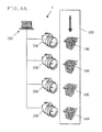
- MFP 100 that the work of an assembly or the like completed proceeds to the process of an adjustment value setup. Then, MFP 100 is put on the predetermined conveyor of a production line. This production line is suitably changed by the classification of MFP 100. Conveyor 600 runs toward light irradiating part 200 of communication terminal apparatus 300, as shown in FIG. 6A .
- an operator exposes manuscript stand 101 of MFP 100 outside, and it becomes a state where image reading part 103 can receive an external light.
- the operator inputs proceed to optical-communications mode into MFP 100 via the key operation of operation part 102.
- display reception part 401 of MFP 100 receives proceeding to the optical-communications mode and notifies that to optical communication part 402.
- Optical-communication receive part 402 that received the notice starts image sensor 108 of image reading part 103.
- optical-communication receive part 402 is changed from normal mode to the optical-communications mode that can receive an external light via the image reading part 103 ( FIG. 5 : S101).
- optical-communication receive part 402 becomes in the state that optical communications are possible.
- Optical-communications receive section 402 receives an external light, and it starts detection of the head signal of the received light signal ( FIG. 5 : S102).
- optical-communication receive part 402 to detect the head signal of optical communications by optical-communication receive part 402, any kind of methods may be used. However, for example, when optical-communication receive part 402 receives an external light, the method of comparing the received light signal and the head signal previously set up by the manufacturer can be mentioned. In this case, only if the light signal matches with the head signal, the head signal is detected.
- optical-communication receive part 402 cannot detect the head signal in the case of reception of light ( FIG. 5 : NO in S102), unless cancel the optical-communications mode, detection of the head signal will be repeated.
- MFP 100 completes a change in the optical-communications mode, for example, via touch panel 201 of operation part 102, the completion screen of changing is shown.
- the operator verifies the screen, then, goes to communication terminal apparatus 300 of data setting system 1, and starts communication terminal apparatus 300.
- control part 403 of communication terminal apparatus 300 shows a predetermined operation screen.
- the operator inputs an optical-communications start instruction into communication terminal apparatus 300 via a mouse, a keyboard, or the like.
- control part 403 of communication terminal apparatus 300 notifies that effect to optical-communication sending part 404.
- Optical-communication sending part 404 that received the notice sends the light signal corresponding to the setup of data by using light irradiating part 200 connected to communication terminal apparatus 300.
- optical-communication sending part 404 converts into a light signal the command that starts the setting process of the adjustment value used as data and the adjustment value of data.
- optical-communication sending part 404 sends the converted light signal via light irradiating part 200.
- adjustment values are destination information (for Japan, for the United States, or the like), a serial number, or the like, for example. Thereby, the light irradiated from light irradiating part 200 will be sent outside as the light signal.
- optical communications is one way from communication terminal apparatus 300 to MFP 100. Therefore, optical-communication sending part 404 repeats and sends a series of light signals required for the setup of the adjustment value. Thereby, optical-communication receive part 402 in MFP 100 enables to receive the light signal certainly.
- optical-communication sending part 404 arranges the head signal and the termination signal to a head and an end in the light signals, respectively. Thereby, optical-communication receive part 402 of MFP 100 that receives the light signal becomes possible to identify the head and the end of the light signal.
- light irradiating part 200 that optical-communication sending part 404 uses any kind of a member in which optical communications are possible may be sufficient.
- a light source for visible light communications can be mentioned.
- optical-communication sending part 404 of communication terminal apparatus 300 sending the light signal
- MFP 100 on conveyor 600 is conveyed and passed a lower part of light irradiating part 200.
- optical-communication receive part 402 of MFP 100 detects the head signal of optical communications ( FIG. 5 : YES in S102) and starts reception of the light signal from the head signal ( FIG. 5 : S103).
- reception of the light signal of optical-communication receive part 402 is continuously performed ( FIG. 5 : S103) until it detects the termination signal of the light signal ( FIG. 5 : NO in S104).
- Detection of the termination signal of optical communications is the similar manner as that of the head signal. That is, optical-communication receive part 402 compares the received light signal and the termination signal previously set up by the manufacturer. If the light signal matches with the termination signal, the termination signal is detected.
- optical-communication receive part 402 detects the termination signal ( FIG. 5 : YES in S104), reception of the light signal will be completed and that effect will be notified to optical-communication execution part 405.
- Optical-communication execution part 405 that received the notice performs a setup of the adjustment value corresponding to the received light signal ( FIG. 5 : S105).
- optical-communication execution part 405 may convert a command, an adjustment value, or the like, that start the setting process of the adjustment value as the received light signal.
- optical-communication execution part 405 executes the converted command and performs setting process of the adjustment value.
- optical-communication execution part 405 completes performing of the setup of the adjustment value, that effect is notified to display reception part 401.
- display reception part 401 shows the completion screen about setting of the setup of the adjustment value having been completed on touch panel 201 ( FIG. 5 : S106).
- one way optical communications from communication terminal apparatus 300 is mentioned. Accordingly, completion of the setup of the adjustment value of MFP 100 cannot be verified from communication terminal apparatus 300. Therefore, by the completion screen of the setting, the operator can be verified the setup of the adjustment value of MFP 100 is completed, visually.
- control part 403 checks that the setup of the adjustment value of MFP 100 has been completed based on the taken image of the completion screen of the setting. Thereby, not only visual inspection by the operator but the automatic check by communication terminal apparatus 300 is attained.
- image reading part 103 of MFP 100 it becomes possible, without using physical connection, to set up the adjustment value by optical communications. Also, since image reading part 103 always exists in MFP 100, by using it effectively with optical communications, it becomes possible to avoid the increase number for new parts.
- MFP 100 when MFP 100 only flows on conveyor 600 of the production line, it becomes possible to carry out a setup of the adjustment value of MFP 100, and there is no connection of a telecommunication cable by the operator.
- optical communications performed with image sensor 108 of image reading part 103 are considered to be a low speed as compared with general optical communications.
- modification of the adjustment value can be easily performed by setting up the adjustment value with the optical communications as mentioned above. Therefore, it becomes possible to apply suitably in case that the production of MFP 100 is as various kinds of small quantity, for example.
- optical-communications mode instructions,
- other components may be used.
- optical-communication receive part 402 may refer to an internal memory about the setup of the adjustment value in MFP 100.
- optical-communication receive part 402 may be configured to shift to optical-communications mode from normal mode, automatically.
- the adjustment value may not be input in the area of a predetermined memory, and it may be a case of a blank. Thereby, it becomes possible to further remove time and effort for the operator.
- a plurality of light irradiating parts 200 are arranged in series along the direction of movement of one conveyor 600. Further, it is configured that communication terminal apparatus 300 sends the same light signal from every light irradiating part 200, and optical communications are performed each of a plurality of MFP 100 on conveyor 600.
- the other configuration is acceptable. For example, the area that can send the light signal on conveyor 600 is determined for a specified light irradiating part 200, a shield (cover) is provided in the area, and only the light signal from the specified light irradiating part 200 can be received in the area. By this configuration, it becomes possible to prevent the optical-communications omission, or the like, for MFP 100 included in the area.
- each light signal sent by light irradiating part 200 can be corresponded to each part of setting process for various data.
- FIG. 6A four sets of light irradiating parts 200 is provided in series along the direction of movement of conveyor 600.
- the first light irradiating part 200 irradiates with the light signal of an initializing step.
- the following light irradiating part 200 irradiates with the light signal of the first adjusting process.
- the third light irradiating part 200 irradiates with the light signal of the second adjusting process.
- the last light irradiating part 200 irradiates with the light signal of a check process. In this way, a series of data setting processes are corresponded as for each light irradiating part 200.
- the data setting is possible when MFP 100 passes within the area where the light of light irradiating part 200 reaches. Therefore, there is an advantage to realize even if it designs the shape of conveyor 600 for a production line freely.
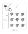
- area 601 in which the optical communications of one light irradiating part 200 are possible (area that the light of light irradiating part 200 reaches) may be determined.
- the light signal of the light irradiating part 200 is sent only to that area.
- an operator conveys a plurality of MFP 100 in the room of the area 601.
- the operator operates each MFP 100, opens manuscript stand 101 (manuscript mat) of MFP 100, and enables it to receive an external light for image reading part 103.
- an operator changes optical-communication receive part 402 of MFP 100 into the states in which optical communications are possible (for example, FW (firmware) update mode in optical-communications mode, or the like.)
- the operator operates communication terminal apparatus 300 and makes a light signal send to optical-communication sending part 404 via light irradiating part 200.
- optical-communication receive part 402 of a plurality of MFP 100 detects the head signal of the light signal, reception of a light signal will be started and reception of the light signal will be continued to detection of the termination signal. Then, when optical-communication receive part 402 completes reception of the light signal, optical-communication execution part 405 will perform the setup of the data corresponding to the light signal. Here, if it is FW update, optical-communication execution part 405 will perform a reboot at the end and will complete FW update.
- MFP 100 includes optical-communication receive part 402 that receives an external light signal by using image reading part 103 and optical-communication execution part 405 that performs a setup of data corresponding to the received light signal.
- communication terminal apparatus 300 provides optical-communication sending part 404 that sends the light signal corresponding to the setup of data by using light irradiating part 200.
- the image forming apparatus is MFP 100, there is no particular limitation, and an image forming apparatus that has image reading part 103 can be used.
- the communication terminal apparatus is personal computer 300, a personal digital assistant apparatus, a tablet type terminal unit, or the like may be used if sending of a light signal is possible by using light irradiating part 200.
- a setup of an adjustment value and FW update are mentioned as a setup of data, there will be no limitation in particular if it is the setting process to input data.
- the program that realizes each part may be stored in a recording medium, and it is configured that the recording medium may be provided.
- the program is read to an image forming apparatus or a communication terminal apparatus, and the image forming apparatus and the communication terminal apparatus realize each part as above.
- the data setting system and data setting method related to the present disclosure are useful as well as a MFP to the data setting system that has a copying machine, a printer, a terminal unit, a tablet type terminal unit, a notebook computer, a personal digital assistant apparatus, or the like.
- a setup that sets adjustment values, such as destination information and a serial number, to the apparatus is performed. It is usually necessary to perform such setup for every apparatus. Therefore, for a plurality of apparatus arranged in series on the ccnveyor of the existing production line, an operator connects a telecommunication cable (for example, USB cable) from the existing dedicated terminal (personal computer for exclusive use).
- a telecommunication cable for example, USB cable
- the adjustment value of each apparatus is set up by transmitting a command and an adjustment value from the dedicated terminal.
- each apparatus and a dedicated terminal need to be physically connected via the telecommunication cable.
- the operator brings the telecommunication cable to the apparatus on the conveyor when performing the setup, the apparatus is connected with it, and the setup is performed by using the dedicated terminal.
- the setup of one apparatus is completed by detaching the telecommunication cable that is connected.
- the method of building wireless LAN such as WiFi, is also considered.
- the data setting system and data setting method that can set up data by using a scanner unit without connecting physically are provided.
- the present disclosure can be provided as a program for performing a computer that can be transmitted individually via electric telecommunication lines, or the like.
- CPU Central Processing Unit
- each part realized by using the program and CPU can also be configured by using hardware for exclusive use.
- the program is possible to circulate in the state recorded on recording medium readable for a computer, such as CD-ROM, or the like.
Landscapes
- Engineering & Computer Science (AREA)
- Multimedia (AREA)
- Signal Processing (AREA)
- General Engineering & Computer Science (AREA)
- Theoretical Computer Science (AREA)
- Computing Systems (AREA)
- Human Computer Interaction (AREA)
- Physics & Mathematics (AREA)
- General Physics & Mathematics (AREA)
- Facsimiles In General (AREA)
- Control Or Security For Electrophotography (AREA)
- Accessory Devices And Overall Control Thereof (AREA)
Applications Claiming Priority (1)
| Application Number | Priority Date | Filing Date | Title |
|---|---|---|---|
| JP2013271842A JP6017413B2 (ja) | 2013-12-27 | 2013-12-27 | データ設定システム及びデータ設定方法 |
Publications (3)
| Publication Number | Publication Date |
|---|---|
| EP2890103A2 true EP2890103A2 (de) | 2015-07-01 |
| EP2890103A3 EP2890103A3 (de) | 2015-11-04 |
| EP2890103B1 EP2890103B1 (de) | 2020-07-29 |
Family
ID=52292696
Family Applications (1)
| Application Number | Title | Priority Date | Filing Date |
|---|---|---|---|
| EP14200300.3A Active EP2890103B1 (de) | 2013-12-27 | 2014-12-24 | Dateneinstellungssystem und Dateneinstellungsverfahren |
Country Status (4)
| Country | Link |
|---|---|
| US (1) | US9262108B2 (de) |
| EP (1) | EP2890103B1 (de) |
| JP (1) | JP6017413B2 (de) |
| CN (1) | CN104754164B (de) |
Families Citing this family (8)
| Publication number | Priority date | Publication date | Assignee | Title |
|---|---|---|---|---|
| JP6387925B2 (ja) * | 2015-09-01 | 2018-09-12 | コニカミノルタ株式会社 | 画像処理システム、画像処理装置及びプログラム |
| JP6108010B1 (ja) * | 2016-06-08 | 2017-04-05 | 富士ゼロックス株式会社 | 携帯情報処理装置、画像出力装置、画像出力システム、情報処理プログラム及び画像処理プログラム |
| US9876929B2 (en) * | 2016-01-05 | 2018-01-23 | Fuji Xerox Co., Ltd. | Image output device, image output system, mobile information processing device, image output method, and non-transitory computer readable medium |
| JP6078177B1 (ja) * | 2016-01-05 | 2017-02-08 | 富士ゼロックス株式会社 | 画像出力装置、画像出力システム及び画像出力プログラム |
| US10051143B2 (en) | 2016-01-05 | 2018-08-14 | Fuji Xerox Co., Ltd. | Mobile information processing apparatus, image output apparatus, image output system, and non-transitory computer readable medium |
| US10097719B2 (en) | 2016-11-17 | 2018-10-09 | Fuji Xerox Co., Ltd. | Printer and mobile information processing apparatus |
| US10133528B2 (en) | 2016-11-28 | 2018-11-20 | Fuji Xerox Co., Ltd. | Information processing apparatus, printer, and non-transitory computer readable medium |
| JP2018112594A (ja) * | 2017-01-10 | 2018-07-19 | 富士ゼロックス株式会社 | 画像形成装置 |
Family Cites Families (9)
| Publication number | Priority date | Publication date | Assignee | Title |
|---|---|---|---|---|
| JPH05169356A (ja) | 1991-12-17 | 1993-07-09 | Hitachi Ltd | 生産ラインにおける調整・検査対象に対する調整・検査方法とその生産ライン並びに調整・検査対象位置決め載置用台板 |
| KR100617679B1 (ko) * | 2004-05-28 | 2006-08-28 | 삼성전자주식회사 | 카메라 장치를 이용하여 가시광선 근거리 통신을 수행하는무선 단말기 |
| JP2006013673A (ja) * | 2004-06-23 | 2006-01-12 | Murata Mach Ltd | 画像読取装置 |
| JP2006270808A (ja) * | 2005-03-25 | 2006-10-05 | Nec Corp | 移動体通信ネットワークシステム、携帯通信端末、認証装置及びこれらの駆動方法、駆動プログラム |
| JPWO2007032394A1 (ja) * | 2005-09-13 | 2009-03-19 | 株式会社ニコン | データ通信装置、電子カメラおよびデータ通信システム |
| JP5110805B2 (ja) * | 2005-11-18 | 2012-12-26 | キヤノン株式会社 | 有線及び無線通信可能な通信端末、通信方法、プログラム |
| KR101508976B1 (ko) * | 2007-12-31 | 2015-04-10 | 삼성전자주식회사 | 가시광 통신을 이용한 네비게이션 시스템 및 방법 |
| US9287976B2 (en) * | 2011-07-26 | 2016-03-15 | Abl Ip Holding Llc | Independent beacon based light position system |
| JP2013251591A (ja) * | 2012-05-30 | 2013-12-12 | Seiko Epson Corp | 複写機 |
-
2013
- 2013-12-27 JP JP2013271842A patent/JP6017413B2/ja not_active Expired - Fee Related
-
2014
- 2014-12-24 EP EP14200300.3A patent/EP2890103B1/de active Active
- 2014-12-25 CN CN201410823095.7A patent/CN104754164B/zh not_active Expired - Fee Related
- 2014-12-27 US US14/583,603 patent/US9262108B2/en not_active Expired - Fee Related
Also Published As
| Publication number | Publication date |
|---|---|
| JP6017413B2 (ja) | 2016-11-02 |
| EP2890103B1 (de) | 2020-07-29 |
| EP2890103A3 (de) | 2015-11-04 |
| CN104754164B (zh) | 2019-03-15 |
| US9262108B2 (en) | 2016-02-16 |
| CN104754164A (zh) | 2015-07-01 |
| JP2015126504A (ja) | 2015-07-06 |
| US20150186088A1 (en) | 2015-07-02 |
Similar Documents
| Publication | Publication Date | Title |
|---|---|---|
| US9262108B2 (en) | Data setting system and data setting method that use optical-communication | |
| US9319559B2 (en) | Image processing system, image processing apparatus, and information processing apparatus | |
| US8780364B2 (en) | Electronic apparatus and information displaying method | |
| CN102291508A (zh) | 图像处理装置及管理装置 | |
| JP2013059986A (ja) | 操作パネル、操作パネルの制御方法、および操作パネルの制御プログラム | |
| JP6610672B2 (ja) | 画像形成装置、画像形成方法 | |
| CN108696664B (zh) | 图像处理设备 | |
| US9542142B2 (en) | Image forming apparatus and discharge destination display method | |
| JP2019116007A (ja) | 故障診断システムおよび故障診断方法 | |
| US10122890B2 (en) | Image forming apparatus and tangible computer-readable recording medium | |
| JP6264310B2 (ja) | 画像形成用シート供給部選択方法、画像形成装置、情報処理装置 | |
| JP6380201B2 (ja) | 画像形成装置 | |
| US9405259B2 (en) | Image forming apparatus having function of printing on index sheet, image forming system, and non-transitory computer-readable recording medium | |
| US8681362B2 (en) | Position detecting apparatus, position detecting method, and image forming apparatus | |
| US20140325010A1 (en) | Electronic apparatus and log information transfer method | |
| JP2015133559A (ja) | 画像形成装置、情報端末装置、画像形成システム、画像形成装置管理制御方法、画像形成装置制御プログラムおよび情報端末装置制御プログラム | |
| JP7115268B2 (ja) | 画像形成装置及びプログラム | |
| JP2015093395A (ja) | 画像形成装置、画像形成システム、画像形成方法 | |
| JP5840173B2 (ja) | 情報処理装置、入出力制御部の再起動方法 | |
| JP2013094980A (ja) | 電子機器および画像形成装置 | |
| CN110035192B (zh) | 图像形成装置 | |
| JP2016063514A (ja) | 電子機器、及び画像形成装置 | |
| JP5663442B2 (ja) | 画像形成装置および画像形成システム | |
| CN113766075A (zh) | 印刷系统、信息处理装置、存储介质以及控制方法 | |
| CN111077747A (zh) | 图像形成装置及图像形成装置的控制方法 |
Legal Events
| Date | Code | Title | Description |
|---|---|---|---|
| PUAI | Public reference made under article 153(3) epc to a published international application that has entered the european phase |
Free format text: ORIGINAL CODE: 0009012 |
|
| 17P | Request for examination filed |
Effective date: 20141224 |
|
| AK | Designated contracting states |
Kind code of ref document: A2 Designated state(s): AL AT BE BG CH CY CZ DE DK EE ES FI FR GB GR HR HU IE IS IT LI LT LU LV MC MK MT NL NO PL PT RO RS SE SI SK SM TR |
|
| AX | Request for extension of the european patent |
Extension state: BA ME |
|
| PUAL | Search report despatched |
Free format text: ORIGINAL CODE: 0009013 |
|
| AK | Designated contracting states |
Kind code of ref document: A3 Designated state(s): AL AT BE BG CH CY CZ DE DK EE ES FI FR GB GR HR HU IE IS IT LI LT LU LV MC MK MT NL NO PL PT RO RS SE SI SK SM TR |
|
| AX | Request for extension of the european patent |
Extension state: BA ME |
|
| RIC1 | Information provided on ipc code assigned before grant |
Ipc: H04N 1/00 20060101AFI20150930BHEP |
|
| RBV | Designated contracting states (corrected) |
Designated state(s): AL AT BE BG CH CY CZ DE DK EE ES FI FR GB GR HR HU IE IS IT LI LT LU LV MC MK MT NL NO PL PT RO RS SE SI SK SM TR |
|
| STAA | Information on the status of an ep patent application or granted ep patent |
Free format text: STATUS: EXAMINATION IS IN PROGRESS |
|
| 17Q | First examination report despatched |
Effective date: 20190410 |
|
| GRAP | Despatch of communication of intention to grant a patent |
Free format text: ORIGINAL CODE: EPIDOSNIGR1 |
|
| STAA | Information on the status of an ep patent application or granted ep patent |
Free format text: STATUS: GRANT OF PATENT IS INTENDED |
|
| INTG | Intention to grant announced |
Effective date: 20200212 |
|
| GRAS | Grant fee paid |
Free format text: ORIGINAL CODE: EPIDOSNIGR3 |
|
| GRAA | (expected) grant |
Free format text: ORIGINAL CODE: 0009210 |
|
| STAA | Information on the status of an ep patent application or granted ep patent |
Free format text: STATUS: THE PATENT HAS BEEN GRANTED |
|
| AK | Designated contracting states |
Kind code of ref document: B1 Designated state(s): AL AT BE BG CH CY CZ DE DK EE ES FI FR GB GR HR HU IE IS IT LI LT LU LV MC MK MT NL NO PL PT RO RS SE SI SK SM TR |
|
| REG | Reference to a national code |
Ref country code: CH Ref legal event code: EP |
|
| REG | Reference to a national code |
Ref country code: AT Ref legal event code: REF Ref document number: 1297191 Country of ref document: AT Kind code of ref document: T Effective date: 20200815 |
|
| REG | Reference to a national code |
Ref country code: IE Ref legal event code: FG4D |
|
| REG | Reference to a national code |
Ref country code: DE Ref legal event code: R096 Ref document number: 602014068231 Country of ref document: DE |
|
| REG | Reference to a national code |
Ref country code: LT Ref legal event code: MG4D |
|
| REG | Reference to a national code |
Ref country code: NL Ref legal event code: MP Effective date: 20200729 |
|
| REG | Reference to a national code |
Ref country code: AT Ref legal event code: MK05 Ref document number: 1297191 Country of ref document: AT Kind code of ref document: T Effective date: 20200729 |
|
| PG25 | Lapsed in a contracting state [announced via postgrant information from national office to epo] |
Ref country code: ES Free format text: LAPSE BECAUSE OF FAILURE TO SUBMIT A TRANSLATION OF THE DESCRIPTION OR TO PAY THE FEE WITHIN THE PRESCRIBED TIME-LIMIT Effective date: 20200729 Ref country code: GR Free format text: LAPSE BECAUSE OF FAILURE TO SUBMIT A TRANSLATION OF THE DESCRIPTION OR TO PAY THE FEE WITHIN THE PRESCRIBED TIME-LIMIT Effective date: 20201030 Ref country code: HR Free format text: LAPSE BECAUSE OF FAILURE TO SUBMIT A TRANSLATION OF THE DESCRIPTION OR TO PAY THE FEE WITHIN THE PRESCRIBED TIME-LIMIT Effective date: 20200729 Ref country code: LT Free format text: LAPSE BECAUSE OF FAILURE TO SUBMIT A TRANSLATION OF THE DESCRIPTION OR TO PAY THE FEE WITHIN THE PRESCRIBED TIME-LIMIT Effective date: 20200729 Ref country code: PT Free format text: LAPSE BECAUSE OF FAILURE TO SUBMIT A TRANSLATION OF THE DESCRIPTION OR TO PAY THE FEE WITHIN THE PRESCRIBED TIME-LIMIT Effective date: 20201130 Ref country code: FI Free format text: LAPSE BECAUSE OF FAILURE TO SUBMIT A TRANSLATION OF THE DESCRIPTION OR TO PAY THE FEE WITHIN THE PRESCRIBED TIME-LIMIT Effective date: 20200729 Ref country code: SE Free format text: LAPSE BECAUSE OF FAILURE TO SUBMIT A TRANSLATION OF THE DESCRIPTION OR TO PAY THE FEE WITHIN THE PRESCRIBED TIME-LIMIT Effective date: 20200729 Ref country code: AT Free format text: LAPSE BECAUSE OF FAILURE TO SUBMIT A TRANSLATION OF THE DESCRIPTION OR TO PAY THE FEE WITHIN THE PRESCRIBED TIME-LIMIT Effective date: 20200729 Ref country code: BG Free format text: LAPSE BECAUSE OF FAILURE TO SUBMIT A TRANSLATION OF THE DESCRIPTION OR TO PAY THE FEE WITHIN THE PRESCRIBED TIME-LIMIT Effective date: 20201029 Ref country code: NO Free format text: LAPSE BECAUSE OF FAILURE TO SUBMIT A TRANSLATION OF THE DESCRIPTION OR TO PAY THE FEE WITHIN THE PRESCRIBED TIME-LIMIT Effective date: 20201029 |
|
| PG25 | Lapsed in a contracting state [announced via postgrant information from national office to epo] |
Ref country code: IS Free format text: LAPSE BECAUSE OF FAILURE TO SUBMIT A TRANSLATION OF THE DESCRIPTION OR TO PAY THE FEE WITHIN THE PRESCRIBED TIME-LIMIT Effective date: 20201129 Ref country code: RS Free format text: LAPSE BECAUSE OF FAILURE TO SUBMIT A TRANSLATION OF THE DESCRIPTION OR TO PAY THE FEE WITHIN THE PRESCRIBED TIME-LIMIT Effective date: 20200729 Ref country code: PL Free format text: LAPSE BECAUSE OF FAILURE TO SUBMIT A TRANSLATION OF THE DESCRIPTION OR TO PAY THE FEE WITHIN THE PRESCRIBED TIME-LIMIT Effective date: 20200729 Ref country code: LV Free format text: LAPSE BECAUSE OF FAILURE TO SUBMIT A TRANSLATION OF THE DESCRIPTION OR TO PAY THE FEE WITHIN THE PRESCRIBED TIME-LIMIT Effective date: 20200729 |
|
| PG25 | Lapsed in a contracting state [announced via postgrant information from national office to epo] |
Ref country code: NL Free format text: LAPSE BECAUSE OF FAILURE TO SUBMIT A TRANSLATION OF THE DESCRIPTION OR TO PAY THE FEE WITHIN THE PRESCRIBED TIME-LIMIT Effective date: 20200729 |
|
| PG25 | Lapsed in a contracting state [announced via postgrant information from national office to epo] |
Ref country code: SM Free format text: LAPSE BECAUSE OF FAILURE TO SUBMIT A TRANSLATION OF THE DESCRIPTION OR TO PAY THE FEE WITHIN THE PRESCRIBED TIME-LIMIT Effective date: 20200729 Ref country code: RO Free format text: LAPSE BECAUSE OF FAILURE TO SUBMIT A TRANSLATION OF THE DESCRIPTION OR TO PAY THE FEE WITHIN THE PRESCRIBED TIME-LIMIT Effective date: 20200729 Ref country code: DK Free format text: LAPSE BECAUSE OF FAILURE TO SUBMIT A TRANSLATION OF THE DESCRIPTION OR TO PAY THE FEE WITHIN THE PRESCRIBED TIME-LIMIT Effective date: 20200729 Ref country code: CZ Free format text: LAPSE BECAUSE OF FAILURE TO SUBMIT A TRANSLATION OF THE DESCRIPTION OR TO PAY THE FEE WITHIN THE PRESCRIBED TIME-LIMIT Effective date: 20200729 Ref country code: EE Free format text: LAPSE BECAUSE OF FAILURE TO SUBMIT A TRANSLATION OF THE DESCRIPTION OR TO PAY THE FEE WITHIN THE PRESCRIBED TIME-LIMIT Effective date: 20200729 Ref country code: IT Free format text: LAPSE BECAUSE OF FAILURE TO SUBMIT A TRANSLATION OF THE DESCRIPTION OR TO PAY THE FEE WITHIN THE PRESCRIBED TIME-LIMIT Effective date: 20200729 |
|
| REG | Reference to a national code |
Ref country code: DE Ref legal event code: R097 Ref document number: 602014068231 Country of ref document: DE |
|
| PG25 | Lapsed in a contracting state [announced via postgrant information from national office to epo] |
Ref country code: AL Free format text: LAPSE BECAUSE OF FAILURE TO SUBMIT A TRANSLATION OF THE DESCRIPTION OR TO PAY THE FEE WITHIN THE PRESCRIBED TIME-LIMIT Effective date: 20200729 |
|
| PLBE | No opposition filed within time limit |
Free format text: ORIGINAL CODE: 0009261 |
|
| STAA | Information on the status of an ep patent application or granted ep patent |
Free format text: STATUS: NO OPPOSITION FILED WITHIN TIME LIMIT |
|
| PG25 | Lapsed in a contracting state [announced via postgrant information from national office to epo] |
Ref country code: SK Free format text: LAPSE BECAUSE OF FAILURE TO SUBMIT A TRANSLATION OF THE DESCRIPTION OR TO PAY THE FEE WITHIN THE PRESCRIBED TIME-LIMIT Effective date: 20200729 |
|
| 26N | No opposition filed |
Effective date: 20210430 |
|
| REG | Reference to a national code |
Ref country code: CH Ref legal event code: PL |
|
| GBPC | Gb: european patent ceased through non-payment of renewal fee |
Effective date: 20201224 |
|
| PG25 | Lapsed in a contracting state [announced via postgrant information from national office to epo] |
Ref country code: SI Free format text: LAPSE BECAUSE OF FAILURE TO SUBMIT A TRANSLATION OF THE DESCRIPTION OR TO PAY THE FEE WITHIN THE PRESCRIBED TIME-LIMIT Effective date: 20200729 Ref country code: MC Free format text: LAPSE BECAUSE OF FAILURE TO SUBMIT A TRANSLATION OF THE DESCRIPTION OR TO PAY THE FEE WITHIN THE PRESCRIBED TIME-LIMIT Effective date: 20200729 |
|
| REG | Reference to a national code |
Ref country code: BE Ref legal event code: MM Effective date: 20201231 |
|
| PG25 | Lapsed in a contracting state [announced via postgrant information from national office to epo] |
Ref country code: LU Free format text: LAPSE BECAUSE OF NON-PAYMENT OF DUE FEES Effective date: 20201224 Ref country code: FR Free format text: LAPSE BECAUSE OF NON-PAYMENT OF DUE FEES Effective date: 20201231 Ref country code: IE Free format text: LAPSE BECAUSE OF NON-PAYMENT OF DUE FEES Effective date: 20201224 |
|
| PG25 | Lapsed in a contracting state [announced via postgrant information from national office to epo] |
Ref country code: LI Free format text: LAPSE BECAUSE OF NON-PAYMENT OF DUE FEES Effective date: 20201231 Ref country code: CH Free format text: LAPSE BECAUSE OF NON-PAYMENT OF DUE FEES Effective date: 20201231 Ref country code: GB Free format text: LAPSE BECAUSE OF NON-PAYMENT OF DUE FEES Effective date: 20201224 |
|
| PG25 | Lapsed in a contracting state [announced via postgrant information from national office to epo] |
Ref country code: IS Free format text: LAPSE BECAUSE OF FAILURE TO SUBMIT A TRANSLATION OF THE DESCRIPTION OR TO PAY THE FEE WITHIN THE PRESCRIBED TIME-LIMIT Effective date: 20201129 Ref country code: TR Free format text: LAPSE BECAUSE OF FAILURE TO SUBMIT A TRANSLATION OF THE DESCRIPTION OR TO PAY THE FEE WITHIN THE PRESCRIBED TIME-LIMIT Effective date: 20200729 Ref country code: MT Free format text: LAPSE BECAUSE OF FAILURE TO SUBMIT A TRANSLATION OF THE DESCRIPTION OR TO PAY THE FEE WITHIN THE PRESCRIBED TIME-LIMIT Effective date: 20200729 Ref country code: CY Free format text: LAPSE BECAUSE OF FAILURE TO SUBMIT A TRANSLATION OF THE DESCRIPTION OR TO PAY THE FEE WITHIN THE PRESCRIBED TIME-LIMIT Effective date: 20200729 |
|
| PG25 | Lapsed in a contracting state [announced via postgrant information from national office to epo] |
Ref country code: MK Free format text: LAPSE BECAUSE OF FAILURE TO SUBMIT A TRANSLATION OF THE DESCRIPTION OR TO PAY THE FEE WITHIN THE PRESCRIBED TIME-LIMIT Effective date: 20200729 |
|
| PG25 | Lapsed in a contracting state [announced via postgrant information from national office to epo] |
Ref country code: BE Free format text: LAPSE BECAUSE OF NON-PAYMENT OF DUE FEES Effective date: 20201231 |
|
| PGFP | Annual fee paid to national office [announced via postgrant information from national office to epo] |
Ref country code: DE Payment date: 20221122 Year of fee payment: 9 |
|
| P01 | Opt-out of the competence of the unified patent court (upc) registered |
Effective date: 20230420 |
|
| REG | Reference to a national code |
Ref country code: DE Ref legal event code: R119 Ref document number: 602014068231 Country of ref document: DE |
|
| PG25 | Lapsed in a contracting state [announced via postgrant information from national office to epo] |
Ref country code: DE Free format text: LAPSE BECAUSE OF NON-PAYMENT OF DUE FEES Effective date: 20240702 |
|
| PG25 | Lapsed in a contracting state [announced via postgrant information from national office to epo] |
Ref country code: DE Free format text: LAPSE BECAUSE OF NON-PAYMENT OF DUE FEES Effective date: 20240702 |