EP2888157B2 - Elektronisch gesteuertes federungssystem, verfahren zur steuerung eines federungssystems und computerprogramm - Google Patents
Elektronisch gesteuertes federungssystem, verfahren zur steuerung eines federungssystems und computerprogramm Download PDFInfo
- Publication number
- EP2888157B2 EP2888157B2 EP13750585.5A EP13750585A EP2888157B2 EP 2888157 B2 EP2888157 B2 EP 2888157B2 EP 13750585 A EP13750585 A EP 13750585A EP 2888157 B2 EP2888157 B2 EP 2888157B2
- Authority
- EP
- European Patent Office
- Prior art keywords
- seat post
- electronic module
- bicycle
- operating state
- post according
- Prior art date
- Legal status (The legal status is an assumption and is not a legal conclusion. Google has not performed a legal analysis and makes no representation as to the accuracy of the status listed.)
- Active
Links
Images




Classifications
-
- B—PERFORMING OPERATIONS; TRANSPORTING
- B62—LAND VEHICLES FOR TRAVELLING OTHERWISE THAN ON RAILS
- B62J—CYCLE SADDLES OR SEATS; AUXILIARY DEVICES OR ACCESSORIES SPECIALLY ADAPTED TO CYCLES AND NOT OTHERWISE PROVIDED FOR, e.g. ARTICLE CARRIERS OR CYCLE PROTECTORS
- B62J50/00—Arrangements specially adapted for use on cycles not provided for in main groups B62J1/00 - B62J45/00
- B62J50/20—Information-providing devices
- B62J50/21—Information-providing devices intended to provide information to rider or passenger
- B62J50/22—Information-providing devices intended to provide information to rider or passenger electronic, e.g. displays
-
- B—PERFORMING OPERATIONS; TRANSPORTING
- B62—LAND VEHICLES FOR TRAVELLING OTHERWISE THAN ON RAILS
- B62J—CYCLE SADDLES OR SEATS; AUXILIARY DEVICES OR ACCESSORIES SPECIALLY ADAPTED TO CYCLES AND NOT OTHERWISE PROVIDED FOR, e.g. ARTICLE CARRIERS OR CYCLE PROTECTORS
- B62J1/00—Saddles or other seats for cycles; Arrangement thereof; Component parts
- B62J1/02—Saddles resiliently mounted on the frame; Equipment therefor, e.g. springs
- B62J1/06—Saddles capable of parallel motion up and down
-
- B—PERFORMING OPERATIONS; TRANSPORTING
- B62—LAND VEHICLES FOR TRAVELLING OTHERWISE THAN ON RAILS
- B62J—CYCLE SADDLES OR SEATS; AUXILIARY DEVICES OR ACCESSORIES SPECIALLY ADAPTED TO CYCLES AND NOT OTHERWISE PROVIDED FOR, e.g. ARTICLE CARRIERS OR CYCLE PROTECTORS
- B62J45/00—Electrical equipment arrangements specially adapted for use as accessories on cycles, not otherwise provided for
- B62J45/20—Cycle computers as cycle accessories
-
- B—PERFORMING OPERATIONS; TRANSPORTING
- B62—LAND VEHICLES FOR TRAVELLING OTHERWISE THAN ON RAILS
- B62J—CYCLE SADDLES OR SEATS; AUXILIARY DEVICES OR ACCESSORIES SPECIALLY ADAPTED TO CYCLES AND NOT OTHERWISE PROVIDED FOR, e.g. ARTICLE CARRIERS OR CYCLE PROTECTORS
- B62J45/00—Electrical equipment arrangements specially adapted for use as accessories on cycles, not otherwise provided for
- B62J45/40—Sensor arrangements; Mounting thereof
- B62J45/41—Sensor arrangements; Mounting thereof characterised by the type of sensor
- B62J45/412—Speed sensors
-
- B—PERFORMING OPERATIONS; TRANSPORTING
- B62—LAND VEHICLES FOR TRAVELLING OTHERWISE THAN ON RAILS
- B62J—CYCLE SADDLES OR SEATS; AUXILIARY DEVICES OR ACCESSORIES SPECIALLY ADAPTED TO CYCLES AND NOT OTHERWISE PROVIDED FOR, e.g. ARTICLE CARRIERS OR CYCLE PROTECTORS
- B62J45/00—Electrical equipment arrangements specially adapted for use as accessories on cycles, not otherwise provided for
- B62J45/40—Sensor arrangements; Mounting thereof
- B62J45/41—Sensor arrangements; Mounting thereof characterised by the type of sensor
- B62J45/414—Acceleration sensors
-
- B—PERFORMING OPERATIONS; TRANSPORTING
- B62—LAND VEHICLES FOR TRAVELLING OTHERWISE THAN ON RAILS
- B62J—CYCLE SADDLES OR SEATS; AUXILIARY DEVICES OR ACCESSORIES SPECIALLY ADAPTED TO CYCLES AND NOT OTHERWISE PROVIDED FOR, e.g. ARTICLE CARRIERS OR CYCLE PROTECTORS
- B62J45/00—Electrical equipment arrangements specially adapted for use as accessories on cycles, not otherwise provided for
- B62J45/40—Sensor arrangements; Mounting thereof
- B62J45/41—Sensor arrangements; Mounting thereof characterised by the type of sensor
- B62J45/415—Inclination sensors
-
- B—PERFORMING OPERATIONS; TRANSPORTING
- B62—LAND VEHICLES FOR TRAVELLING OTHERWISE THAN ON RAILS
- B62K—CYCLES; CYCLE FRAMES; CYCLE STEERING DEVICES; RIDER-OPERATED TERMINAL CONTROLS SPECIALLY ADAPTED FOR CYCLES; CYCLE AXLE SUSPENSIONS; CYCLE SIDECARS, FORECARS, OR THE LIKE
- B62K25/00—Axle suspensions
- B62K25/04—Axle suspensions for mounting axles resiliently on cycle frame or fork
- B62K25/06—Axle suspensions for mounting axles resiliently on cycle frame or fork with telescopic fork, e.g. including auxiliary rocking arms
- B62K25/08—Axle suspensions for mounting axles resiliently on cycle frame or fork with telescopic fork, e.g. including auxiliary rocking arms for front wheel
-
- B—PERFORMING OPERATIONS; TRANSPORTING
- B62—LAND VEHICLES FOR TRAVELLING OTHERWISE THAN ON RAILS
- B62K—CYCLES; CYCLE FRAMES; CYCLE STEERING DEVICES; RIDER-OPERATED TERMINAL CONTROLS SPECIALLY ADAPTED FOR CYCLES; CYCLE AXLE SUSPENSIONS; CYCLE SIDECARS, FORECARS, OR THE LIKE
- B62K25/00—Axle suspensions
- B62K25/04—Axle suspensions for mounting axles resiliently on cycle frame or fork
- B62K25/06—Axle suspensions for mounting axles resiliently on cycle frame or fork with telescopic fork, e.g. including auxiliary rocking arms
- B62K25/10—Axle suspensions for mounting axles resiliently on cycle frame or fork with telescopic fork, e.g. including auxiliary rocking arms for rear wheel
-
- B—PERFORMING OPERATIONS; TRANSPORTING
- B62—LAND VEHICLES FOR TRAVELLING OTHERWISE THAN ON RAILS
- B62K—CYCLES; CYCLE FRAMES; CYCLE STEERING DEVICES; RIDER-OPERATED TERMINAL CONTROLS SPECIALLY ADAPTED FOR CYCLES; CYCLE AXLE SUSPENSIONS; CYCLE SIDECARS, FORECARS, OR THE LIKE
- B62K25/00—Axle suspensions
- B62K25/04—Axle suspensions for mounting axles resiliently on cycle frame or fork
- B62K25/12—Axle suspensions for mounting axles resiliently on cycle frame or fork with rocking arm pivoted on each fork leg
- B62K25/14—Axle suspensions for mounting axles resiliently on cycle frame or fork with rocking arm pivoted on each fork leg with single arm on each fork leg
- B62K25/20—Axle suspensions for mounting axles resiliently on cycle frame or fork with rocking arm pivoted on each fork leg with single arm on each fork leg for rear wheel
-
- B—PERFORMING OPERATIONS; TRANSPORTING
- B62—LAND VEHICLES FOR TRAVELLING OTHERWISE THAN ON RAILS
- B62J—CYCLE SADDLES OR SEATS; AUXILIARY DEVICES OR ACCESSORIES SPECIALLY ADAPTED TO CYCLES AND NOT OTHERWISE PROVIDED FOR, e.g. ARTICLE CARRIERS OR CYCLE PROTECTORS
- B62J45/00—Electrical equipment arrangements specially adapted for use as accessories on cycles, not otherwise provided for
-
- B—PERFORMING OPERATIONS; TRANSPORTING
- B62—LAND VEHICLES FOR TRAVELLING OTHERWISE THAN ON RAILS
- B62J—CYCLE SADDLES OR SEATS; AUXILIARY DEVICES OR ACCESSORIES SPECIALLY ADAPTED TO CYCLES AND NOT OTHERWISE PROVIDED FOR, e.g. ARTICLE CARRIERS OR CYCLE PROTECTORS
- B62J45/00—Electrical equipment arrangements specially adapted for use as accessories on cycles, not otherwise provided for
- B62J45/40—Sensor arrangements; Mounting thereof
- B62J45/41—Sensor arrangements; Mounting thereof characterised by the type of sensor
- B62J45/411—Torque sensors
-
- B—PERFORMING OPERATIONS; TRANSPORTING
- B62—LAND VEHICLES FOR TRAVELLING OTHERWISE THAN ON RAILS
- B62J—CYCLE SADDLES OR SEATS; AUXILIARY DEVICES OR ACCESSORIES SPECIALLY ADAPTED TO CYCLES AND NOT OTHERWISE PROVIDED FOR, e.g. ARTICLE CARRIERS OR CYCLE PROTECTORS
- B62J45/00—Electrical equipment arrangements specially adapted for use as accessories on cycles, not otherwise provided for
- B62J45/40—Sensor arrangements; Mounting thereof
- B62J45/41—Sensor arrangements; Mounting thereof characterised by the type of sensor
- B62J45/415—Inclination sensors
- B62J45/4152—Inclination sensors for sensing longitudinal inclination of the cycle
-
- B—PERFORMING OPERATIONS; TRANSPORTING
- B62—LAND VEHICLES FOR TRAVELLING OTHERWISE THAN ON RAILS
- B62K—CYCLES; CYCLE FRAMES; CYCLE STEERING DEVICES; RIDER-OPERATED TERMINAL CONTROLS SPECIALLY ADAPTED FOR CYCLES; CYCLE AXLE SUSPENSIONS; CYCLE SIDECARS, FORECARS, OR THE LIKE
- B62K25/00—Axle suspensions
- B62K25/04—Axle suspensions for mounting axles resiliently on cycle frame or fork
- B62K2025/044—Suspensions with automatic adjustment
-
- B—PERFORMING OPERATIONS; TRANSPORTING
- B62—LAND VEHICLES FOR TRAVELLING OTHERWISE THAN ON RAILS
- B62K—CYCLES; CYCLE FRAMES; CYCLE STEERING DEVICES; RIDER-OPERATED TERMINAL CONTROLS SPECIALLY ADAPTED FOR CYCLES; CYCLE AXLE SUSPENSIONS; CYCLE SIDECARS, FORECARS, OR THE LIKE
- B62K25/00—Axle suspensions
- B62K25/04—Axle suspensions for mounting axles resiliently on cycle frame or fork
- B62K2025/045—Suspensions with ride-height adjustment
Definitions
- the invention relates to an electronically controlled seat post for a bicycle, comprising at least one spring element which is arranged between a first part of the bicycle and a second part of the bicycle, which are movably connected to one another, at least one parameter of the spring element being changeable, and at least one Actuator, which acts on the spring element in order to change the at least one parameter, and an electronics module with which a control signal for the at least one actuator can be generated.
- This known device has the disadvantage that the cable connections can corrode or tear off when the bicycle is used off-road, so that the operational safety of the device is only low. Furthermore, the damping can be adjusted with this known device, but not the spring force, so that an adaptation to different driving conditions is only possible in a rudimentary manner.
- the invention has for its object to provide an electric seat post for a bicycle, which has improved operational safety and / or offers different adjustment options, so that an automated adaptation to different operating conditions is possible.
- a suspension system can either only be arranged on the front wheel of a bicycle.
- the suspension system can be arranged both on the front and on the rear wheel.
- the suspension system can also be arranged only on the rear wheel.
- the suspension system can be arranged in a seat post and / or in a steerer tube. The task of the suspension system is on the one hand to increase the riding comfort for the user of the bicycle.
- the suspension system can enable the wheels to adhere better to the ground, so that the traction can be improved and / or higher steering or braking forces can be transmitted. This can have a positive effect on the driving safety or the off-road ability of the bicycle.
- the bicycle can be a muscle-powered, two-wheeled vehicle, such as a mountain bike, a trekking bike, or a road racing bike.
- the bicycle can have three wheels, for example two front and one rear wheel or one front and two rear wheels.
- the bicycle can have an electric motor that either drives the bicycle at least temporarily as an alternative to the muscle-powered pedal drive or that supports the rider when pedaling. As a result, the bicycle can achieve a higher speed and / or a greater range and / or handle steeper climbs with the same amount of energy used by the rider.
- the bicycle has at least one spring element which is arranged between a first part of the bicycle and a second part of the bicycle, which are movably connected to one another.
- the first, immovable part of the bicycle can be the frame of the bicycle or the standpipes of a fork or the part of a seat post that can be connected to the frame.
- the second, movable part of the bicycle can be formed by the dip tubes of a fork or by a movably mounted rear kinematics of a rear wheel suspension system or the part of a seat post that can be connected to the saddle. Both the weight of the bicycle, the weight of the user and dynamic impacts on the wheels lead to a relative movement between the first part and the second part of the bicycle.
- the spring element counteracts this movement.
- the spring element can include a leaf spring or a coil spring, for example made of steel.
- the spring element can comprise an air spring, ie a piston-cylinder pairing, which is a closed one Includes air volume which is compressed when external forces act.
- the spring element can have a device for generating a damping force, for example an oil volume, which flows through openings in a piston.
- a mechanical intervention in components of the spring element can make it possible to change at least one parameter of the spring element.
- the driving behavior of the bicycle equipped with the spring element can be changed, for example the energy dissipation in the suspension can be reduced or the response behavior can be adapted to different surfaces.
- the parameter of the spring element that can be influenced can be selected from the spring force of the compression stage and / or the damping force and / or the spring travel and / or the lock-out, i.e. a fixing device with which the suspension can be completely blocked.
- the spring element can be equipped with an actuating lever and / or an adjusting wheel, which carries out the mechanical interventions on the spring element in a manner known per se in order to carry out the desired changes.
- the mechanical interventions can include, for example, opening or closing a valve or changing the pretension of a spring or changing the clear width of at least one opening or applying an electric field or applying a magnetic field.
- the actuator is actuated with a control signal, which can be a pulse-width modulated electrical signal, for example.
- the drive signal can be an analog current or voltage signal. This can either determine the switch-on and switch-off time of an actuator or its absolute position.
- the control signal is generated by an electronic module.
- the electronics module generates the control signal as a function of at least one input variable that can be generated with at least one control element.
- the control element can either generate the input variable as a function of the driver's request or automatically from measured values which record the current operating state of the bicycle.
- the radio signal can be coded digitally or analog.
- the radio signal can be selected in the frequency band around 433 MHz. In other embodiments, the radio signal can be selected in the frequency band around 2.4 GHz.
- the radio signal can be encrypted so that interference between different bicycles riding side by side is avoided. Furthermore, the electronically controlled undercarriage cannot be manipulated from the outside if the radio signal is encrypted.
- the encryption can be carried out using cryptography methods known per se, for example AES, WPA, WEP or other methods.
- the radio signal can implement an interface known per se, e.g. WLAN or Bluetooth or Near Field Communication (NFC).
- control element can be an operating element and / or a position sensor and / or a position sensor and / or an acceleration sensor contain.
- the user of the bicycle can intervene manually via the control element and, for example, block the suspension or adapt the damping force and / or the spring travel to a desired damping behavior.
- control element can contain a position sensor which, for example, detects a side inclination of the bicycle when cornering and / or detects upward and downward gradients, so that a softer spring characteristic can be selected on descents and a harder spring characteristic can be selected in climbs with large pedal forces. to avoid or reduce unintentional rocking of the undercarriage.
- an optional torque sensor can be used, which detects the pedal force applied by the driver.
- the control element can alternatively or additionally contain a position sensor with which the position of the bicycle on the earth's surface can be detected.
- the position sensor may be or include a radio navigation system, for example GPS, Glonass, Compass or Galileo.
- the position sensor can also receive and process additional terrestrial radio signals. Additional terrestrial radio signals can be selected from differential GPS or a mobile radio signal such as GSM, LTE or UMTS.
- the control element may include a cellular phone or consist of a cellular phone.
- the mobile phone can be connected to the electronic module using a radio connection known per se, such as Bluetooth.
- the mobile telephone can be connected to the electronic module with a cable connection, for example via a USB interface.
- the system can be regulated or controlled by means of user interventions via the user interface of the mobile telephone and / or the electronic module can provide current configuration data output on the display of the mobile phone.
- software can be executed on the mobile phone which translates the user input into a control signal.
- the mobile phone can retrieve software updates or configuration data or topographical information from an online memory via a GSM interface, via a GPRS interface, via an LTE interface or a comparable interface and make them available to the electronic module or make a backup copy of the memory content of the electronic module store on the online storage.
- the electronics module may include a cellular phone or consist of a cellular phone.
- the mobile phone can be connected to the actuators and / or at least one control element using a radio connection known per se, such as Bluetooth.
- the mobile phone can also be used as an operating element.
- Weight can be saved as a result, since no separate electronics module and / or control element has to be installed on the bicycle.
- the power supply of the electronic module and a GPS system for location and a memory for topography data can also be saved if the mobile phone is equipped with these components.
- the battery of the mobile phone is anyway regularly charged by the user, so that there is no need to charge the electronic unit of the bicycle separately.
- an additional control element can be attached to the bicycle handlebar, which is connected to the mobile phone, for example, via a radio interface or a wired interface.
- This embodiment has the advantage that the mobile phone can be carried in a shock-proof and dust-protected manner, for example in a backpack, and yet the user has direct access to the suspension system remains and the user can be informed about the state of the system.
- the electronics module may include a map memory for holding topographic information.
- the topographical information can represent a course of the road or a road surface in order to automatically ensure that the parameters of the spring elements are always optimally adjusted from the position of the bicycle and the chosen route, without the driver having to intervene manually. For example, a harder spring characteristic can be selected in front of a curve, or a harder spring characteristic can be selected on paved roads than on a gravel road.
- the topographical information can also contain height data, so that the characteristic variable of the spring elements can be selected accordingly depending on the rise or fall.
- the suspension system can contain a speed sensor, which allows the parameter of at least one spring element to be adjusted as a function of the driving speed.
- the speed sensor can be integrated in the position sensor, which simultaneously outputs location and speed data.
- the control element contains an acceleration sensor, so that in the case of high acceleration, which applies a corresponding force to the drive wheel, the spring elements can be adjusted by the electronic module in such a way that the driver's applied energy is converted as effectively as possible.
- the electronic module can contain a microprocessor or a microcontroller in order to generate a drive signal from the input variable.
- software can be used which implements a neural network and / or a fuzzy logic and / or a Tax or regulatory procedures. This ensures that an optimum control signal for optimal adjustment of the spring elements can always be obtained from a large number of input variables, which can sometimes also give fuzzy or contradictory information.
- the method for controlling the spring elements can have a self-learning algorithm, so that the electronic module recognizes the preferences of the user of the bicycle through user interventions and selects the parameters of the spring elements accordingly, so that after a long use of the bicycle by a user the number of user interventions can be reduced.
- the electronic module can contain a plurality of memory areas, so that different characteristic data can be stored for different users, so that the riding behavior of the bicycle can also be adapted to several different users.
- the acceleration sensor contains or consists of a three-axis micromechanical sensor. This enables a compact, reliable, inexpensive construction of the proposed suspension system, and in some embodiments the sensor can be integrated on a circuit board together with the electronic module.
- the micromechanical sensor is a three-axis sensor which can detect an acceleration in three axes.
- a straight-line acceleration or braking of the bicycle can be recognized as well as a lateral acceleration that occurs when cornering.
- it can be recognized whether the bicycle is accelerated towards the ground with the acceleration of gravity or a value close to the acceleration of gravity.
- the bike is completely in the Air, for example during jumps, so that the characteristic curve of the suspension system can be adjusted to the hard impact associated with the landing.
- the micromechanical sensor is a three-axis sensor which can detect an acceleration in three axes.
- a speed in all three spatial directions or the temporal change in the position in space can be determined by the electronic unit.
- the position of the bicycle in space can be determined by integrating the speed over time.
- a multitude of driving conditions can be identified from this data with just a three-axis micromechanical sensor. If the bicycle is tilted backwards, ie the front wheel is higher than the rear wheel, the driver drives uphill. In this case, a harder spring characteristic can be selected or the suspension blocked or a height-adjustable seat post brought to a high position or a lowerable suspension fork brought into a lower, lowered position.
- the bike If the bike is tilted forward, ie the front wheel is lower than the rear wheel, the rider goes downhill. In this case, a softer spring characteristic can be selected, the blocked suspension can be released again, or a height-adjustable seat post can be brought into a lower position, or a lowerable suspension fork can be brought into an upper position. If the bike has a side slope, the rider turns. In this case, a harder spring characteristic can be selected or the suspension can be blocked. If the side inclination changes cyclically and / or the acceleration in the direction of travel is greater than a predefinable limit value, the driver drives in the rocking step. In this case, a harder spring characteristic can be selected or the suspension can be blocked.
- control element can be arranged on a common fastening element together with a brake lever and / or a shift lever.
- the number of clamps on the handlebar is reduced, so that on the one hand there is good accessibility of the control element and on the other hand the risk of damage to the handlebar tube by clamps is minimized.
- the actuator can be selected from an electric motor and / or a magnetic actuator and / or a piezo actuator and / or an actuator which contains or consists of a shape memory alloy.
- An electric motor can be a stepper motor that can be rotated in a controlled manner and / or a geared motor that provides a lower speed on the outside than the rotor.
- a geared motor can have a worm gear. This is self-locking, so that a selected position can be maintained without further power consumption.
- An electric motor has the advantage that the power consumption is only low, since the electric motor only has to be energized when the parameters of the spring elements are actually changed.
- An H-bridge circuit can be used to energize the electric motor.
- a magnetic actuator and a piezo actuator have the advantage that they can make very rapid changes in the parameters of the spring elements, so that rapid adaptation to dynamic driving conditions is possible.
- an actuator that contains or consists of a shape memory alloy can be used to act on the closure of a valve, so that a valve opening can be closed or opened or its clear cross section can be influenced. This can influence the flow of a fluid such as air or oil. This can influence the damping force or completely block the suspension lead (lockout).
- a valve opening can be closed or opened by a rotary valve or its clear cross-section can be influenced. The rotary valve can be driven by an electric motor or an element made of a shape memory alloy.
- the damping force of at least one spring element can be adjusted by an electrorheological fluid, the viscosity of which changes as a function of an electrical field.
- the actuator can have one or more electrodes which, in the manner of a plate or ring capacitor, expose the oil or the electroriological liquid in the damping element to an electrical field.
- the electronic module can have at least a first operating state and at least a second operating state, the number of executable functions being reduced and the energy consumption being reduced in the second operating state compared to the first operating state.
- the number of executable functions in the second operating state which can also be referred to as an energy-saving state, can be reduced to such an extent that the components merely monitor the use of the bicycle in order to switch back to the first operating state. In this way, constant availability can be ensured without the user having to actively switch on the system, without the batteries being discharged quickly, for example overnight.
- the operating state can be switched over by a micromechanical acceleration sensor, which then switches to the second operating state if during no acceleration is registered for a predefinable time and which switches to the first operating state when an acceleration is registered again for the first time.
- the control element and / or the electronic module can contain at least one operating status indicator.
- the operating status indicator may include at least one LED and / or at least one LCD display.
- the operating status display is preferably, but not necessarily, arranged in an operating element which is attached to the handlebar of the bicycle or on the display of a mobile telephone. This means that the operating status display is in the driver's field of vision.
- the operating status display can, for example, display the current operating status or the currently selected parameters of the spring elements.
- the operating status display can issue a warning when the battery is low.
- the operating status display can be set up to display or support the negotiation of a radio frequency and / or a transmission protocol between the control element and the electronic module.
- the parameter of the spring elements to be changed can be selected from a spring force and / or a damping force and / or a spring travel and / or a zero position.
- the suspension travel on paved road surfaces can be reduced to zero, so that safe driving behavior and an immediate implementation of the drive power introduced into the propulsion result.
- the travel can be increased in one or more stages until the full travel is available on very uneven ground.
- the spring force can be adjusted so that the spring elements respond more comfortably or respond more firmly.
- the zero position can be adjusted, i.e. the position of the spring elements with the chassis under no load.
- a suspension fork can be lowered when driving uphill to enable a more favorable weight distribution.
- the fork lowering can be released to have full suspension travel available.
- FIG. 1 shows a bicycle 1 according to an embodiment.
- the bicycle 1 has a frame 10, which for the purposes of the following description represents a first, fixed part of the bicycle.
- the frame 10 carries in a manner known per se via a seat post 16 a saddle and a pedal crank with which a user can generate a driving force.
- the driving force or the torque can be detected via a torque sensor 5.
- the drive force is transmitted to the rear wheel 12 via a chain and an optional circuit.
- the seat post 16 is adjustable in height, so that the driver can assume a high seating position uphill or in the plane, which provides better and ergonomic power transmission allowed on the crank. When driving downhill, the seat post can be retracted, resulting in a low seating position with a favorable center of gravity.
- the height of the seat post can be adjusted using a gas pressure spring or a steel spring, so that the driver can adjust the height while driving and does not have to dismount.
- the height adjustment can be triggered via an operating element on the handlebar, which is connected to the seat post by means of hydraulics or a Bowden cable. According to the invention, the height adjustment is triggered by a radio signal.
- the radio signal can be transmitted, for example, via an operating element on the handlebar, so that a Bowden cable or a hydraulic line is not required.
- the radio signal can be transmitted by the electronics unit depending on the driving state, so that in addition to the optimal setting of at least one spring element, the saddle height is also set automatically.
- the bicycle 1 has two wheels 12.
- the front wheel 12 is rotatably mounted on a suspension fork in order to steer the bicycle 1.
- the suspension fork has stand pipes 11, which are essentially immovably connected to the frame 10, and dip pipes 14, into which the stand pipes 11 dip when the front wheel is deflected.
- the force opposing immersion is generated by a spring element 3, which is based on the Figures 11 to 15 is described in more detail.
- a handlebar tube 17, which also carries an operating element 2, is used to steer the bicycle 1, so that the user can be informed about the operating parameters of the system and / or can manually influence the parameters of the spring elements 3 and 4.
- the rear wheel 12 is arranged on a movable rear end 15.
- the forces transmitted to the frame 10 during deflection or under load are generated by the spring element 4 added.
- the forces opposing the deflecting rear wheel are defined by the parameters of the spring element 4, which is based on the Figures 8 to 10 is explained in more detail.
- an electronics module 6 is mounted on the seat post 16, which generates the control signals for the actuators located in the spring elements 3 and 4.
- the control element 2, the torque sensor 5 and the spring elements 3 and 4 are connected to the electronics module 6 via a radio signal 64.
- this saves weight for cable connections or Bowden cables, and on the other hand ensures high operational reliability, since neither electrical connection contacts can corrode nor the cable can be mechanically damaged.
- the electronics module 6 and / or the control element 2 can be configured as a mobile phone on which a correspondingly adapted software is executed. This saves a dedicated electronics module connected to the bike.
- FIG. 2 shows a block diagram of the electronic module 6 and further peripheral components.
- the electronics module 6 contains a microprocessor CPU, on which a computer program is executed, which calculates a control signal for the actuators from input variables of the sensors.
- the computer program can be stored in an EEPROM 65 or a flash memory, so that the respective data are not lost even when the battery 61 is switched off or deeply discharged.
- the flash memory can contain configuration data, for example user preferences or topography data, for example digitized maps with height information and / or information about the road surface. Data can be supplied to the microprocessor and the memories 65 via a serial interface GPIO or SPI and / or an analog-digital converter ADC.
- This data can Contain software updates or topography data, which can be supplied, for example, via a USB interface 62. This can optionally also be used to charge the accumulator 61. In other embodiments, a separate charging interface can be provided for this purpose, or the accumulator 61 is replaced after it has been emptied or charged outside the electronic module 6.
- the voltage and / or the current drawn from the battery 61 can be monitored by the microprocessor CPU via the analog-digital converter ADC. As a result, the undercarriage can be brought into an emergency program when the accumulator 61 is discharged.
- the electronics module 6 can be configured with the CPU, the EEPROM 65, the memory 65, the serial interface GPIO or SPI, the USB interface 62 and the accumulator 61 in the form of a cell phone or a smartphone or a tablet computer .
- the electronics module 6 can contain an acceleration sensor 63, with which the change in the driving speed and / or a curve passage can be recognized.
- the acceleration sensor 63 can also be attached to the bicycle 1 in a separate assembly or be part of the control element 2 and transmit its data via a radio signal 64.
- the electronic module 6 can also contain a position sensor, a speed sensor or a position sensor.
- the position sensor 66 is designed as a separate assembly which is connected to the electronic module 6 via a radio signal 64. According to the invention, there is a three-axis acceleration sensor, from the data of which a speed vector and a position vector can be calculated by integration over time.
- an initialization can be carried out by parking the bicycle upright on a level place and then storing this position as a horizontal rest position. All Further positions, such as inclination, uphill, downhill and the current speed result from the integration of accelerations in all three spatial directions. If the bicycle does not stand upright during initialization, but with a raised front or rear wheel, for example, a deviating coordinate zero point can also be selected by the driver. This allows individual fine-tuning.
- FIG. 2 shows Figure 2 how a control element 2 can be connected to the electronic module 6 via a radio signal 64.
- the control element 2 itself is based on the Figures 3 to 7 explained in more detail.
- the electronics module 6 according to Figure 2 further contains an operating status display 21. In other embodiments, this can be part of the control element 2 or integrated in a spring element 3 or 4.
- the electronics module 6 can contain an optional H-bridge for motor control if the actuator 431 at least contains an electric motor.
- the electric motor 431 together with the H-bridge can also be a component of the spring element 3 or 4, so that these components do not have to be integrated in the electronics module 6.
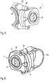
- the control element 2 has a three-part housing.
- the lower housing part 22 has a concave inner surface 221 with which the lower housing part 22 can rest against a handlebar tube 17. This allows a safe assembly, so that the control element 2 is protected against twisting, tilting and slipping.
- the middle housing part 26 is provided for receiving a battery cell 283, for example a lithium-ion battery, an alkaline battery or a zinc-air battery. The penetration of moisture between the middle housing part 26 and the lower housing part 22 is prevented by a seal 27.
- a screw connection allows easy opening and closing, so that the battery 283 can be easily replaced.
- the upper housing part 23 has, on the one hand, a viewing window 21 through which light from a light-emitting diode 284 can reach the viewer. In this way, an operating status display can be implemented if the light-emitting diode 284 emits light of different colors or interrupted light with different flashing patterns. Furthermore, the upper housing part 23 has a push button 25, by means of which the driver can send control signals to the electronic module 6 when the vehicle is stationary or while driving.
- the control element 2 has a simple electronic circuit, which is arranged on a circuit board 281 and detects the pressing of the button 25 and carries the light-emitting diode 284 and supplies it with electrical energy.
- a second circuit board 282 is arranged below it, which carries a high-frequency interface in order to establish a radio connection to the electronic module 6. Due to the two-part design, the transmitting HF part of the circuit can be easily exchanged in order to meet different legal requirements in different countries or to allow adaptation to different transmission protocols.
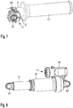
- the Figures 6 and 7 show the fastening of the control element 2 via a screw connection 261 with an optional clamp 222.
- the control element 2 can be positioned at any point on a handlebar tube 17.
- the control element 2 is advantageously located nearby a handle 171 so that the user can reach the button 25 without taking his hands off the handlebar. This allows safe operation of the bike and adjustment of the suspension system in any driving condition.
- FIG. 5 shows an alternative form of attachment to an existing mounting bracket 223.
- the mounting bracket 223 can be part of a brake and / or shift lever, which is already attached to the handlebar tube 17 in order to enable the actuation of a brake or a circuit.
- the operating element 2 can additionally be fastened to the clamp 223 via spacer bolts 224 and a screw connection 261, so that the use of a further clamp 222 is unnecessary. In this way, weight can be saved on the one hand and the reliability increased, since the notch effect of a further clamp 222 on the handlebar tube 17 is eliminated. Finally, the user has a tidy and attractive look.
- a spring element 4 is explained (not part of the invention).
- the same reference numerals designate the same components of the spring element 4 Figure 1 can be seen, the spring element 4 is provided for use on a sprung rear suspension or a rear wheel suspension.
- the spring element has a base body 42, in which an air chamber 421 is located.
- the piston 41 slides in the air chamber 421, the compressed air providing resistance to the piston 41.
- the base body and the piston can be fastened to the rear structure 15 or to the frame 10, so that the piston 41 deflects in the air chamber 421 as a function of the loads acting on the impellers 12.
- a coil spring for example made of steel, can also be used instead of the air chamber 421.
- the suspension behavior and / or the damping behavior and / or the available spring travel can be influenced by an actuating element 423.
- the user can adapt the response behavior of the rear wheel suspension to the respective operating state of the bicycle in a manner known per se, or temporarily block the suspension completely (lock-out).
- the shaft 432 is connected to an electric motor 431, which acts as an actuator in the exemplary embodiment shown.
- the control signal for the actuator 431 is generated in the electronics module 6 and transmitted via a radio link, which is provided by the HF board 482.
- a second circuit board 481 can decode the received signals and / or take up an H-bridge which energizes the electric motor 431.
- a battery 483 is available for supplying power to the electronic circuits 481 and 482 and the actuator 431. This can be recharged via a charging socket, which is accessible after removing the screw cap 45.
- the charge status of the battery 483 can be visualized in some embodiments via the operating status display 21 on the control element 2.
- the electronics modules 481, 482, the battery 483 and the actuator 431 can be accommodated in a housing 43 in a dustproof and splashproof manner, so that they are not impaired in the operation of the bicycle 1.
- the screw cap 45 can be provided with a seal 451 for a dustproof and splashproof seal.
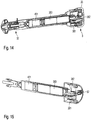
- FIG. 11 to 15 a spring element 3 described, which is intended for use on a suspension fork (not part of the invention).
- the spring element 3 is in a known manner in the standpipe 11 of the fork arranged and opposes the immersion in the dip tube 14 a defined resistance.
- the quality and quantity of this resistance characterize the suspension behavior of the fork and can be adjusted by means of an adjustment mechanism 32 in a manner known per se.
- the spring force, the damping force and / or the height of the fork or its unloaded zero position can be set by the user.
- an actuator 431 is again available, which can be, for example, an electric motor, a piezo actuator or a magnetic actuator.
- the actuator 431 is supplied with electrical energy by an accumulator 383.
- the electronics of the spring element 3 can contain a high-frequency part on a circuit board 382 and a control logic for the actuator 431 on a further circuit board 381. In other embodiments, however, all electronic components can also be arranged on a single circuit board.
- the in Figure 15 shown part with the actuator, the battery and the electronic circuit are removed after loosening the screw cap 35 from the fork in order to replace the accumulator 383 in this way.
- a charging socket 62 is available without further dismantling work, with which the accumulator 383 can be recharged during normal operation of the bicycle.
- the charge status of the accumulator 383 can also be monitored by the electronic module 6 and visualized with the operating status display 21.
- the suspension system thus offers the possibility, on the one hand, of changing the response behavior of the suspension system by manual user intervention in a previously known manner, but operational safety increases and the weight decreases due to the lack of Bowden cables and / or cabling.
- the electronic adjustment offers the advantage that the suspension on the front and rear wheels can be adjusted simultaneously.
- the suspension described can enable automatic driving operation based on the algorithms implemented in the software of the electronic module 6, in which the suspension behavior at the front and / or rear and / or the response of an optional sprung seat post 16 is fully automatically adapted to the respective operating state.
- the adaptation can take place as a function of the speed, the acceleration, the location, the terrain topography, the road surface and / or the applied torque.
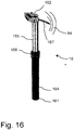
- FIG 16 shows an embodiment of the seat post according to the invention.
- the seat post 16 can be used for a bicycle, for example.
- the seat post 16 has a first end 161 which can be connected to a bicycle frame 10. The connection can be made with a clamp.
- the seat post 16 can have a second end 162 which can be connected to a saddle.
- a clamping bolt can be used, which in some embodiments also enables the inclination and / or a longitudinal adjustment of the saddle.
- the seat post 16 has at least one upper longitudinal section 165 and at least one lower longitudinal section 164, which engage in one another and are displaceable relative to one another along their longitudinal extent. The further the upper longitudinal section 165 engages in the lower longitudinal section 164, the deeper the setting of the saddle.
- the seat post has a fixing device 166, with which the two longitudinal sections 164, 165 in one predeterminable relative position can be fixed to each other.
- the fixing device 166 can be influenced by a radio signal 64.
- An optional antenna 167 is available for receiving the radio signal.
- the two longitudinal sections 164 and 165 are connected to one another via a gas pressure spring which is covered in the figures and is therefore not visible. When the fixing device 166 is released, the longitudinal section 165 therefore extends so that the seat height increases.
- the seat post according to the invention thus allows easy adjustment of the saddle height while driving, so that the seat height can be adapted to the respective driving condition.
- the radio signal 64 is generated with an operating element 2, the driver can keep both hands on the handlebars when adjusting the seat height, so that safe control of the bicycle is made possible.
- the radio signal 64 is generated by an electronics module 6, so that an automatic height adjustment depending on the driving state is made possible. If the seat post has a displacement sensor that reports the position of the seat post 16 to the electronic module 6, the electronic module 6 can in turn use this data to determine a control signal for the chassis components.
Landscapes
- Engineering & Computer Science (AREA)
- Mechanical Engineering (AREA)
- Axle Suspensions And Sidecars For Cycles (AREA)
Description
- Die Erfindung betrifft eine elektronisch gesteuerte Sattelstütze für ein Fahrrad, enthaltend zumindest ein Federelement, welches zwischen einem ersten Teil des Fahrrades und einem zweiten Teil des Fahrrades angeordnet ist, welche beweglich miteinander verbunden sind, wobei zumindest eine Kenngröße des Federelementes veränderbar ist, und zumindest einen Aktor, welcher auf das Federelement einwirkt, um die zumindest eine Kenngröße zu verändern, und ein Elektronikmodul, mit welchem ein Ansteuersignal für den zumindest einen Aktor erzeugbar ist.
- Aus der
US 6,050,583 ist bekannt, ein Fahrrad mit einer Federung auszustatten. Diese wird durch ein Ölbad bedämpft, indem das Öl durch eine Bohrung im Kolben einer Kolben-Zylinder-Paarung der Federung strömt. Weiterhin weist diese bekannte Federung einen mikromechanischen Beschleunigungssensor auf und einen Aktor, so dass durch Variieren der Öffnungen die Dämpfungskraft an die auf das Fahrrad einwirkende Beschleunigung angepasst werden kann. Beschleunigungssensor, Regelelektronik und Aktor sind über Kabelverbindungen miteinander verbunden. - Diese bekannte Vorrichtung weist den Nachteil auf, dass die Kabelverbindungen korrodieren können oder bei Geländeeinsatz des Fahrrades abreißen, so dass die Betriebssicherheit der Vorrichtung nur gering ist. Weiterhin kann mit dieser bekannten Vorrichtung zwar die Dämpfung angepasst werden, nicht jedoch die Federkraft, so dass eine Anpassung an unterschiedliche Fahrbedingungen nur rudimentär möglich ist.
- Aus
US 2011/204201 A1 ist bekannt, eine Sattelstütze mit Controller und mit einer Festlegevorrichtung im Einklang mit dem Oberbegriff des Anspruch 1. - Ausgehend von diesem Stand der Technik liegt der Erfindung die Aufgabe zugrunde, eine elektrische Sattelstütze für ein Fahrrad anzugeben, welche eine verbesserte Betriebssicherheit aufweist und/oder unterschiedliche Einstellmöglichkeiten bietet, so dass eine automatisierte Anpassung an unterschiedliche Betriebszustände möglich ist.
- Die Aufgabe wird erfindungsgemäß durch eine elektronisch gesteuerte Dattelstütze gemäß Anspruch 1 gelöst.
- Ein Federungssystem kann entweder nur am Vorderrad eines Fahrrades angeordnet sein. In anderen Ausführungsformen kann das Federungssystem sowohl am Vorder- als auch am Hinterrad angeordnet sein. In selteneren Ausführungsformen kann das Federungssystem auch nur am Hinterrad angeordnet sein. In wiederum einer anderen Ausführungsform kann das Federungssystem in einer Sattelstütze und/oder in einem Gabelschaft angeordnet sein. Die Aufgabe des Federungssystems besteht einerseits darin, den Fahrkomfort für den Benutzer des Fahrrades zu erhöhen. Darüber hinaus kann das Federungssystem eine verbesserte Haftung der Räder auf dem Untergrund ermöglichen, so dass die Traktion verbessert sein kann und/oder höhere Lenk- oder Bremskräfte übertragen werden können. Hierdurch kann die Fahrsicherheit oder die Geländegängigkeit des Fahrrades positiv beeinflusst werden.
- Das Fahrrad kann in einigen Ausführungsformen ein muskelgetriebenes, zweirädriges Fahrzeug sein, beispielsweise ein Mountainbike, ein Trekkingrad oder ein Straßenrennrad. In einigen Ausführungsformen kann das Fahrrad drei Räder aufweisen, also beispielsweise zwei Vorder- und ein Hinterrad oder ein Vorder- und zwei Hinterräder. In einigen Ausführungsformen kann das Fahrrad einen Elektromotor aufweisen, welcher das Fahrrad entweder zumindest zeitweise alternativ zum muskelbetriebenen Tretantrieb antreibt oder welches den Fahrer beim Treten unterstützt. Hierdurch kann das Fahrrad bei gleichem Energieeinsatz des Fahrers eine höhere Geschwindigkeit und/oder eine größere Reichweite erreichen und/oder steilere Anstiege bewältigen.
- Das Fahrrad weist zumindest ein Federelement auf, welches zwischen einem ersten Teil des Fahrrades und einem zweiten Teil des Fahrrades angeordnet ist, welche beweglich miteinander verbunden sind. Beispielsweise kann der erste, unbewegliche Teil des Fahrrades der Rahmen des Fahrrades sein oder die Standrohre einer Gabel oder der mit dem Rahmen verbindbare Teil einer Sattelstütze. Der zweite, bewegliche Teil des Fahrrades kann durch die Tauchrohre einer Gabel gebildet sein oder durch eine beweglich gelagerte Hinterbaukinematik eines Hinterradfederungssystems oder der mit dem Sattel verbindbare Teil einer Sattelstütze. Sowohl das Eigengewicht des Fahrrades, das Gewicht des Benutzers als auch dynamisch einwirkende Stöße auf die Laufräder führen zu einer relativen Bewegung zwischen dem ersten Teil und dem zweiten Teil des Fahrrades. Das Federelement wirkt dieser Bewegung entgegen.
- Das Federelement kann in einigen Ausführungsformen der eine Blattfeder oder einer Schraubenfeder enthalten, beispielsweise aus Stahl. In anderen Ausführungsformen der kann das Federelement eine Luftfeder umfassen, d.h. eine Kolben-Zylinder-Paarung, welche ein geschlossenes Luftvolumen einschließt, welches bei Einwirken externer Kräfte komprimiert wird. Weiterhin kann das Federelement eine Einrichtung zur Erzeugung einer Dämpfungskraft aufweisen, beispielsweise ein Ölvolumen, welches durch Öffnungen eines Kolbens strömt.
- Durch einen mechanischen Eingriff in Bauteile des Federelementes kann zumindest eine Kenngröße des Federelementes veränderbar sein. Durch Veränderung des Federelementes kann das Fahrverhalten des mit dem Federelement ausgestatteten Fahrrades verändert werden, beispielsweise kann die Energiedissipation in der Federung reduziert sein oder das Ansprechverhalten an unterschiedliche Untergründe angepasst werden. Die beeinflussbare Kenngröße des Federelementes kann ausgewählt sein aus der Federkraft der Druckstufe und/oder der Dämpfungskraft und/oder dem Federweg und/oder dem Lock-out, d.h. einer Festlegevorrichtung, mit welcher die Federung vollständig blockiert werden kann. Hierzu kann das Federelement mit einem Betätigungshebel und/oder einem Einstellrad ausgestattet sein, welcher in an sich bekannter Weise die mechanischen Eingriffe am Federelement vornimmt, um die gewünschten Änderungen durchzuführen. Die mechanischen Eingriffe können beispielsweise das Öffnen oder Schließen eines Ventils umfassen oder die Veränderung der Vorspannung einer Feder oder das Verändern der lichten Weite von zumindest einer Öffnung oder das Anlegen eines elektrischen Feldes oder das Anlgen eines Magnetfeldes.
- Es wird nun vorgeschlagen, das Bedienelement des Federelementes über zumindest einen Aktor zu betätigen, welcher auf das Federelement einwirkt, um die zumindest eine Kenngröße zu verändern.
- Der Aktor wird mit einem Ansteuersignal betätigt, welches beispielsweise ein pulsweitenmoduliertes elektrisches Signal sein kann. In anderen Ausführungsformen kann das Ansteuersignal ein analoges Strom- oder Spannungssignal sein. Dieses kann entweder die Ein- und Ausschaltzeit eines Aktors bestimmen oder dessen Absolutposition. Das Ansteuersignal wird durch ein Elektronikmodul erzeugt.
- Das Elektronikmodul erzeugt das Ansteuersignal in Abhängigkeit von zumindest einer Eingangsgröße, welche mit zumindest einem Steuerelement erzeugbar ist. Das Steuerelement kann die Eingangsgröße entweder in Abhängigkeit es Fahrerwunsches erzeugen oder automatisiert aus Messwerten, welche den jeweiligen Betriebszustand des Fahrrads erfassen.
- Es wird nun vorgeschlagen, das Steuerelement mit dem Elektronikmodul bevorzugt über ein Funksignal zu verbinden und/oder den Aktor mit dem Elektronikmodul über ein Funksignal zu verbinden. Hierdurch wird eine Verkabelung am Fahrradrahmen eingespart, so dass einerseits Gewicht eingespart werden kann und andererseits eine zuverlässige Übertragung der Signale ermöglicht wird, da eine Beschädigung des Kabels unmöglich ist. Das Funksignal kann digital oder analog codiert sein. In einigen Ausführungsformen kann das Funksignal im Frequenzband um 433 MHz gewählt sein. In anderen Ausführungsformen kann das Funksignal im Frequenzband um 2,4 GHz gewählt sein. Das Funksignal kann verschlüsselt werden, so dass eine Störung unterschiedlicher, nebeneinander fahrender Fahrräder vermieden wird. Weiterhin kann das elektronisch gesteuerte Fahrwerk nicht von außen manipuliert werden, wenn das Funksignal verschlüsselt ist. Die Verschlüsselung kann mit an sich bekannten Kryptographieverfahren erfolgen, beispielsweise AES, WPA, WEP oder anderen Verfahren. Das Funksignal kann eine an sich bekannte Schnittstelle realisieren, z.B. WLAN oder Bluetooth oder Near-Field-Communication (NFC).
- In einigen Ausführungsformen kann das Steuerelement ein Bedienelement und/oder einen Lagesensor und/oder einen Positionssensor und/oder einen Beschleunigungssensor enthalten. Über das Bedienelement kann der Benutzer des Fahrrades manuell eingreifen und beispielsweise die Federung blockieren oder die Dämpfungskraft und/oder den Federweg an ein gewünschtes Dämpfungsverhalten anpassen. In anderen Ausführungsformen kann das Steuerelement einen Lagesensor enthalten, welcher beispielsweise eine Seitenneigung des Fahrrades bei Kurvenfahrt detektiert und/oder Steigung und Gefälle erkennt, so dass bei Abfahrten eine weichere Federkennlinie gewählt werden kann und in Anstiegen mit großen Pedalkräften eine härtere Federkennlinie gewählt werden kann, um unbeabsichtigtes Wippen des Fahrwerkes zu vermeiden oder zu reduzieren. Zum gleichen Zweck kann auch ein optionaler Drehmomentsensor eingesetzt werden, welcher die vom Fahrer aufgebrachte Pedalkraft erkennt. In einigen Ausführungsformen kann das Steuerelement alternativ oder zusätzlich einen Positionssensor enthalten, mit welchem die Position des Fahrrades auf der Erdoberfläche erkennbar ist. In einigen Ausführungsformen kann der Positionssensor ein Funknavigationssystem sein oder enthalten, beispielsweise GPS, Glonass, Compass oder Galileo. Zur Erhöhung der Genauigkeit kann der Positionssensor auch zusätzliche terrestrische Funksignale empfangen und verarbeiten. Zusätzliche terrestrische Funksignale können ausgewählt sein aus Differential-GPS oder einem Mobilfunksignal wie GSM, LTE oder UMTS.
- In einigen Ausführungsformen der Erfindung kann das Steuerelement ein Mobiltelefon enthalten oder aus einem Mobiltelefon bestehen. Das Mobiltelefon kann mit einer an sich bekannten Funkverbindung, wie beispielsweise Bluetooth, mit dem Elektronikmodul verbunden werden. In anderen Ausführungsformen der Erfindung kann das Mobiltelefon mit einer Kabelverbindung mit dem Elektronikmodul verbunden sein, beispielsweise über eine USB-Schnittstelle. Über die Benutzerschnittstelle des Mobiltelefons kann das System mittels Benutzereingriffen geregelt bzw. gesteuert werden und/oder das Elektronikmodul kann aktuelle Konfigurationsdaten über das Display des Mobiltelefons ausgeben. Dazu kann auf dem Mobiltelefon eine Software ausgeführt werden, welche die Benutzereingaben in ein Ansteuersignal übersetzt. In einigen Ausführungsformen kann das Mobiltelefon über eine GSM-Schnittstelle, über eine GPRS-Schnittstelle, über eine LTE-Schnittstelle oder eine vergleichbare Schnittstelle Softwareupdates oder Konfigurationsdaten oder topographische Informationen aus einem Onlinespeicher abrufen und dem Elektronikmodul zur Verfügung stellen oder eine Sicherheitskopie des Speicherinhaltes des Elektronikmoduls auf dem Onlinespeicher ablegen.
- In einigen Ausführungsformen der Erfindung kann das Elektronikmodul ein Mobiltelefon enthalten oder aus einem Mobiltelefon bestehen. Das Mobiltelefon kann mit einer an sich bekannten Funkverbindung, wie beispielsweise Bluetooth, mit den Aktoren und/oder zumindest einem Steuerelement verbunden werden. In einigen Ausführungsformen der Erfindung kann das Mobiltelefon zusätzlich als Bedienelement verwendet werden. Dadurch kann Gewicht eingespart werden, da kein separates Elektronikmodul und/oder Bedienelement am Fahrrad verbaut werden muss. Auch die Stromversorgung des Elektronikmoduls und ein GPS-System zur Ortung sowie ein Speicher für Topographiedaten kann eingespart werden, wenn das Mobiltelefon mit diesen Komponenten ausgestattet ist. Der Akkumulator des Mobiltelefons wird vom Benutzer ohnehin regelmäßig aufgeladen, so dass ein separates Laden der Elektronikeinheit des Fahrrades entfallen kann. In anderen Ausführungsformen der Erfindung kann ein zusätzliches Bedienelement am Fahrradlenker befestigt sein, welches beispielsweise über eine Funkschnittstelle oder eine kabelgebundene Schnittstelle mit dem Mobiltelefon verbunden ist. Diese Ausführungsform hat den Vorteil, dass das Mobiltelefon stoß- und staubgeschützt mitgeführt werden kann, beispielsweise im Rucksack, und dennoch ein unmittelbarer Zugriff des Benutzers auf das Federungssystem bestehen bleibt und der Benutzer über den Zustand des Systems informiert werden kann.
- In einigen Ausführungsformen kann das Elektronikmodul einen Kartenspeicher zur Aufnahme topographischer Informationen enthalten. Die topographischen Informationen können einen Straßenverlauf repräsentieren oder einen Fahrbahnbelag, um so automatisch aus der Position des Fahrrades und der gewählten Fahrtroute eine stets optimale Anpassung der Kenngrößen der Federelemente zu gewährleisten, ohne dass der Fahrer manuell eingreifen muss. So kann beispielsweise vor einer Kurve eine härtere Federkennlinie gewählt werden oder auf befestigten Straßen kann eine härtere Federkennlinie gewählt werden als auf einer Schotterstrecke. Ebenso können die topographischen Informationen Höhendaten enthalten, so dass die Kenngröße der Federelemente in Abhängigkeit von Anstieg oder Gefälle entsprechend gewählt werden kann.
- In einigen Ausführungsformen kann das Federungssystem einen Geschwindigkeitssensor enthalten, welcher die Anpassung der Kenngröße zumindest eines Federelementes in Abhängigkeit der Fahrgeschwindigkeit erlaubt. In einigen Ausführungsformen kann der Geschwindigkeitssensor im Positionssensor integriert sein, welcher gleichzeitig Orts- und Geschwindigkeitsdaten ausgibt. Erfindungsgemäß enthält das Steuerelement einen Beschleunigungssensor, so dass bei großer Beschleunigung, welche eine entsprechende Kraft auf das Antriebsrad aufbringt, durch das Elektronikmodul die Federelemente so eingestellt werden können, dass die aufgebrachte Energie des Fahrers möglichst effektiv umgesetzt wird.
- Das Elektronikmodul kann in einigen Ausführungsformen einen Mikroprozessor oder einen Mikrocontroller enthalten, um aus der Eingangsgröße ein Ansteuersignal zu erzeugen. Hierzu kann eine Software verwendet werden, welche ein neuronales Netz implementiert und/oder eine Fuzzy-Logik und/oder ein Steuer- bzw. Regelverfahren. Hierdurch ist sichergestellt, dass aus einer Vielzahl von Eingangsgrößen, welche teilweise auch unscharfe oder widersprüchliche Informationen geben können, stets ein optimales Ansteuersignal zur optimalen Einstellung der Federelemente gewonnen werden kann.
- In einigen Ausführungsformen kann das Verfahren zur Steuerung der Federelemente einen selbstlernenden Algorithmus aufweisen, so dass durch Benutzereingriffe das Elektronikmodul die Vorlieben des Benutzers des Fahrrades erkennt und die Kenngrößen der Federelemente entsprechend wählt, so dass nach längerer Benutzung des Fahrrades durch einen Benutzer die Anzahl der Benutzereingriffe reduziert sein kann. Sofern das Fahrrad von mehreren Benutzern verwendet wird, kann das Elektronikmodul eine Mehrzahl von Speicherbereichen enthalten, so dass für unterschiedliche Benutzer unterschiedliche Kenndaten abgelegt werden können, so dass sich das Fahrverhalten des Fahrrades auch an mehrere unterschiedliche Benutzer anpassen kann.
- Erfindungsgemäß enthält der Beschleunigungssensor einen dreiachsigen mikromechanischen Sensor oder besteht aus einem solchen. Dies ermöglicht einen kompakten, zuverlässigen kostengünstigen Aufbau des vorgeschlagenen Federungssystems, wobei der Sensor in einigen Ausführungsformen zusammen mit dem Elektronikmodul auf einer Leiterplatte integriert sein kann.
- Erfindungsgemäß ist der mikromechanische Sensor ein dreiachsiger Sensor, welcher eine Beschleunigung in drei Achsen erkennen kann. Hierdurch kann sowohl eine geradlinige Beschleunigung bzw. ein Abbremsen des Fahrrades erkannt werden als auch eine Querbeschleunigung, welche bei Kurvenfahrt auftritt. Schließlich kann erkannt werden, ob das Fahrrad mit der Erdbeschleunigung oder einem Wert nahe der Erdbeschleunigung in Richtung auf den Boden beschleunigt wird. In diesem Fall ist das Fahrrad vollständig in der Luft, beispielsweise bei Sprüngen, so dass die Kennlinie des Federungssystems auf den mit der Landung verbundenen harten Stoß eingestellt werden kann.
- Erfindungsgemäß ist der mikromechanische Sensor ein dreiachsiger Sensor, welcher eine Beschleunigung in drei Achsen erkennen kann. Durch Integration der Beschleunigung über die Zeit kann eine Geschwindigkeit in allen drei Raumrichtungen bzw. die zeitliche Änderung der Lage im Raum durch die Elektronikeinheit bestimmt werden. Durch Integration der Geschwindigkeit über die Zeit kann die Lage des Fahrrades im Raum bestimmt werden. Aus diesen Daten lassen sich mit nur einem dreiachsigen mikromechanischen Sensor eine Vielzahl von Fahrzuständen erkennen. Wenn das Fahrrad nach hinten geneigt ist, d.h. das Vorderrad ist höher als das Hinterrad, so fährt der Fahrer bergauf. In diesem Fall kann eine härtere Federkennlinie gewählt oder die Federung blockiert oder eine höhenverstellbare Sattelstütze in eine hohe Position gebracht oder eine absenkbare Federgabel in eine untere, abgesenkte Position gebracht werden. Wenn das Fahrrad nach vorne geneigt ist, d.h. das Vorderrad ist tiefer als das Hinterrad, so fährt der Fahrer bergab. In diesem Fall kann eine weichere Federkennlinie gewählt oder die blockierte Federung wieder frei gegeben oder eine höhenverstellbare Sattelstütze in eine tiefe Position gebracht oder eine absenkbare Federgabel in eine obere Position gebracht werden. Wenn das Fahrrad eine Seitenneigung aufweist, durchfährt der Fahrer eine Kurve. In diesem Fall kann eine härtere Federkennlinie gewählt oder die Federung blockiert werden. Wenn sich die Seitenneigung zyklisch ändert und/oder die Beschleunigung in Fahrtrichtung größer als ein vorgebbarer Grenzwert ist, fährt der Fahrer im Wiegetritt. In diesem Fall kann eine härtere Federkennlinie gewählt oder die Federung blockiert werden.
- In einigen Ausführungsformen kann das Bedienelement zusammen mit einem Bremshebel und/oder einem Schalthebel an einem gemeinsamen Befestigungselement angeordnet sein. Hierdurch wird die Anzahl der Klemmschellen am Lenker reduziert, so dass einerseits eine gute Erreichbarkeit des Bedienelementes gegeben ist und andererseits die Gefahr der Beschädigung des Lenkerrohres durch Klemmschellen minimiert ist.
- In einigen Ausführungsformen kann der Aktor ausgewählt sein aus einem Elektromotor und/oder einem Magnetsteller und/oder einem Piezosteller und/oder einem Steller, welcher eine Formgedächtnislegierung enthält oder daraus besteht. Ein Elektromotor kann ein Schrittmotor sein, welcher kontrolliert drehbar ist und/oder ein Getriebemotor, welcher an seiner Außenseite eine geringere Drehzahl bereitstellt als der Rotor. Ein Getriebemotor kann ein Schneckengetriebe aufweisen. Dieses ist selbsthemmend, so dass eine einmal gewählte Position ohne weiteren Stromverbrauch beibehalten werden kann. Ein Elektromotor weist den Vorteil auf, dass der Stromverbrauch nur gering ist, da der Elektromotor nur dann bestromt werden muss, wenn tatsächlich eine Veränderung der Kenngrößen der Federelemente vorgenommen wird. Zur Bestromung des Elektromotors kann eine H-Brückenschaltung eingesetzt werden. Ein Magnetsteller und ein Piezosteller weisen den Vorteil auf, dass diese sehr schnelle Veränderungen der Kenngrößen der Federelemente vornehmen können, so dass eine rasche Anpassung an dynamische Fahrzustände möglich ist.
- Ein Aktor, welcher eine Formgedächtnislegierung enthält oder daraus besteht kann in einigen Ausführungsformen dazu eingesetzt werden, auf den Verschluss eines Ventiles einzuwirken, so dass eine Ventilöffnung geschlossen oder geöffnet oder deren lichter Querschnitt beeinflusst werden kann. Hierdurch kann das Durchströmen eines Fluides wie Luft oder Öl beeinflusst werden. Dies kann zur Beeinflussung der Dämpfungskraft oder zur völligen Blockierung der Federung führen (Lockout). In einer weiteren Ausführungsform kann durch ein Drehventil eine Ventilöffnung geschlossen oder geöffnet oder deren lichter Querschnitt beeinflusst werden. Der Antrieb des Drehventils kann über einen Elektromotor oder ein Element aus einer Formgedächtnislegierung erfolgen.
- In einigen Ausführungsformen kann die Dämpfungskraft zumindest eines Federelementes durch eine elektrorheologische Flüssigkeit eingestellt werden, deren Viskosität sich in Abhängigkeit eines elektrischen Feldes ändert. In diesem Fall kann der Aktor eine oder mehrere Elektroden aufweisen, welche nach Art eines Platten- oder Ringkondensators das im Dämpfungselement befindliche Öl bzw. die elektroriologische Flüssigkeit einem elektrischen Feld aussetzen.
- In einigen Ausführungsformen der Erfindung kann das Elektronikmodul zumindest einen ersten Betriebszustand und zumindest einen zweiten Betriebszustand aufweisen, wobei im zweiten Betriebszustand gegenüber dem ersten Betriebszustand die Anzahl ausführbarer Funktionen reduziert und der Energieverbrauch vermindert ist. Hierdurch kann die Lebensdauer der Batterie im Elektronikmodul vergrößert sein, da nur dann die volle Funktionsvielfalt und der volle Energieverbrauch zur Verfügung stehen, wenn das Fahrrad tatsächlich bewegt wird. Die Anzahl ausführbarer Funktionen im zweiten Betriebszustand, welcher auch als Energiesparzustand bezeichnet sein kann, kann soweit reduziert werden, dass die Komponenten lediglich die Benutzung des Fahrrades überwachen, um wieder in den ersten Betriebszustand zurück zu schalten. Auf diese Weise kann, ohne dass der Benutzer aktiv das System einschalten muss, eine stetige Verfügbarkeit sichergestellt werden, ohne dass die Batterien rasch, beispielsweise über Nacht, entladen sind. Das Umschalten des Betriebszustandes kann durch einen mikromechanischen Beschleunigungssensor erfolgen, welcher dann in den zweiten Betriebszustand schaltet, wenn während einer vorgebbaren Zeit keine Beschleunigung registriert wird und welcher in den ersten Betriebszustand schaltet, wenn erstmals wieder eine Beschleunigung registriert wird.
- In einigen Ausführungsformen kann das Steuerelement und/oder das Elektronikmodul zumindest eine Betriebszustandsanzeige enthalten. In einigen Ausführungsformen kann die Betriebszustandsanzeige zumindest eine LED und/oder zumindest ein LCD-Display enthalten. Bevorzugt, aber nicht zwingend, ist die Betriebszustandsanzeige in einem Bedienelement angeordnet, welches am Lenker des Fahrrades befestigt ist oder auf dem Display eines Mobiltelefons. Hierdurch ist die Betriebszustandsanzeige im Blickfeld des Fahrers. Die Betriebszustandsanzeige kann beispielsweise den aktuell anliegenden Betriebszustand bzw. die aktuell gewählten Kenngrößen der Federelemente anzeigen. Darüber hinaus kann die Betriebszustandsanzeige eine Warnung bei niedrigem Batteriestand ausgeben. Schließlich kann die Betriebszustandsanzeige dazu eingerichtet sein, das Aushandeln einer Funkfrequenz und/oder eines Sendeprotokolls zwischen dem Steuerelement und dem Elektronikmodul anzuzeigen oder zu unterstützen.
- In einigen Ausführungsformen kann die zu verändernde Kenngröße der Federelemente ausgewählt sein aus einer Federkraft und/oder einer Dämpfungskraft und/oder einem Federweg und/oder einer Nulllage. Beispielsweise kann der Federweg auf befestigten Fahrbahnen bis auf Null reduziert werden, so dass sich ein sicheres Fahrverhalten und eine unmittelbare Umsetzung der eingebrachten Antriebsleistung im Vortrieb ergibt. Auf schlechteren Fahrbahnen kann der Federweg einstufig oder mehrstufig vergrößert werden, bis der volle Federweg auf sehr unebenem Untergrund zur Verfügung steht.
- In einigen Ausführungsformen kann die Federkraft angepasst werden, so dass sich ein eher komfortables Ansprechen oder ein eher festes Ansprechen der Federelemente ergibt.
- Schließlich kann die Nulllage angepasst werden, d.h. die Position der Federelemente bei unbelastetem Fahrwerk. So kann bei Bergauffahrt beispielsweise eine Federgabel abgesenkt werden, um eine günstigere Gewichtsverteilung zu ermöglichen. Bei Bergabfahrt kann die Gabelabsenkung wieder aufgehoben werden, um den vollen Federweg zur Verfügung zu haben.
- Nachfolgend soll die Erfindung anhand von Figuren ohne Beschränkung des allgemeinen Erfindungsgedankens näher erläutert werden. Dabei zeigt
- Figur 1
- ein Ausführungsbeispiel eines Fahrrades.
- Figur 2
- zeigt ein Blockschaltbild der verwendeten elektronischen Komponenten.
- Figur 3
- zeigt eine Ansicht eines Bedienelementes.
- Figur 4
- zeigt das Bedienelement im Schnitt.
- Figur 5
- zeigt eine mögliche Montage des Bedienelementes.
- Figur 6
- zeigt eine zweite mögliche Montage des Bedienelementes.
- Figur 7
- zeigt ein Bedienelement mit einem Teil eines Lenkerrohres.
- Figur 8
- zeigt ein Federelement gemäß einer ersten Ausführungsform in der Ansicht.
- Figur 9
- zeigt das Federelement gemäß der ersten Ausführungsform im Schnitt.
- Figur 10
- zeigt einen Ausschnitt aus
Figur 9 . - Figur 11
- zeigt eine zweite Ausführungsform eines Federelementes in einer ersten Ansicht.
- Figur 12
- zeigt eine zweite Ausführungsform des Federelementes in einem ersten Schnitt.
- Figur 13
- zeigt die zweite Ausführungsform des Federelementes in einer zweiten Ansicht.
- Figur 14
- zeigt eine zweite Ausführungsform des Federelementes in einem zweiten Schnitt.
- Figur 15
- zeigt ein Detail des Federelementes gemäß der zweiten Ausführungsform im Schnitt.
- Figur 16
- zeigt eine Ausführungsform der erfindungsgemäßen Sattelstütze.
-
Figur 1 zeigt ein Fahrrad 1 gemäß einer Ausführungsform. Das Fahrrad 1 weist einen Rahmen 10 auf, welcher für die Zwecke der nachfolgenden Beschreibung einen ersten, feststehenden Teil des Fahrrades repräsentiert. Der Rahmen 10 trägt in an sich bekannter Weise über eine Sattelstütze 16 einen Sattel sowie eine Tretkurbel, mit welcher ein Benutzer eine Antriebskraft erzeugen kann. Die Antriebskraft bzw. das Drehmoment kann über einen Drehmomentsensor 5 erfasst werden. Über eine Kette und eine optionale Schaltung wird die Antriebkraft auf das hintere Laufrad 12 übertragen. - Die Sattelstütze 16 ist höhenverstellbar, so dass der Fahrer bergauf oder in der Ebene eine hohe Sitzposition einnehmen kann, welche eine bessere und ergonomische Kraftübertragung auf die Tretkurbel erlaubt. Bei Bergabfahrt kann die Sattelstütze eingefahren werden, so dass sich eine tiefe Sitzposition mit günstiger Schwerpunktlage ergibt. Die Höhenverstellung der Sattelstütze kann wie bei einem Bürostuhl über eine Gasdruckfeder oder eine Stahlfeder erfolgen, so dass der Fahrer die Höhenverstellung während der Fahrt vornehmen kann und nicht absteigen muss. Das Auslösen der Höhenverstellung kann über ein Bedienelement am Lenker erfolgen, welches über eine Hydraulik oder einen Bowdenzug mit der Sattelstütze verbunden ist. Erfindungsgemäß erfolgt das Auslösen der Höhenverstellung über ein Funksignal. Das Funksignal kann beispielsweise über ein Bedienelement am Lenker abgesetzt werden, so dass ein Bowdenzug oder eine Hydraulikleitung nicht erforderlich ist. In anderen Ausführungsformen kann das Funksignal von der Elektronikeinheit in Abhängigkeit des Fahrzustandes abgesetzt werden, so dass neben der jeweils optimalen Einstellung von zumindest einem Federelement auch die Sattelhöhe automatisiert eingestellt wird.
- Das Fahrrad 1 weist zwei Laufräder 12 auf. Das vordere Laufrad 12 ist an einer Federgabel drehbar gelagert, um das Fahrrad 1 zu lenken. Die Federgabel weist Standrohre 11 auf, welche im Wesentlichen unbeweglich mit dem Rahmen 10 verbunden sind sowie Tauchrohre 14, in welche die Standrohre 11 beim Einfedern des Vorderrades eintauchen. Die dem Eintauchen entgegengesetzte Kraft wird durch ein Federelement 3 erzeugt, welches anhand der
Figuren 11 bis 15 näher beschrieben wird. Zum Lenken des Fahrrades 1 dient ein Lenkerrohr 17, welches auch ein Bedienelement 2 trägt, so dass der Benutzer über die Betriebsparameter des Systems informiert werden kann und/oder manuell die Kenngrößen der Federelemente 3 und 4 beeinflussen kann. - Das hintere Laufrad 12 ist an einem beweglichen Hinterbau 15 angeordnet. Die beim Einfedern bzw. bei Belastung auf den Rahmen 10 übertragenen Kräfte werden vom Federelement 4 aufgenommen. Die dabei dem einfedernden Hinterrad entgegengesetzten Kräfte werden durch die Kenngrößen des Federelementes 4 definiert, welches anhand der
Figuren 8 bis 10 näher erläutert wird. - Schließlich ist an der Sattelstütze 16 ein Elektronikmodul 6 montiert, welches die Ansteuersignale für die in den Federelementen 3 und 4 befindlichen Aktoren erzeugt. Das Bedienelement 2, der Drehmomentsensor 5 und die Federelemente 3 und 4 sind über ein Funksignal 64 mit dem Elektronikmodul 6 verbunden. Dadurch kann einerseits Gewicht für Kabelverbindungen oder Bowdenzüge eingespart werden und andererseits eine hohe Betriebssicherheit sichergestellt werden, da weder elektrische Anschlusskontakte korrodieren können noch das Kabel mechanisch beschädigt werden kann. In einigen Ausführungsformen der Erfindung kann das Elektronikmodul 6 und/oder das Bedienelement 2 als Mobiltelefon ausgestaltet sein, auf welchem eine entsprechend angepasste Software ausgeführt wird. Hierdurch wird ein dediziertes, mit dem Fahrrad verbundenes Elektronikmodul eingespart.
-
Figur 2 zeigt ein Blockschaltbild des Elektronikmoduls 6 und weiterer peripherer Komponenten. Das Elektronikmodul 6 enthält einen Mikroprozessor CPU, auf welchem ein Computerprogramm ausgeführt wird, welches aus Eingangsgrößen der Sensoren ein Ansteuersignal für die Aktoren errechnet. Das Computerprogramm kann in einem EEPROM 65 oder einem Flash-Speicher abgelegt sein, so dass die jeweiligen Daten auch beim Abschalten oder bei Tiefentladung der Batterie 61 nicht verlorengehen. Daneben kann der Flash-Speicher Konfigurationsdaten enthalten, beispielsweise Benutzervorlieben oder Topographiedaten, beispielsweise digitalisierte Landkarten mit Höheninformationen und/oder Informationen über die Fahrbahnbeschaffenheit. Daten können dem Mikroprozessor und den Speichern 65 über eine serielle Schnittstelle GPIO oder SPI und/oder einen Analog-Digital-Wandler ADC zugeführt werden. Diese Daten können Softwareupdates oder Topographiedaten enthalten, welche beispielsweise über eine USB-Schnittstelle 62 zugeführt werden können. Diese kann optional auch zum Laden des Akkumulators 61 eingesetzt werden. In anderen Ausführungsformen kann hierzu eine separate Ladeschnittstelle vorhanden sein oder der Akkumulator 61 wird nach dessen Entleerung ersetzt bzw. außerhalb des Elektronikmoduls 6 geladen. Die Spannung und/oder der dem Akku 61 entnommene Strom kann über den Analog-Digital-Wandler ADC von dem Mikroprozessor CPU überwacht werden. Hierdurch kann das Fahrwerk bei entladenem Akkumulator 61 in ein Notprogramm gebracht werden. In einigen Ausführungsformen kann das Elektronikmodul 6 mit der CPU, dem EEPROM 65, dem Speicher 65, der seriellen Schnittstelle GPIO oder SPI, der USB-Schnittstelle 62 und dem Akkumulator 61 in Form eines Mobiltelefons bzw. eines Smartphones oder eines Tablet-Computers ausgestaltet sein. - Schließlich kann das Elektronikmodul 6 einen Beschleunigungssensor 63 enthalten, mit welchem die Änderung der Fahrgeschwindigkeit und/oder eine Kurvendurchfahrt erkennbar ist. In anderen Ausführungsformen kann der Beschleunigungssensor 63 auch in einer separaten Baugruppe am Fahrrad 1 angebracht sein oder Teil des Bedienelementes 2 sein und seine Daten über ein Funksignal 64 weiterleiten. Analog wie für den Beschleunigungssensor 63 beschrieben, kann das Elektronikmodul 6 auch einen Lagesensor, einen Geschwindigkeitssensor oder einen Positionssensor enthalten. In
Figur 2 ist der Positionssensor 66 als separate Baugruppe ausgebildet, welche über ein Funksignal 64 mit dem Elektronikmodul 6 verbunden ist. Erfindungsgemäß ist ein dreiachsiger Beschleunigungssensor vorhanden, aus dessen Daten durch Integration über die Zeit ein Geschwindigkeitsvektor und ein Lagevektor berechnet werden können. Zur Bestimmung eines Koordinatennullpunktes kann eine Initialisierung erfolgen, indem das Fahrrad auf einem ebenen Platz aufrecht abgestellt wird und nachfolgend diese Position als horizontale Ruhelage abgespeichert wird. Alle weiteren Positionen, wie z.B. Seitenneigung, Bergauffahrt, Bergabfahrt und die aktuelle Geschwindigkeit ergeben sich daraus durch Integration der Beschleunigungen in allen drei Raumrichtungen. Sofern das Fahrrad bei der Initialisierung nicht aufrecht steht, sondern beispielsweise mit erhöhtem Vorder- oder Hinterrad, kann auch ein abeichender Koordinatennullpunkt durch den Fahrer gewählt werden. Dies erlaubt eine individuelle Feinabstimmung. - Schließlich zeigt
Figur 2 , wie ein Bedienelement 2 über ein Funksignal 64 mit dem Elektronikmodul 6 verbunden werden kann. Das Bedienelement 2 selbst wird nachfolgend anhand derFiguren 3 bis 7 näher erläutert. Das Elektronikmodul 6 gemäßFigur 2 enthält weiter eine Betriebszustandsanzeige 21. In anderen Ausführungsformen kann diese Bestandteil des Bedienelementes 2 sein oder in einem Federelement 3 oder 4 integriert sein. - Das Elektronikmodul 6 kann eine optionale H-Brücke zur Motoransteuerung enthalten, wenn der Aktor 431 zumndest einen Elektromotor enthält. In anderen Ausführungsformen kann der Elektromotor 431 zusammen mit der H-Brücke auch Bestandteil des Federelementes 3 oder 4 sein, so dass diese Bestandteile nicht im Elektronikmodul 6 integriert sein müssen.
- Die
Figuren 3 bis 7 zeigen eine Ausführungsform eines Bedienelementes 2. Dabei sind gleiche Teile mit gleichen Bezugszeichen versehen, so dass zur Vermeidung von Wiederholungen nicht sämtliche Bauteile im Zusammenhang mit allen Figuren erläutert werden. - Das Bedienelement 2 weist im dargestellten Ausführungsbeispiel ein dreiteiliges Gehäuse auf. Dabei weist das untere Gehäuseteil 22 eine konkave Innenfläche 221 auf, mit welcher der untere Gehäuseteil 22 an einem Lenkerrohr 17 anliegen kann. Dies erlaubt eine sichere Montage, so dass das Bedienelement 2 vor Verdrehen, Verkippen und Verrutschen geschützt ist. Der mittlere Gehäuseteil 26 ist zur Aufnahme einer Batteriezelle 283 vorgesehen, beispielsweise eine Lithiumionenbatterie, einer Alkalibatterie oder einer Zink-Luft-Batterie. Das Eindringen von Feuchtigkeit zwischen dem mittleren Gehäuseteil 26 und dem unteren Gehäuseteil 22 wird durch eine Dichtung 27 verhindert. Eine Schraubverbindung erlaubt leichtes Öffnen und Schließen, so dass die Batterie 283 einfach gewechselt werden kann. Der obere Gehäuseteil 23 weist einerseits ein Sichtfenster 21 auf, durch welches Licht einer Leuchtdiode 284 den Betrachter erreichen kann. Hierdurch kann eine Betriebszustandsanzeige realisiert werden, wenn die Leuchtdiode 284 Licht unterschiedlicher Farben oder unterbrochenes Licht mit unterschiedlichen Blinkmustern aussendet. Weiterhin weist das obere Gehäuseteil 23 einen Druckknopf 25 auf, durch welchen der Fahrer im Stand oder während der Fahrt Steuersignale an das Elektronikmodul 6 senden kann. Hierzu weist das Bedienelement 2 eine einfache elektronische Schaltung auf, welche auf einer Platine 281 angeordnet ist und das Drücken des Tasters 25 erkennt sowie die Leuchtdiode 284 trägt und mit elektrischer Energie versorgt.
- Darunter ist eine zweite Platine 282 angeordnet, welche ein Hochfrequenz-Interface trägt, um eine Funkverbindung zum Elektronikmodul 6 herzustellen. Durch die zweiteilige Ausführung kann der sendende HF-Teil der Schaltung leicht ausgetauscht werden, um unterschiedliche gesetzliche Bestimmungen in unterschiedlichen Ländern zu erfüllen oder eine Anpassung an unterschiedliche Sendeprotokolle zu ermöglichen.
- Die
Figuren 6 und7 zeigen die Befestigung des Bedienelementes 2 über eine Verschraubung 261 mit einer optionalen Schelle 222. Hierdurch kann das Bedienelement 2 an einer beliebigen Stelle eines Lenkerrohres 17 positioniert werden. Vorteilhaft befindet sich das Bedienelement 2 in der Nähe eines Griffes 171, so dass der Benutzer den Taster 25 erreichen kann, ohne die Hände vom Lenker zu nehmen. Dies erlaubt eine sichere Bedienung des Fahrrades und eine Einstellung des Federungssystems in jedem Fahrzustand. -
Figur 5 zeigt eine alternative Befestigungsform an einer vorhandenen Befestigungsschelle 223. Die Befestigungsschelle 223 kann Bestandteil eines Brems- und/oder Schalthebels sein, welcher ohnehin bereits am Lenkerrohr 17 befestigt ist, um die Betätigung einer Bremse oder einer Schaltung zu ermöglichen. Das Bedienelement 2 kann über Abstandsbolzen 224 und eine Verschraubung 261 zusätzlich an der Schelle 223 befestigt werden, so dass die Verwendung einer weiteren Schelle 222 entbehrlich ist. Hierdurch kann einerseits Gewicht eingespart werden als auch die Zuverlässigkeit erhöht werden, da die Kerbwirkung einer weiteren Schelle 222 auf das Lenkerrohr 17 entfällt. Schließlich ergibt sich für den Benutzer eine aufgeräumte und attraktive Optik. - Anhand der
Figuren 8 bis 10 wird eine Ausführungsform eines Federelementes 4 erläutert (nicht zur Erfindung gehörend). Auch in diesem Fall bezeichnen gleiche Bezugszeichen gleiche Bestandteile des Federelementes 4. Wie ausFigur 1 ersichtlich, ist das Federelement 4 zum Einsatz an einem gefederten Hinterbau bzw. einer Hinterradfederung vorgesehen. Das Federelement weist einen Grundkörper 42 auf, in welchem sich eine Luftkammer 421 befindet. Der Kolben 41 gleitet in der Luftkammer 421, wobei die komprimierte Luft dem Kolben 41 einen Widerstand entgegensetzt. Mit den Befestigungsösen 422 und 411 können Grundkörper und Kolben am Hinterbau 15 bzw. am Rahmen 10 befestigt werden, so dass der Kolben 41 in Abhängigkeit der auf die Laufräder 12 einwirkenden Belastungen in der Luftkammer 421 einfedert. In anderen Ausführungsformen kann statt der Luftkammer 421 auch eine Schraubenfeder eingesetzt sein, beispielsweise aus Stahl. - Das Federungsverhalten und/oder das Dämpfungsverhalten und/oder der zur Verfügung stehende Federweg kann in einigen Ausführungsformen durch ein Betätigungsglied 423 beeinflusst werden. Hierdurch kann der Benutzer in an sich bekannter Weise das Ansprechverhalten der Hinterradfederung an den jeweiligen Betriebszustand des Fahrrades anpassen oder die Federung zeitweise komplett blockieren (Lock-Out).
- Es wird vorgeschlagen, das Betätigungsglied 423 über den Nocken 433 einer Welle 432 zu betätigen. Die Welle 432 ist mit einem Elektromotor 431 verbunden, welcher im dargestellten Ausführungsbeispiel als Aktor wirkt. Das Ansteuersignal für den Aktor 431 wird im Elektronikmodul 6 erzeugt und über eine Funkverbindung übertragen, welche durch die HF-Platine 482 bereitgestellt wird. Eine zweite Platine 481 kann die empfangenen Signale decodieren und/oder eine H-Brücke aufnehmen, welche den Elektromotor 431 bestromt. Zur Energieversorgung der elektronischen Schaltungen 481 und 482 sowie des Aktors 431 steht eine Batterie 483 zur Verfügung. Diese kann über eine Ladebuchse wieder aufgeladen werden, welche nach Abnehmen der Schraubkappe 45 zugänglich wird. Der Ladezustand der Batterie 483 kann in einigen Ausführungsformen über die Betriebszustandsanzeige 21 am Bedienelement 2 visualisiert werden.
- Die Elektronikmodule 481, 482, die Batterie 483 und der Aktor 431 können in einem Gehäuse 43 staub- und spritzwasserdicht untergebracht sein, so dass diese im Betrieb des Fahrrades 1 nicht beeinträchtigt werden. Für einen staubund spritzwasserdichten Abschluss kann der Schraubdeckel 45 mit einer Dichtung 451 versehen sein.
- Schließlich wird anhand der
Figuren 11 bis 15 ein Federelement 3 beschrieben, welches zum Einsatz an einer Federgabel vorgesehen ist (nicht zur Erfindung gehörend). Das Federelement 3 ist in an sich bekannter Weise im Standrohr 11 der Gabel angeordnet und setzt dem Eintauchen in das Tauchrohr 14 einen definierten Widerstand entgegen. Qualität und Quantität dieser Widerstandskraft charakterisieren das Federungsverhalten der Gabel und können durch eine Verstellmechanik 32 in an sich bekannter Weise eingestellt werden. Hierdurch kann die Federkraft, die Dämpfungskraft und/oder die Höhe der Gabel bzw. deren unbelastete Nulllage vom Benutzer eingestellt werden. Auch dies kann vorliegend entweder durch Benutzereingriff über das Bedienelement 2 bzw. dem darauf angeordneten Taster 25 erfolgen, oder automatisiert, indem das Elektronikmodul 2 in Abhängigkeit der Eingangsgrößen der optional vorhandenen Sensorik eine jeweils passende Charakteristik auswählt. Um den Verstellmechanismus 32 automatisiert zu bewegen, steht wiederum ein Aktor 431 zur Verfügung, welcher beispielsweise ein Elektromotor sein kann, ein Piezosteller oder ein Magnetsteller. Der Aktor 431 wird ebenso wie die Elektronik 381 und 382 von einem Akkumulator 383 mit elektrischer Energie versorgt. Wie vorstehend beschrieben kann die Elektronik des Federelementes 3 einen Hochfrequenzteil auf einer Platine 382 enthalten sowie eine Ansteuerlogik für den Aktor 431 auf einer weiteren Platine 381. In anderen Ausführungsformen können alle Elektronikkomponenten jedoch auch auf einer einzigen Platine angeordnet sein. - Für Wartungsarbeiten kann der in
Figur 15 gezeigte Teil mit dem Aktor, der Batterie und der elektronischen Schaltung nach Lösen der Schraubkappe 35 aus der Gabel entfernt werden, um auf diese Weise beispielsweise den Akkumulator 383 auszutauschen. Darüber hinaus steht nach Lösen der Schraubkappe 35 ohne weitere Demontagearbeiten eine Ladebuchse 62 zur Verfügung, mit welcher der Akkumulator 383 im Normalbetrieb des Fahrrades wieder aufgeladen werden kann. Auch der Ladezustand des Akkumulators 383 kann vom Elektronikmodul 6 überwacht werden und mit der Betriebszustandsanzeige 21 visualisiert werden. - Das Federungssystem bietet somit einerseits die Möglichkeit, durch manuellen Benutzereingriff in bisher bekannter Weise das Ansprechverhalten des Federungssystems zu verändern, wobei jedoch aufgrund fehlender Bowdenzüge und/oder Verkabelung die Betriebssicherheit steigt und das Gewicht sinkt. Die elektronische Verstellung bietet dabei den Vorteil, dass die Federung an Vorder- und Hinterrad gleichzeitig verstellt werden kann. Weiterhin kann die beschriebene Federung aufgrund der in der Software des Elektronikmoduls 6 implementierten Algorithmen einen automatischen Fahrbetrieb ermöglichen, bei welchem das Federungsverhalten vorne und/oder hinten und/oder das Ansprechen einer optionalen gefederten Sattelstütze 16 an den jeweiligen Betriebszustand vollautomatisch angepasst wird. Die Anpassung kann dabei in Abhängigkeit der Geschwindigkeit, der Beschleunigung, der Lage, der Geländetopographie, der Fahrbahnbeschaffenheit und/oder des aufgebrachten Drehmomentes erfolgen.
-
Figur 16 zeigt eine Ausführungsform der erfindungsgemäßen Sattelstütze. Die Sattelstütze 16 ist beispielsweise für ein Fahrrad verwendbar. Die Sattelstütze 16 weist ein erstes Ende 161 auf, welches mit einem Fahrradrahmen 10 verbindbar ist. Die Verbindung kann mit einer Klemmung erfolgen. Weiterhin kann die Sattelstütze 16 ein zweites Ende 162 aufweisen, welches mit einem Sattel verbindbar ist. Hierzu kann ein Klemmbolzen verwendet werden, welcher in einigen Ausführungsformen auch eine Einstellung der Neigung und/oder eine Längsverstellung des Sattels ermöglicht. Die Sattelstütze 16 weist zumindest einen oberen Längsabschnitt 165 und zumindest einen unteren Längsabschnitt 164 auf, welche ineinandergreifen und entlang ihrer Längserstreckung relativ zueinander verschiebbar sind. Je weiter der obere Längsabschnitt 165 in den unteren Längs-abschnitt 164 eingreift, um so tiefer ist die Einstellung des Sattels. Weiterhin weist die Sattelstütze eine Festlegevorrichtung 166 auf, mit welcher die zwei Längsabschnitte 164, 165 in einer vorgebbaren relativen Lage zueinander fixiert werden können. Die Festlegevorrichtung 166 ist durch ein Funksignal 64 beeinflussbar. Zum Empfang des Funksignals steht eine optionale Antenne 167 zur Verfügung. - Die zwei Längsabschnitte 164 und 165 sind über eine Gasdruckfeder miteinander verbunden, welche in den Figuren verdeckt und daher nicht sichtbar ist. Beim Lösen der Festlegevorrichtung 166 fährt daher der Längsabschnitt 165 aus, so dass sich die Sitzhöhe vergrößert. Die erfindungsgemäße Sattelstütze erlaubt somit ein einfaches Verstellen der Sattelhöhe während der Fahrt, so dass die Sitzhöhe an den jeweiligen Fahrtzustand angepasst werden kann. Wenn das Funksignal 64 mit einem Bedienelement 2 erzeugt wird, kann der Fahrer bei der Verstellung der Sitzhöhe beide Hände am Lenker lassen, so dass eine sichere Kontrolle über das Fahrrad ermöglicht wird. Erfindungsgemäß wird das Funksignal 64 von einem Elektronikmodul 6 erzeugt, so dass eine automatische Höhenverstellung in Abhängigkeit des Fahrzustandes ermöglicht wird. Sofern die Sattelstütze einen Weggeber aufweist, welcher die Position der Sattelstütze 16 an das Elektronikmodul 6 meldet, kann das Elektronikmodul 6 diese Daten wiederum zur Ermittlung eines Ansteuersignals für die Fahrwerkskomponenten verwenden.
Claims (10)
- Sattelstütze (16) für ein Fahrrad, mit einem ersten Ende (161), welches mit einem Fahrradrahmen (10) verbindbar ist und einem zweiten Ende (162), welches mit einem Sattel verbindbar ist, wobei die Sattelstütze (16) zumindest zwei Längsabschnitte (164, 165) aufweist, welche ineinandergreifen und entlang ihrer Längserstreckung relativ zueinander verschiebbar sind, wobei die Sattelstütze weiterhin eine Festlegevorrichtung (166) aufweist, mit welcher die zwei Längsabschnitte (164, 165) in einer vorgebbaren relativen Lage zueinander fixiert werden können,
dadurch gekennzeichnet, dass
die Festlegevorrichtung (166) durch ein Funksignal (64) beeinflussbar ist, welches von einem Elektronikmodul (6) erzeugt werden kann, so dass eine automatische Höhenverstellung in Abhängigkeit des Fahrzustandes ermöglicht wird, wobei das Elektronikmodul (6) einen dreiachsigen mikromechanischen Beschleunigungsensor enthält. - Sattelstütze nach Anspruch 1, weiterhin enthaltend eine Antenne, mit welcher das Funksignal empfangbar ist.
- Sattelstütze nach Anspruch 1 oder 2, dadurch gekennzeichnet, dass das Funksignal (64) durch ein Bedienelement (2) erzeugbar ist.
- Sattelstütze nach Anspruch 1, dadurch gekennzeichnet, dass das Funksignal (64) von dem Elektronikmodul (6) in Abhängigkeit der Geländetopographie erzeugbar ist.
- Sattelstütze nach einem der Ansprüche 1 bis 4, dadurch gekennzeichnet, dass das Elektronikmodul (6) und/oder das Bedienelement (2) ein Mobiltelefon enthält oder daraus besteht.
- Sattelstütze nach einem der Ansprüche 1 bis 5, dadurch gekennzeichnet, dass das Elektronikmodul (6) dazu eingerichtet ist, eine Geschwindigkeit und/oder eine Lage durch Integration der Daten des dreiachsigen mikromechanischen Beschleunigungssensors über die Zeit zu bestimmen.
- Sattelstütze nach einem der Ansprüche 1 bis 6, dadurch gekennzeichnet, dass das Elektronikmodul (6) zumindest einen ersten Betriebszustand und zumindest einen zweiten Betriebszustand aufweist, wobei im zweiten Betriebszustand gegenüber dem ersten Betriebszustand die Anzahl ausführbarer Funktionen reduziert und der Energieverbrauch vermindert ist.
- Sattelstütze nach Anspruch 7, dadurch gekennzeichnet, dass das Elektronikmodul (6) dazu eingerichtet ist, vom ersten Betriebszustand in den zweiten Betriebszustand zu schalten, wenn über eine vorgebbare Zeit keine Beschleunigung erfasst wird und/oder
dass das Elektronikmodul (6) dazu eingerichtet ist, vom zweiten Betriebszustand in den ersten Betriebszustand zu schalten, wenn eine Beschleunigung erfasst wird. - Sattelstütze nach einem der Ansprüche 1 bis 8, dadurch gekennzeichnet, dass das Elektronikmodul (6) dazu eingerichtet ist, zusätzlich zur Position der Sattelstütze auch zumindest ein Federungselement am Vorder- und/oder Hinterrad zu beeinflussen.
- Sattelstütze nach einem der Ansprüche 1 bis 9, dadurch gekennzeichnet, dass die zwei Längsabschnitte (164, 165) über eine Gasdruckfeder miteinander verbunden sind.
Priority Applications (1)
| Application Number | Priority Date | Filing Date | Title |
|---|---|---|---|
| EP17156524.5A EP3192731B1 (de) | 2012-08-21 | 2013-08-20 | Elektronisch gesteuertes federungssystem, verfahren zur steuerung eines federungssystems und computerprogramm |
Applications Claiming Priority (3)
| Application Number | Priority Date | Filing Date | Title |
|---|---|---|---|
| DE201210214867 DE102012214867A1 (de) | 2012-08-21 | 2012-08-21 | Elektronisch gesteuertes Federungssystem, Verfahren zur Steuerung eines Federungssystems und Computerprogramm |
| DE102012215062 | 2012-08-24 | ||
| PCT/EP2013/067286 WO2014029759A1 (de) | 2012-08-21 | 2013-08-20 | Elektronisch gesteuertes federungssystem, verfahren zur steuerung eines federungssystems und computerprogramm |
Related Child Applications (2)
| Application Number | Title | Priority Date | Filing Date |
|---|---|---|---|
| EP17156524.5A Division EP3192731B1 (de) | 2012-08-21 | 2013-08-20 | Elektronisch gesteuertes federungssystem, verfahren zur steuerung eines federungssystems und computerprogramm |
| EP17156524.5A Division-Into EP3192731B1 (de) | 2012-08-21 | 2013-08-20 | Elektronisch gesteuertes federungssystem, verfahren zur steuerung eines federungssystems und computerprogramm |
Publications (3)
| Publication Number | Publication Date |
|---|---|
| EP2888157A1 EP2888157A1 (de) | 2015-07-01 |
| EP2888157B1 EP2888157B1 (de) | 2017-03-01 |
| EP2888157B2 true EP2888157B2 (de) | 2020-08-05 |
Family
ID=49000498
Family Applications (2)
| Application Number | Title | Priority Date | Filing Date |
|---|---|---|---|
| EP13750585.5A Active EP2888157B2 (de) | 2012-08-21 | 2013-08-20 | Elektronisch gesteuertes federungssystem, verfahren zur steuerung eines federungssystems und computerprogramm |
| EP17156524.5A Active EP3192731B1 (de) | 2012-08-21 | 2013-08-20 | Elektronisch gesteuertes federungssystem, verfahren zur steuerung eines federungssystems und computerprogramm |
Family Applications After (1)
| Application Number | Title | Priority Date | Filing Date |
|---|---|---|---|
| EP17156524.5A Active EP3192731B1 (de) | 2012-08-21 | 2013-08-20 | Elektronisch gesteuertes federungssystem, verfahren zur steuerung eines federungssystems und computerprogramm |
Country Status (4)
| Country | Link |
|---|---|
| US (2) | US9592882B2 (de) |
| EP (2) | EP2888157B2 (de) |
| TW (2) | TWI600572B (de) |
| WO (1) | WO2014029759A1 (de) |
Families Citing this family (105)
| Publication number | Priority date | Publication date | Assignee | Title |
|---|---|---|---|---|
| EP1799534B1 (de) | 2004-09-15 | 2014-08-27 | Yeti Cycling LLC | Hinterradaufhängungssystem für ein fahrrad |
| US11306798B2 (en) | 2008-05-09 | 2022-04-19 | Fox Factory, Inc. | Position sensitive suspension damping with an active valve |
| US9452654B2 (en) | 2009-01-07 | 2016-09-27 | Fox Factory, Inc. | Method and apparatus for an adjustable damper |
| US10047817B2 (en) * | 2009-01-07 | 2018-08-14 | Fox Factory, Inc. | Method and apparatus for an adjustable damper |
| US20100170760A1 (en) | 2009-01-07 | 2010-07-08 | John Marking | Remotely Operated Bypass for a Suspension Damper |
| US9239090B2 (en) | 2009-01-07 | 2016-01-19 | Fox Factory, Inc. | Suspension damper with remotely-operable valve |
| US9033122B2 (en) | 2009-01-07 | 2015-05-19 | Fox Factory, Inc. | Method and apparatus for an adjustable damper |
| US8857580B2 (en) | 2009-01-07 | 2014-10-14 | Fox Factory, Inc. | Remotely operated bypass for a suspension damper |
| US8627932B2 (en) | 2009-01-07 | 2014-01-14 | Fox Factory, Inc. | Bypass for a suspension damper |
| US10060499B2 (en) | 2009-01-07 | 2018-08-28 | Fox Factory, Inc. | Method and apparatus for an adjustable damper |
| US8393446B2 (en) | 2008-08-25 | 2013-03-12 | David M Haugen | Methods and apparatus for suspension lock out and signal generation |
| US9140325B2 (en) | 2009-03-19 | 2015-09-22 | Fox Factory, Inc. | Methods and apparatus for selective spring pre-load adjustment |
| US12491961B2 (en) | 2008-11-25 | 2025-12-09 | Fox Factory, Inc. | Seat post |
| US10036443B2 (en) | 2009-03-19 | 2018-07-31 | Fox Factory, Inc. | Methods and apparatus for suspension adjustment |
| US9422018B2 (en) * | 2008-11-25 | 2016-08-23 | Fox Factory, Inc. | Seat post |
| EP2189191B1 (de) | 2008-11-25 | 2016-02-24 | Fox Factory, Inc. | Verfahren und Vorrichtung für virtuelle Wettbewerbe |
| US11299233B2 (en) | 2009-01-07 | 2022-04-12 | Fox Factory, Inc. | Method and apparatus for an adjustable damper |
| US10821795B2 (en) | 2009-01-07 | 2020-11-03 | Fox Factory, Inc. | Method and apparatus for an adjustable damper |
| US12122205B2 (en) | 2009-01-07 | 2024-10-22 | Fox Factory, Inc. | Active valve for an internal bypass |
| US9038791B2 (en) | 2009-01-07 | 2015-05-26 | Fox Factory, Inc. | Compression isolator for a suspension damper |
| US8936139B2 (en) | 2009-03-19 | 2015-01-20 | Fox Factory, Inc. | Methods and apparatus for suspension adjustment |
| US8672106B2 (en) | 2009-10-13 | 2014-03-18 | Fox Factory, Inc. | Self-regulating suspension |
| US8955653B2 (en) | 2009-10-13 | 2015-02-17 | Fox Factory, Incorporated | Methods and apparatus for controlling a fluid damper |
| US10697514B2 (en) | 2010-01-20 | 2020-06-30 | Fox Factory, Inc. | Remotely operated bypass for a suspension damper |
| EP2402239B1 (de) | 2010-07-02 | 2020-09-02 | Fox Factory, Inc. | Einstellbare Sattelstütze |
| US9102378B2 (en) | 2010-08-20 | 2015-08-11 | Yeti Cycling, Llc | Link suspension system |
| US9821879B2 (en) | 2010-08-20 | 2017-11-21 | Yeti Cycling, Llc | Reciprocating rail movement suspension system |
| US9216791B2 (en) * | 2011-03-14 | 2015-12-22 | Christopher Hudec | Bicycle suspension system |
| EP2530355B1 (de) | 2011-05-31 | 2019-09-04 | Fox Factory, Inc. | Vorrichtungen für lageempfindliche und/oder anpassbare Aufhängungsdämpfung |
| EP2567839B1 (de) | 2011-09-12 | 2019-03-13 | Fox Factory, Inc. | Verfahren und Vorrichtung zur Aufhängungseinstellung |
| US11279199B2 (en) | 2012-01-25 | 2022-03-22 | Fox Factory, Inc. | Suspension damper with by-pass valves |
| US10330171B2 (en) | 2012-05-10 | 2019-06-25 | Fox Factory, Inc. | Method and apparatus for an adjustable damper |
| US10766563B2 (en) | 2013-01-16 | 2020-09-08 | Yeti Cyclying, Llc | Rail suspension with integral shock and dampening mechanism |
| TWI507318B (zh) * | 2014-07-31 | 2015-11-11 | Giant Mfg Co Ltd | 自行車自動調整阻尼系統 |
| DE102014004698B3 (de) * | 2014-03-31 | 2015-08-06 | Matthias Ebel | Beleuchtung für ein zumindest teilweise muskelbetriebenes Fahrzeug bzw. dessen Anhänger mittels Lichtführungselementen, gesteuert durch ein mobiles Endgerät bzw. Smartphone oder durch eine zentrale Lichtquelle |
| DE102014209472A1 (de) * | 2014-05-20 | 2015-11-26 | Robert Bosch Gmbh | Federgabelanordnung und Verfahren zur Einstellung eines Parameters einer Federgabel eines Zweirades |
| US10363992B2 (en) | 2015-01-29 | 2019-07-30 | Shimano Inc. | Electric bicycle component |
| US9399500B1 (en) * | 2015-03-04 | 2016-07-26 | Shimano Inc. | Bicycle wireless control system |
| US11801913B2 (en) * | 2015-03-05 | 2023-10-31 | Shimano Inc. | Bicycle electric component setting system |
| DE102015205596A1 (de) | 2015-03-27 | 2016-09-29 | Gustav Magenwirth Gmbh & Co. Kg | Elektronisch gesteuertes Federungssystem, Verfahren zu dessen Betrieb und Diagnosegerät |
| US9840294B2 (en) * | 2015-03-27 | 2017-12-12 | Shimano Inc. | Controlling bicycle component according to seat position |
| JP6649014B2 (ja) * | 2015-08-28 | 2020-02-19 | 株式会社シマノ | 自転車用制御装置およびこの制御装置を備える自転車用駆動装置 |
| US10150526B2 (en) * | 2015-10-16 | 2018-12-11 | Specialized Bicycle Components, Inc. | Bicycle saddle post suspension |
| WO2017168467A1 (ja) * | 2016-03-30 | 2017-10-05 | 川崎重工業株式会社 | 鞍乗型車両の情報出力装置 |
| US10737546B2 (en) | 2016-04-08 | 2020-08-11 | Fox Factory, Inc. | Electronic compression and rebound control |
| CN105857451A (zh) * | 2016-06-13 | 2016-08-17 | 京东方科技集团股份有限公司 | 一种智能自行车 |
| US11161565B2 (en) | 2016-08-05 | 2021-11-02 | Shimano Inc. | Bicycle control device and bicycle electric assist unit including bicycle control device |
| CN107421561A (zh) * | 2016-09-21 | 2017-12-01 | 王禄愚 | 通用型自行车减震器监测及数据分析系统 |
| JP2018069858A (ja) * | 2016-10-26 | 2018-05-10 | 株式会社シマノ | 自転車用通信装置およびペアリングの方法 |
| US10358180B2 (en) | 2017-01-05 | 2019-07-23 | Sram, Llc | Adjustable seatpost |
| US10843757B2 (en) * | 2017-03-08 | 2020-11-24 | Shimano Inc. | Bicycle electric telescopic apparatus, bicycle power supply system, and bicycle electric component system |
| US12600431B2 (en) | 2017-03-17 | 2026-04-14 | Yeti Cycling, Llc | Vehicle suspension linkage |
| EP3595963A4 (de) | 2017-03-17 | 2021-03-10 | Yeti Cycling, LLC | Fahrzeugaufhängungsgelenk |
| JP6786435B2 (ja) * | 2017-04-06 | 2020-11-18 | 株式会社シマノ | 自転車用制御装置 |
| DE102017209811B3 (de) * | 2017-06-09 | 2018-07-26 | Robert Bosch Gmbh | Regelungsverfahren für ein Motordrehmoment eines Antriebsmotor eines Zweirads, Steuergerät und Zweirad |
| US10926830B2 (en) | 2017-07-07 | 2021-02-23 | Yeti Cycling, Llc | Vehicle suspension linkage |
| JP6929721B2 (ja) * | 2017-07-10 | 2021-09-01 | 株式会社シマノ | 自転車用制御装置、自転車用制御装置を含む電動補助ユニット、自転車用制御装置を含むサスペンション、および、自転車用制御装置を含むアジャスタブルシートポスト |
| JP7236799B2 (ja) | 2017-07-11 | 2023-03-10 | 株式会社シマノ | 自転車用制御装置およびこれを備える自転車用サスペンションシステム |
| US11001323B2 (en) | 2017-08-23 | 2021-05-11 | Shimano Inc. | Electric seatpost assembly |
| US12623748B2 (en) | 2017-09-28 | 2026-05-12 | Sram, Llc | Controllable cycle suspension |
| TWI661395B (zh) * | 2017-11-15 | 2019-06-01 | 拓連科技股份有限公司 | 車輛之停放位置管理系統及方法,及相關電腦程式產品 |
| JP6859249B2 (ja) * | 2017-11-16 | 2021-04-14 | 株式会社シマノ | 人力駆動車両用制御装置 |
| US10960955B2 (en) * | 2017-12-15 | 2021-03-30 | Sram, Llc | Bicycle electrical control device and system |
| CN109960267A (zh) * | 2017-12-25 | 2019-07-02 | 亚帝发工业股份有限公司 | 立车稳定及倾斜辅助的参数建构系统及其控制流程 |
| TWI649222B (zh) * | 2017-12-25 | 2019-02-01 | 亞帝發工業股份有限公司 | 立車穩定及傾斜輔助之具體架構 |
| TWI649221B (zh) * | 2017-12-25 | 2019-02-01 | 亞帝發工業股份有限公司 | 立車穩定及傾斜輔助之參數建構系統及其控制流程 |
| US11066118B2 (en) | 2018-01-26 | 2021-07-20 | Shimano Inc. | Bicycle seatpost system |
| US10450022B2 (en) | 2018-01-31 | 2019-10-22 | David Watson | Device for adjusting a seat position of a bicycle seat |
| US10604201B2 (en) | 2018-03-29 | 2020-03-31 | Shimano Inc. | Telescopic apparatus |
| ES2876300T3 (es) * | 2018-06-22 | 2021-11-12 | Orbea S Coop | Cuadro de bicicleta con amortiguador integrado |
| JP7347929B2 (ja) * | 2018-12-18 | 2023-09-20 | 株式会社シマノ | 人力駆動車用コンポーネント |
| US11731723B2 (en) | 2018-07-09 | 2023-08-22 | Shimano Inc. | Rider recognition device for human-powered vehicle and control system of human-powered vehicle |
| US11527981B2 (en) | 2018-07-09 | 2022-12-13 | Shimano Inc. | Human-powered vehicle control device, electronic device, and human-powered vehicle control system |
| US11597470B2 (en) | 2018-07-09 | 2023-03-07 | Shimano Inc. | Human-powered vehicle component, mobile electronic device, and equipment for human-powered vehicle |
| US11527980B2 (en) | 2018-07-09 | 2022-12-13 | Shimano Inc. | Electronic device and human-powered vehicle system |
| US10882582B2 (en) * | 2018-07-13 | 2021-01-05 | Shimano Inc. | Suspension control device for a human-powered vehicle |
| JP7545196B2 (ja) * | 2019-01-31 | 2024-09-04 | 株式会社シマノ | 制御装置、学習モデルの生成方法、学習モデル、コンピュータプログラム、および記憶媒体 |
| US12077241B2 (en) | 2019-02-01 | 2024-09-03 | Yeti Cycling, Llc | Multi-body vehicle suspension linkage |
| JP7626584B2 (ja) * | 2019-03-04 | 2025-02-07 | 株式会社シマノ | 評価装置、制御システム、報知システム、学習モデルの生成方法、コンピュータプログラム、および、記憶媒体 |
| TWI723397B (zh) * | 2019-03-19 | 2021-04-01 | 彥豪金屬工業股份有限公司 | 自行車後變速器 |
| USD914525S1 (en) * | 2019-05-28 | 2021-03-30 | Robert Bosch Gmbh | Remote for a display and operating device |
| DE102019211615B3 (de) * | 2019-08-02 | 2021-02-04 | Robert Bosch Gmbh | Verfahren zum Regeln einer Höhe einer unbelastet verstellbaren Sattelstütze eines Zweirades und eine Höhenverstelleinrichung zum unbelasteten Verstellen einer Sattelstütze eines Zweirades |
| DE102019214614A1 (de) * | 2019-09-25 | 2021-03-25 | Zf Friedrichshafen Ag | Vorrichtung und Verfahren zur situationsangepassten Änderung des Schwerpunkts eines Fahrrads |
| JP7321873B2 (ja) | 2019-10-09 | 2023-08-07 | 株式会社シマノ | 人力駆動車用の制御装置 |
| JP7391602B2 (ja) * | 2019-10-15 | 2023-12-05 | 株式会社シマノ | 制御装置 |
| US20210131520A1 (en) * | 2019-11-01 | 2021-05-06 | Suspension Direct Inc. | Integrated electronic valving control for shock absorber |
| US11891146B2 (en) * | 2019-12-17 | 2024-02-06 | Sram, Llc | Bicycle suspension components and electronic monitoring devices |
| US11724769B2 (en) | 2019-12-17 | 2023-08-15 | Sram, Llc | Bicycle suspension components and electronic control devices |
| US12145684B2 (en) | 2019-12-24 | 2024-11-19 | Yeti Cycling, Llc | Constrained multiple instantaneous velocity center linkage assembly for vehicle suspension |
| DE102020100276A1 (de) * | 2020-01-09 | 2021-07-15 | Shimano Inc. | Federungssteuersystem für die federung eines mit menschenkraft angetriebenen fahrzeugs |
| TWI920083B (zh) | 2020-05-04 | 2026-04-01 | 加拿大商綠房控股有限公司 | 調整自行車座椅位置裝置以及調整自行車座椅之傾斜度的裝置 |
| US12062240B2 (en) * | 2020-09-17 | 2024-08-13 | VergeIQ, LLC | Monitoring system |
| US12384484B2 (en) | 2020-11-18 | 2025-08-12 | Yeti Cycling, Llc | Integrated motor mount and suspension pivot |
| DE102021208701A1 (de) * | 2021-08-10 | 2023-02-16 | Zf Friedrichshafen Ag | Federgabel mit Steuergerät |
| EP4396471A1 (de) * | 2021-08-31 | 2024-07-10 | SR SUNTOUR EUROPE GmbH | Kompressionsventil |
| EP4396070A1 (de) * | 2021-08-31 | 2024-07-10 | SR SUNTOUR EUROPE GmbH | Dämpfersteuerungsanordnung |
| US12617488B2 (en) | 2021-09-09 | 2026-05-05 | Yeti Cycling, Llc | Two-wheeled vehicle with configurable idler |
| DE202021105290U1 (de) | 2021-09-30 | 2023-01-10 | Canyon Bicycles Gmbh | Betätigungseinrichtung für ein höhenverstellbares Sattelstützrohr |
| TWI814155B (zh) * | 2021-11-29 | 2023-09-01 | 信邦電子股份有限公司 | 電動輔助自行車的輔助力控制系統與方法 |
| CN114408071B (zh) * | 2022-02-25 | 2023-07-18 | 广州凯斯博自行车有限公司 | 一种骑行脚踏顺畅度感应反馈系统 |
| US12064156B2 (en) | 2023-01-09 | 2024-08-20 | John F. Krumme | Dynamic compression fixation devices |
| TWI828145B (zh) * | 2022-05-12 | 2024-01-01 | 巧連科技股份有限公司 | 電動載具的雙向充電裝置 |
| JP2024074680A (ja) * | 2022-11-21 | 2024-05-31 | 株式会社シマノ | 人力駆動車用の制御方法、および、人力駆動車用の制御装置 |
| US12686465B2 (en) * | 2024-02-09 | 2026-07-21 | Shimano Inc. | Detection system, detection method, and computer-readable storage medium |
| TWI904811B (zh) * | 2024-08-15 | 2025-11-11 | 亞元科技股份有限公司 | 針對驅動車的處理裝置以及方法 |
Citations (3)
| Publication number | Priority date | Publication date | Assignee | Title |
|---|---|---|---|---|
| WO1998039201A1 (en) † | 1997-03-06 | 1998-09-11 | Rami Bonen | Bicycle seat |
| WO2011065759A2 (ko) † | 2009-11-26 | 2011-06-03 | Lee Chang-Yong | 자전거의 안장 높이 조절 장치 |
| US20110202236A1 (en) † | 2009-03-19 | 2011-08-18 | Mario Galasso | Methods and apparatus for suspension adjustment |
Family Cites Families (43)
| Publication number | Priority date | Publication date | Assignee | Title |
|---|---|---|---|---|
| FR2755529B1 (fr) | 1996-11-07 | 1999-02-05 | Mavic Sa | Systeme de commande et/ou de mesure a liaison sans fil pour cycle |
| US6050583A (en) | 1997-01-13 | 2000-04-18 | Bohn; David D. | Electronically controlled bicycle suspension apparatus |
| US6336648B1 (en) * | 1997-12-15 | 2002-01-08 | David D. Bohn | Electronically controlled anti-dive suspension apparatus for two-wheeled vehicles |
| DE19922745A1 (de) | 1999-05-18 | 2000-12-07 | Bayerische Motoren Werke Ag | Radaufhängungsvorrichtung für Motorräder |
| US6767308B2 (en) * | 2001-03-09 | 2004-07-27 | Shimano Inc. | Method of controlling bicycle assembly |
| DE60120103T2 (de) | 2001-03-13 | 2007-01-11 | Shimano Inc., Sakai City | Fahrradaufhängung |
| US6558180B2 (en) * | 2001-05-18 | 2003-05-06 | Shimano Inc. | Waterproof electrical connector |
| NL1018948C2 (nl) * | 2001-09-13 | 2003-03-20 | Sparta B V | Rijwiel met hulpaandrijving. |
| US6734376B2 (en) * | 2002-06-19 | 2004-05-11 | Shimano Inc. | Electrical switch device for bicycle |
| US6848930B2 (en) * | 2003-01-15 | 2005-02-01 | Shimano, Inc. | Electrical connector with resilient retaining ring to restrict radial expansion |
| JP2004256047A (ja) * | 2003-02-27 | 2004-09-16 | Shimano Inc | 自転車用距離表示システム及び距離表示装置 |
| JP3777360B2 (ja) * | 2003-03-27 | 2006-05-24 | 株式会社シマノ | 自転車用情報処理装置 |
| JP4437699B2 (ja) * | 2004-05-14 | 2010-03-24 | 富士通マイクロエレクトロニクス株式会社 | センサ |
| US7406367B2 (en) * | 2004-08-26 | 2008-07-29 | Shimano Inc. | Input circuit for bicycle component |
| US7254516B2 (en) * | 2004-12-17 | 2007-08-07 | Nike, Inc. | Multi-sensor monitoring of athletic performance |
| US20080119330A1 (en) * | 2006-11-22 | 2008-05-22 | Boson Technology Co., Ltd. | Intelligent vehicle meter |
| US20100228405A1 (en) * | 2007-06-13 | 2010-09-09 | Intrago Corporation | Shared vehicle management system |
| DE102008006051B4 (de) | 2008-01-25 | 2017-03-09 | Bayerische Motoren Werke Aktiengesellschaft | Feder-Dämpfersystem und Verfahren zur Steuerung oder Regelung des Feder- und/oder Dämpferverhaltens einer Feder-Dämpfereinrichtung eines einspurigen Kraftfahrzeugs |
| EP2189191B1 (de) | 2008-11-25 | 2016-02-24 | Fox Factory, Inc. | Verfahren und Vorrichtung für virtuelle Wettbewerbe |
| US9422018B2 (en) * | 2008-11-25 | 2016-08-23 | Fox Factory, Inc. | Seat post |
| TWM360841U (en) * | 2009-01-19 | 2009-07-11 | Dah Ken Ind Co Ltd | Electronic hydraulic damper control for bicycle damper |
| DE102009060999A1 (de) * | 2009-06-24 | 2011-01-05 | German Gresser | Energieoptimiertes Elektrofahrzeug mit autarker Stromversorgung und Verfahren zur Stromerzeugung, bevorzugt aus kinetischer und Gravitationsenergie |
| US8091910B2 (en) * | 2009-06-29 | 2012-01-10 | Shimano, Inc. | Apparatus for controlling a bicycle suspension element |
| AU2009100700B4 (en) * | 2009-07-02 | 2009-11-12 | Nanocycle Pty Ltd | Improvements to power assisted vehicles |
| US20130179016A1 (en) * | 2009-07-02 | 2013-07-11 | Stephen William Gale | Power Assisted Vehicles |
| TWI419808B (zh) * | 2009-09-04 | 2013-12-21 | Shimano Kk | 自行車座椅高度調整方法 |
| DE102009059801A1 (de) | 2009-12-21 | 2010-08-26 | Daimler Ag | Verfahren zur Steuerung und/oder Regelung eines aktiven Fahrwerks eines Fahrzeugs |
| US9511809B2 (en) * | 2010-02-23 | 2016-12-06 | Shimano Inc. | Height adjustable seatpost assembly |
| US8489277B2 (en) | 2010-04-14 | 2013-07-16 | Shimano Inc. | Electronic suspension control apparatus |
| US8655561B2 (en) * | 2010-06-23 | 2014-02-18 | Shimano Inc. | Bicycle control system having a value generating unit |
| EP2402239B1 (de) * | 2010-07-02 | 2020-09-02 | Fox Factory, Inc. | Einstellbare Sattelstütze |
| US8308124B2 (en) | 2010-10-28 | 2012-11-13 | Jung Yu Hsu | Control device for adjustable bicycle seat |
| US8317261B2 (en) * | 2010-11-03 | 2012-11-27 | Austin A. Walsh | Bicycle seat height adjusting assembly |
| WO2012059792A1 (en) | 2010-11-05 | 2012-05-10 | Crank Brothers, Inc. | Adjustable seat post assembly for bicycles |
| DE102010055828A1 (de) | 2010-12-23 | 2012-06-28 | Dt Swiss Ag | Fahrwerksteuerung für ein Fahrrad |
| DE102011009405A1 (de) | 2011-01-25 | 2012-07-26 | Dt Swiss Ag | Stoßdämpfer für Fahrrad |
| US9569966B2 (en) * | 2011-03-14 | 2017-02-14 | B-Cycle Llc | Bicycle tracking system with communication hub |
| US9284016B2 (en) * | 2011-03-31 | 2016-03-15 | Shimano Inc. | Bicycle component control apparatus |
| US8655548B2 (en) * | 2011-03-31 | 2014-02-18 | Shimano Inc. | Bicycle component control apparatus |
| US8723659B2 (en) * | 2012-07-10 | 2014-05-13 | Shimano Inc. | Bicycle gear shift indicator |
| JP2014231331A (ja) * | 2013-05-30 | 2014-12-11 | 株式会社シマノ | 操作装置 |
| US9229712B2 (en) * | 2013-09-10 | 2016-01-05 | Shimano Inc. | Bicycle component control apparatus |
| GB201512700D0 (en) * | 2014-08-01 | 2015-08-26 | Ford Global Tech Llc | Electric bicycle |
-
2013
- 2013-08-20 EP EP13750585.5A patent/EP2888157B2/de active Active
- 2013-08-20 WO PCT/EP2013/067286 patent/WO2014029759A1/de not_active Ceased
- 2013-08-20 EP EP17156524.5A patent/EP3192731B1/de active Active
- 2013-08-22 TW TW102130071A patent/TWI600572B/zh not_active IP Right Cessation
- 2013-08-22 TW TW106128916A patent/TWI637875B/zh not_active IP Right Cessation
-
2015
- 2015-02-20 US US14/627,158 patent/US9592882B2/en active Active
-
2016
- 2016-09-26 US US15/275,804 patent/US10259520B2/en active Active
Patent Citations (3)
| Publication number | Priority date | Publication date | Assignee | Title |
|---|---|---|---|---|
| WO1998039201A1 (en) † | 1997-03-06 | 1998-09-11 | Rami Bonen | Bicycle seat |
| US20110202236A1 (en) † | 2009-03-19 | 2011-08-18 | Mario Galasso | Methods and apparatus for suspension adjustment |
| WO2011065759A2 (ko) † | 2009-11-26 | 2011-06-03 | Lee Chang-Yong | 자전거의 안장 높이 조절 장치 |
Also Published As
| Publication number | Publication date |
|---|---|
| EP3192731B1 (de) | 2019-11-20 |
| US20150197308A1 (en) | 2015-07-16 |
| TWI600572B (zh) | 2017-10-01 |
| TW201412596A (zh) | 2014-04-01 |
| US9592882B2 (en) | 2017-03-14 |
| EP2888157A1 (de) | 2015-07-01 |
| TW201738138A (zh) | 2017-11-01 |
| US20170008584A1 (en) | 2017-01-12 |
| EP2888157B1 (de) | 2017-03-01 |
| TWI637875B (zh) | 2018-10-11 |
| EP3192731A1 (de) | 2017-07-19 |
| WO2014029759A1 (de) | 2014-02-27 |
| US10259520B2 (en) | 2019-04-16 |
Similar Documents
| Publication | Publication Date | Title |
|---|---|---|
| EP3192731B1 (de) | Elektronisch gesteuertes federungssystem, verfahren zur steuerung eines federungssystems und computerprogramm | |
| EP4370388B1 (de) | Verfahren zur bremsung eines fahrzeugs | |
| DE102017012150B3 (de) | Fahrradsteuereinrichtung | |
| EP2886433B1 (de) | Fahrwerksteuerung für ein Zweirad und Verfahren | |
| EP3095681B1 (de) | Fahrradkomponente, fahrrad und verfahren | |
| DE102013014091B4 (de) | Fahrwerksteuerung für ein Zweirad und Verfahren | |
| DE102017213606A1 (de) | Fahrradsteuervorrichtung und elektrische Fahrrad-Assistenzeinheit, enthaltend die Fahrradsteuervorrichtung | |
| EP2479095B1 (de) | Stossdämpfer für ein Fahrrad | |
| EP2679859B1 (de) | Stoßdämpfer und Verfahren zum Betreiben eines Stoßdämpfers insbesondere für ein Fahrrad | |
| DE102012004176A1 (de) | Integrierte Diebstahlsicherung für ein Elektrofahrrad | |
| DE102018104181A1 (de) | Fahrradelektrovorrichtung und Fahrraddrahtlossteuersystem | |
| DE102010055828A1 (de) | Fahrwerksteuerung für ein Fahrrad | |
| DE102018115407A1 (de) | Fahrradkomponentensteuersystem | |
| DE102019119273A1 (de) | Federungssteuervorrichtung für ein vom Menschen angetriebenes Fahrzeug | |
| DE202011104974U1 (de) | Fahrradrahmen | |
| DE102015107738B4 (de) | Zwei- oder Dreiradkomponente, Zwei- oder Dreirad und Verfahren | |
| DE102017130681B3 (de) | Vorspannlenkvorrichtung für einen Rollstuhl und Rollstuhlgespann mit Vorspannlenkvorrichtung | |
| EP3514047A1 (de) | Drahtlose bremssteuerung | |
| DE102012214867A1 (de) | Elektronisch gesteuertes Federungssystem, Verfahren zur Steuerung eines Federungssystems und Computerprogramm | |
| DE102012009203A1 (de) | Fahrzeug und Verfahren zum Unterstützen eines Fahrers eines Fahrzeugs beim Führen des Fahrzeugs auf einem hinteren Rad | |
| DE102019118277A1 (de) | Human-powered vehicle control device, electronic device and human-powered vehicle control system | |
| DE102013012702A1 (de) | Fahrrad | |
| EP2689996A1 (de) | Verfahren und Vorrichtung zur Steuerung einer Dämpfung eines Fahrrads | |
| DE102019118227A1 (de) | Federungssteuervorrichtung für ein mit menschenkraft angetriebenes fahrzeug | |
| DE102023200506A1 (de) | Verfahren und Assistenzsystem zur Anpassung einer Fahrradgeometrie eines mobilen Fahrrades |
Legal Events
| Date | Code | Title | Description |
|---|---|---|---|
| PUAI | Public reference made under article 153(3) epc to a published international application that has entered the european phase |
Free format text: ORIGINAL CODE: 0009012 |
|
| 17P | Request for examination filed |
Effective date: 20141218 |
|
| AK | Designated contracting states |
Kind code of ref document: A1 Designated state(s): AL AT BE BG CH CY CZ DE DK EE ES FI FR GB GR HR HU IE IS IT LI LT LU LV MC MK MT NL NO PL PT RO RS SE SI SK SM TR |
|
| AX | Request for extension of the european patent |
Extension state: BA ME |
|
| DAX | Request for extension of the european patent (deleted) | ||
| GRAP | Despatch of communication of intention to grant a patent |
Free format text: ORIGINAL CODE: EPIDOSNIGR1 |
|
| INTG | Intention to grant announced |
Effective date: 20160920 |
|
| GRAS | Grant fee paid |
Free format text: ORIGINAL CODE: EPIDOSNIGR3 |
|
| GRAA | (expected) grant |
Free format text: ORIGINAL CODE: 0009210 |
|
| AK | Designated contracting states |
Kind code of ref document: B1 Designated state(s): AL AT BE BG CH CY CZ DE DK EE ES FI FR GB GR HR HU IE IS IT LI LT LU LV MC MK MT NL NO PL PT RO RS SE SI SK SM TR |
|
| REG | Reference to a national code |
Ref country code: GB Ref legal event code: FG4D Free format text: NOT ENGLISH |
|
| REG | Reference to a national code |
Ref country code: CH Ref legal event code: EP Ref country code: AT Ref legal event code: REF Ref document number: 870923 Country of ref document: AT Kind code of ref document: T Effective date: 20170315 |
|
| REG | Reference to a national code |
Ref country code: IE Ref legal event code: FG4D Free format text: LANGUAGE OF EP DOCUMENT: GERMAN |
|
| REG | Reference to a national code |
Ref country code: DE Ref legal event code: R096 Ref document number: 502013006533 Country of ref document: DE |
|
| REG | Reference to a national code |
Ref country code: NL Ref legal event code: MP Effective date: 20170301 |
|
| REG | Reference to a national code |
Ref country code: LT Ref legal event code: MG4D |
|
| PG25 | Lapsed in a contracting state [announced via postgrant information from national office to epo] |
Ref country code: GR Free format text: LAPSE BECAUSE OF FAILURE TO SUBMIT A TRANSLATION OF THE DESCRIPTION OR TO PAY THE FEE WITHIN THE PRESCRIBED TIME-LIMIT Effective date: 20170602 Ref country code: HR Free format text: LAPSE BECAUSE OF FAILURE TO SUBMIT A TRANSLATION OF THE DESCRIPTION OR TO PAY THE FEE WITHIN THE PRESCRIBED TIME-LIMIT Effective date: 20170301 Ref country code: FI Free format text: LAPSE BECAUSE OF FAILURE TO SUBMIT A TRANSLATION OF THE DESCRIPTION OR TO PAY THE FEE WITHIN THE PRESCRIBED TIME-LIMIT Effective date: 20170301 Ref country code: NO Free format text: LAPSE BECAUSE OF FAILURE TO SUBMIT A TRANSLATION OF THE DESCRIPTION OR TO PAY THE FEE WITHIN THE PRESCRIBED TIME-LIMIT Effective date: 20170601 Ref country code: LT Free format text: LAPSE BECAUSE OF FAILURE TO SUBMIT A TRANSLATION OF THE DESCRIPTION OR TO PAY THE FEE WITHIN THE PRESCRIBED TIME-LIMIT Effective date: 20170301 |
|
| REG | Reference to a national code |
Ref country code: FR Ref legal event code: PLFP Year of fee payment: 5 |
|
| PG25 | Lapsed in a contracting state [announced via postgrant information from national office to epo] |
Ref country code: LV Free format text: LAPSE BECAUSE OF FAILURE TO SUBMIT A TRANSLATION OF THE DESCRIPTION OR TO PAY THE FEE WITHIN THE PRESCRIBED TIME-LIMIT Effective date: 20170301 Ref country code: RS Free format text: LAPSE BECAUSE OF FAILURE TO SUBMIT A TRANSLATION OF THE DESCRIPTION OR TO PAY THE FEE WITHIN THE PRESCRIBED TIME-LIMIT Effective date: 20170301 Ref country code: BG Free format text: LAPSE BECAUSE OF FAILURE TO SUBMIT A TRANSLATION OF THE DESCRIPTION OR TO PAY THE FEE WITHIN THE PRESCRIBED TIME-LIMIT Effective date: 20170601 Ref country code: SE Free format text: LAPSE BECAUSE OF FAILURE TO SUBMIT A TRANSLATION OF THE DESCRIPTION OR TO PAY THE FEE WITHIN THE PRESCRIBED TIME-LIMIT Effective date: 20170301 Ref country code: ES Free format text: LAPSE BECAUSE OF FAILURE TO SUBMIT A TRANSLATION OF THE DESCRIPTION OR TO PAY THE FEE WITHIN THE PRESCRIBED TIME-LIMIT Effective date: 20170301 |
|
| PG25 | Lapsed in a contracting state [announced via postgrant information from national office to epo] |
Ref country code: NL Free format text: LAPSE BECAUSE OF FAILURE TO SUBMIT A TRANSLATION OF THE DESCRIPTION OR TO PAY THE FEE WITHIN THE PRESCRIBED TIME-LIMIT Effective date: 20170301 |
|
| REG | Reference to a national code |
Ref country code: DE Ref legal event code: R026 Ref document number: 502013006533 Country of ref document: DE |
|
| PG25 | Lapsed in a contracting state [announced via postgrant information from national office to epo] |
Ref country code: CZ Free format text: LAPSE BECAUSE OF FAILURE TO SUBMIT A TRANSLATION OF THE DESCRIPTION OR TO PAY THE FEE WITHIN THE PRESCRIBED TIME-LIMIT Effective date: 20170301 Ref country code: EE Free format text: LAPSE BECAUSE OF FAILURE TO SUBMIT A TRANSLATION OF THE DESCRIPTION OR TO PAY THE FEE WITHIN THE PRESCRIBED TIME-LIMIT Effective date: 20170301 Ref country code: RO Free format text: LAPSE BECAUSE OF FAILURE TO SUBMIT A TRANSLATION OF THE DESCRIPTION OR TO PAY THE FEE WITHIN THE PRESCRIBED TIME-LIMIT Effective date: 20170301 Ref country code: SK Free format text: LAPSE BECAUSE OF FAILURE TO SUBMIT A TRANSLATION OF THE DESCRIPTION OR TO PAY THE FEE WITHIN THE PRESCRIBED TIME-LIMIT Effective date: 20170301 |
|
| PG25 | Lapsed in a contracting state [announced via postgrant information from national office to epo] |
Ref country code: PL Free format text: LAPSE BECAUSE OF FAILURE TO SUBMIT A TRANSLATION OF THE DESCRIPTION OR TO PAY THE FEE WITHIN THE PRESCRIBED TIME-LIMIT Effective date: 20170301 Ref country code: IS Free format text: LAPSE BECAUSE OF FAILURE TO SUBMIT A TRANSLATION OF THE DESCRIPTION OR TO PAY THE FEE WITHIN THE PRESCRIBED TIME-LIMIT Effective date: 20170701 Ref country code: SM Free format text: LAPSE BECAUSE OF FAILURE TO SUBMIT A TRANSLATION OF THE DESCRIPTION OR TO PAY THE FEE WITHIN THE PRESCRIBED TIME-LIMIT Effective date: 20170301 Ref country code: PT Free format text: LAPSE BECAUSE OF FAILURE TO SUBMIT A TRANSLATION OF THE DESCRIPTION OR TO PAY THE FEE WITHIN THE PRESCRIBED TIME-LIMIT Effective date: 20170703 |
|
| PLBI | Opposition filed |
Free format text: ORIGINAL CODE: 0009260 |
|
| PLAX | Notice of opposition and request to file observation + time limit sent |
Free format text: ORIGINAL CODE: EPIDOSNOBS2 |
|
| PLAB | Opposition data, opponent's data or that of the opponent's representative modified |
Free format text: ORIGINAL CODE: 0009299OPPO |
|
| 26 | Opposition filed |
Opponent name: SHIMANO INC. Effective date: 20171030 |
|
| R26 | Opposition filed (corrected) |
Opponent name: SHIMANO INC. Effective date: 20171030 |
|
| PG25 | Lapsed in a contracting state [announced via postgrant information from national office to epo] |
Ref country code: DK Free format text: LAPSE BECAUSE OF FAILURE TO SUBMIT A TRANSLATION OF THE DESCRIPTION OR TO PAY THE FEE WITHIN THE PRESCRIBED TIME-LIMIT Effective date: 20170301 |
|
| PG25 | Lapsed in a contracting state [announced via postgrant information from national office to epo] |
Ref country code: SI Free format text: LAPSE BECAUSE OF FAILURE TO SUBMIT A TRANSLATION OF THE DESCRIPTION OR TO PAY THE FEE WITHIN THE PRESCRIBED TIME-LIMIT Effective date: 20170301 |
|
| REG | Reference to a national code |
Ref country code: CH Ref legal event code: PL |
|
| PG25 | Lapsed in a contracting state [announced via postgrant information from national office to epo] |
Ref country code: MC Free format text: LAPSE BECAUSE OF FAILURE TO SUBMIT A TRANSLATION OF THE DESCRIPTION OR TO PAY THE FEE WITHIN THE PRESCRIBED TIME-LIMIT Effective date: 20170301 |
|
| PLBB | Reply of patent proprietor to notice(s) of opposition received |
Free format text: ORIGINAL CODE: EPIDOSNOBS3 |
|
| PG25 | Lapsed in a contracting state [announced via postgrant information from national office to epo] |
Ref country code: CH Free format text: LAPSE BECAUSE OF NON-PAYMENT OF DUE FEES Effective date: 20170831 Ref country code: LI Free format text: LAPSE BECAUSE OF NON-PAYMENT OF DUE FEES Effective date: 20170831 |
|
| REG | Reference to a national code |
Ref country code: IE Ref legal event code: MM4A |
|
| REG | Reference to a national code |
Ref country code: BE Ref legal event code: MM Effective date: 20170831 |
|
| PG25 | Lapsed in a contracting state [announced via postgrant information from national office to epo] |
Ref country code: LU Free format text: LAPSE BECAUSE OF NON-PAYMENT OF DUE FEES Effective date: 20170820 |
|
| PG25 | Lapsed in a contracting state [announced via postgrant information from national office to epo] |
Ref country code: IE Free format text: LAPSE BECAUSE OF NON-PAYMENT OF DUE FEES Effective date: 20170820 |
|
| REG | Reference to a national code |
Ref country code: FR Ref legal event code: PLFP Year of fee payment: 6 |
|
| PG25 | Lapsed in a contracting state [announced via postgrant information from national office to epo] |
Ref country code: BE Free format text: LAPSE BECAUSE OF NON-PAYMENT OF DUE FEES Effective date: 20170831 |
|
| PG25 | Lapsed in a contracting state [announced via postgrant information from national office to epo] |
Ref country code: MT Free format text: LAPSE BECAUSE OF FAILURE TO SUBMIT A TRANSLATION OF THE DESCRIPTION OR TO PAY THE FEE WITHIN THE PRESCRIBED TIME-LIMIT Effective date: 20170301 |
|
| REG | Reference to a national code |
Ref country code: DE Ref legal event code: R081 Ref document number: 502013006533 Country of ref document: DE Owner name: BEBRO ELECTRONIC S.R.O., CZ Free format text: FORMER OWNERS: BEFRA ELECTRONIC , S.R.O., HORNI SUCHA, CZ; GUSTAV MAGENWIRTH GMBH & CO. KG, 72574 BAD URACH, DE Ref country code: DE Ref legal event code: R081 Ref document number: 502013006533 Country of ref document: DE Owner name: GUSTAV MAGENWIRTH GMBH & CO. KG, DE Free format text: FORMER OWNERS: BEFRA ELECTRONIC , S.R.O., HORNI SUCHA, CZ; GUSTAV MAGENWIRTH GMBH & CO. KG, 72574 BAD URACH, DE Ref country code: DE Ref legal event code: R082 Ref document number: 502013006533 Country of ref document: DE Representative=s name: FRIESE GOEDEN PATENTANWAELTE PARTGMBB, DE |
|
| PG25 | Lapsed in a contracting state [announced via postgrant information from national office to epo] |
Ref country code: HU Free format text: LAPSE BECAUSE OF FAILURE TO SUBMIT A TRANSLATION OF THE DESCRIPTION OR TO PAY THE FEE WITHIN THE PRESCRIBED TIME-LIMIT; INVALID AB INITIO Effective date: 20130820 |
|
| APBM | Appeal reference recorded |
Free format text: ORIGINAL CODE: EPIDOSNREFNO |
|
| APBP | Date of receipt of notice of appeal recorded |
Free format text: ORIGINAL CODE: EPIDOSNNOA2O |
|
| APAH | Appeal reference modified |
Free format text: ORIGINAL CODE: EPIDOSCREFNO |
|
| RAP2 | Party data changed (patent owner data changed or rights of a patent transferred) |
Owner name: BEBRO ELECTRONIC S.R.O. Owner name: GUSTAV MAGENWIRTH GMBH & CO. KG |
|
| APBM | Appeal reference recorded |
Free format text: ORIGINAL CODE: EPIDOSNREFNO |
|
| APBP | Date of receipt of notice of appeal recorded |
Free format text: ORIGINAL CODE: EPIDOSNNOA2O |
|
| RAP2 | Party data changed (patent owner data changed or rights of a patent transferred) |
Owner name: GUSTAV MAGENWIRTH GMBH & CO. KG |
|
| REG | Reference to a national code |
Ref country code: DE Ref legal event code: R082 Ref document number: 502013006533 Country of ref document: DE Representative=s name: FRIESE GOEDEN PATENTANWAELTE PARTGMBB, DE Ref country code: DE Ref legal event code: R081 Ref document number: 502013006533 Country of ref document: DE Owner name: GUSTAV MAGENWIRTH GMBH & CO. KG, DE Free format text: FORMER OWNERS: BEBRO ELECTRONIC S.R.O., HORNI SUCHA, CZ; GUSTAV MAGENWIRTH GMBH & CO. KG, 72574 BAD URACH, DE |
|
| PG25 | Lapsed in a contracting state [announced via postgrant information from national office to epo] |
Ref country code: CY Free format text: LAPSE BECAUSE OF FAILURE TO SUBMIT A TRANSLATION OF THE DESCRIPTION OR TO PAY THE FEE WITHIN THE PRESCRIBED TIME-LIMIT Effective date: 20170301 |
|
| PGFP | Annual fee paid to national office [announced via postgrant information from national office to epo] |
Ref country code: IT Payment date: 20190828 Year of fee payment: 7 |
|
| REG | Reference to a national code |
Ref country code: GB Ref legal event code: 732E Free format text: REGISTERED BETWEEN 20191024 AND 20191030 |
|
| PG25 | Lapsed in a contracting state [announced via postgrant information from national office to epo] |
Ref country code: MK Free format text: LAPSE BECAUSE OF FAILURE TO SUBMIT A TRANSLATION OF THE DESCRIPTION OR TO PAY THE FEE WITHIN THE PRESCRIBED TIME-LIMIT Effective date: 20170301 |
|
| APBQ | Date of receipt of statement of grounds of appeal recorded |
Free format text: ORIGINAL CODE: EPIDOSNNOA3O |
|
| PG25 | Lapsed in a contracting state [announced via postgrant information from national office to epo] |
Ref country code: TR Free format text: LAPSE BECAUSE OF FAILURE TO SUBMIT A TRANSLATION OF THE DESCRIPTION OR TO PAY THE FEE WITHIN THE PRESCRIBED TIME-LIMIT Effective date: 20170301 |
|
| PLBP | Opposition withdrawn |
Free format text: ORIGINAL CODE: 0009264 |
|
| APBU | Appeal procedure closed |
Free format text: ORIGINAL CODE: EPIDOSNNOA9O |
|
| REG | Reference to a national code |
Ref country code: AT Ref legal event code: HC Ref document number: 870923 Country of ref document: AT Kind code of ref document: T Owner name: BEBRO ELECTRONIC S.R.O., CZ Effective date: 20200508 Ref country code: AT Ref legal event code: HC Ref document number: 870923 Country of ref document: AT Kind code of ref document: T Owner name: GUSTAV MAGENWIRTH GMBH & CO. KG, DE Effective date: 20200508 |
|
| PUAH | Patent maintained in amended form |
Free format text: ORIGINAL CODE: 0009272 |
|
| STAA | Information on the status of an ep patent application or granted ep patent |
Free format text: STATUS: PATENT MAINTAINED AS AMENDED |
|
| PG25 | Lapsed in a contracting state [announced via postgrant information from national office to epo] |
Ref country code: AL Free format text: LAPSE BECAUSE OF FAILURE TO SUBMIT A TRANSLATION OF THE DESCRIPTION OR TO PAY THE FEE WITHIN THE PRESCRIBED TIME-LIMIT Effective date: 20170301 |
|
| 27A | Patent maintained in amended form |
Effective date: 20200805 |
|
| AK | Designated contracting states |
Kind code of ref document: B2 Designated state(s): AL AT BE BG CH CY CZ DE DK EE ES FI FR GB GR HR HU IE IS IT LI LT LU LV MC MK MT NL NO PL PT RO RS SE SI SK SM TR |
|
| REG | Reference to a national code |
Ref country code: DE Ref legal event code: R102 Ref document number: 502013006533 Country of ref document: DE |
|
| REG | Reference to a national code |
Ref country code: AT Ref legal event code: PC Ref document number: 870923 Country of ref document: AT Kind code of ref document: T Owner name: GUSTAV MAGENWIRTH GMBH & CO. KG, DE Effective date: 20201020 |
|
| PG25 | Lapsed in a contracting state [announced via postgrant information from national office to epo] |
Ref country code: IT Free format text: LAPSE BECAUSE OF NON-PAYMENT OF DUE FEES Effective date: 20200820 |
|
| PGFP | Annual fee paid to national office [announced via postgrant information from national office to epo] |
Ref country code: GB Payment date: 20240821 Year of fee payment: 12 |
|
| PGFP | Annual fee paid to national office [announced via postgrant information from national office to epo] |
Ref country code: FR Payment date: 20240823 Year of fee payment: 12 |
|
| PGFP | Annual fee paid to national office [announced via postgrant information from national office to epo] |
Ref country code: AT Payment date: 20240823 Year of fee payment: 12 |
|
| PGFP | Annual fee paid to national office [announced via postgrant information from national office to epo] |
Ref country code: DE Payment date: 20250919 Year of fee payment: 13 |
|
| PG25 | Lapsed in a contracting state [announced via postgrant information from national office to epo] |
Ref country code: AT Free format text: LAPSE BECAUSE OF NON-PAYMENT OF DUE FEES Effective date: 20250820 |
|
| REG | Reference to a national code |
Ref country code: AT Ref legal event code: MM01 Ref document number: 870923 Country of ref document: AT Kind code of ref document: T Effective date: 20250820 |
|
| GBPC | Gb: european patent ceased through non-payment of renewal fee |
Effective date: 20250820 |
|
| PG25 | Lapsed in a contracting state [announced via postgrant information from national office to epo] |
Ref country code: GB Free format text: LAPSE BECAUSE OF NON-PAYMENT OF DUE FEES Effective date: 20250820 |
|
| PG25 | Lapsed in a contracting state [announced via postgrant information from national office to epo] |
Ref country code: FR Free format text: LAPSE BECAUSE OF NON-PAYMENT OF DUE FEES Effective date: 20250831 |