EP2886875B1 - Centrifugal compressor - Google Patents
Centrifugal compressor Download PDFInfo
- Publication number
- EP2886875B1 EP2886875B1 EP13859857.8A EP13859857A EP2886875B1 EP 2886875 B1 EP2886875 B1 EP 2886875B1 EP 13859857 A EP13859857 A EP 13859857A EP 2886875 B1 EP2886875 B1 EP 2886875B1
- Authority
- EP
- European Patent Office
- Prior art keywords
- diffuser
- outer peripheral
- impeller
- peripheral side
- centrifugal compressor
- Prior art date
- Legal status (The legal status is an assumption and is not a legal conclusion. Google has not performed a legal analysis and makes no representation as to the accuracy of the status listed.)
- Not-in-force
Links
Images


Classifications
-
- F—MECHANICAL ENGINEERING; LIGHTING; HEATING; WEAPONS; BLASTING
- F04—POSITIVE - DISPLACEMENT MACHINES FOR LIQUIDS; PUMPS FOR LIQUIDS OR ELASTIC FLUIDS
- F04D—NON-POSITIVE-DISPLACEMENT PUMPS
- F04D29/00—Details, component parts, or accessories
- F04D29/40—Casings; Connections of working fluid
- F04D29/42—Casings; Connections of working fluid for radial or helico-centrifugal pumps
- F04D29/44—Fluid-guiding means, e.g. diffusers
- F04D29/441—Fluid-guiding means, e.g. diffusers especially adapted for elastic fluid pumps
- F04D29/444—Bladed diffusers
-
- F—MECHANICAL ENGINEERING; LIGHTING; HEATING; WEAPONS; BLASTING
- F04—POSITIVE - DISPLACEMENT MACHINES FOR LIQUIDS; PUMPS FOR LIQUIDS OR ELASTIC FLUIDS
- F04D—NON-POSITIVE-DISPLACEMENT PUMPS
- F04D17/00—Radial-flow pumps, e.g. centrifugal pumps; Helico-centrifugal pumps
- F04D17/08—Centrifugal pumps
- F04D17/10—Centrifugal pumps for compressing or evacuating
-
- F—MECHANICAL ENGINEERING; LIGHTING; HEATING; WEAPONS; BLASTING
- F04—POSITIVE - DISPLACEMENT MACHINES FOR LIQUIDS; PUMPS FOR LIQUIDS OR ELASTIC FLUIDS
- F04D—NON-POSITIVE-DISPLACEMENT PUMPS
- F04D29/00—Details, component parts, or accessories
- F04D29/40—Casings; Connections of working fluid
- F04D29/42—Casings; Connections of working fluid for radial or helico-centrifugal pumps
- F04D29/4206—Casings; Connections of working fluid for radial or helico-centrifugal pumps especially adapted for elastic fluid pumps
- F04D29/422—Discharge tongues
-
- F—MECHANICAL ENGINEERING; LIGHTING; HEATING; WEAPONS; BLASTING
- F04—POSITIVE - DISPLACEMENT MACHINES FOR LIQUIDS; PUMPS FOR LIQUIDS OR ELASTIC FLUIDS
- F04D—NON-POSITIVE-DISPLACEMENT PUMPS
- F04D29/00—Details, component parts, or accessories
- F04D29/66—Combating cavitation, whirls, noise, vibration or the like; Balancing
- F04D29/68—Combating cavitation, whirls, noise, vibration or the like; Balancing by influencing boundary layers
- F04D29/681—Combating cavitation, whirls, noise, vibration or the like; Balancing by influencing boundary layers especially adapted for elastic fluid pumps
- F04D29/684—Combating cavitation, whirls, noise, vibration or the like; Balancing by influencing boundary layers especially adapted for elastic fluid pumps by fluid injection
-
- F—MECHANICAL ENGINEERING; LIGHTING; HEATING; WEAPONS; BLASTING
- F05—INDEXING SCHEMES RELATING TO ENGINES OR PUMPS IN VARIOUS SUBCLASSES OF CLASSES F01-F04
- F05D—INDEXING SCHEME FOR ASPECTS RELATING TO NON-POSITIVE-DISPLACEMENT MACHINES OR ENGINES, GAS-TURBINES OR JET-PROPULSION PLANTS
- F05D2250/00—Geometry
- F05D2250/50—Inlet or outlet
- F05D2250/52—Outlet
Definitions
- the present invention relates to a centrifugal compressor which increases a pressure of a fluid to generate a compressed fluid, and particularly, relates to a centrifugal compressor which includes a diffuser part provided on a discharge side of the compressor fluid.
- a centrifugal compressor is mainly configured of an impeller which includes a rotating hub and a plurality of centrifugal blades attached to the outer peripheral surface of the hub, and a casing which accommodates the impeller and forms a flow path for a fluid.
- a suction flow path through which the fluid is sucked from the outside by rotation of the impeller and the fluid is introduced into the impeller, a diffuser part which is approximately annularly formed on the outer peripheral side of the impeller and recovers a static pressure by decreasing the speed of airflow discharged from the impeller, and a spiral volute part and a discharge pipe which are provided on the outer peripheral side of the diffuser part, are formed so that the cross-sectional areas are enlarged along the peripheral directions, decrease the speed of the airflow, and increase the static pressure of the airflow.
- the impeller when the impeller is rotated, the impeller compresses the fluid such as gas, air, or the like introduced from the outside.
- the flow (airflow) of the fluid formed in this way is discharged from the outer peripheral end of the impeller to the outside through the discharge pipe via the diffuser part and the volute part.
- the centrifugal compressor the compressed air is discharged during a specific period, and thus, the pressure and the flow rate are changed, and a phenomenon such as surging which generates self-excitation vibration occurs.
- the pressure and the flow rate generated by the surging determine an operation limit of a small flow rate side.
- a circulation passage is provided on a rear side of a wall surface of a diffuser along the flow direction of a fluid, a first opening of the circulation passage is formed on a fluid outlet side of an impeller of the wall surface of the diffuser, and a second opening is formed on a discharge port side of the wall surface of the diffuser.
- the fluid which flows in the vicinity of the wall surface of the diffuser and in which the reverse flow easily occurs, becomes a circulation flow in which the fluid enters from the second opening to the circulation passage and is discharged from the first opening, and thus, an apparent flow rate of the diffuser is increased. Accordingly, the flow in the vicinity of the wall surface is smooth, occurrence of the reverse flow of the fluid is suppressed, and thus, it is possible to increase a flow rate range up to the surge. As a result, it is possible to suppress occurrence of the surging with certainty, due to the reverse flow of the fluid during a low flow rate without damaging the functionality of the diffuser.
- a technology disclosed in PTL 2 includes a configuration in which a circulation flow path is provided, through which a part of a fluid flowing in a diffuser flow path is returned as a circulation fluid from a downstream side region to an upstream side region in the diffuser flow path, and the fluid flowing in the circulation flow path is cooled by cooling means.
- the fluid flowing in the circulation flow path is cooled, and is returned to the upstream side region of the diffuser flow path. Therefore, compression performance of the centrifugal compression is improved.
- DE 14 28 102 A1 discloses a centrifugal compressor with a recirculation path from the volute to the downstream part of the diffuser.
- the present invention is made in consideration of the above-described circumstances, and an object thereof is to provide a centrifugal compressor capable of increasing the operational efficiency while suppressing occurrence of the surging and further expanding the operational range.
- a centrifugal compressor including: an impeller which includes a hub and a plurality of blades attached to the outer peripheral surface of the hub; and a casing which rotatably accommodates the impeller, in which the casing includes: a suction flow path through which a fluid sucked from the outside by rotation of the impeller is introduced to the impeller; a diffuser part which is annularly formed on an outer peripheral side of the impeller, and decelerates the flow of the fluid discharged to the outer peripheral side by the rotation of the impeller; a spiral volute part which is formed on an outer peripheral side of the diffuser part and in which a cross-sectional area is gradually increased along a circumferential direction; a discharge pipe which extends from a part having the largest cross-section area of the volute part toward the outer peripheral side; and a connecting part which is formed on a side wall surface of a diffuser flow path through which the fluid flows in the diffuser part, and causes the inner portion of the volute part and the inner portion
- the fluid sucked from the outside by the rotation of the impeller is discharged to the diffuser part of the outer peripheral side of the impeller via the suction flow path and is decelerated, and thus, the fluid flows into the volute part.
- the fluid flows from the side in which the cross-sectional area is small to the side in which the cross-sectional area is large, and is discharged from the discharge pipe to the outside as a high-pressure compressed fluid.
- the high-pressure compressed fluid inside the volute part is discharged into the diffuser flow path through the connecting part. Accordingly, a flow rate in which a reverse flow region due to seperation occurring on the diffuser wall surface reaches a rear edge of the diffuser part is further decreased, and thus, it is possible to increase the flow rate range up to the surge. In addition, since the high-pressure compressed fluid passing through the diffuser part is circulated from the volute part, efficiency in the diffuser part is not decreased.
- the connecting part may be a through hole, and may be a slit which is continuous in the circumferential direction of the diffuser part.
- an axially asymmetrical structure such as a volute part in which the cross-sectional area is spirally increased along the circumferential direction, may exist in the downstream side of the diffuser.
- a non-uniform static pressure distribution in the circumferential direction exists in the downstream side of the diffuser.
- lengths in a radial direction of the reverse flow region with respect to the diffuser flow path wall are different from each other in the circumferential direction.
- the surging is generated from a location at which the reverse flow region reaches the rear edge the earliest.
- the connecting part is formed at least on an inner peripheral side of the part having the largest cross-section area of the volute part.
- the connecting part at least an end part of the side wall surface side is formed so as to be inclined from the inner peripheral side of the diffuser part toward the outer peripheral side. Accordingly, the high-pressure compressed fluid discharged into the diffuser flow path from the connecting part can flow along the diffuser wall surface, and thus, it is possible to effectively suppress occurrence of the reverse flow of the fluid.
- At least the end part of the side wall surface side may be formed so as to be parallel with an outer peripheral side end part of a diffuser vane.
- occurrence of the surging is suppressed, and it is possible to increase the operational efficiency while further expanding the operational range.
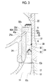
- a centrifugal compressor 10 according to a first embodiment of the present invention will be described.
- the centrifugal compressor 10 includes a rotary shaft 11 which is rotationally driven by a driving device such as a motor (not shown) or a turbine (not shown), an impeller 12 which is rotated around the rotary shaft 11, and a casing 20 which accommodates the rotary shaft 11 and the impeller 12 and forms a flow path for the fluid.
- a driving device such as a motor (not shown) or a turbine (not shown)
- an impeller 12 which is rotated around the rotary shaft 11
- a casing 20 which accommodates the rotary shaft 11 and the impeller 12 and forms a flow path for the fluid.
- the impeller 12 includes a hub 13 which is integrally provided with the rotary shaft 11 and a plurality of blades 14 which are provided on an outer peripheral surface of the hub 13.
- a curved surface 13c in which the outer diameter is gradually increased from an end part 13a of one end side of the rotary shaft 11 toward an end part 13b of the other end side is formed.
- the plurality of blades 14 are disposed on the curved surface 13c of the hub 13 in the circumferential direction.
- the blades 14 are configured of inner peripheral blades 14A provided on the inner peripheral side of the hub 13 and outer peripheral blades 14B provided on the outer peripheral side of the hub 13, and thus, may be a multiple configuration.
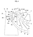
- the casing 20 includes a suction flow path 21 which is continuous along an axial direction of the rotary shaft 11 from a suction port 29 formed on one end 20a side toward the impeller 12, a diffuser part 30 which is annularly formed on the outer peripheral side of the impeller 12, a spiral volute part 22 which is continuously formed in the circumferential direction on the outer peripheral (downstream) side of the diffuser part 30 and in which a cross-sectional area in a cross-section orthogonal to the circumferential direction is gradually increased along the circumferential direction, and a discharge pipe 23 which is connected to a maximum area part 22b of the volute part 22 and extends in a tangential direction.
- a minimum area part 22a and the discharge pipe 23 are adjacent to the maximum area part 22b in the circumferential direction of the volute part 22.
- a tongue 28 is formed between the minimum area part 22a of the volute part 22 and the discharge pipe 23.
- the diffuser part 30 is opened to the inner peripheral side (impeller 12 side) and the outer peripheral side (volute part 22 side) over the entire circumference of the outer peripheral part of the impeller 12.
- the diffuser part 30 includes an annular disk part 31 which is formed on a part of the casing 20, an annular disk 32 which is disposed to oppose the annular disk part 31 at a set interval, and diffuser vanes 33 which are integrally formed with the annular disk 32 and provided at equal intervals in the circumferential direction of the annular disk 32.
- the diffuser vanes 33 are formed so as to be inclined in the radial direction of the annular disk 32. Accordingly, the interval between the diffuser vanes 33 and 33 adjacent to each other in the circumferential direction of the annular disk 32 is gradually increased from the inner peripheral side toward the outer peripheral side.
- the diffuser flow path 35 is formed between the annular disk part 31 and the annular disk 32.
- a diffuser member 34 which includes the annular disk 32 and the diffuser vanes 33 is separately formed with the casing 20, and the diffuser member is provided to be interposed between the annular disk part 31 which forms a part of the casing 20 and a holding part 24 of the casing 20 which is formed to oppose the annular disk part 31.
- an inner peripheral side end part 32a of the annular disk 32 is formed in a curved surface shape in which the interval between the inner peripheral side end part 32a and the annular disk part 31 is gradually decreased from an outer peripheral part 12a of the impeller 12 toward the outer periphery.
- annular disk 32 extends the outer peripheral side from the outer peripheral side end part 24a of the holding part 24 and is formed to protrude in the volute part 22.
- a connecting part 40A through which a side wall surface 32c facing the diffuser flow path 35 and a backface 32d opposite to the side wall surface 32c communicate with each other is formed on the outer peripheral side from the outer peripheral side end part 24a of the holding part 24.
- a plurality of the connecting parts 40A are formed at set intervals in the circumferential direction of the annular disk 32, and each of the connecting parts 40A is formed of a slit 41 which is continuous in the circumferential direction.
- the slits of the invention do not extend over the complete circumference. Instead, they are limited to a region from within 30° of an upstream side of the diffuser to within 30° of a downstream side thereof based on a tongue which is formed between a minimum area part of the volute and the discharge pipe.
- the connecting part 40A configured of the slit 41 or the like is formed so as to be inclined from the inner peripheral side of the diffuser part 30 to the outer peripheral side, from an opening end 40a of the backface 32d side toward an opening end (opening part) 40b of the side wall surface 32c side.
- the opening end 40b of the diffuser flow path 35 side is formed on the downstream side of the diffuser flow path 35. More preferably, the opening end 40b is formed in the outer peripheral side from a position which is positioned 75% from the center side of the diffuser part 30 with respect to the radius of the outer peripheral part of the diffuser part 30. In the inner peripheral side, since a static pressure difference between the opening end 40a and the opening end 40b is increased, a speed of the flow introduced from the connecting part 40A to the diffuser part 30 is increased, and thus, the flow inside the diffuser deteriorates.
- the centrifugal compressor 10 rotationally drives the impeller 12 around the rotary shaft 11 by the driving device such as the motor (not shown) or a turbine (not shown).
- the driving device such as the motor (not shown) or a turbine (not shown).
- Centrifugal force is applied to the fluid introduced into the casing 20 by the rotation of the blades 14 integrally rotated with the hub 13, and is compressed.
- the compressed fluid flows from the outer peripheral end of the impeller 12 into the diffuser part 30 of the outer peripheral side.
- airflow discharged from the impeller 12 to the outer peripheral side passes between the diffuser vanes 33 and 33 adjacent to the each other in the circumferential direction, and thus, the airflow is decelerated, and the static pressure is recovered.
- the fluid flowing in the volute part 22 of the outer periphery from the diffuser part 30 flows from the minimum area part 22a toward the maximum area part 22b, and is discharged from the discharge pipe 23 as a high-pressure compressed fluid.
- the high-pressure compressed fluid flowing in the volute part 22 through the diffuser part 30 is drawn into the diffuser flow path 35 between the annular disk part 31 and the annular disk 32 through the connecting part 40A.
- the diffuser part 30 according to the decreased flow rate, seperation occurs from the annular disk 32 in the diffuser flow path 35, and a reverse flow region H due to the seperation extends toward the rear edge (the edge part in the outer peripheral side) of the diffuser part 30.
- the diffuser member 34 including the annular disk 32 in which the connecting part 40A is formed and the diffuser vanes 33 may be separately formed with the casing 20. Accordingly, it is possible to easily process the connecting part 40A as a single body of the diffuser member 34.
- the plurality of slits 41 configuring the connecting part 40A is formed on only a part of the circumference.
- the slits 41 configuring the connecting part 40A may be formed only within a range from the tongue 28 to within 30° of the upstream side based on the tongue 28.
- the slits 41 configuring the connecting part 40A must be formed only in an area from within 30° of the upstream side to within 30° of the downstream side based on the tongue 28 in which the pressure distribution exists.
- the connecting part 40B is formed of through holes 42 instead of slits 41, and the connecting part 40B including the through holes 42 is formed so as to be parallel with the outer peripheral side end part 33b of the diffuser vane 33 and to be inclined approximately at the angle in the radial direction of the annular disk 32, from the opening end 40a of the backface 32d side of the annular disk 32 toward the opening end 40b of the side wall surface 32c side.
- the high-pressure compressed fluid flowing into the diffuser flow path 35 from the opening end 40b through the connecting part 40B can suppress turbulence in the flow between the diffuser vanes 33 and 33 adjacent in the circumferential direction. Therefore, it is possible to more certainly prevent occurrence of the surging in the diffuser part 30, and it is possible to further increase the operational range of the centrifugal compressor 10.
- the connecting part 40B may be formed in only the range up to within 30° of the upstream side with respect to the tongue 28.
- the cross-sectional shapes, sizes, dispositions, or the like of the connecting parts 40A and 40B are not limited.
- a plurality of rows (a plurality of plies) of the connecting parts 40A and 40B may be disposed on the inner peripheral side and the outer peripheral side.
- the diffuser vanes 33 may be removed, and the casing 20 and the holding part 24 may be an integral structure.
Applications Claiming Priority (2)
| Application Number | Priority Date | Filing Date | Title |
|---|---|---|---|
| JP2012268402A JP6138470B2 (ja) | 2012-12-07 | 2012-12-07 | 遠心圧縮機 |
| PCT/JP2013/067359 WO2014087690A1 (ja) | 2012-12-07 | 2013-06-25 | 遠心圧縮機 |
Publications (3)
| Publication Number | Publication Date |
|---|---|
| EP2886875A1 EP2886875A1 (en) | 2015-06-24 |
| EP2886875A4 EP2886875A4 (en) | 2015-10-07 |
| EP2886875B1 true EP2886875B1 (en) | 2016-08-03 |
Family
ID=50883124
Family Applications (1)
| Application Number | Title | Priority Date | Filing Date |
|---|---|---|---|
| EP13859857.8A Not-in-force EP2886875B1 (en) | 2012-12-07 | 2013-06-25 | Centrifugal compressor |
Country Status (5)
| Country | Link |
|---|---|
| EP (1) | EP2886875B1 (ja) |
| JP (1) | JP6138470B2 (ja) |
| KR (1) | KR101743376B1 (ja) |
| CN (1) | CN104838149B (ja) |
| WO (1) | WO2014087690A1 (ja) |
Families Citing this family (10)
| Publication number | Priority date | Publication date | Assignee | Title |
|---|---|---|---|---|
| KR102511426B1 (ko) * | 2014-12-23 | 2023-03-17 | 터보 시스템즈 스위츠랜드 엘티디. | 레이디얼 압축기용의 디퓨저 |
| CN106438487A (zh) * | 2016-11-21 | 2017-02-22 | 南京磁谷科技有限公司 | 一种可调节型蜗壳 |
| JP6704843B2 (ja) * | 2016-12-07 | 2020-06-03 | 三菱重工エンジン&ターボチャージャ株式会社 | 遠心圧縮機及びターボチャージャ |
| DE102017101590A1 (de) * | 2017-01-27 | 2018-08-02 | Man Diesel & Turbo Se | Radialverdichter und Turbolader |
| KR102545555B1 (ko) * | 2018-06-12 | 2023-06-20 | 엘지전자 주식회사 | 원심 압축기 |
| KR102545557B1 (ko) * | 2018-06-12 | 2023-06-21 | 엘지전자 주식회사 | 원심 압축기 |
| CN111219361B (zh) * | 2018-07-17 | 2021-05-11 | 浙江颐顿机电有限公司 | 一种用于压缩机或鼓风机的叶轮结构 |
| JP7299182B2 (ja) * | 2020-02-28 | 2023-06-27 | 日立グローバルライフソリューションズ株式会社 | 送風機および洗濯機 |
| JP7468203B2 (ja) | 2020-07-07 | 2024-04-16 | 三菱電機ビルソリューションズ株式会社 | 空調システムの点検器具 |
| KR102420181B1 (ko) * | 2022-02-18 | 2022-07-11 | 정성래 | 무냉매 냉방장치용 냉각터빈장치 |
Family Cites Families (9)
| Publication number | Priority date | Publication date | Assignee | Title |
|---|---|---|---|---|
| US2399072A (en) * | 1944-10-18 | 1946-04-23 | Gen Electric | Centrifugal compressor |
| DE1428102B2 (de) * | 1962-09-12 | 1971-06-03 | Geratebau Eberspacher KG, 7300 Ess hngen | Vorrichtung zum anfachen der grenzschicht bei einem radial verdichter |
| JPS60132099A (ja) * | 1983-12-19 | 1985-07-13 | Hitachi Ltd | 遠心圧縮機 |
| DE4125487C1 (en) * | 1991-08-01 | 1992-06-17 | Mtu Friedrichshafen Gmbh | Flow casing for radial-flow compressor - has side duct in restricted peripheral section in narrow region of spiral cross=section |
| JPH05263796A (ja) * | 1992-03-18 | 1993-10-12 | Daikin Ind Ltd | ターボ圧縮機 |
| JP2003013895A (ja) * | 2001-06-27 | 2003-01-15 | Mitsubishi Heavy Ind Ltd | 遠心圧縮機 |
| JP2005240680A (ja) | 2004-02-26 | 2005-09-08 | Mitsubishi Heavy Ind Ltd | 遠心圧縮機 |
| JP2007211717A (ja) * | 2006-02-10 | 2007-08-23 | Toyota Motor Corp | 遠心圧縮機 |
| JP2010151034A (ja) | 2008-12-25 | 2010-07-08 | Ihi Corp | 遠心圧縮機 |
-
2012
- 2012-12-07 JP JP2012268402A patent/JP6138470B2/ja active Active
-
2013
- 2013-06-25 KR KR1020157006939A patent/KR101743376B1/ko active IP Right Grant
- 2013-06-25 WO PCT/JP2013/067359 patent/WO2014087690A1/ja active Application Filing
- 2013-06-25 CN CN201380050088.1A patent/CN104838149B/zh active Active
- 2013-06-25 EP EP13859857.8A patent/EP2886875B1/en not_active Not-in-force
Also Published As
| Publication number | Publication date |
|---|---|
| EP2886875A4 (en) | 2015-10-07 |
| WO2014087690A1 (ja) | 2014-06-12 |
| EP2886875A1 (en) | 2015-06-24 |
| JP2014114727A (ja) | 2014-06-26 |
| JP6138470B2 (ja) | 2017-05-31 |
| CN104838149A (zh) | 2015-08-12 |
| KR101743376B1 (ko) | 2017-06-02 |
| KR20150046181A (ko) | 2015-04-29 |
| CN104838149B (zh) | 2017-04-19 |
Similar Documents
| Publication | Publication Date | Title |
|---|---|---|
| EP2886875B1 (en) | Centrifugal compressor | |
| US8568095B2 (en) | Reduced tip clearance losses in axial flow fans | |
| JP6323454B2 (ja) | 遠心圧縮機及び過給機 | |
| US9885368B2 (en) | Stall margin enhancement of axial fan with rotating shroud | |
| CN107532612B (zh) | 离心式鼓风机 | |
| WO2018181343A1 (ja) | 遠心圧縮機 | |
| JP2008175124A (ja) | 遠心圧縮機 | |
| JP2008151022A (ja) | 軸流圧縮機の翼列 | |
| US10138898B2 (en) | Centrifugal compressor and turbocharger | |
| US20150354588A1 (en) | Centrifugal compressor | |
| EP3567260B1 (en) | Centrifugal rotary machine | |
| EP3561312B1 (en) | Centrifugal compressor | |
| WO2008082397A1 (en) | Reduced tip clearance losses in axial flow fans | |
| JP5980671B2 (ja) | 回転機械 | |
| JP2013002280A (ja) | 遠心圧縮機 | |
| WO2018074591A1 (ja) | インペラ及び回転機械 | |
| US11187242B2 (en) | Multi-stage centrifugal compressor | |
| US20220186746A1 (en) | Centrifugal or mixed-flow compressor including aspirated diffuser | |
| JP2013053532A (ja) | 軸流送風機及び空気調和機 | |
| JP4146371B2 (ja) | 遠心圧縮機 | |
| JP6265000B2 (ja) | 遠心圧縮機 | |
| KR102223293B1 (ko) | 회전 기계, 회전 기계의 배기 부재 | |
| EP3686439B1 (en) | Multi-stage centrifugal compressor | |
| JP6215154B2 (ja) | 回転機械 | |
| JP6700893B2 (ja) | 羽根車、回転機械 |
Legal Events
| Date | Code | Title | Description |
|---|---|---|---|
| PUAI | Public reference made under article 153(3) epc to a published international application that has entered the european phase |
Free format text: ORIGINAL CODE: 0009012 |
|
| 17P | Request for examination filed |
Effective date: 20150317 |
|
| AK | Designated contracting states |
Kind code of ref document: A1 Designated state(s): AL AT BE BG CH CY CZ DE DK EE ES FI FR GB GR HR HU IE IS IT LI LT LU LV MC MK MT NL NO PL PT RO RS SE SI SK SM TR |
|
| AX | Request for extension of the european patent |
Extension state: BA ME |
|
| RA4 | Supplementary search report drawn up and despatched (corrected) |
Effective date: 20150909 |
|
| RIC1 | Information provided on ipc code assigned before grant |
Ipc: F04D 29/42 20060101AFI20150903BHEP Ipc: F04D 29/66 20060101ALI20150903BHEP Ipc: F04D 29/44 20060101ALI20150903BHEP |
|
| DAX | Request for extension of the european patent (deleted) | ||
| GRAP | Despatch of communication of intention to grant a patent |
Free format text: ORIGINAL CODE: EPIDOSNIGR1 |
|
| INTG | Intention to grant announced |
Effective date: 20160321 |
|
| GRAS | Grant fee paid |
Free format text: ORIGINAL CODE: EPIDOSNIGR3 |
|
| GRAA | (expected) grant |
Free format text: ORIGINAL CODE: 0009210 |
|
| AK | Designated contracting states |
Kind code of ref document: B1 Designated state(s): AL AT BE BG CH CY CZ DE DK EE ES FI FR GB GR HR HU IE IS IT LI LT LU LV MC MK MT NL NO PL PT RO RS SE SI SK SM TR |
|
| REG | Reference to a national code |
Ref country code: GB Ref legal event code: FG4D |
|
| REG | Reference to a national code |
Ref country code: CH Ref legal event code: EP Ref country code: AT Ref legal event code: REF Ref document number: 817526 Country of ref document: AT Kind code of ref document: T Effective date: 20160815 |
|
| REG | Reference to a national code |
Ref country code: IE Ref legal event code: FG4D |
|
| REG | Reference to a national code |
Ref country code: DE Ref legal event code: R096 Ref document number: 602013010156 Country of ref document: DE |
|
| REG | Reference to a national code |
Ref country code: NL Ref legal event code: MP Effective date: 20160803 |
|
| REG | Reference to a national code |
Ref country code: LT Ref legal event code: MG4D |
|
| REG | Reference to a national code |
Ref country code: AT Ref legal event code: MK05 Ref document number: 817526 Country of ref document: AT Kind code of ref document: T Effective date: 20160803 |
|
| PG25 | Lapsed in a contracting state [announced via postgrant information from national office to epo] |
Ref country code: IT Free format text: LAPSE BECAUSE OF FAILURE TO SUBMIT A TRANSLATION OF THE DESCRIPTION OR TO PAY THE FEE WITHIN THE PRESCRIBED TIME-LIMIT Effective date: 20160803 Ref country code: RS Free format text: LAPSE BECAUSE OF FAILURE TO SUBMIT A TRANSLATION OF THE DESCRIPTION OR TO PAY THE FEE WITHIN THE PRESCRIBED TIME-LIMIT Effective date: 20160803 Ref country code: FI Free format text: LAPSE BECAUSE OF FAILURE TO SUBMIT A TRANSLATION OF THE DESCRIPTION OR TO PAY THE FEE WITHIN THE PRESCRIBED TIME-LIMIT Effective date: 20160803 Ref country code: NO Free format text: LAPSE BECAUSE OF FAILURE TO SUBMIT A TRANSLATION OF THE DESCRIPTION OR TO PAY THE FEE WITHIN THE PRESCRIBED TIME-LIMIT Effective date: 20161103 Ref country code: IS Free format text: LAPSE BECAUSE OF FAILURE TO SUBMIT A TRANSLATION OF THE DESCRIPTION OR TO PAY THE FEE WITHIN THE PRESCRIBED TIME-LIMIT Effective date: 20161203 Ref country code: LT Free format text: LAPSE BECAUSE OF FAILURE TO SUBMIT A TRANSLATION OF THE DESCRIPTION OR TO PAY THE FEE WITHIN THE PRESCRIBED TIME-LIMIT Effective date: 20160803 Ref country code: HR Free format text: LAPSE BECAUSE OF FAILURE TO SUBMIT A TRANSLATION OF THE DESCRIPTION OR TO PAY THE FEE WITHIN THE PRESCRIBED TIME-LIMIT Effective date: 20160803 Ref country code: NL Free format text: LAPSE BECAUSE OF FAILURE TO SUBMIT A TRANSLATION OF THE DESCRIPTION OR TO PAY THE FEE WITHIN THE PRESCRIBED TIME-LIMIT Effective date: 20160803 |
|
| PG25 | Lapsed in a contracting state [announced via postgrant information from national office to epo] |
Ref country code: SE Free format text: LAPSE BECAUSE OF FAILURE TO SUBMIT A TRANSLATION OF THE DESCRIPTION OR TO PAY THE FEE WITHIN THE PRESCRIBED TIME-LIMIT Effective date: 20160803 Ref country code: GR Free format text: LAPSE BECAUSE OF FAILURE TO SUBMIT A TRANSLATION OF THE DESCRIPTION OR TO PAY THE FEE WITHIN THE PRESCRIBED TIME-LIMIT Effective date: 20161104 Ref country code: ES Free format text: LAPSE BECAUSE OF FAILURE TO SUBMIT A TRANSLATION OF THE DESCRIPTION OR TO PAY THE FEE WITHIN THE PRESCRIBED TIME-LIMIT Effective date: 20160803 Ref country code: LV Free format text: LAPSE BECAUSE OF FAILURE TO SUBMIT A TRANSLATION OF THE DESCRIPTION OR TO PAY THE FEE WITHIN THE PRESCRIBED TIME-LIMIT Effective date: 20160803 Ref country code: PL Free format text: LAPSE BECAUSE OF FAILURE TO SUBMIT A TRANSLATION OF THE DESCRIPTION OR TO PAY THE FEE WITHIN THE PRESCRIBED TIME-LIMIT Effective date: 20160803 Ref country code: AT Free format text: LAPSE BECAUSE OF FAILURE TO SUBMIT A TRANSLATION OF THE DESCRIPTION OR TO PAY THE FEE WITHIN THE PRESCRIBED TIME-LIMIT Effective date: 20160803 Ref country code: PT Free format text: LAPSE BECAUSE OF FAILURE TO SUBMIT A TRANSLATION OF THE DESCRIPTION OR TO PAY THE FEE WITHIN THE PRESCRIBED TIME-LIMIT Effective date: 20161205 |
|
| PG25 | Lapsed in a contracting state [announced via postgrant information from national office to epo] |
Ref country code: RO Free format text: LAPSE BECAUSE OF FAILURE TO SUBMIT A TRANSLATION OF THE DESCRIPTION OR TO PAY THE FEE WITHIN THE PRESCRIBED TIME-LIMIT Effective date: 20160803 Ref country code: EE Free format text: LAPSE BECAUSE OF FAILURE TO SUBMIT A TRANSLATION OF THE DESCRIPTION OR TO PAY THE FEE WITHIN THE PRESCRIBED TIME-LIMIT Effective date: 20160803 |
|
| REG | Reference to a national code |
Ref country code: DE Ref legal event code: R097 Ref document number: 602013010156 Country of ref document: DE |
|
| PG25 | Lapsed in a contracting state [announced via postgrant information from national office to epo] |
Ref country code: BG Free format text: LAPSE BECAUSE OF FAILURE TO SUBMIT A TRANSLATION OF THE DESCRIPTION OR TO PAY THE FEE WITHIN THE PRESCRIBED TIME-LIMIT Effective date: 20161103 Ref country code: SM Free format text: LAPSE BECAUSE OF FAILURE TO SUBMIT A TRANSLATION OF THE DESCRIPTION OR TO PAY THE FEE WITHIN THE PRESCRIBED TIME-LIMIT Effective date: 20160803 Ref country code: SK Free format text: LAPSE BECAUSE OF FAILURE TO SUBMIT A TRANSLATION OF THE DESCRIPTION OR TO PAY THE FEE WITHIN THE PRESCRIBED TIME-LIMIT Effective date: 20160803 Ref country code: DK Free format text: LAPSE BECAUSE OF FAILURE TO SUBMIT A TRANSLATION OF THE DESCRIPTION OR TO PAY THE FEE WITHIN THE PRESCRIBED TIME-LIMIT Effective date: 20160803 Ref country code: BE Free format text: LAPSE BECAUSE OF FAILURE TO SUBMIT A TRANSLATION OF THE DESCRIPTION OR TO PAY THE FEE WITHIN THE PRESCRIBED TIME-LIMIT Effective date: 20160803 Ref country code: CZ Free format text: LAPSE BECAUSE OF FAILURE TO SUBMIT A TRANSLATION OF THE DESCRIPTION OR TO PAY THE FEE WITHIN THE PRESCRIBED TIME-LIMIT Effective date: 20160803 |
|
| PLBE | No opposition filed within time limit |
Free format text: ORIGINAL CODE: 0009261 |
|
| STAA | Information on the status of an ep patent application or granted ep patent |
Free format text: STATUS: NO OPPOSITION FILED WITHIN TIME LIMIT |
|
| 26N | No opposition filed |
Effective date: 20170504 |
|
| PG25 | Lapsed in a contracting state [announced via postgrant information from national office to epo] |
Ref country code: SI Free format text: LAPSE BECAUSE OF FAILURE TO SUBMIT A TRANSLATION OF THE DESCRIPTION OR TO PAY THE FEE WITHIN THE PRESCRIBED TIME-LIMIT Effective date: 20160803 |
|
| REG | Reference to a national code |
Ref country code: DE Ref legal event code: R119 Ref document number: 602013010156 Country of ref document: DE |
|
| PG25 | Lapsed in a contracting state [announced via postgrant information from national office to epo] |
Ref country code: MC Free format text: LAPSE BECAUSE OF FAILURE TO SUBMIT A TRANSLATION OF THE DESCRIPTION OR TO PAY THE FEE WITHIN THE PRESCRIBED TIME-LIMIT Effective date: 20160803 |
|
| REG | Reference to a national code |
Ref country code: CH Ref legal event code: PL |
|
| GBPC | Gb: european patent ceased through non-payment of renewal fee |
Effective date: 20170625 |
|
| REG | Reference to a national code |
Ref country code: IE Ref legal event code: MM4A |
|
| REG | Reference to a national code |
Ref country code: FR Ref legal event code: ST Effective date: 20180228 |
|
| PG25 | Lapsed in a contracting state [announced via postgrant information from national office to epo] |
Ref country code: DE Free format text: LAPSE BECAUSE OF NON-PAYMENT OF DUE FEES Effective date: 20180103 Ref country code: LU Free format text: LAPSE BECAUSE OF NON-PAYMENT OF DUE FEES Effective date: 20170625 Ref country code: CH Free format text: LAPSE BECAUSE OF NON-PAYMENT OF DUE FEES Effective date: 20170630 Ref country code: GB Free format text: LAPSE BECAUSE OF NON-PAYMENT OF DUE FEES Effective date: 20170625 Ref country code: LI Free format text: LAPSE BECAUSE OF NON-PAYMENT OF DUE FEES Effective date: 20170630 Ref country code: IE Free format text: LAPSE BECAUSE OF NON-PAYMENT OF DUE FEES Effective date: 20170625 |
|
| PG25 | Lapsed in a contracting state [announced via postgrant information from national office to epo] |
Ref country code: FR Free format text: LAPSE BECAUSE OF NON-PAYMENT OF DUE FEES Effective date: 20170630 |
|
| PG25 | Lapsed in a contracting state [announced via postgrant information from national office to epo] |
Ref country code: MT Free format text: LAPSE BECAUSE OF NON-PAYMENT OF DUE FEES Effective date: 20170625 |
|
| PG25 | Lapsed in a contracting state [announced via postgrant information from national office to epo] |
Ref country code: AL Free format text: LAPSE BECAUSE OF FAILURE TO SUBMIT A TRANSLATION OF THE DESCRIPTION OR TO PAY THE FEE WITHIN THE PRESCRIBED TIME-LIMIT Effective date: 20160803 |
|
| PG25 | Lapsed in a contracting state [announced via postgrant information from national office to epo] |
Ref country code: HU Free format text: LAPSE BECAUSE OF FAILURE TO SUBMIT A TRANSLATION OF THE DESCRIPTION OR TO PAY THE FEE WITHIN THE PRESCRIBED TIME-LIMIT; INVALID AB INITIO Effective date: 20130625 |
|
| PG25 | Lapsed in a contracting state [announced via postgrant information from national office to epo] |
Ref country code: CY Free format text: LAPSE BECAUSE OF FAILURE TO SUBMIT A TRANSLATION OF THE DESCRIPTION OR TO PAY THE FEE WITHIN THE PRESCRIBED TIME-LIMIT Effective date: 20160803 |
|
| PG25 | Lapsed in a contracting state [announced via postgrant information from national office to epo] |
Ref country code: MK Free format text: LAPSE BECAUSE OF FAILURE TO SUBMIT A TRANSLATION OF THE DESCRIPTION OR TO PAY THE FEE WITHIN THE PRESCRIBED TIME-LIMIT Effective date: 20160803 |
|
| PG25 | Lapsed in a contracting state [announced via postgrant information from national office to epo] |
Ref country code: TR Free format text: LAPSE BECAUSE OF FAILURE TO SUBMIT A TRANSLATION OF THE DESCRIPTION OR TO PAY THE FEE WITHIN THE PRESCRIBED TIME-LIMIT Effective date: 20160803 |