EP2886770B2 - Vorrichtung zur Regelung der Schließfolge einer zweiflügeligen Tür - Google Patents
Vorrichtung zur Regelung der Schließfolge einer zweiflügeligen Tür Download PDFInfo
- Publication number
- EP2886770B2 EP2886770B2 EP14193612.0A EP14193612A EP2886770B2 EP 2886770 B2 EP2886770 B2 EP 2886770B2 EP 14193612 A EP14193612 A EP 14193612A EP 2886770 B2 EP2886770 B2 EP 2886770B2
- Authority
- EP
- European Patent Office
- Prior art keywords
- lever
- leaf
- valve
- arm
- active
- Prior art date
- Legal status (The legal status is an assumption and is not a legal conclusion. Google has not performed a legal analysis and makes no representation as to the accuracy of the status listed.)
- Active
Links
Images

Classifications
-
- E—FIXED CONSTRUCTIONS
- E05—LOCKS; KEYS; WINDOW OR DOOR FITTINGS; SAFES
- E05F—DEVICES FOR MOVING WINGS INTO OPEN OR CLOSED POSITION; CHECKS FOR WINGS; WING FITTINGS NOT OTHERWISE PROVIDED FOR, CONCERNED WITH THE FUNCTIONING OF THE WING
- E05F5/00—Braking devices, e.g. checks; Stops; Buffers
- E05F5/12—Braking devices, e.g. checks; Stops; Buffers specially for preventing the closing of a wing before another wing has been closed
-
- E—FIXED CONSTRUCTIONS
- E05—LOCKS; KEYS; WINDOW OR DOOR FITTINGS; SAFES
- E05F—DEVICES FOR MOVING WINGS INTO OPEN OR CLOSED POSITION; CHECKS FOR WINGS; WING FITTINGS NOT OTHERWISE PROVIDED FOR, CONCERNED WITH THE FUNCTIONING OF THE WING
- E05F3/00—Closers or openers with braking devices, e.g. checks; Construction of pneumatic or liquid braking devices
- E05F3/04—Closers or openers with braking devices, e.g. checks; Construction of pneumatic or liquid braking devices with liquid piston brakes
- E05F3/12—Special devices controlling the circulation of the liquid, e.g. valve arrangement
-
- E—FIXED CONSTRUCTIONS
- E05—LOCKS; KEYS; WINDOW OR DOOR FITTINGS; SAFES
- E05F—DEVICES FOR MOVING WINGS INTO OPEN OR CLOSED POSITION; CHECKS FOR WINGS; WING FITTINGS NOT OTHERWISE PROVIDED FOR, CONCERNED WITH THE FUNCTIONING OF THE WING
- E05F3/00—Closers or openers with braking devices, e.g. checks; Construction of pneumatic or liquid braking devices
- E05F3/22—Additional arrangements for closers, e.g. for holding the wing in opened or other position
- E05F3/223—Hydraulic power-locks, e.g. with electrically operated hydraulic valves
-
- E—FIXED CONSTRUCTIONS
- E05—LOCKS; KEYS; WINDOW OR DOOR FITTINGS; SAFES
- E05Y—INDEXING SCHEME ASSOCIATED WITH SUBCLASSES E05D AND E05F, RELATING TO CONSTRUCTION ELEMENTS, ELECTRIC CONTROL, POWER SUPPLY, POWER SIGNAL OR TRANSMISSION, USER INTERFACES, MOUNTING OR COUPLING, DETAILS, ACCESSORIES, AUXILIARY OPERATIONS NOT OTHERWISE PROVIDED FOR, APPLICATION THEREOF
- E05Y2201/00—Constructional elements; Accessories therefor
- E05Y2201/60—Suspension or transmission members; Accessories therefor
- E05Y2201/622—Suspension or transmission members elements
- E05Y2201/624—Arms
- E05Y2201/626—Levers
-
- E—FIXED CONSTRUCTIONS
- E05—LOCKS; KEYS; WINDOW OR DOOR FITTINGS; SAFES
- E05Y—INDEXING SCHEME ASSOCIATED WITH SUBCLASSES E05D AND E05F, RELATING TO CONSTRUCTION ELEMENTS, ELECTRIC CONTROL, POWER SUPPLY, POWER SIGNAL OR TRANSMISSION, USER INTERFACES, MOUNTING OR COUPLING, DETAILS, ACCESSORIES, AUXILIARY OPERATIONS NOT OTHERWISE PROVIDED FOR, APPLICATION THEREOF
- E05Y2201/00—Constructional elements; Accessories therefor
- E05Y2201/60—Suspension or transmission members; Accessories therefor
- E05Y2201/622—Suspension or transmission members elements
- E05Y2201/644—Flexible elongated pulling elements
- E05Y2201/654—Cables
-
- E—FIXED CONSTRUCTIONS
- E05—LOCKS; KEYS; WINDOW OR DOOR FITTINGS; SAFES
- E05Y—INDEXING SCHEME ASSOCIATED WITH SUBCLASSES E05D AND E05F, RELATING TO CONSTRUCTION ELEMENTS, ELECTRIC CONTROL, POWER SUPPLY, POWER SIGNAL OR TRANSMISSION, USER INTERFACES, MOUNTING OR COUPLING, DETAILS, ACCESSORIES, AUXILIARY OPERATIONS NOT OTHERWISE PROVIDED FOR, APPLICATION THEREOF
- E05Y2201/00—Constructional elements; Accessories therefor
- E05Y2201/60—Suspension or transmission members; Accessories therefor
- E05Y2201/622—Suspension or transmission members elements
- E05Y2201/658—Members cooperating with flexible elongated pulling elements
- E05Y2201/66—Deflectors; Guides
- E05Y2201/662—Cable sheaths
Definitions
- the present invention relates to a device for regulating the closing sequence of a two-leaf door having a fixed leaf and an active leaf with a hydraulic drive in order to drive the active leaf in the closing and, in particular, the opening direction.
- the device comprises a control arrangement which can be actuated via the inactive leaf and interacts with the hydraulic drive.
- the control arrangement comprises an actuator, which is arranged in the area of the stationary leaf on the pivot axis side and can be moved through the stationary leaf between a first and a second switching position, and a connecting element connected to the actuator, extending to a trigger arrangement on the active leaf side and mechanically transmitting the actuator movement.
- the trigger arrangement has a valve that controls the hydraulic drive.
- Devices of this type are known. They must ensure that the two leaves of a double-leaf door are always moved into the closed position from any open position in such a way that the passive leaf is the first to enter the closed position and then the active leaf enters the closed position so that the door is properly and completely closed.
- a device for closing sequence control of the type mentioned is from the publications DE 32 21 534 A1 which discloses an apparatus according to the preamble of claim 1, DE 33 29 543 A1 and EP 0 141 902 B1 known.
- an actuator interacting with an inactive leaf actuates a Bowden cable which controls a valve arranged on an active leaf.
- the valve is opened via the Bowden cable, the hydraulic fluid can flow out of the closing piston and thus ensure that the passive leaf is always closed before the active leaf.
- the invention is based on the object of creating a device of the type mentioned at the outset, which can be manufactured and easily assembled in a particularly inexpensive yet operationally reliable manner.
- the trigger arrangement comprising the lever and the valve forms a self-contained assembly that can be manufactured inexpensively and can be used in the device for regulating the closing sequence together with components that are already available, such as a conventional control arrangement.
- the valve has a valve body from which a pin protrudes, which a spring presses against the lever.
- the lever preferably interacts with the pin in such a way that the pin is engaged or disengaged depending on the switching position of the actuator.
- the position of the pin determines whether the valve is open or closed.
- the lever can thus transmit the actuator movement to the valve in a simple manner.
- a roller bearing arranged on the lever can be provided against which the pin is pressed.
- the roller bearing prevents transverse forces acting on the pin and leading to wear.
- the lever is biased into the blocking position by means of a compression spring.
- the spring force exerted on the lever by the compression spring can advantageously be adjustable.
- the compression spring can be compressed or relaxed for this purpose by adding or removing washers.
- the valve is preferably designed in such a way that it blocks or allows the closing movement of the active leaf as a function of its open state.
- the valve is connected to the hydraulic drive via a hydraulic connecting line. This makes it possible to block or allow the closing movement of the active leaf in that the valve blocks or allows the flow of hydraulic fluid through the connecting line as a function of its open state.
- the connecting element which mechanically transmits the actuator movement comprises a Bowden cable and the actuator preferably comprises an eccentric.
- a further preferred embodiment provides that the end of the connecting member on the active leaf side engages a first lever arm of the lever extending from the axis of rotation in a first direction and a second lever arm of the lever extending from the axis of rotation in a second direction interacts with the valve.
- the trigger arrangement advantageously has a holder with a first and a second arm, the lever being rotatably fastened to the first arm of the holder and the compression spring being fastened to the second arm of the holder.
- the second arm is oriented at right angles to the first arm.
- the compression spring preferably presses against the second lever arm and thereby biases the lever into the blocking position.
- the release arrangement forms a self-contained assembly, it can advantageously be preassembled and then flanged to the hydraulic drive of the active leaf.
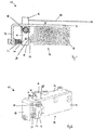
- Fig. 1 shows a schematic representation of a release arrangement 10 on the active leaf side of a device for regulating the closing sequence of a two-leaf door having a fixed leaf and an active leaf.
- the trigger arrangement 10 comprises a holder 11 with a first arm 12 and a second arm 13 which is oriented essentially at right angles to the first arm 12.
- the trigger arrangement 10 also has a lever 14 which is fastened to the first arm 12 of the holder 11 and which is mounted rotatably about an axis of rotation 15.
- the axis of rotation 15 runs perpendicular to the plane of the drawing.
- the lever 14 consists of a first lever arm 16 and a second lever arm 17 which, starting from the axis of rotation 15, extend in opposite directions.
- a valve 18 with its valve body 19 is also attached to the first arm 12 of the holder 11. From the valve body 19 protrudes a valve pin 20, which is arranged within the valve body 19 and therefore in Fig. 1
- the spring not shown, is biased in the direction of the second lever arm 17.
- a roller bearing 21 is rotatably mounted on the second lever arm 17 about an axis of rotation 22 running perpendicular to the plane of the drawing, against which the valve pin 20 is pressed by the spring.
- a compression spring 23 exerts a preload on the second lever arm 17.
- the compression spring 23 is attached to the second arm 13 of the holder 11.
- the compression spring 23 presses the second lever arm 17 against the valve pin 20.
- the force exerted by the compression spring 23 on the lever arm 17 can be adjusted by the Adding or removing washers, the compression spring 23 is compressed or relaxed.
- a connecting element which is designed as a Bowden cable 24, on the active leaf side engages the first lever arm 16.
- the Bowden cable 24 is attached to the first lever arm 16 in such a way that a pull on the Bowden cable 24 causes the second lever arm 17 to be deflected away from the valve pin 20 and thus in the direction of the compression spring 22.
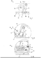
- Fig. 2 the trigger arrangement 10 is shown in a perspective view, the Bowden cable 24 in FIG Fig. 2 is not shown. However, in Fig. 2 a recess 25 is shown in the first arm 11 of the holder 12, through which the lever 14 is guided. Also shows Fig. 2 a recess 26 in the lever 14, which is used to attach the Bowden cable 14.
- Fig. 3 shows a schematic representation of a control arrangement 30 on the stationary leaf.
- the control arrangement 30 comprises a cam disk 31 with a control contour 32, which is mounted on a rotary spindle 33 of the hydraulic drive of the stationary leaf.
- control arrangement 30 comprises a lever 34 which is rotatably fastened at one end to the hydraulic drive of the passive leaf and at the other end of which the Bowden cable 24 is fastened.
- a fastening element 35 is provided which is rotatably mounted on the lever 34 and which has an opening for receiving a wire cable 36 of the Bowden cable 24.
- the wire rope 36 is held on the fastening element 35 by means of a clamping screw 37.
- the rotating spindle 33 is designed as a drive element and is coupled to the inactive leaf by means of a swivel arm 39.
- the rotating spindle 33 rotates about its axis of rotation when the inactive leaf moves between an open position and a closed position.
- the lever 34 is correspondingly deflected and a tensile force is exerted on the Bowden cable 24.
- the lever 34 can accordingly assume two positions, a first switching position in the non-deflected state and a second switching position in the deflected state.
- the Bowden cable 24 transmits the movement of the lever 34 to the trigger arrangement 10 on the active leaf side.
- Hydraulic connecting lines are connected to the valve 18, the other ends of which are connected to the hydraulic circuit of the drive on the active leaf side, which is used to drive the active leaf in the opening and closing directions.
- the construction of the valve 18 in the present embodiment is selected such that the valve 18 is open when the valve pin 20 is disengaged from the valve housing 19. In this position, a flow of hydraulic fluid through the hydraulic drive of the active leaf is not prevented, with the result that the active leaf can be moved freely.
- valve 18 When the valve pin 20 is engaged in the valve housing 19, the valve 18 is closed. As a result, hydraulic fluid can no longer flow through the hydraulic drive of the active leaf and the active leaf can therefore no longer be moved.
- FIGS 4A and 4B show the control assembly 30 and the trigger assembly 10 during assembly.
- the trigger arrangement 10 forms a self-contained assembly and can therefore be preassembled and then flanged to the hydraulic drive of the active leaf.
- FIGS 5A and 5B show the control arrangement 30 and the release arrangement 10 with the stationary and active leaves closed.
- the cam disk 31 is adjusted in such a way that, when the stationary leaf is closed, the lever 34 on the stationary leaf side is actuated by the control contour 32 of the cam disk 31.
- the Bowden cable 24 transmits the position of the lever 34 to the lever 14 of the trigger arrangement 10, which causes the valve pin 20 to be disengaged from the valve housing 19 and the valve 18 to be opened as a result.
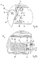
- FIGS 6A and 6B show the control arrangement 30 and the release arrangement 10 with the fixed and active leaves open.
- the control contour 32 of the cam disk 31 is not in contact with the roller bearing 38 of the lever 34 and the Bowden cable 24 is therefore relieved.
- the valve pin 20 of the release arrangement is pushed into the valve housing 19 by the pretensioning force of the compression spring 23, with the result that the valve 18 is closed.
- the hydraulic drives of the passive and active leaves work together with the device for regulating the closing sequence comprising the control arrangement 30 and the release arrangement 10 as follows: If both doors, ie the inactive leaf and the active leaf, are opened, these two doors run if they are not detected to go back to normal.
- the active leaf is blocked only at an angle defined by the cam disk 31 or the control contour 32 of the cam disk 31, since the control contour 32 deflects the lever 34 and thereby the valve 18 is closed, whereby the further closing movement of the active leaf is blocked.
- the holding angle of the active leaf defined by the position of the control contour 32 on the cam disk 31 must be selected so that the passive leaf can pass the active leaf when the active leaf is blocked. This is possible, for example, with an opening angle of the active leaf in the range from 20 ° to 40 ° and the angle determined by the position of the control contour 32 on the cam disk 31 is selected in this range.
Landscapes
- Power-Operated Mechanisms For Wings (AREA)
Description
- Die vorliegende Erfindung betrifft eine Vorrichtung zur Regelung der Schließfolge einer zweiflügeligen, einen Standflügel und einen Gangflügel aufweisenden Tür mit einem hydraulischen Antrieb, um den Gangflügel in Schließ- und insbesondere Öffnungsrichtung anzutreiben. Die Vorrichtung umfasst eine über den Standflügel betätigbare, mit dem hydraulischen Antrieb zusammenwirkende Steueranordnung. Die Steueranordnung umfasst ein im schwenkachsenseitigen Bereich des Standflügels angeordnetes, durch den Standflügel zwischen einer ersten und einer zweiten Schaltstellung bewegbares Stellglied und ein mit dem Stellglied verbundenes, sich bis zu einer gangflügelseitigen Auslöseanordnung erstreckendes und die Stellgliedbewegung mechanisch übertragendes Verbindungsorgan. Die Auslöseanordnung weist ein den hydraulischen Antrieb steuerndes Ventil auf.
- Vorrichtungen dieser Art sind bekannt. Sie müssen gewährleisten, dass die beiden Flügel einer zweiflügeligen Tür aus beliebigen Öffnungsstellungen stets so in die Schließlage überführt werden, dass der Standflügel als erster in die Schließposition gelangt und anschließend der Gangflügel in die Schließposition einläuft, damit die Tür ordnungsgemäß und vollständig geschlossen ist.
- Eine Vorrichtung zur Schließfolgeregelung der eingangs genannten Art ist aus den Druckschriften
DE 32 21 534 A1 , die eine Vorrichtung gemäß dem Oberbegriff des Anspruchs 1 offenbart,DE 33 29 543 A1 undEP 0 141 902 B1 bekannt. Dort betätigt ein mit einem Standflügel zusammenwirkendes Stellglied einen Bowdenzug, der ein an einem Gangflügel angeordnetes Ventil steuert. Wenn das Ventil über den Bowdenzug geöffnet wird, kann die Hydraulikflüssigkeit aus dem Schließkolben abfließen und somit dafür sorgen, dass der Standflügel immer vor dem Gangflügel geschlossen wird. - Der Erfindung liegt die Aufgabe zugrunde, eine Vorrichtung der eingangs genannten Art zu schaffen, die sich in besonders günstiger und dennoch betriebssicherer Art herstellen und leicht montieren lässt.
- Diese Aufgabe wird durch eine Vorrichtung nach Anspruch 1 gelöst. Die den Hebel und das Ventil umfassende Auslöseanordnung bildet eine kostengünstig herstellbare sowie in sich abgeschlossene Baugruppe und kann zusammen mit bereits verfügbaren Komponenten, wie beispielsweise einer herkömmlichen Steueranordnung, in der Vorrichtung zur Regelung der Schließfolge eingesetzt werden.
- Gemäß der Erfindung weist das Ventil einen Ventilkörper auf, aus dem ein Stift herausragt, den eine Feder gegen den Hebel drückt.
- Der Hebel wirkt vorzugsweise mit dem Stift derart zusammen, dass der Stift in Abhängigkeit von der Schaltstellung des Stellglieds eingerückt oder ausgerückt ist. Die Position des Stifts bestimmt dabei, ob das Ventil geöffnet oder geschlossen ist. Somit kann der Hebel die Stellgliedbewegung auf das Ventil in einfacher Weise übertragen.
- Es kann ein an dem Hebel angeordnetes Rollenlager vorgesehen sein, gegen das der Stift gedrückt wird. Das Rollenlager verhindert, dass Querkräfte auf den Stift wirken und zu Verschleiß führen.
- Der Hebel ist mittels einer Druckfeder in die Blockierlage vorgespannt.
- Die von der Druckfeder auf den Hebel ausgeübte Federkraft kann vorteilhafterweise einstellbar sein. Insbesondere kann zu diesem Zweck die Druckfeder durch das Hinzufügen oder das Wegnehmen von Unterlegscheiben komprimiert oder entspannt werden.
- Das Ventil ist vorzugsweise derart ausgestaltet, dass es in Abhängigkeit seines Öffnungszustands die Schließbewegung des Gangflügels blockiert oder zulässt.
- Gemäß einer bevorzugten Ausgestaltung ist das Ventil mit dem hydraulischen Antrieb über eine hydraulische Verbindungsleitung verbunden. Dies ermöglicht es, die Schließbewegung des Gangflügels zu blockieren oder zuzulassen, indem das Ventil in Abhängigkeit seines Öffnungszustands den Fluss von Hydraulikflüssigkeit durch die Verbindungsleitung blockiert oder zulässt.
- Das die Stellgliedbewegung mechanisch übertragende Verbindungsorgan umfasst einen Bowdenzug und das Stellglied umfasst bevorzugt einen Exzenter.
- Eine weitere bevorzugte Ausgestaltung sieht vor, dass das gangflügelseitige Ende des Verbindungsorgans an einem sich von der Drehachse in eine erste Richtung erstreckenden ersten Hebelarm des Hebels angreift und ein sich von der Drehachse in eine zweite Richtung erstreckender zweiter Hebelarm des Hebels mit dem Ventil zusammenwirkt.
- Die Auslöseanordnung weist vorteilhafterweise einen Halter mit einem ersten und einem zweiten Arm auf, wobei der Hebel drehbar an dem ersten Arm des Halters und die Druckfeder an dem zweiten Arm des Halters befestigt sind. Insbesondere ist der zweite Arm rechtwinklig zu dem ersten Arm ausgerichtet.
- Die Druckfeder drückt vorzugsweise gegen den zweiten Hebelarm und spannt dadurch den Hebel in die Blockierlage vor.
- Da die Auslöseanordnung eine in sich abgeschlossene Baugruppe bildet, kann sie vorteilhafterweise vormontiert werden und nachfolgend an den hydraulischen Antrieb des Gangflügels angeflanscht werden.
- Ausführungsbeispiele der Erfindung sind in den Zeichnungen dargestellt und werden nachfolgend beschrieben. Es zeigen schematisch
- Fig. 1
- eine Seitenansicht einer Auslöseanordnung einer Vorrichtung zur Regelung der Schließfolge einer zweiflügeligen Tür;
- Fig. 2
- eine perspektivische Ansicht der Auslöseanordnung;
- Fig. 3
- eine Seitenansicht einer Steueranordnung der Vorrichtung zur Regelung der Schließfolge einer zweiflügeligen Tür;
- Fig. 4A und 4B
- Seitenansichten der Vorrichtung zur Regelung der Schließfolge einer zweiflügeligen Tür während der Montage;
- Fig. 5A und 5B
- Seitenansichten der Vorrichtung zur Regelung der Schließfolge einer zweiflügeligen Tür bei geschlossenen Stand- und Gangflügeln; und
- Fig. 6A und 6B
- Seitenansichten der Vorrichtung zur Regelung der Schließfolge einer zweiflügeligen Tür bei geöffneten Stand- und Gangflügeln.
-
Fig. 1 zeigt in schematischer Darstellung eine gangflügelseitige Auslöseanordnung 10 einer Vorrichtung zur Regelung der Schließfolge einer zweiflügeligen, einen Standflügel und einen Gangflügel aufweisenden Tür. Die Auslöseanordnung 10 umfasst einen Halter 11 mit einem ersten Arm 12 und einem im Wesentlichen rechtwinklig zu dem ersten Arm 12 ausgerichteten zweiten Arm 13. - Ferner weist die Auslöseanordnung 10 einen am ersten Arm 12 des Halters 11 befestigten Hebel 14 auf, der um eine Drehachse 15 drehbar gelagert ist. In der Darstellung von
Fig. 1 verläuft die Drehachse 15 senkrecht zur Zeichenebene. - Der Hebel 14 besteht aus einem ersten Hebelarm 16 und einem zweiten Hebelarm 17, die sich ausgehend von der Drehachse 15 in entgegengesetzte Richtungen erstrecken.
- An dem ersten Arm 12 des Halters 11 ist weiterhin ein Ventil 18 mit seinem Ventilkörper 19 befestigt. Aus dem Ventilkörper 19 ragt ein Ventilstift 20 heraus, der durch eine innerhalb des Ventilkörpers 19 angeordnete und daher in
Fig. 1 nicht dargestellte Feder in Richtung des zweiten Hebelarms 17 vorgespannt ist. Im Bereich des Ventilstifts 20 ist am zweiten Hebelarm 17 ein Rollenlager 21 drehbar um eine senkrecht zur Zeichenebene verlaufende Drehachse 22 gelagert, gegen das der Ventilstift 20 von der Feder gedrückt wird. - Auf der dem Ventilstift 20 abgewandten Seite des zweiten Hebelarms 17 übt eine Druckfeder 23 eine Vorspannung auf den zweiten Hebelarm 17 aus. Die Druckfeder 23 ist am zweiten Arm 13 des Halters 11 befestigt. Die Druckfeder 23 drückt den zweiten Hebelarm 17 gegen den Ventilstift 20. Die von der Druckfeder 23 auf den Hebelarm 17 ausgeübte Kraft lässt sich einstellen, indem durch das Hinzufügen oder das Wegnehmen von Unterlegscheiben die Druckfeder 23 komprimiert bzw. entspannt wird.
- Am ersten Hebelarm 16 greift das gangflügelseitige Ende eines Verbindungsorgans, welches als Bowdenzug 24 ausgestaltet ist, an. Der Bowdenzug 24 ist am ersten Hebelarm 16 derart befestigt, dass ein Zug am Bowdenzug 24 eine Auslenkung des zweiten Hebelarm 17 von dem Ventilstift 20 weg und damit in Richtung der Druckfeder 22 bewirkt.
- In
Fig. 2 ist die Auslöseanordnung 10 in einer perspektivischen Ansicht gezeigt, wobei der Bowdenzug 24 inFig. 2 nicht dargestellt ist. Jedoch ist inFig. 2 eine Aussparung 25 im ersten Arm 11 des Halters 12 gezeigt, durch die der Hebel 14 geführt ist. Ferner zeigtFig. 2 eine Aussparung 26 im Hebel 14, die zur Befestigung des Bowdenzugs 14 dient. -
Fig. 3 zeigt in schematischer Darstellung eine standflügelseitige Steueranordnung 30. Die Steueranordnung 30 umfasst eine Nockenscheibe 31 mit einer Steuerkontur 32, die auf einer Drehspindel 33 des hydraulischen Antriebs des Standflügels montiert ist. - Ferner umfasst die Steueranordnung 30 einen Hebel 34, der an einem Ende drehbar am hydraulischen Antrieb des Standflügels befestigt ist und an dessen anderem Ende der Bowdenzug 24 befestigt ist. Zur Befestigung des Bowdenzugs 24 an dem Hebel 34 ist ein Befestigungselement 35 vorgesehen, das drehbar an dem Hebel 34 gelagert ist und das eine Öffnung zur Aufnahme eines Drahtseils 36 des Bowdenzugs 24 aufweist. Das Drahtseil 36 wird mittels einer Klemmschraube 37 am Befestigungselement 35 gehalten.
- Bei einer entsprechenden Vorspannung des Bowdenzugs 24 liegt ein am Hebel 34 befestigtes Rollenlager 38 an der Nockenscheibe 31 an.
- Die Drehspindel 33 ist als Antriebselement ausgestaltet und mittels eines Schwenkarms 39 mit dem Standflügel gekoppelt. Die Drehspindel 33 dreht sich um ihre Drehachse, wenn sich der Standflügel zwischen einer geöffneten Stellung und einer geschlossenen Stellung bewegt. Wenn die Steuerkontur 32 der Nockenscheibe 31 bei der Drehung der Drehspindel 33 in Kontakt mit dem Rollenlager 38 kommt, wird der Hebel 34 entsprechend ausgelenkt und eine Zugkraft auf den Bowdenzug 24 ausgeübt. Der Hebel 34 kann dementsprechend zwei Stellungen einnehmen, eine erste Schaltstellung im nicht ausgelenkten Zustand und eine zweite Schaltstellung im ausgelenkten Zustand.
- Der Bowdenzug 24 überträgt die Bewegung des Hebels 34 zu der gangflügelseitigen Auslöseanordnung 10. Dort wird die Bewegung des standflügelseitigen Hebels 34 in eine Bewegung des gangflügelseitigen Hebels 14 umgesetzt und dadurch das Ventil 18 gesteuert.
- An das Ventil 18 sind hydraulische Verbindungsleitungen angeschlossen, die mit ihren anderen Enden mit dem Hydraulikkreislauf des gangflügelseitigen Antriebs verbunden sind, der dazu dient, den Gangflügel in Öffnungs- und Schließrichtung anzutreiben. Die Konstruktion des Ventils 18 ist in der vorliegenden Ausführungsform so gewählt, dass das Ventil 18 geöffnet ist, wenn der Ventilstift 20 aus dem Ventilgehäuse 19 ausgerückt ist. In dieser Stellung wird ein Durchfluss von Hydraulikflüssigkeit durch den hydraulischen Antrieb des Gangflügels nicht verhindert, mit der Folge, dass der Gangflügel frei bewegt werden kann.
- Wenn der Ventilstift 20 in das Ventilgehäuse 19 eingerückt ist, ist das Ventil 18 geschlossen. Dies hat zur Folge, dass ein Durchfluss von Hydraulikflüssigkeit durch den hydraulischen Antrieb des Gangflügels nicht mehr möglich ist und der Gangflügel somit nicht mehr bewegt werden kann.
-
Fig. 4A und 4B zeigen die Steueranordnung 30 und die Auslöseanordnung 10 während der Montage. Die Auslöseanordnung 10 bildet eine in sich abgeschlossene Baugruppe und kann daher vormontiert werden und nachfolgend an den hydraulischen Antrieb des Gangflügels angeflanscht werden. Zum Einhängen des Bowdenzugs 24 kann dieser standflügelseitig gegebenenfalls gelockert werden und anschließend in die Aussparung 26 des gangflügelseitigen Hebels 14 eingehängt werden. Mit einem Stopfen 40 kann der Bowdenzug 24 gegen Herausrutschen an der Auslöseanordnung 10 gesichert werden. -
Fig. 5A und 5B zeigen die Steueranordnung 30 und die Auslöseanordnung 10 bei geschlossenen Stand- und Gangflügeln. Die Nockenscheibe 31 ist derart justiert, dass bei geschlossenem Standflügel der standflügelseitige Hebel 34 durch die Steuerkontur 32 der Nockenscheibe 31 betätigt ist. Der Bowdenzug 24 überträgt die Stellung des Hebels 34 auf den Hebel 14 der Auslöseanordnung 10, wodurch bewirkt wird, dass der Ventilstift 20 aus dem Ventilgehäuse 19 ausgerückt ist und das Ventil 18 dadurch geöffnet ist. -
Fig. 6A und 6B zeigen die Steueranordnung 30 und die Auslöseanordnung 10 bei geöffneten Stand- und Gangflügeln. In diesem Fall ist die Steuerkontur 32 der Nockenscheibe 31 nicht in Kontakt mit dem Rollenlager 38 des Hebels 34 und der Bowdenzug 24 daher entlastet. Der Ventilstift 20 der Auslöseanordnung ist durch die Vorspannkraft der Druckfeder 23 in das Ventilgehäuse 19 eingerückt, was zur Folge hat, dass das Ventil 18 geschlossen ist. - Die hydraulischen Antriebe der Stand- und Gangflügel arbeiten zusammen mit der die Steueranordnung 30 und die Auslöseanordnung 10 umfassenden Vorrichtung zur Regelung der Schließfolge folgendermaßen: Werden beide Türen, d. h. der Standflügel und der Gangflügel geöffnet, so laufen diese beiden Türen, wenn sie nicht festgestellt werden, ganz normal wieder zu. Erst bei einem durch die Nockenscheibe 31 bzw. die Steuerkontur 32 der Nockenscheibe 31 definierten Winkel wird der Gangflügel gesperrt, da die Steuerkontur 32 den Hebel 34 auslenkt und dadurch das Ventil 18 geschlossen wird, wodurch die weitere Schließbewegung des Gangflügels blockiert wird.
- Bewegt sich der Standflügel in die Schließstellung, dann führt dies zu einer Entlastung des Bowdenzugs 24 und damit zu einer Öffnung des Ventils 18 und somit zur Freigabe des Gangflügels in Richtung seiner Schließstellung.
- Der durch die Lage der Steuerkontur 32 an der Nockenscheibe 31 definierte Festhaltewinkel des Gangflügels muss so gewählt werden, dass der Standflügel bei blockiertem Gangflügel am Gangflügel vorbeilaufen kann. Dies ist beispielsweise bei einem Öffnungswinkel des Gangflügels im Bereich von 20° bis 40° möglich und in diesem Bereich wird der durch die Lage der Steuerkontur 32 an der Nockenscheibe 31 bestimmte Winkel gewählt.
-
- 10
- Auslöseanordnung
- 11
- Halter
- 12
- erster Arm
- 13
- zweiter Arm
- 14
- Hebel
- 15
- Drehachse
- 16
- erster Hebelarm
- 17
- zweiter Hebelarm
- 18
- Ventil
- 19
- Ventilkörper
- 20
- Ventilstift
- 21
- Rollenlager
- 22
- Drehachse
- 23
- Druckfeder
- 24
- Bowdenzug
- 25
- Aussparung
- 26
- Aussparung
- 30
- Steueranordnung
- 31
- Nockenscheibe
- 32
- Steuerkontur
- 33
- Drehspindel
- 34
- Hebel
- 35
- Befestigungselement
- 36
- Drahtseil
- 37
- Klemmschraube
- 38
- Rollenlager
- 39
- Schwenkarm
- 40
- Stopfen
Claims (12)
- Vorrichtung zur Regelung der Schließfolge einer zweiflügeligen, einen Standflügel und einen Gangflügel aufweisenden Tür, mit einem hydraulischen Antrieb, um den Gangflügel in Schließ- und insbesondere Öffnungsrichtung anzutreiben, und mit einer über den Standflügel betätigbaren, mit dem hydraulischen Antrieb zusammenwirkenden Steueranordnung (30), die ein im schwenkachsenseitigen Bereich des Standflügels angeordnetes, durch den Standflügel zwischen einer ersten und einer zweiten Schaltstellung bewegbares Stellglied (31, 34) und ein mit dem Stellglied (31, 34) verbundenes, sich bis zu einer gangflügelseitigen Auslöseanordnung (10) erstreckendes und die Stellgliedbewegung mechanisch übertragendes Verbindungsorgan (24) aufweist,
wobei das die Stellgliedbewegung mechanisch übertragende Verbindungsorgan einen Bowdenzug (24) umfasst,
wobei die Auslöseanordnung (10) ein den hydraulischen Antrieb steuerndes Ventil (18) aufweist,
wobei das gangflügelseitige Ende des Bowdenzugs (24) an einem drehbar gelagerten, mit dem Ventil (18) zusammenwirkenden Hebel (14) der Auslöseanordnung (10) angreift, der die Stellgliedbewegung auf das Ventil (18) überträgt, wobei das Ventil (18) in einer der beiden Schaltstellungen die Schließbewegung des Gangflügels blockiert und
wobei das Ventil (18) einen Ventilkörper (19) aufweist, aus dem ein Stift (20) herausragt,
dadurch gekennzeichnet, dass eine Feder den Stift (20) gegen den Hebel (14) drückt, und
der Hebel (14) mittels einer Druckfeder (23) in die Blockierlage vorgespannt ist. - Vorrichtung nach Anspruch 1,
dadurch gekennzeichnet , dass der Hebel (14) mit dem Stift (20) derart zusammenwirkt, dass der Stift (20) in Abhängigkeit von der Schaltstellung des Stellglieds (31, 34) eingerückt oder ausgerückt ist, wobei die Position des Stifts (20) bestimmt, ob das Ventil (18) geöffnet oder geschlossen ist. - Vorrichtung nach Anspruch 1 oder 2,
dadurch gekennzeichnet , dass
ein Rollenlager (21) an dem Hebel (14) angeordnet ist, gegen das der Stift (20) gedrückt wird. - Vorrichtung nach einem der vorhergehenden Ansprüche,
dadurch gekennzeichnet, dass
die von der Druckfeder (23) auf den Hebel (14) ausgeübte Federkraft einstellbar ist. - Vorrichtung nach einem der vorhergehenden Ansprüche,
dadurch gekennzeichnet, dass
das Ventil (18) in Abhängigkeit seines Öffnungszustands die Schließbewegung des Gangflügels blockiert oder zulässt. - Vorrichtung nach einem der vorhergehenden Ansprüche,
dadurch gekennzeichnet, dass
das Ventil (18) mit dem hydraulischen Antrieb über eine hydraulische Verbindungsleitung verbunden ist. - Vorrichtung nach Anspruch 6,
dadurch gekennzeichnet, dass
das Ventil (18) in Abhängigkeit seines Öffnungszustands den Fluss von Hydraulikflüssigkeit durch die Verbindungsleitung zulässt oder blockiert. - Vorrichtung nach einem der vorhergehenden Ansprüche,
dadurch gekennzeichnet, dass das Stellglied einen Exzenter (34) umfasst. - Vorrichtung nach einem der vorhergehenden Ansprüche,
dadurch gekennzeichnet, dass
das gangflügelseitige Ende des Bowdenzugs (24) an einem sich von der Drehachse (15) in eine erste Richtung erstreckenden ersten Hebelarm (16) des Hebels (14) angreift und ein sich von der Drehachse (15) in eine zweite Richtung erstreckender zweiter Hebelarm (17) des Hebels (14) mit dem Ventil (18) zusammenwirkt. - Vorrichtung nach Anspruch 9,
dadurch gekennzeichnet, dass
die Auslöseanordnung (10) einen Halter (11) mit einem ersten Arm (12) und einem insbesondere rechtwinklig zu dem ersten Arm (12) ausgerichteten zweiten Arm (13) aufweist, wobei der Hebel (14) drehbar an dem ersten Arm (12) des Halters (11) und die Druckfeder (23) an dem zweiten Arm (13) des Halters (11) befestigt sind. - Vorrichtung nach Anspruch 10,
dadurch gekennzeichnet, dass
die Druckfeder (23) gegen den zweiten Hebelarm (17) drückt. - Vorrichtung nach einem der vorhergehenden Ansprüche,
dadurch gekennzeichnet, dass
die Auslöseanordnung (10) vormontiert ist.
Applications Claiming Priority (1)
| Application Number | Priority Date | Filing Date | Title |
|---|---|---|---|
| DE102013021040.2A DE102013021040C5 (de) | 2013-12-17 | 2013-12-17 | Vorrichtung zur Regelung der Schließfolge einer zweiflügeligen Tür |
Publications (3)
| Publication Number | Publication Date |
|---|---|
| EP2886770A1 EP2886770A1 (de) | 2015-06-24 |
| EP2886770B1 EP2886770B1 (de) | 2018-10-31 |
| EP2886770B2 true EP2886770B2 (de) | 2021-09-01 |
Family
ID=51900338
Family Applications (1)
| Application Number | Title | Priority Date | Filing Date |
|---|---|---|---|
| EP14193612.0A Active EP2886770B2 (de) | 2013-12-17 | 2014-11-18 | Vorrichtung zur Regelung der Schließfolge einer zweiflügeligen Tür |
Country Status (3)
| Country | Link |
|---|---|
| EP (1) | EP2886770B2 (de) |
| DE (1) | DE102013021040C5 (de) |
| ES (1) | ES2707973T5 (de) |
Citations (1)
| Publication number | Priority date | Publication date | Assignee | Title |
|---|---|---|---|---|
| WO2004063508A1 (de) † | 2003-01-09 | 2004-07-29 | Dorma Gmbh + Co. Kg | Hydraulisch-mechanische schliessfolgerelung |
Family Cites Families (5)
| Publication number | Priority date | Publication date | Assignee | Title |
|---|---|---|---|---|
| DE3221534A1 (de) | 1982-06-08 | 1983-12-08 | Dorma-Baubeschlag Gmbh & Co Kg, 5828 Ennepetal | Gangfluegel-tuerschliesser mit einer einrichtung zur schliessfolgeregelung von zweifluegeligen tueren |
| DE3329543A1 (de) | 1983-08-16 | 1985-02-28 | Geze Gmbh, 7250 Leonberg | Vorrichtung zur regelung der schliessfolge von zweifluegeligen tueren |
| DE3941711B4 (de) | 1988-12-22 | 2006-10-05 | Geze Gmbh | Vorrichtung zur Regelung der Schließfolge von zweiflügeligen Türen |
| DE4109600A1 (de) | 1991-03-25 | 1992-10-01 | Dorma Gmbh & Co Kg | Vorrichtung zur regelung der schliessfolge einer zweifluegeligen tuer |
| DE19532263B4 (de) | 1995-09-01 | 2007-01-04 | Geze Gmbh | Vorrichtung zur Schließfolgeregelung für zweiflügelige Türen |
-
2013
- 2013-12-17 DE DE102013021040.2A patent/DE102013021040C5/de active Active
-
2014
- 2014-11-18 EP EP14193612.0A patent/EP2886770B2/de active Active
- 2014-11-18 ES ES14193612T patent/ES2707973T5/es active Active
Patent Citations (1)
| Publication number | Priority date | Publication date | Assignee | Title |
|---|---|---|---|---|
| WO2004063508A1 (de) † | 2003-01-09 | 2004-07-29 | Dorma Gmbh + Co. Kg | Hydraulisch-mechanische schliessfolgerelung |
Also Published As
| Publication number | Publication date |
|---|---|
| ES2707973T5 (es) | 2022-02-10 |
| DE102013021040C5 (de) | 2018-08-23 |
| DE102013021040A1 (de) | 2015-06-18 |
| ES2707973T3 (es) | 2019-04-08 |
| DE102013021040B4 (de) | 2015-07-02 |
| EP2886770A1 (de) | 2015-06-24 |
| EP2886770B1 (de) | 2018-10-31 |
Similar Documents
| Publication | Publication Date | Title |
|---|---|---|
| EP2841667B1 (de) | Drehflügelantrieb | |
| EP3020901B1 (de) | Rollenwagen für die Aufnahme einer Schiebetür mit zumindest zwei Montagevorrichtungen | |
| EP0141902A2 (de) | Vorrichtung zur Regelung der Schliessfolge von zweiflügeligen Türen | |
| EP2325419A9 (de) | Sicherheitstürgriff | |
| EP4234864B1 (de) | Türfeststeller | |
| DE202007012804U1 (de) | Steigschutzsystem | |
| DE60111286T2 (de) | Türschliessungsanordnung für Doppeltüren | |
| EP3417134B1 (de) | Beschlaganordnung zur anbindung eines schieb- und kippbaren flügels | |
| EP1830024A2 (de) | Beschlag für Fenster oder Türen | |
| DE102010002736A1 (de) | Kraftfahrzeugschloss mit Kraftübertragung auf den Schlosskasten | |
| EP3175068B1 (de) | Beschlaganordnung | |
| DE102011057063B4 (de) | Vorrichtung für das Steuern der Schließfolge von zweiflügeligen Schwenktüren | |
| EP2886770B2 (de) | Vorrichtung zur Regelung der Schließfolge einer zweiflügeligen Tür | |
| DE102011018732A1 (de) | Aufsatz für Schwenktürbetätiger | |
| DE102016222831A1 (de) | Scharnier mit einer in einer vorbestimmten Winkelstellung lösbaren Scharnierkomponente | |
| DE102009040411A1 (de) | Scharnier und Verfahren zum Betreiben eines Scharniers | |
| EP3179017B1 (de) | Falleneinsatz zur bedingten freigabe einer schlossfalle eines türschlossmechanismus | |
| EP0511357A1 (de) | Sicherungsvorrichtung für eine um eine achse verschwenkbare bzw. drehbare vorrichtung. | |
| DE102012221558B4 (de) | Antrieb für einen Flügel einer Tür oder eines Fensters | |
| DE102013212650B3 (de) | Vorrichtung zur Regelung der Schließfolge einer zweiflügeligen Drehtüranlage | |
| DE102007055354B4 (de) | Feststellvorrichtung für einen Türschließer | |
| DE102021214264B4 (de) | Türschließer | |
| AT502965B1 (de) | Vorrichtung zur regelung der öffnungsfolge von zweiflügeligen schwenktüren | |
| EP2924218B1 (de) | Vorrichtung zur Regelung der Schließfolge eines Standflügels und eines Gangflügels einer zweiflügeligen Tür sowie zweiflügelige Tür mit einer derartigen Vorrichtung | |
| DE10233125B4 (de) | Vorrichtung zur Fixierung und Arretierung eines Schwenkgliedes, z.B. der Tür eines Fahrzeugs, einer Motorhaube oder einer Kofferraumklappe in einer bestimmten Position |
Legal Events
| Date | Code | Title | Description |
|---|---|---|---|
| PUAI | Public reference made under article 153(3) epc to a published international application that has entered the european phase |
Free format text: ORIGINAL CODE: 0009012 |
|
| 17P | Request for examination filed |
Effective date: 20141118 |
|
| AK | Designated contracting states |
Kind code of ref document: A1 Designated state(s): AL AT BE BG CH CY CZ DE DK EE ES FI FR GB GR HR HU IE IS IT LI LT LU LV MC MK MT NL NO PL PT RO RS SE SI SK SM TR |
|
| AX | Request for extension of the european patent |
Extension state: BA ME |
|
| R17P | Request for examination filed (corrected) |
Effective date: 20151102 |
|
| RBV | Designated contracting states (corrected) |
Designated state(s): AL AT BE BG CH CY CZ DE DK EE ES FI FR GB GR HR HU IE IS IT LI LT LU LV MC MK MT NL NO PL PT RO RS SE SI SK SM TR |
|
| GRAP | Despatch of communication of intention to grant a patent |
Free format text: ORIGINAL CODE: EPIDOSNIGR1 |
|
| STAA | Information on the status of an ep patent application or granted ep patent |
Free format text: STATUS: GRANT OF PATENT IS INTENDED |
|
| RIC1 | Information provided on ipc code assigned before grant |
Ipc: E05F 3/22 20060101ALN20180503BHEP Ipc: E05F 5/12 20060101AFI20180503BHEP Ipc: E05F 3/12 20060101ALI20180503BHEP |
|
| RIC1 | Information provided on ipc code assigned before grant |
Ipc: E05F 3/12 20060101ALI20180517BHEP Ipc: E05F 3/22 20060101ALN20180517BHEP Ipc: E05F 5/12 20060101AFI20180517BHEP |
|
| INTG | Intention to grant announced |
Effective date: 20180604 |
|
| GRAS | Grant fee paid |
Free format text: ORIGINAL CODE: EPIDOSNIGR3 |
|
| GRAA | (expected) grant |
Free format text: ORIGINAL CODE: 0009210 |
|
| STAA | Information on the status of an ep patent application or granted ep patent |
Free format text: STATUS: THE PATENT HAS BEEN GRANTED |
|
| AK | Designated contracting states |
Kind code of ref document: B1 Designated state(s): AL AT BE BG CH CY CZ DK EE ES FI FR GB GR HR HU IE IS IT LI LT LU LV MC MK MT NL NO PL PT RO RS SE SI SK SM TR |
|
| RBV | Designated contracting states (corrected) |
Designated state(s): AL AT BE BG CH CY CZ DK EE ES FI FR GB GR HR HU IE IS IT LI LT LU LV MC MK MT NL NO PL PT RO RS SE SI SK SM TR |
|
| REG | Reference to a national code |
Ref country code: CH Ref legal event code: EP Ref country code: GB Ref legal event code: FG4D Free format text: NOT ENGLISH Ref country code: DE Ref legal event code: R108 |
|
| REG | Reference to a national code |
Ref country code: AT Ref legal event code: REF Ref document number: 1059599 Country of ref document: AT Kind code of ref document: T Effective date: 20181115 |
|
| REG | Reference to a national code |
Ref country code: IE Ref legal event code: FG4D Free format text: LANGUAGE OF EP DOCUMENT: GERMAN |
|
| REG | Reference to a national code |
Ref country code: NL Ref legal event code: FP |
|
| REG | Reference to a national code |
Ref country code: LT Ref legal event code: MG4D |
|
| REG | Reference to a national code |
Ref country code: ES Ref legal event code: FG2A Ref document number: 2707973 Country of ref document: ES Kind code of ref document: T3 Effective date: 20190408 |
|
| PG25 | Lapsed in a contracting state [announced via postgrant information from national office to epo] |
Ref country code: BG Free format text: LAPSE BECAUSE OF FAILURE TO SUBMIT A TRANSLATION OF THE DESCRIPTION OR TO PAY THE FEE WITHIN THE PRESCRIBED TIME-LIMIT Effective date: 20190131 Ref country code: PL Free format text: LAPSE BECAUSE OF FAILURE TO SUBMIT A TRANSLATION OF THE DESCRIPTION OR TO PAY THE FEE WITHIN THE PRESCRIBED TIME-LIMIT Effective date: 20181031 Ref country code: LT Free format text: LAPSE BECAUSE OF FAILURE TO SUBMIT A TRANSLATION OF THE DESCRIPTION OR TO PAY THE FEE WITHIN THE PRESCRIBED TIME-LIMIT Effective date: 20181031 Ref country code: LV Free format text: LAPSE BECAUSE OF FAILURE TO SUBMIT A TRANSLATION OF THE DESCRIPTION OR TO PAY THE FEE WITHIN THE PRESCRIBED TIME-LIMIT Effective date: 20181031 Ref country code: IS Free format text: LAPSE BECAUSE OF FAILURE TO SUBMIT A TRANSLATION OF THE DESCRIPTION OR TO PAY THE FEE WITHIN THE PRESCRIBED TIME-LIMIT Effective date: 20190228 Ref country code: HR Free format text: LAPSE BECAUSE OF FAILURE TO SUBMIT A TRANSLATION OF THE DESCRIPTION OR TO PAY THE FEE WITHIN THE PRESCRIBED TIME-LIMIT Effective date: 20181031 Ref country code: NO Free format text: LAPSE BECAUSE OF FAILURE TO SUBMIT A TRANSLATION OF THE DESCRIPTION OR TO PAY THE FEE WITHIN THE PRESCRIBED TIME-LIMIT Effective date: 20190131 Ref country code: FI Free format text: LAPSE BECAUSE OF FAILURE TO SUBMIT A TRANSLATION OF THE DESCRIPTION OR TO PAY THE FEE WITHIN THE PRESCRIBED TIME-LIMIT Effective date: 20181031 |
|
| PLBI | Opposition filed |
Free format text: ORIGINAL CODE: 0009260 |
|
| PG25 | Lapsed in a contracting state [announced via postgrant information from national office to epo] |
Ref country code: AL Free format text: LAPSE BECAUSE OF FAILURE TO SUBMIT A TRANSLATION OF THE DESCRIPTION OR TO PAY THE FEE WITHIN THE PRESCRIBED TIME-LIMIT Effective date: 20181031 Ref country code: SE Free format text: LAPSE BECAUSE OF FAILURE TO SUBMIT A TRANSLATION OF THE DESCRIPTION OR TO PAY THE FEE WITHIN THE PRESCRIBED TIME-LIMIT Effective date: 20181031 Ref country code: GR Free format text: LAPSE BECAUSE OF FAILURE TO SUBMIT A TRANSLATION OF THE DESCRIPTION OR TO PAY THE FEE WITHIN THE PRESCRIBED TIME-LIMIT Effective date: 20190201 Ref country code: RS Free format text: LAPSE BECAUSE OF FAILURE TO SUBMIT A TRANSLATION OF THE DESCRIPTION OR TO PAY THE FEE WITHIN THE PRESCRIBED TIME-LIMIT Effective date: 20181031 Ref country code: PT Free format text: LAPSE BECAUSE OF FAILURE TO SUBMIT A TRANSLATION OF THE DESCRIPTION OR TO PAY THE FEE WITHIN THE PRESCRIBED TIME-LIMIT Effective date: 20190301 |
|
| 26 | Opposition filed |
Opponent name: GRETSCH-UNITAS GMBH BAUBESCHLAEGE Effective date: 20190523 |
|
| PG25 | Lapsed in a contracting state [announced via postgrant information from national office to epo] |
Ref country code: IT Free format text: LAPSE BECAUSE OF FAILURE TO SUBMIT A TRANSLATION OF THE DESCRIPTION OR TO PAY THE FEE WITHIN THE PRESCRIBED TIME-LIMIT Effective date: 20181031 Ref country code: CZ Free format text: LAPSE BECAUSE OF FAILURE TO SUBMIT A TRANSLATION OF THE DESCRIPTION OR TO PAY THE FEE WITHIN THE PRESCRIBED TIME-LIMIT Effective date: 20181031 Ref country code: LU Free format text: LAPSE BECAUSE OF NON-PAYMENT OF DUE FEES Effective date: 20181118 Ref country code: DK Free format text: LAPSE BECAUSE OF FAILURE TO SUBMIT A TRANSLATION OF THE DESCRIPTION OR TO PAY THE FEE WITHIN THE PRESCRIBED TIME-LIMIT Effective date: 20181031 |
|
| PLAF | Information modified related to communication of a notice of opposition and request to file observations + time limit |
Free format text: ORIGINAL CODE: EPIDOSCOBS2 |
|
| PLAX | Notice of opposition and request to file observation + time limit sent |
Free format text: ORIGINAL CODE: EPIDOSNOBS2 |
|
| REG | Reference to a national code |
Ref country code: BE Ref legal event code: MM Effective date: 20181130 |
|
| REG | Reference to a national code |
Ref country code: IE Ref legal event code: MM4A |
|
| PG25 | Lapsed in a contracting state [announced via postgrant information from national office to epo] |
Ref country code: EE Free format text: LAPSE BECAUSE OF FAILURE TO SUBMIT A TRANSLATION OF THE DESCRIPTION OR TO PAY THE FEE WITHIN THE PRESCRIBED TIME-LIMIT Effective date: 20181031 Ref country code: MC Free format text: LAPSE BECAUSE OF FAILURE TO SUBMIT A TRANSLATION OF THE DESCRIPTION OR TO PAY THE FEE WITHIN THE PRESCRIBED TIME-LIMIT Effective date: 20181031 Ref country code: RO Free format text: LAPSE BECAUSE OF FAILURE TO SUBMIT A TRANSLATION OF THE DESCRIPTION OR TO PAY THE FEE WITHIN THE PRESCRIBED TIME-LIMIT Effective date: 20181031 Ref country code: SK Free format text: LAPSE BECAUSE OF FAILURE TO SUBMIT A TRANSLATION OF THE DESCRIPTION OR TO PAY THE FEE WITHIN THE PRESCRIBED TIME-LIMIT Effective date: 20181031 Ref country code: SM Free format text: LAPSE BECAUSE OF FAILURE TO SUBMIT A TRANSLATION OF THE DESCRIPTION OR TO PAY THE FEE WITHIN THE PRESCRIBED TIME-LIMIT Effective date: 20181031 |
|
| PG25 | Lapsed in a contracting state [announced via postgrant information from national office to epo] |
Ref country code: IE Free format text: LAPSE BECAUSE OF NON-PAYMENT OF DUE FEES Effective date: 20181118 Ref country code: SI Free format text: LAPSE BECAUSE OF FAILURE TO SUBMIT A TRANSLATION OF THE DESCRIPTION OR TO PAY THE FEE WITHIN THE PRESCRIBED TIME-LIMIT Effective date: 20181031 |
|
| PLBB | Reply of patent proprietor to notice(s) of opposition received |
Free format text: ORIGINAL CODE: EPIDOSNOBS3 |
|
| PG25 | Lapsed in a contracting state [announced via postgrant information from national office to epo] |
Ref country code: BE Free format text: LAPSE BECAUSE OF NON-PAYMENT OF DUE FEES Effective date: 20181130 |
|
| PG25 | Lapsed in a contracting state [announced via postgrant information from national office to epo] |
Ref country code: MT Free format text: LAPSE BECAUSE OF FAILURE TO SUBMIT A TRANSLATION OF THE DESCRIPTION OR TO PAY THE FEE WITHIN THE PRESCRIBED TIME-LIMIT Effective date: 20181031 |
|
| PG25 | Lapsed in a contracting state [announced via postgrant information from national office to epo] |
Ref country code: TR Free format text: LAPSE BECAUSE OF FAILURE TO SUBMIT A TRANSLATION OF THE DESCRIPTION OR TO PAY THE FEE WITHIN THE PRESCRIBED TIME-LIMIT Effective date: 20181031 |
|
| PG25 | Lapsed in a contracting state [announced via postgrant information from national office to epo] |
Ref country code: CY Free format text: LAPSE BECAUSE OF FAILURE TO SUBMIT A TRANSLATION OF THE DESCRIPTION OR TO PAY THE FEE WITHIN THE PRESCRIBED TIME-LIMIT Effective date: 20181031 Ref country code: HU Free format text: LAPSE BECAUSE OF FAILURE TO SUBMIT A TRANSLATION OF THE DESCRIPTION OR TO PAY THE FEE WITHIN THE PRESCRIBED TIME-LIMIT; INVALID AB INITIO Effective date: 20141118 Ref country code: MK Free format text: LAPSE BECAUSE OF NON-PAYMENT OF DUE FEES Effective date: 20181031 |
|
| PUAH | Patent maintained in amended form |
Free format text: ORIGINAL CODE: 0009272 |
|
| STAA | Information on the status of an ep patent application or granted ep patent |
Free format text: STATUS: PATENT MAINTAINED AS AMENDED |
|
| 27A | Patent maintained in amended form |
Effective date: 20210901 |
|
| AK | Designated contracting states |
Kind code of ref document: B2 Designated state(s): AL AT BE BG CH CY CZ DK EE ES FI FR GB GR HR HU IE IS IT LI LT LU LV MC MK MT NL NO PL PT RO RS SE SI SK SM TR |
|
| REG | Reference to a national code |
Ref country code: NL Ref legal event code: FP |
|
| REG | Reference to a national code |
Ref country code: ES Ref legal event code: DC2A Ref document number: 2707973 Country of ref document: ES Kind code of ref document: T5 Effective date: 20220210 |
|
| PGFP | Annual fee paid to national office [announced via postgrant information from national office to epo] |
Ref country code: NL Payment date: 20231120 Year of fee payment: 10 |
|
| PGFP | Annual fee paid to national office [announced via postgrant information from national office to epo] |
Ref country code: GB Payment date: 20231123 Year of fee payment: 10 |
|
| PGFP | Annual fee paid to national office [announced via postgrant information from national office to epo] |
Ref country code: FR Payment date: 20231120 Year of fee payment: 10 Ref country code: CH Payment date: 20231202 Year of fee payment: 10 Ref country code: AT Payment date: 20231121 Year of fee payment: 10 |
|
| PGFP | Annual fee paid to national office [announced via postgrant information from national office to epo] |
Ref country code: ES Payment date: 20240129 Year of fee payment: 10 |
|
| P01 | Opt-out of the competence of the unified patent court (upc) registered |
Free format text: CASE NUMBER: UPC_APP_119858/2023 Effective date: 20230510 |
|
| REG | Reference to a national code |
Ref country code: CH Ref legal event code: PL |
|
| REG | Reference to a national code |
Ref country code: NL Ref legal event code: MM Effective date: 20241201 |
|
| REG | Reference to a national code |
Ref country code: AT Ref legal event code: MM01 Ref document number: 1059599 Country of ref document: AT Kind code of ref document: T Effective date: 20241118 Ref country code: CH Ref legal event code: PL |
|
| GBPC | Gb: european patent ceased through non-payment of renewal fee |
Effective date: 20241118 |
|
| PG25 | Lapsed in a contracting state [announced via postgrant information from national office to epo] |
Ref country code: CH Free format text: LAPSE BECAUSE OF NON-PAYMENT OF DUE FEES Effective date: 20241130 |
|
| PG25 | Lapsed in a contracting state [announced via postgrant information from national office to epo] |
Ref country code: AT Free format text: LAPSE BECAUSE OF NON-PAYMENT OF DUE FEES Effective date: 20241118 |
|
| PG25 | Lapsed in a contracting state [announced via postgrant information from national office to epo] |
Ref country code: NL Free format text: LAPSE BECAUSE OF NON-PAYMENT OF DUE FEES Effective date: 20241201 |
|
| PG25 | Lapsed in a contracting state [announced via postgrant information from national office to epo] |
Ref country code: GB Free format text: LAPSE BECAUSE OF NON-PAYMENT OF DUE FEES Effective date: 20241118 |
|
| PG25 | Lapsed in a contracting state [announced via postgrant information from national office to epo] |
Ref country code: FR Free format text: LAPSE BECAUSE OF NON-PAYMENT OF DUE FEES Effective date: 20241130 |
|
| REG | Reference to a national code |
Ref country code: ES Ref legal event code: FD2A Effective date: 20260105 |
|
| PG25 | Lapsed in a contracting state [announced via postgrant information from national office to epo] |
Ref country code: ES Free format text: LAPSE BECAUSE OF NON-PAYMENT OF DUE FEES Effective date: 20241119 |